automation in construction - meyar.comeyar.co/wp-content/uploads/2017/02/retrofit-projects-2.pdf ·...
TRANSCRIPT

Automation in Construction 20 (2011) 999–1011
Contents lists available at ScienceDirect
Automation in Construction
j ourna l homepage: www.e lsev ie r.com/ locate /autcon
Surveying and digital workflow in energy performance retrofit projects usingprefabricated elements
Knut Einar Larsen a, Frank Lattke b, Stephan Ott c,⁎, Stefan Winter c
a Norwegian University of Science and Technology (NTNU), Faculty of Architecture and Fine Arts, Norwayb Technical University Munich (TUM), Faculty of Architecture, Germanyc Technical University Munich (TUM), Faculty of Civil Engineering, Germany
⁎ Corresponding author at: TU München, Timber StructArcisstrasse21,D-80333Munich,Germany. Tel.:+498928
E-mail addresses: [email protected] (K.E. Larsen(F. Lattke), [email protected] (S. Ott), winter@bv
0926-5805/$ – see front matter © 2011 Elsevier B.V. Aldoi:10.1016/j.autcon.2011.04.001
a b s t r a c t
a r t i c l e i n f oArticle history:Accepted 2 April 2011Available online 29 April 2011
Keywords:PrefabricationTimber constructionEnergy retrofitBuilding information modelingDigital chainBuilding survey3D laser scanningTacheometryPhotogrammetry
Due to the need for improving the energy efficiency of existing buildings, variousmethods for energy retrofittingare being developed. One such initiative is the TES Energy Façade project, a joint European academia and industryproject under the umbrella of the WoodWisdom Net research platform. The project has developed a systematicapproach for using prefabricated timber-framed elements that can be assembled in front of an existing façade.The TES approach requires a detailed and precise documentation of the as-built/as-maintained conditions of theexisting façade. This paper discusses the approach for the surveying and documentation of a building's existingstate and the need to establish a continuous digital chain that encompasses the various project stages from thesurvey to the site assembly of the elements. Technologies such as 3D laser scanning and BIM are efficient tools inthe process but are not yet sufficiently developed to handle all of the challenges in renewal and retrofit projects.
ures and Building Construction,922416; fax:+498928923014.), [email protected] (S. Winter).
l rights reserved.
© 2011 Elsevier B.V. All rights reserved.
1. Introduction
The improvement of the overall energy performance of existingbuildings is currently a key component in the national energy efficiencypolicies because existing buildings are responsible for 40% of the energyconsumption in the EU andUS[1]. The residential sector accounts for thelargest portion of thebuilding sector energyuse. Insulation retrofitting isone of the key strategies for conserving energy in existing buildings. Theneed for insulation is found in all of themain envelope constructions of abuilding, particularly in the external walls and roofs. Better insulationalso reduces thermal bridges and provides proper air tightening, andthus reduces the energy loss as well as the heating and cooling costs.
The manufacturers of insulation material have developed varioussystems for insulation retrofits based on their products. The TES EnergyFaçade (2008–2010) research project addressed the insulation retrofitproblem by studying the use of prefabricated, customized, timber-based elements mounted on existing external walls and roofs[2]. Theprefabricated elements consist of a timber frame as a load bearingstructure that contains the insulation, wind and moisture barriers,external and internal cladding and pre-assembled doors and windows.
The elements are transported from the factory to the building site andmounted in front of the existing building envelope. Fig. 1 shows theTES process from the measurement to the mounting of the elements.Figs. 2, 3 and 4 show the prefabrication, the completed elements andthe mounting.
Because the prefabricated timber-based elements are produced withstrict tolerance requirements (typically ±5mm), a major challenge fortheTESmethod is adapting theprefabricated elements to the geometry ofthe existing structure.Outfitting anexistingobjectwithnew, industrially-manufactured components in the TES method is related to challengesin many other industries that work with reverse engineering (RE).The process of RE is described by Abella et al. [3] as
the basic concept of producing a part based on an original or physicalmodel without the use of an engineering drawing.
Therefore, the methods for documentation of the as-built/as-maintained conditions of an existing structure are a major challengefor the TES method. Additionally, the project also addressed how thedata from the documentation and surveying in the initial phase of aproject could be reused throughout the project from the design viafabrication to the final mounting of the prefabricated elements on-site. This paper focuses on the portion of the TES project that dealswith the survey and digital workflow.

Fig. 1. Workflow in the TES process.
1000 K.E. Larsen et al. / Automation in Construction 20 (2011) 999–1011
2. Survey in Retrofit Projects
Due to the lack of adequate documentation of the as-built/as-maintained conditions of existing buildings, renovation and refur-bishment frequently suffer from estimation errors, inaccurate bids,
Fig. 2. Prefabrication of the elements in the fac
design and fabrication mistakes, expensive field rework, etc. It isestimated that a 2% to 5% savings of the total project cost can beachieved with a better understanding of the existing conditions[4].Thus, a complete building survey is the first crucial step in the TESprocess (Fig. 5).
tory for the college of Buchloe, Germany.

Fig. 3. Finished elements for the Buchloe College; to the left there is an element without windows, to the right with windows.
1001K.E. Larsen et al. / Automation in Construction 20 (2011) 999–1011
A building survey is the comprehensive inspection of a property.For the TES process, there are two aspects of the survey:
1) To establish a digital 3D model of the building based on 3Dmeasurements. This is performed for the design and fixation of theelements, particularly toavoid theneed for alterationof the elementson-site.
2) To document particular characteristics of the building façade thatmay influence the mounting of the elements (e.g., cantileveredconcrete beams) or impair the subsequent improvement of theefficiency in the building's energy consumption. Possible damageto the existing façade should be noted. This type of survey is ananalytical description andmay include notes, sketches and photos.
The non-geometric information and the 3D model are equally vital.However, the information in the form of written documents and photosare separate documents, which are difficult to link to the renovationobjects. Technologies such as project webs and electronic documentmanagement systems (EDMS) offer the possibility of integrating all of
Fig. 4. Assembly of TES elements on the
the relevant data[5]. The benefit of these tools is that they serve as a jointdatabase for all of theprojectmembers and they reduce the frequency ofcollisions and mistakes due to inconsistent data (Fig. 6).
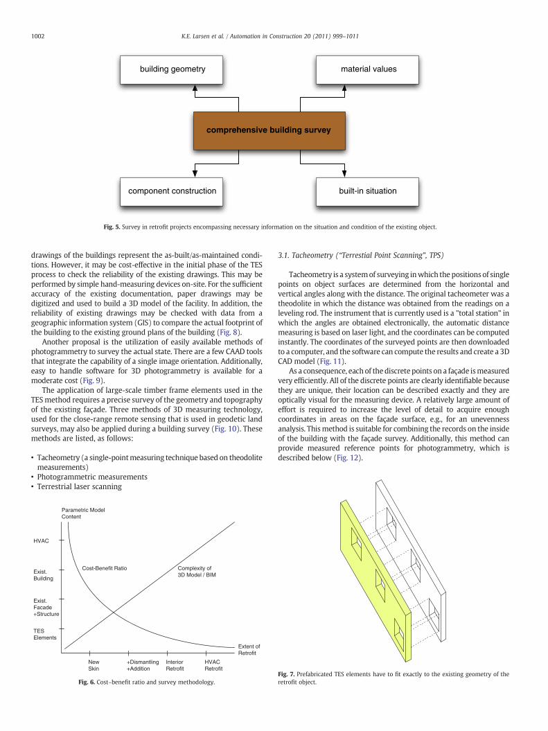
Building Information Modeling (BIM) offers the best solution fordata management and flow throughout a retrofit project from thesurvey to the building site. Currently, there are only a few studies anda small amount of practical experience in this field. However, a recentstudy shows a possible approach for capturing all of the necessaryinformation from a building survey in a uniform building informationmodel as basis for all of the further activities in a project[6] (Fig. 7).
3. Survey in Retrofit Projects: Geometrical and Other Aspects
The existing information about a building can be traced back to itsapproval phase and, in some cases, to its construction phase. Thedocumentation of the actual built situation (“as-built”) and alterationsmade during the operational phase of a building (“as-maintained”) israrely or only partially available. Only in rare cases will the existing
building site of the Buchloe college.
comprehensive building survey
material valuesbuilding geometry
component construction built-in situation
Fig. 5. Survey in retrofit projects encompassing necessary information on the situation and condition of the existing object.
1002 K.E. Larsen et al. / Automation in Construction 20 (2011) 999–1011
drawings of the buildings represent the as-built/as-maintained condi-tions. However, it may be cost-effective in the initial phase of the TESprocess to check the reliability of the existing drawings. This may beperformed by simple hand-measuring devices on-site. For the sufficientaccuracy of the existing documentation, paper drawings may bedigitized and used to build a 3D model of the facility. In addition, thereliability of existing drawings may be checked with data from ageographic information system (GIS) to compare the actual footprint ofthe building to the existing ground plans of the building (Fig. 8).
Another proposal is the utilization of easily available methods ofphotogrammetry to survey the actual state. There are a few CAAD toolsthat integrate the capability of a single image orientation. Additionally,easy to handle software for 3D photogrammetry is available for amoderate cost (Fig. 9).
The application of large-scale timber frame elements used in theTESmethod requires a precise survey of the geometry and topographyof the existing façade. Three methods of 3D measuring technology,used for the close-range remote sensing that is used in geodetic landsurveys, may also be applied during a building survey (Fig. 10). Thesemethods are listed, as follows:
• Tacheometry (a single-pointmeasuring technique based on theodolitemeasurements)
• Photogrammetric measurements• Terrestrial laser scanning
Cost-Benefit Ratio Complexity of3D Model / BIM
Extent ofRetrofit
Parametric ModelContent
HVAC
Exist.Building
Exist.Facade+Structure
TESElements
NewSkin
+Dismantling+Addition
InteriorRetrofit
HVACRetrofit
Fig. 6. Cost–benefit ratio and survey methodology.
3.1. Tacheometry (“Terrestial Point Scanning”, TPS)
Tacheometry is a systemof surveying inwhich the positions of singlepoints on object surfaces are determined from the horizontal andvertical angles along with the distance. The original tacheometer was atheodolite in which the distance was obtained from the readings on aleveling rod. The instrument that is currently used is a "total station" inwhich the angles are obtained electronically, the automatic distancemeasuring is based on laser light, and the coordinates can be computedinstantly. The coordinates of the surveyed points are then downloadedto a computer, and the software can compute the results and create a 3DCAD model (Fig. 11).
As a consequence, each of thediscrete points on a façade ismeasuredvery efficiently. All of the discrete points are clearly identifiable becausethey are unique, their location can be described exactly and they areoptically visual for the measuring device. A relatively large amount ofeffort is required to increase the level of detail to acquire enoughcoordinates in areas on the façade surface, e.g., for an unevennessanalysis. Thismethod is suitable for combining the records on the insideof the building with the façade survey. Additionally, this method canprovide measured reference points for photogrammetry, which isdescribed below (Fig. 12).
Fig. 7. Prefabricated TES elements have to fit exactly to the existing geometry of theretrofit object.

Fig. 8. Two images are matched together by identification of discreet points.
1003K.E. Larsen et al. / Automation in Construction 20 (2011) 999–1011
3.2. Photogrammetry
Photogrammetry can be defined as the art, science and technique ofdetermining geometric and other properties of objects by measurementsand observations of the photographs of those objects. The techniques ofphotogrammetry date back to the mid 19th century. For more than acentury, it wasmostly used formapmaking and surveying andwas basedon aerial photography. The use of close-range (terrestrial) photogram-metryhas increasedduring recentdecades, and is aprocess thatwasmade
Fig. 9. Cleaned point cloud of a three-storey
possible by the development of technology, particularly informationtechnology. The introduction of digital cameras in the 1990s dramat-ically changed the possibilities of photogrammetry. Digital cameras anddedicated software for the analysis of photos to create 3D images hasintroduced a new era of digital photogrammetry (Fig. 13).
If photogrammetry is applied to a 3D building survey, then thebuilding is photographed in such a way that every detail (of thesurfaces) is captured in at least two photos. Some basic computingparameters are the information about the interior orientation of the
building with around 10 million points.

Fig. 10. Workflow of a hybrid facade documentation.
1004 K.E. Larsen et al. / Automation in Construction 20 (2011) 999–1011
camera system, e.g., sensor size and pixel resolution, lens type andfocal length. 3D coordinates of discrete points on the building arecomputed based on the coordinates of their imaged points, which aremeasured in two or more photos. For the case in which the object isnearly planar and a high accuracy is not required, the results can also
Fig. 11. Rectified measuring image (left) and wirefram
be obtained from single photo measurements. Single image photo-grammetry is based on the rectification and scaling of images basedon the identification of reference dimensions taken from the realobject. Large and complex objects are recorded from a number ofimages that are stitched together (Fig. 14).
e model with DSM analysis of the facade surface.

M01
M02M06
M07
M10
referencepoint
roof eaves
roof overhang
topographyscan
referencepoint
horizon
terrain niveau
windowedges
floor level(prism/indoor)
device 1position
device 2position
edges
edgeswindowhandmeasure
Fig. 12. Measuring points and reference system for an entire facade model.
1 According to the website for the company ClearEdge 3D, their EdgeWise™software is “the only software capable of automatically extracting truly editable 3DCAD models from ground-based laser-scan” (http://www.clearedge3D.com, accessed18.03.10).
1005K.E. Larsen et al. / Automation in Construction 20 (2011) 999–1011
Photogrammetry is a very robust method because it is not sensitive torough conditions such as shocks or vibrations that occur outdoors or on-site. The amount of data generated guarantees a high level of detail, andthe integrity of the data is ensured. A problemwith façademeasurementsis the large planar areas of walls in which the depth coordinates(Z-dimension) cannot be computed with the required accuracy. There-fore, there is a lackof possibilities for the analysis of the façade topographydue to a small deviation in the range of 1–5 cm, which is typical for mostfaçades. This method is also more difficult to use when combining theinside views and the outside elevation of a building.
3.3. Laser Scanning (“Terrestrial Laser Scanning”, TLS)
3D laser scanning describes the three-dimensional measurement ofthe surface of an object by the analysis of the reflected light from a laserbeam that is scanned over the surface of the object. The acquisition ofsingle measurements is comparable to tacheometry because the polarcoordinates are derived from the angular and spatial deviations of thelaser beam[7].
There are various measurement principles for laser scanners. Laserscanners that are relevant for buildings use the “time-of-flight” principle(TOF). The distance is measured bymeasuring the difference in the timefrom emitting to the detection of the return of a laser pulse.Mirrors and/or rotating heads are used to control the horizontal and vertical angles ofthe laser light. A TLS can collect a large number of points (called “point
clouds”) in a short time, from a few thousand to several hundreds ofthousands of points per second with a resolution of point spacing ofapproximately 1 mm. Theproblemwith the TLS point clouds is that it is alabor-intensive process if significant corner points must be extracted.This presents amajor challengewhen analyzing the data in point cloudsand converting them into useful information regarding the size andshape of objects, e.g., in a 3D CAD model.
Methods for the automatic creation of a 3D CAD model from apoint cloud are currently under development; however, there are onlya few products currently on the market.1 The post-processing of 3Dimaging data and the generation of 2D drawings and 3D models fromthese data are time-intensive tasks and require specialized experi-ence. This technology allows for the documentation of scanned areasalong with pictures, which are acquired with combined/integratedcameras, and provides better spatial impressions and more realistictextures.
In addition to the façade survey, this method has a high capabilityto measure the speed and level of detail for interior integration andthe analysis of surfaces. Currently, some major issues are the cost ofthe application and the time factor for post-processing the 3Dmodels.

Survey on-site
3D Model(Optional BIM)
3D TES EnergyFacade Reverse Engineering
3D LaserscanningRaw data of scan+ Reference Grid+ Quality Assurance
Project ObjectivesPurpose
Clean point cloud+ Orientation+ Georeferencing+ Topography+ Topology
Simplified Facade+ Function+ Structural Simulation+ Energy Demand+ Daylight Simulation+ Retrofitting Process+ 4D / 5D Planning
Element geometry+ Integration Parts+ Calculations+ Thermal Resistance+ Life Cycle Assessment
durin
g assembly Instrument
Filter
VisualisationFilter
Fig. 13. Generation of a 3D model from 3D image data.
1006 K.E. Larsen et al. / Automation in Construction 20 (2011) 999–1011
3.4. 3D Laser Scanning for TES Projects: Possibilities and Challenges
For several years, the aerospace, automobile and petroleumindustries have benefitted from using 3D laser scanning for the captureof the existing conditions of structures and objects. Although thebuilding industry has gradually started to realize the benefits of thistechnology, actual experiences are not well organized. One exception isthe General Services Administration (GSA), which is an agency of theUnited States government. Since 2006, The GSA Office of Design andConstruction has maintained a program to introduce laser scanning forthe as-built/as-maintained conditions of federal buildings with the goalof incorporating the geometric information in Building InformationModels. The pilot studies include historic buildings and a modern30-story building.
The laser-scanning program is a part of GSA's National 3D–4D-BIMProgram, which was established in 2003. The program has produced aseries of reports regarding their work, which can be obtained from theGSA website at http://www.gsa.gov/bim[8]. Because the GSA is one ofthe few professional building owners and managers that hassystematically used and studied the use of 3D laser scanning for facility
management, it is advantageous to perform a more detailed review oftheir results. The GSA BIM Guide for 3D Imaging is currently the de factohandbook and the only guide that exists for professionals, such asbuilding owners and architects/planners, who need to specify a desiredoutcome for 3D imaging projects[9].
A relationship of the economic restrictions with the rising precisionof certain surveying methods was observed by Scherer[10]. Theeconomical and technical decision to use laser-scanning systems versusother methods depends on several factors. The GSA concluded that, forjobs involving simple geometries and readily-accessible work sites, 3Dmeasuring systemsmight not be the best choice. However, if a high levelof detail is required for complex geometries, the technology might be aviable alternative. A traditional field of application is historic buildingsthat often contain a large amount of complex ornamentation. Theviability is determined by construction unevenness analysis inwhich 3Dlaser scanning is currently the most powerful solution. According to theexperiences of the GSA, other technologies (e.g., photogrammetry) andtraditional surveying methods may offer better or more cost-effectivealternatives, depending on the scope of work and the anticipateddeliverables. Thus, an importantfirst step in the TES process is to identify

Fig. 14. The volumetric model of the imported wireframe geometry of the existing building in SEMA.
1007K.E. Larsen et al. / Automation in Construction 20 (2011) 999–1011
the contexts and projects in which the benefits of 3D imaging can beexploited.
The software developer Cadwork has addressed the challenges indevelopingsoftware solutions that link thesurvey results to theplanningand fabrication software.2 The software tool is prepared for a directconnection with a total station, which controls the survey and collectsthe data. There is also the possibility of operating with reduced pointclouds from 3D laser scanning. However, there is still post processing tobe performed after surveying to generate a sophisticated 3D model.Tools such as this, with direct connections to surveying instruments,provide a strong and seamlessworkflow formanufacturers / contractors.However, they are not used in design work because they are CAD/CAMexpert systems.
3.5. 3D Geometric Survey: Some General Considerations
According to El-Hakim and Beraldin [11], the key performancecriteria that should be considered with respect to the applicationrequirements and constraints are as follows:
• Geometric fidelity of the final model (the accuracy or uncertainty)• Generated level of detail (spatial resolution)• Model completeness (percentage of object or site captured)• Impact of the environment (surface type, accessibility, robustness,etc.)
For the TES process, there are a few other aspects of relevance, asfollows:
• Integration of the interior (preparation of thewindowsill and reveals)• Topography analysis methods (digital surface model, DSM applica-ble to data)
Inmost TES projects, it is likely that a combination of the three above-mentioned approaches (3.1–3.3) is necessary to develop accurate, cost-effective, timely and comprehensive as-built/as-maintained informationin the form of a 3Dmodel. The techniques ofmodern surveyingmethods
2 Personal information from Mr. C. Levers, from cadwork informatik SoftwareGmbH, Hildesheim, providing the identically named 3D CAD / CAM tool. (http://www.cadwork.com).
can also be applied by construction professionals. However, as a generalrule, the services of professionals within the field of 3D surveyingwill berequired for the use of any of these 3D measuring technologies.
To achieve a 3D model that is usable in construction, the singlecoordinates must at least be connected by lines. The final result thenconsistsof a simple3Dwireframemodel.Moreadvancedmethodsdeliversurface (b-rep) or even volumetric models. The data must be processedmanually or automatically to recognize the borders (wireframe), definethe included areas (b-rep) and combine the related areas (volumetric).Attributes for object classification can be assigned as amodel finalization,whichmaybeuseful for further analysis / computing in life cycle analysis,structural analysis, Building Information Modeling, etc.
3.6. Accuracy/Tolerances in the Geometrical Survey
In addition to specifying the deliverables from the surveyor as towhat should be scanned and modeled, a survey solicitation should alsoinclude a specification of the tolerances and minimum artifact size (theresolution of the scan). The minimum artifact size is the dimension ofthe smallest recognizable feature. Smaller tolerances and higherresolutions increase the scan times; thus, they also increase the cost.
To describe the relationship between the measures of the modeland the true values, various authors use concepts such as “accuracy”or “tolerance”. For instance, the CCEM Retrofit Project proposed thatthe required accuracy (1 σ) should be around ±4 mm in the windowareas and ±7 mm in the roof/façade area.[12]
It is necessary for an economic survey to distinguish between thediscrete points and the random points on surface areas. Discrete points(e.g., window edges or corners) require a high accuracy of spatialdistances (x, y, z) in the rangeof±7–10 mm.3 The randompoints for theanalysis of the topography have a rasterized grid between 10 and 50 cmover the façade surface and a highaccuracy of±5–8 mmindepth.Usinga combination of the different methods (e.g., TLS and TPS), it is possibleto quickly obtain reliable results and additional precision[13]. The abovementioned values are the resolutions (level of detail) and tolerancesthat we propose for retrofit projects based on the TES method.
3 Personal information from the industry partners of the TES EnergyFacade project.

1008 K.E. Larsen et al. / Automation in Construction 20 (2011) 999–1011
3.7. Survey of Irregularities in the Building Façade
The documentation of the topography of the existing façade isnecessary for successful application of the TES system. Only in rarecases are buildings regular and precise in every way. Irregularitiesconsist of sloping walls (out of plumb) and an unevenness of thefaçade, which should be documented in the digital surface model.
A standard TES energy façade element is rectangular and rigid.Consequently, a smoothing layer between the element and the existingwall should be considered to adjust the unevenness of the originalsurface. The dimensions of this layer must be carefully evaluated byconsidering the structural issues, building physics, issues related to themounting of the elements and additional economic issues.
The computation of a digital surface model (DSM) and a deliverableas a contour line model (CLM) is a method that was tested in the TESproject[13]. A DSM typically provides a digital representation of thetopography of the ground level with data such as vegetation andbuildings, etc.Within the framework of the TES-project it is applied to ahigh-resolution 3D image of a vertical façade. The basis of thismodel is atriangulated irregular network or a rectangular grid calculated byapproximation. A CLM consists of the resulting set of contour linesoriginating from virtual horizontal sections through a DSM. The rawdata for the3D image canbeacquiredwith eachof the three close-range,remote-sensing methods. However, 3D laser scanning is the onlyautomated method that provides a sufficient amount of randomlymeasured single points of the façade areas to compute a detailed DSM.The rasterized grid has a recommended resolution of 10–50 cm. Themeasured façade surface points will be computed with an appropriatestepping height of 5 mm for the contour lines.
Each façade elevation has its own DSM that contains only a subsetof the surface points. The elevation is based on a defined localcoordinate system with a horizon and a basic reference point for thiselevation. The defined horizon leads to the horizontal direction (Xdimension); additionally, there is the corresponding vertical direction(Y dimension) and the depth is represented by the third orthogonaldirection (Z dimension).
3.8. Survey of a Building's Surroundings
The surroundings of an existing building, including the neighboringbuildings and vegetation, lot borders, etc., must be considered in theplanning phase. Two examples that will illustrate the need for aholistic approach are listed, as follows:
1. For an analysis of the natural lighting conditions of a building, theposition and size of the surroundingbuildings and large trees, etc. areneeded.
2. The site logistics handle the transportation of the elements to thebuilding site and their handling on-site. Any possible hindrancesshould be documented. Modern surveying methods, especially 3Dlaser scanning, allow for a quick and thorough documentation of thesurroundings. The level of detail of information for this overview canbe reduced compared to the level of detail that is required for thebuilding itself.
3.9. Solicitation and Objectives for the TES Process 3D Survey
The experience acquired by theGSA in soliciting 3D imaging projectsusing laser scanning is also applicable to the solicitation of surveys ingeneral, independent of the type of survey technology. According to theGSA, the detailed specification of each aspect of the desired outcome isthe key to success [9, p.2].
First, the project team should clearly state the objectives for the 3Dimaging project. It should identify the areas, surfaces, and objects whichneed to be imaged. A good understanding of the objectives is essential inhelping the contractor design a scan plan (e.g., instrument locations,
required resolutions) that maximizes the product deliverable whileminimizing costs.
Typical critical points in the 3D geometrical survey in the TESprocess are given in the following list:
1) The height and width of the façades (outer edges and corners).2) The geometry of the eaves and roof overhang.3) The exact location and dimensions of existing window openings.4) The exact level of structural parts that will serve as the basis for the
fixation of the elements to the wall, e.g., concrete floor slabs inbuildings with non-load-bearing external walls.
5) Issues such as the unevenness of the façade surface (includingbumps or holes of a critical size), curvature, and slopingwalls (out-of plumb conditions).
6) The height of the terrain.7) The reference height and horizontal level marked in themodel and
in reality.8) Fixed reference points on each façade surface repeated in the
model for the adjustment of the TES during assembly.9) Local coordinate systems for each façade plane.
Finally, the results of the survey should consider the requirementsof the entire design, engineering and production team. The possibil-ities for the final 3D images and 3D models are as follows:
1) A fully registered and cleaned high-density (HD) point cloudof the façade as a result of 3D laser scanning (ready for reverseengineering). An addition of the interior is possible. The3D image is arepresentation (i.e., a mould) of the existing façade. The openingsand assemblies are remodeled by geometric or parametric repre-sentatives, which are adjusted to the point cloud.
2) A 3D wireframe model of the façade derived from one of themeasurement methods described above. This is an interpretationand idealization of the 3D survey data. Further information on thefaçade topography is required.
3) A 3D surface model — an enhanced version of the wireframe modelwith a triangulated façade surface. This could be similar to the actualsolution if the resolution of the meshed surface is high enough.
4) A 3D volumetric model also parameterized with interior surfacesbased on a point cloud (a highly sophisticated post-processingand modeling process is required, and the model will remain as asimplified interpretation of the existing object). Additional infor-mation such as the façade topography is required.
Recently, multi image photogrammetry software tools havebecome available and can compute dense point clouds from images.(Zscan and Photomodeler Scanner). [14] The performance of these toolsshould be proven for application in the TES process. The low depthresolution may be a hindrance for photogrammetry and the problemof the integration of interiors.
4. Digital Workflow
The TES process can be considered as a frictionless informationflow of digital data from the documentation process to design andengineering, further on to element prefabrication and site assembly;the digital data collected by the TES process can be used in the futurefor facility management. Throughout the process, the same data arereused and enriched by the various participants. This “digital chain” isa continuous digital and seamless organization process from survey,planning and production design to construction [15].
4.1. Building Information Modeling (BIM)
Object-orientedCADsystemshave replaced2Dsymbolswithbuildingobjects that are capable of representing the behavior of commonbuilding

Table 1Comparison of the three surveying methods.
Tacheometry Photogrammetry 3D Iaser scanning
1009K.E. Larsen et al. / Automation in Construction 20 (2011) 999–1011
elements. These building elements can be displayed in multiple viewsand can have non-graphic attributes assigned to them. The inclusion ofparametric 3D geometry (with variable dimensions and assigned rules)adds “intelligence” to these objects and allows for the representation ofcomplex geometric and functional relationships between the buildingelements.
Capturing these relationships and behaviors was not possible inthe earlier CAD paradigm. In a Building Information Model (BIM),each of the intelligent building objects that compose a building designcan coexist in a single project database (or “virtual building”) thatcaptures everything that is known about the building. A BuildingInformation Model should provide a single, logical, consistent sourcefor all of the information associated with the building.
Because a BIM relies on machine-readable representations, the datafromthevirtualmodels canbeused inmanydifferentways. Among thesebenefits are: collision control, consistencies within drawings, automaticgeneration of bills of material, energy analysis and cost estimation[16].Both practical experience from real-life projects and academic studiescurrently confirm the benefits of a BIM to create built structures moresustainably, more efficiently and more cost-effectively[17].
A major challenge for the TES process in relation to a BIM is thatcurrent BIM software does not handle detailed architectural workrelated to existing buildings, such as walls out of plumb and otherirregularities. Furthermore, the creation of components in some BIMsoftware packagesmay be a time-consuming and costly task. Finally, thesoftwaredoesnot support theparadigmof reverse engineering, anddoesnot handle complex survey data or provide any functional analysis.
As a result of the experiences of the TES project, a step-wise use of aBIM for the TES is being proposed. If a new and geometrically identicalskin is applied to an existing building, then only the new elements andthe existing façade surface with openings should utilize the BIMintelligence. The larger the extent of the retrofit, the more complex themodelwill become, and thebenefit-cost-ratiowill decrease for theentireproject.
Another solution that may soon be applicable is the integratedcapability of the handling of large point-cloud data in CAD and BIMsoftware. The construction software industry has recognized a growingapplication for this type of geometric data. Themovement of specializedtools into a broadermarketmakes theworld of reverse engineering (RE)available for the construction industry. This is an overdue development,as the retrofit market in the EU has increased continuously during thelast two decades and established the demand for such tools. Thefields ofmechanical engineering and dental restoration already profit from theuse of RE for the fabrication of individual components that must fitprecisely into random gaps or on irregular surfaces, e.g., occlusalsurfaces. A point cloud that is accessible by construction softwarefacilitates an adaptation of a planar TES layer onto an uneven 3D imageof the façade. Fittingwindows correctly into their position in the virtualmodel andnarrowing the physical gap betweenold substances and newelements arebasic operations in theCADsystems. Theprimary result is alean process that causes post processing to be redundant. Furtheradvantages of this method are listed, as follows:
• A surveyor only provides a registered, cleaned and geo-referencedpoint cloud
• The filtering and interpretation of data is obsolete• A high-definition point cloud is used as a “mould”• A fast and interactive element adaption• Operation and control by a construction expert
Geometric fidelity ++ + ++Level of detail o ++ +Model completeness o + ++Interference oa + oa
Interior integration ++ + ++Added VaIue (analysis) + o ++
a Devaluation because of sensitivity due to vibrations and problems with invisible,shaded points.
4.2. BIM and TES
If a geometrical digital model only contains the 3D data and no objectattributes, this model cannot be defined as a “Building InformationModel”. Thesemodels canonlybeused forgraphicvisualizationsandhave
no intelligence at the object level. They are appropriate for visualizationbut provide no support for data integration and design analysis[18].
Currently, only a small amount of documented evidence existsregarding the use of a BIM in building renovation. However, one studyperformed by Finnish researchers shows interesting possibilities forparametric 3D modeling in building renovation in which an eight-floor office building in Helsinki was used[5].
For the TES process, the surveyor provides a digital 3D model(without any object attributes) to the designer, using a file format suchas DWG or an open document format such as STL[19]. The model canthen only be used as a 3D model throughout the entire process becausethe fabricator and the contractor who will mount the elements do notneed any information regarding the object attributes. However, if thedesigner decides to use a BIM, this may facilitate other steps in theprocess, such as energy simulations. However, only the façades willcontain objects with attributes; the rest of the building will not.
The fabricator only requires the geometrical data from the designerfor the production of the elements and can import the data from thedesigner's 3DCADmodel into theCAD/CAMsoftware in a convenientfileformat, e.g., STL or IFC. Previous experience shows that fabricators in theEuropean timber building industry are reluctant to import a 3D modeland use this directly for the creation of the production codes in theirCAD/CAM software. Most fabricators prefer to build the model fromscratch using their own software to ensure that the model is consistentwith their fabrication requirements. Similar experiences have also beenreported for the US precast concrete manufacturing industry[20]. In astudy of the BIM data exchange of precast concrete fabrications, Jeong etal. [21] observed that when contract drawings are completed and beforea fabricator is selected, the building components rarely incorporate anyfabrication process considerations during the architectural design stage.As a result, the fabricators must duplicate work because they mustregenerate the detailed documentation that is required for thefabrication and erection of the building.
The above-mentioned experiences demonstrate that an integratedcollaboration between the designer, fabricator and contractorthroughout the design process is of vital importance to streamlineprojects and make them more cost-efficient.
4.3. Data Processing and Digital Workflow: A Case Study
In a retrofit project for ABG Frankfurt Holding in Rotlintstraße,Frankfurt, which was funded by the Hessisches Ministerum fürWirtschaft, the objective was to examine the current methods andtools to guarantee a frictionless digital chain. The first step was a surveybased on the so-called hybrid methodology by combination of results oflasermeasuring technologieswithphotogrammetry, of Prof.Wunderlichfrom the Department of Geodesy, TUM [23]. The acquisition of the raw3D imaging data was accomplished using tacheometry, 3D laserscanning and 3D photogrammetry. The hybrid methodology allowstests of the fidelity of the measuring results and enhances the overallprecision of the 3D model by combination of results. Furthermore, ituncovers the weak point of photogrammetry due to their impreciseresults of depth values of comparatively plane façade surfaces.

1010 K.E. Larsen et al. / Automation in Construction 20 (2011) 999–1011
The application of the threemethodswas for a comparison test of theusability and accuracy of the different methods. The final data of thesurfacemodel and the input for theDSMwereprovidedbya3D laser scan(Leica Scanstation 2). The original scan resolution was a sample rate of1 cm from a distance of 20 m. The density of the point cloud for the DSMwas reduced to around 1.5% of the amount of points (Table 1).
A 3D wireframe model of the façade geometry with the cut offwindow openings was processed with surveying expert systems (RolleiMetric®, Cloudworx®). The 3D façade model was finalized with AutoCadArchitecture® and provided as a DWG file along with georeferenced,oriented and rectified TIFF images. The images provided amore detailedelevationof the façadeanda full geometric documentationof the existingfaçade.
In an additional step, the model of the renovation object wasexported to the timber construction software tool SemaExperience®. Theimport of the 3D wireframe model into the parametric CAD/CAMsoftware occurred without the loss of any data. Finally, the wireframemodelwas translated into a volumetric / parametricmodelwithwindowopenings and wall attributes. This model serves as a limitation or areference object to which the new TES elements are adapted.
5. Conclusion
Considering the importance of energy performance retrofits ofexisting buildings in the agenda of regional and national policies andthe size of this market, it is obvious that retrofit projects, in the yearsto come, will be a major challenge for the building industry.
Additionally, the prefabrication approachhasmultiple advantages asa sustainable building solution. Thegeneral advantages of prefabricationare also applicable to the TES method. These advantages include thefollowing [22]:
• A high quality due to the construction work of the elements beingperformed in the controlled environment of a factory.
• Less waste because less adaption and adjustment is necessary.• The waste generated in the prefabrication plant can be recycled.• Lower erection costs on-site.• Minimized construction work on-site.• No construction moisture during the erection process.
Although the actual fabrication of the elements and assembly on-siteis efficient andquick, some challenges remainduring thedocumentationand planning stages of the TES process to streamline the method andmake it more cost-effective. As discussed in this paper, these challengesare listed, as follows: (1) the efficient and automated documentation ofthe as-built/as-maintained condition of the existing buildings; (2) theextendeduse of BIM technologies during theplanning stage, the creationof a continuous digital chain from the initial documentation to the on-site phase and subsequentmanagementof the retrofitted building. Thus,the requirements for further development are related to automation inthe post processing of data from 3D laser scanning and innovativedevelopments in the use of BIM tools for the renovation and retrofittingof existing buildings.
High-precision remote sensing provides cost-efficient methods forsurveying the building stock. The acquired data is of a good qualityand can be used in prefabrication. Consequently, the level of detail andthe significant coordinates must be identified both by the surveyorand the customer. The general lack of 3D planning methods and BIMin architectural offices, especially in retrofitting projects, has hindereda continuous digital workflow.
To obtain an adequate cost–benefit ratio, consulting from a surveyoris necessary. Cost control can also be accomplished by the stepwise useof appropriate surveying methods. Digital technology allows for thisapproach and guarantees consistency. There is also hybrid surveyhardware on the market, the so-called intelligent total station, whichintegrates the previously described measurement methods into onesolution. A user-required specification is required to define the content,
the level of detail and a description of the 3Dmodel. The increasing useof 3D methods in the planning stage is a precondition for retrofittingprojects to reduce costs and avoid errors. Furthermore, the use of theBIM tools in retrofit projects requires a deeper examination, and theircapabilities should be enhanced on the survey side.
There are large requirements in terms of the tolerances and contentto prepare useful surveying results for a TES EnergyFaçade retrofit.As a consequence, post processing the survey data into an abstract3D wireframe is a costly and responsible task. The surveyor has alarge amount of responsibility for this task and requires additionalknowledge in construction and close cooperation with the client.
In summary, the conclusions demonstrate that modern surveyingmethods combined with reverse engineering methods are necessaryfor retrofit projects. They can optimize the workflow, enhance therobustness of the TES method and facilitate the application of prefabri-cation to retrofit projects.
Acknowledgements
Wewould like to thank Prof. T. A. Wunderlich and Thomas Schäferfrom the Chair of Geodesy at TUM and Klaudius Henke from the Chairof Timber Structures and Building Construction at TUM. We also wishto acknowledge the cooperation and research contributions of the TESpartners in Finland and Norway.
References
[1] Energy Efficiency in the North Amercian Existing Building Stock. IEA informationPaper. OECD/IEA. Paris. 2009 Directive 2002/91/EC of the European Parliamentand of the Council of 16 December 2002 on the energy performance of buildings.Available from: http://eur-lex.europa.eu/smartapi/cgi/sga_doc?smartapi!celexplus!prod!DocNumber&lg=en&type_doc=Directive&an_doc=2002&nu_doc=91.Accessed November 06, 2009.
[2] TES Energy Façade: Timber based element system for improving energy efficiencyof thebuildingenvelope (www.tesenergyfacade.com) is aprojectunder theumbrellaof the European Research platform WoodWisdom-Net (www.woodwisdom.net).The TES Energy Façade project has academic and industry partners from Finland,Germany and Norway.
[3] R.J. Abella, J.M. Daschbach, R.J. McNichols, Reverse engineering industrialapplications, Computers and Industrial Engineering 26 (1994) 381–385.
[4] Spar Point Research LLC, Capturing Existing Conditions with Terrestrial LaserScanning (2006). Available from: http://www.sparllc.com/cec.php. AccessedAugust 24, 2009.
[5] M.Rajala,H. Penttilä, Testing3Dbuildingmodelling framework inbuilding renovation,in: V. Bourdakis, D. Charitos (Eds.), Communicating space(s), Proceedings of the 24thConference on Education and Research in Computer Aided Architectural Design inEurope, Volos, 6–9 September, 2006, pp. 268–275.
[6] R. Göttig, J. Braunes, Building Survey in combination with building informationmodelling for the architecural planning process, in: G. Çağdaş, B. Çolakoğlu (Eds.),Computation - the new realm of architectural design, Proceedings of the 27thConference on Education and Research in Computer Aided Architectural Design inEurope, Istanbul, 16–19 September, 2009, pp. 69–74.
[7] T. Luhmann, Photogrammetrie und Laserscanning Anwendungen für As-Built-Dokumentation und Facility Management, Wichmann Verlag, Heidelberg, 2002.
[8] Published so far under the GSA National 3D-4D BIM Program is:Series 01 - 3D-4D-BIM OverviewSeries 02 - Spatial Program ValidationSeries 03 - 3D Laser ScanningSeries 04 - 4D PhasingSeries 05 - Energy Performance and Operations
[9] The GSA 3D Laser Scanning guide is available from: http://www.gsa.gov/gsa/cm_attachments/GSA_DOCUMENT/GSA_BIM_Guide_Series_03_R2C-a3-l_0Z5RDZ-i34K-pR.pdf. Accessed November 06, 2009.
[10] M. Scherer, Objekterfassung: Was? –Wie? –Wozu?, Eine Analyse mit Schwerpunktbei der Bauaufnahme, Flächenmanagementund Bodenordnung, 4, 2001, pp. 188–199.
[11] S.F. El-Hakim, J.-A. Beraldin, Sensor integration and visualization, in: J. Fryer, H.Mitchell, J. Chandler (Eds.), Applications of 3D Measurement from Images, WhittlesPublishing, Dunbeath, 2007, pp. 259–298.
[12] R. Gottwald, T.Knabl,R.Gottwald, T. Knabl, 3Dmeasuring for building refurbishment,Reporter - The Global Magazine of Leica Geosystems, 59, 2008, pp. 28–31.
[13] S. Rauch, TES EnergyFacade, Fassadendokumentation der Rotlintstraße 116–120,Frankfurt am Main, Technical report Department of Geodesy, Prof. Wunderlich, TUMünchen, 2008.
[14] Information available from: http://www.menci.com/zscan.html; http://www.photomodeler.com/products/pm-scanner.htm. Accessed August 24, 2009.

1011K.E. Larsen et al. / Automation in Construction 20 (2011) 999–1011
[15] P. Dohmen, K. Rüdenauer, P. Dohmen, K. Rüdenauer, Digital chains in modernarchitecture, in: J.B. Kieferle, K. Ehlers (Eds.), Predicting the Future, Proceedings of the25th Conference on Education in Computer Aided Architectural Design in Europe,Frankfurt, 2007, pp. 801–804, 26–29 September.
[16] S. Morad, Building information modeling and architectural practice: on the vergeof a new culture, First International Conference on Critical Digital: What Matters?Harvard University Graduate School of Design, Cambridge, 2008, pp. 85–90, 2008.
[17] J. Mitchell, J. Wong, J. Plume, Design collaboration using IFC. a case study of thermalanalysis, Proceedings of the 12th International Conference on Computer AidedArchitectural Design Futures, Sydney, 2007, pp. 317–329.
[18] C. Eastman, P. Teicholz, R. Sacks, K. Liston, B.I.M. Handbook, A Guide to BuildingInformationModeling for Owners, Managers, Designers, Engineers, and Contractors,John Wiley & Sons, Inc, Hoboken, New Jersey, 2008.
[19] F. Bosche, C.T. Haas, B. Akinci, Automated recognition of 3D CAD objects in site laserscans forproject 3Dstatusvisualizationandperformancecontrol, JournalofComputingin Civil Engineering 23/6 (2009) 311–318.
[20] R. Sacks, I. Kaner, C.M. Eastman, Y. Jeong, The Rosewood experiment — buildinginformation modeling an interoperability for architectural precast facades, Automa-tion in Constrcution 19 (2010) 419–432.
[21] Y.-S. Jeong, C.M. Eastman, R. Sacks, I. Kaner, Benchmark tests for BIM dataexchanges of precast concrete, Automation in Construction 18 (2009) 469–484.
[22] T. Herzog, J. Natterer, R. Schweitzer, M. Volz, W. Winter, Timber ConstructionManual, Birkhäuser, Basel, 2004.
[23] J. Ohlmann-Bartusel, Th. Weber, Th. Schäfer, S. Rauch, 3D-Laserscanning in derIngenieurgeodäsie, in: R. Göttig, G. Schubert (Eds.), forum3D2009 - 3D-Technologienan der Technischen Universität München, Shaker Verlag, Aachen, 2009 (in German).