automation and robotics testbed...
TRANSCRIPT

TESTBED PROGRAMING
Automation and Robotics

SET UP ROBOTC

PLATFORM TYPE
First you select the platform type so that you
can use Natural Language

VEX CORTEX COMMUNICATION MODE
Choose USB only

DOWNLOAD FIRMWARE
The first time we connect to our cortex we need
to make sure they have the updated firmware.
This is a two step process. Step 1

DOWNLOAD FIRMWARE
The first time we connect to our cortex we need
to make sure they have the updated firmware.
This is a two step process. Step 2

OPEN SAMPLE PROGRAM
You need to locate PLTWtemplate – go to open
SAMPLE program.
Immediately Save As “name” to your AR folder

PLTW TEMPLATE
Top comment section for
students to fill their
personal information, as
well as program planning
work.
Section between curly braces is
designated for the actual program.
Beginning and end
of a multi-line
comment
Top
comment
section for
student
information
After
task main ()
is the code.

CONNECT CORTEX
Use orange USB cable to connect your cortex to
the computer.
Turn up the sound and make sure you get “the
bonk” when you plug it in. Make sure it is off
when you connect it.
Then turn cortex on.

CHECK THE WIRING GUIDE
Check your wiring guide to make sure all your
sensors
are in
the right
places.

MOTORS
All our motors are VEX
393 two-wire motors
Two-wire motors can be
plugged directly into
MOTOR ports 1 or 10 on
the Cortex
2-9 need a Motor
Controller wire
126 is full speed – 63 is
half speed

CHECK AND DOUBLE CHECK…
Go to - Robot; Motors and
Sensors Set Up; Standard
Modules; select GTT Testbed

NAMING CONVENTIONS…
The names of your motors and sensors follow
some basic rules
Must be all one word (leftMotor, frontLight, etc.)
Cannot contain any special characters (%, ^, #,
etc.)
Cannot already be a ROBOTC “Reserved Word
(while, motor, task, left, right, etc.)
Check all your motor and sensor names to
make sure they are OK.
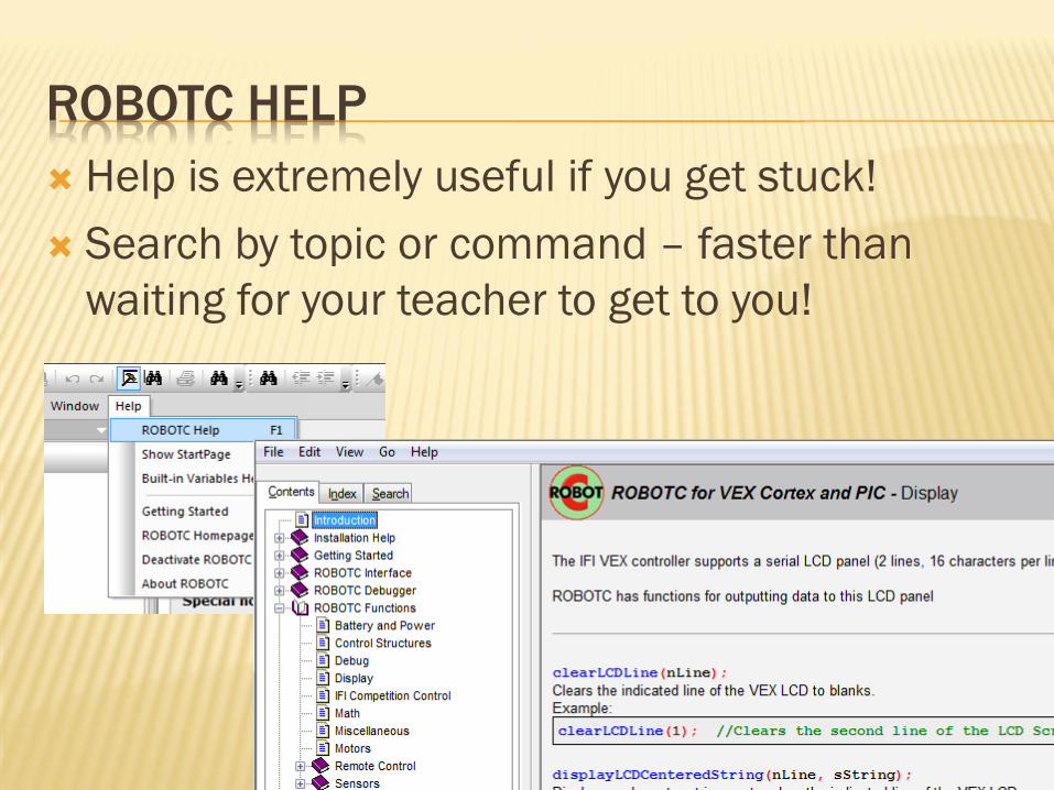
ROBOTC HELP
Help is extremely useful if you get stuck!
Search by topic or command – faster than
waiting for your teacher to get to you!

STOP HERE
AND DO THE
FIRST SET OF STEPS!

BEHAVIOR BASED PROGRAMING
A behavior is anything your robot does: turning on a single motor, moving forward, tracking a, navigating a maze
Three main types of behaviors: basic behaviors – single commands to the robot (turn on a motor)
simple behaviors – simple task performed by the robot (move forward,
track a line)
and complex behaviors – robot performs a complex task (solve the
maze)
Complex behaviors can always be broken down into
simple behaviors, which are then broken down into
basic behaviors
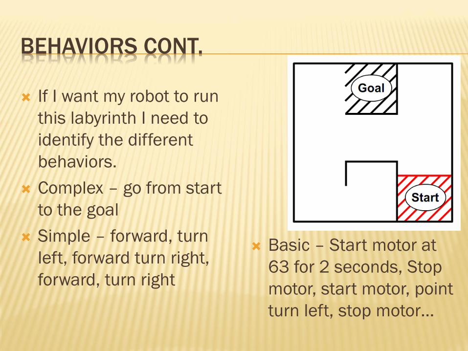
BEHAVIORS CONT.
If I want my robot to run
this labyrinth I need to
identify the different
behaviors.
Complex – go from start
to the goal
Simple – forward, turn
left, forward turn right,
forward, turn right
Basic – Start motor at
63 for 2 seconds, Stop
motor, start motor, point
turn left, stop motor…

PSEUDOCODE
Pseudocode is a regular
language of what you
plan to have the robot
do.
Almost code, but not
quite…
Your lines of Pseudocode
should be listed in the
same order as they will
appear in the Program

NATURAL LANGUAGE
Allows you to drag and
drop code, rather than
typing it all yourself.
Common commands
stored in Function Library
Saves time, and is a lot
easier than remembering
all the rules for writing
code.

MOVEMENT
Commands that allow
you to control individual
motors

SPECIAL
Commands that control
the more unique VEX
Hardware – LED’s

UNTIL
Commands that allow you
to create behaviors where
the robot acts “until” a
certain event
DON’T use Button Press
UNTIL touch-sends a 1
when sensor pressed in
UNTIL bump-sends a 1
when sensor is pressed in
AND released.

WAIT
Commands that wait for an
elapsed amount of time in
seconds or milliseconds
Start motor at speed 63
then put in a wait for 3
seconds to run the motor for
3 seconds

RIGHT MOTOR FOR 5 SECONDS
Starts right motor and
runs it at ½ speed
Motor on for 5
seconds
Stops right motor
Task main() says “I’m
Programing now”
Code between{ and }
Everything goes in order top down.
Drag and drop – customize - run

DOWNLOAD TO ROBOT
Go to Robot; Compile and Download Program
Your code is now on your robot.

STOP HERE
AND DO YOUR FIRST PROGRAM
TEST BED 1
Turn on the right motor and run it for 5 seconds at
half speed (63) then turn it off.

DIRECTION OF MOTORS
You can make motors go in reverse by going to
Robot; Motors and Sensors Set Up; then
selecting reverse for one motor.
Or you can simply type the speed as a negative
number…

STOP HERE
SAVE AS TEST BED 2
Turn on the right motor and run it forward for 5
seconds at ½ speed (63) then turn it off.
Turn on the left motor and run it in reverse at ¾
speed (94.5) for 2.5 seconds then turn it off.
Turn on both motors and run at full power (126), in
the same direction, for 7.25 seconds then turn them
off.

TOUCH SENSORS
Plugged into Digital ports only
Pressed = 1(on) Released = 0(off)
Limit Switches
Bump Switches

SWITCH PROGRAMING
You can add an UntilTouch to make the testbed
wait to start until you press the bump switch.
UntilBump will do this too, but not
UntilButtonPress
You can also add an UntilTouch to make the
testbed run until you press the limit switch

VEX LED
The VEX LED’s all work the same, no matter the
color.
You may name them as you like in the Digital
section of your set up
Make sure they are plugged into the extender
correctly (metal to metal) or you will short them
out
STOP HERE
AND DO
TEST BED 3
Add an UntilTouch for the bump switch to turn on the
right motor forward at ½ speed and the LED on
Then add an UntilTouch for the limit switch to turn off
the motor and LED

POTENTIOMETER
Caution: Excess torque against the internal mechanical stops (can be caused by hand or by a VEX motor) will cause them to wear away. The potentiometer will continue to function, but will have a “dead zone” where the mechanical stops were, where no new values are sent.
Switching the direction the potentiometer is facing will also switch the direction it “counts”. For example: counter-clockwise turns will count 0 to 4095 on one side; on the other counter-clockwise turns will count 4095 – 0.
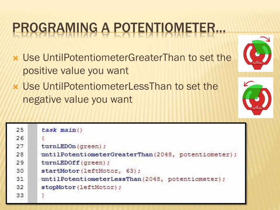
PROGRAMING A POTENTIOMETER…
Use UntilPotentiometerGreaterThan to set the
positive value you want
Use UntilPotentiometerLessThan to set the
negative value you want

STOP HERE
AND DO
TEST BED 4
Turn on the green LED until the potentiometer value is
greater than 2048. Then the green LED should turn off,
and the left Motor should turn on until the
potentiometer is less than 2048.

LINE TRACKING
“Active” Analog Light Sensor
Sends out a IR beam, and measure how much
light is reflected back
Each reads values between 0 and 4095
Usually mounted as a set of 3 ¼ to 1/8 inches
off what it is measuring
You have to calculate a
threshold that allows it to
distinguish light from dark.

THRESHOLDS
A threshold is a value (usually halfway) between
two extremes (light/dark)
Open Sensor Debug Window – make sure that
the refresh rate is set to Once
Place a white surface above the line tracker
and record the value displayed in the window.

THRESHOLDS CONT…

STOP HERE
AND DO
TEST BED 5
Open and close the claw by covering and uncovering
the line follower.
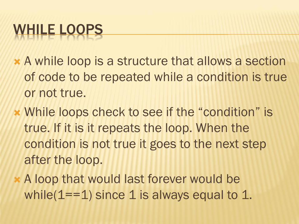
WHILE LOOPS
A while loop is a structure that allows a section
of code to be repeated while a condition is true
or not true.
While loops check to see if the “condition” is
true. If it is it repeats the loop. When the
condition is not true it goes to the next step
after the loop.
A loop that would last forever would be
while(1==1) since 1 is always equal to 1.
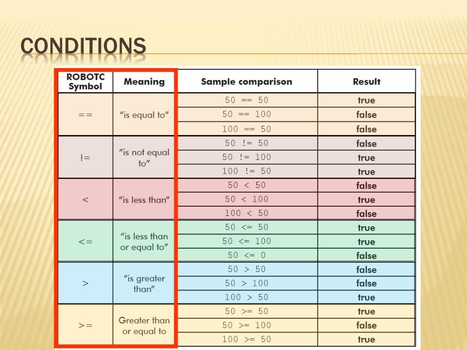
CONDITIONS

PROGRAMING A WHILE LOOP
Put the while loop after the task main() command
Make sure you make an { after the while then a } at
the end
Two opens = two closes

STOP HERE
AND DO
TEST BED 6
Add a continuous while loop (1==1) to
UntilTouch for the bump switch to turn on the right
motor forward at ½ speed and the LED on
Then an UntilTouch for the limit switch to turn off the
motor and LED

IF STATEMENTS – ADVANCED
When the robot reaches an IF statement in the
program, it evaluates the “condition” contained
between the ()
If the “condition is true, any commands
between the braces are run
If the “condition” is false, those same
commands are ignored
Similar to a While loop, but the code does NOT
repeat.

IF-ELSE STATEMENT
This is an expansion of the IF statement.
The IF section still runs the commands inside
the ()
The ELSE allows for specific code to run only
when the condition is false
IF or ELSE is always run…

STOP HERE
AND DO THE
EIGHTH TEST!
Add an IF statement to turn of the LED if the bump
switch is pressed and leave it off if it’s released.
Loop it forever (While…)
Now try converting the IF to an IF-ELSE statement
that runs the right motor if the bump is pressed, Else
the light is on and no motor runs…

MULTIPLE IF-ELSE STATEMENTS
Be careful when using two separate if-else
statements, particularly when they are used to
control the same mechanism.
One branch of each if-else statement is always
run, so you may create a scenario where the
two sets “fight” each other.

MULTIPLE CONT…
In this example, if one
of the touch sensors is
pressed, the rightMotor
will be turned on in one
if-else statement, and
immediately turned off
in the other.

MULTIPLE FIX…
This can be
corrected by
embedding the
second if-else within
the else branch of
the first, so that it
only runs if the first
condition is false.

IF-ELSE SHORTHAND
An embedded if-else can also be represented as an
else if:

STOP HERE
AND DO THE
NINTH TEST!
Use this information to write a multiple If-Else
statement.