automatic weather station maws101 &...
TRANSCRIPT

Automatic Weather StationMAWS101 & MAWS201
USER'S GUIDEM210243en-AJanuary 2002

PUBLISHED BY
Vaisala Oyj Phone (int.): +358 9 8949 1P.O. Box 26 Fax: +358 9 8949 2227FIN-00421 HelsinkiFinland
Visit our Internet pages at http://www.vaisala.com/
© Vaisala 2002
No part of this manual may be reproduced in any form or by any means,electronic or mechanical (including photocopying), nor may its contents becommunicated to a third party without prior written permission of the copyrightholder.
The contents are subject to change without prior notice.

_________________________________________________________________________________
VAISALA_________________________________________________________________________ 1
Table of Contents
CHAPTER 1GENERAL INFORMATION ..........................................................................11
About This Manual..................................................................11Safety .......................................................................................12
General Safety Considerations............................................12Product Related Safety Precautions ...................................12ESD Protection ....................................................................14
Version Information................................................................15Related Manuals .....................................................................15Warranty ..................................................................................16
CHAPTER 2PRODUCT OVERVIEW ................................................................................17
Introduction to MAWS............................................................17MAWS101 Mini AWS...........................................................17MAWS201 Mobile AWS.......................................................18
Product Nomenclature ...........................................................20MAWS Software ......................................................................21
Operating Software..............................................................21Lizard Setup Software .........................................................22MAWS Terminal ..................................................................22
QML102 AWS Logger .............................................................23Memory Expansion Board (Optional) ..................................24
Power Supplies .......................................................................25Internal Battery ....................................................................26Solar Panels ........................................................................26
SOLAR6 with MAWS201................................................26SOLAR6-75 with MAWS101 ..........................................27
Mains Power Supplies .........................................................27A Wall Adapter................................................................27QMP213 .........................................................................27QMP201C.......................................................................28
QBR101 Battery Regulator .......................................29BWT15SX Mains Power Supply................................29
Sensors....................................................................................30Wind Sensor ........................................................................30Air Temperature and Relative Humidity Sensor ..................31Pressure Sensor..................................................................32Precipitation Sensors...........................................................32
QMR101 .........................................................................32QMR102 .........................................................................33
Solar Radiation Sensors......................................................34QMS101 .........................................................................34QMS102 .........................................................................34

User's Guide _______________________________________________________________________
2 ____________________________________________________________________ M210243en-A
QMN101......................................................................... 35Soil Temperature Sensors .................................................. 35
QMT103......................................................................... 35QMT107......................................................................... 36
Soil Moisture Sensor........................................................... 37Water Level Sensors........................................................... 37
QMV101......................................................................... 37QMV102......................................................................... 38
Leaf Wetness Sensor.......................................................... 39Fuel Moisture Sensor.......................................................... 39
Communication Devices ....................................................... 40Communication Modules .................................................... 40
DSU232 ......................................................................... 40DSI485A......................................................................... 41DSI486........................................................................... 41Modem DMX501............................................................ 42
SATELLINE 3AS Radio Modem ......................................... 42Accessories............................................................................ 43
Masts for MAWS101........................................................... 43DKP102.......................................................................... 43DKP12............................................................................ 44
Sensor Arm ......................................................................... 44Carry Case Sets.................................................................. 44
QMM110 ........................................................................ 44QMM120 ........................................................................ 45
CHAPTER 3INSTALLATION ........................................................................................... 47
Preparing Installation ............................................................ 47Unpacking Instructions........................................................ 48
Siting the Station.................................................................... 48Wind.................................................................................... 49Air Temperature and Relative Humidity.............................. 49Precipitation ........................................................................ 50Solar Radiation ................................................................... 50Soil Temperature ................................................................ 50Soil Moisture ....................................................................... 51Water Level......................................................................... 51Fuel Moisture ...................................................................... 52
Installing MAWS Basic Components ................................... 53Installing MAWS101 to a Mast .............................................. 57
On DKP102......................................................................... 57On DKP12........................................................................... 59On Any Wooden Pole or Wall ............................................. 61
Installing MAWS201 to the Tripod........................................ 62Assembling the Tripod ........................................................ 63
Installing Power Supply ........................................................ 64Installing Solar Panel .......................................................... 64Installing a QMP Power Supply .......................................... 69
QMP213 Mains Power Supply....................................... 69QMP201C Solar/Mains Power Supply........................... 70
Installing Sensors .................................................................. 71

_________________________________________________________________________________
VAISALA_________________________________________________________________________ 3
Connecting Cables ..............................................................71Installing Pressure Sensor...................................................72Installing Wind Sensor.........................................................73
Aligning Wind Vane ........................................................73Using winddircal0 Command ....................................73Using Compass and Reference Point .......................74
Installing Air Temperature and Relative HumiditySensor .................................................................................75Installing Rain Gauges ........................................................75
QMR101 .........................................................................75QMR102 .........................................................................76
Installing on the Stand RG35003 ..............................76Installing on a RGB1 Base Plate...............................77Installing on a Pedestal .............................................78Finalizing the Installation...........................................79
Installing Solar Radiation Sensors ......................................81QMS101/QMS102 ..........................................................81QMN101 .........................................................................81
Installing Soil Temperature Sensors ...................................82QMT103..........................................................................82QMT107..........................................................................82
Installing Soil Moisture Sensor ............................................85Installing Water Level Sensors ............................................86
QMV101/QMV102 ..........................................................86Installing Leaf Wetness Sensor ...........................................87
On the Wooden Surface.................................................87To a Pole Mast ...............................................................87To the Sensor Arm .........................................................88Finalizing the Installation ................................................88
Installing Fuel Moisture Sensor ...........................................89Installing Communication Devices .......................................91
Installing Communication Modules......................................91Installing SATELLINE 3AS Radio Modem...........................92
Installing Accessories............................................................94External Memory Expansion Board.....................................94
Installing Software..................................................................96Installing Embedded Software.............................................96Installing MAWS Terminal ...................................................96Installing Lizard....................................................................96
Disassembly of MAWS201 for Transportation ....................97QMT107 Probe Extraction ...................................................97Packing Instructions ............................................................99
CHAPTER 4OPERATION...............................................................................................101
Operation Principle...............................................................101Taking MAWS into Use.........................................................102
Aligning the MAWS201 Station .........................................102Quick Start Instructions .....................................................103
Establishing Terminal Connection .....................................104Using MAWS Terminal Software .........................................105
Selecting the Language.....................................................105MAWS Terminal Main Window..........................................106

User's Guide _______________________________________________________________________
4 ____________________________________________________________________ M210243en-A
Defining MAWS Terminal Settings ................................... 108Preferences Window.................................................... 108Address Book Window................................................. 110
Opening MAWS Service Connection................................ 110Giving Commands ............................................................ 112Closing MAWS Service Connection ................................. 113
Modifying Station Settings.................................................. 113Managing User Levels ......................................................... 115MAWS Configuration File.................................................... 116
Selecting Configuration File.............................................. 116Uploading Configuration File ............................................ 117
Data Logging ........................................................................ 118Log Data Format ............................................................... 120Controlling Logging........................................................... 120Freeing Up Logging Space ............................................... 121Working with Data Log Files ............................................. 121
Selecting Files for Downloading .................................. 122Downloading Files ....................................................... 123Browsing Downloaded Files ........................................ 124Converting Data Log Files to CSV Format .................. 127
Using External Memory Card.............................................. 127Resetting MAWS .................................................................. 128Command Reference for Terminal Connection ................ 129
CHAPTER 5MAINTENANCE ......................................................................................... 133
Routine Maintenance and Calibration ............................... 133Overall Checking.................................................................. 135Sensors and Accessories ................................................... 135
Solar Panel ....................................................................... 135Wind Sensor ..................................................................... 135Air Temperature and Relative Humidity Sensor ............... 138
Humidity Calibration..................................................... 138Changing the HUMICAP®180 Humidity Sensor ......... 139
Pressure Sensor ............................................................... 139Calibration.................................................................... 140
Precipitation Sensors ........................................................ 140QMR101....................................................................... 140QMR102....................................................................... 141
Calibration............................................................... 141Solar Radiation Sensors ................................................... 145
QMS101....................................................................... 145QMS102....................................................................... 146QMN101....................................................................... 146
Soil Temperature Sensors ................................................ 146QMT103....................................................................... 146QMT107....................................................................... 147
Soil Moisture Sensor......................................................... 147Water Level Sensors......................................................... 147
QMV101/QMV102 ....................................................... 147Leaf Wetness Sensor........................................................ 148Fuel Moisture Sensor........................................................ 148

_________________________________________________________________________________
VAISALA_________________________________________________________________________ 5
Cable Maintenance............................................................148Spare Parts............................................................................149
Available Spare Parts ........................................................149Ordering Spare Parts.........................................................149
CHAPTER 6TROUBLESHOOTING................................................................................151
Data Validation......................................................................151The LASTVAL Command..................................................152
Software Operation...............................................................153System Information............................................................155Connection Problems ........................................................156Commands ........................................................................157
Battery Status .......................................................................158Determining MAWS Operation Mode..................................158Power Supply ........................................................................159
Solar Panel ........................................................................159Getting Help ..........................................................................159Return Instructions...............................................................160
CHAPTER 7TECHNICAL DATA.....................................................................................161
Connector Block Descriptions ............................................161Wiring Diagrams ...................................................................163
DSU232 .............................................................................164DSI485A ............................................................................165DSI486...............................................................................166DMX501.............................................................................168
Connectors............................................................................169QMT107.............................................................................169
Battery Charging...................................................................169Power Supply and Battery Types ......................................170
Battery Sensing ............................................................170External Power Supply .................................................170Solar Cell ......................................................................171Lead Batteries ..............................................................171Primary Cells ................................................................172
Lead Battery Charger Operation .......................................172Normal Charging ..........................................................172Quick Charging.............................................................173Float Charging ..............................................................174Temperature Protection................................................174
Specifications .......................................................................175QML102 Logger.................................................................175Accessories .......................................................................176Sensors..............................................................................179
Wind Sensors ...............................................................179Air Temperature and Relative Humidity Sensor...........179Pressure Sensor...........................................................179Precipitation Sensors ...................................................180Solar Radiation Sensors...............................................180

User's Guide _______________________________________________________________________
6 ____________________________________________________________________ M210243en-A
Soil Temperature Sensors ........................................... 182Soil Moisture Sensor.................................................... 183Water Level Sensors ................................................... 184Leaf Wetness Sensor .................................................. 185Fuel Moisture Sensor................................................... 185
Communication Devices ................................................... 186Block Diagrams.................................................................... 187
APPENDIX AGLOSSARY ............................................................................................... 189
List of FiguresFigure 1 Components of MAWS101 Weather Station ......................... 18Figure 2 Components of MAWS201 Weather Station ......................... 19Figure 3 QML102 Logger ..................................................................... 23Figure 4 QML102 Logger without the Cover........................................ 24Figure 5 QMC102 Memory Expansion Board ...................................... 25Figure 6 Compact Flash Memory Card Readers ................................. 25Figure 7 SOLAR6 Solar Panel ............................................................. 26Figure 8 QMP213 Mains Power Supply............................................... 28Figure 9 QMP201C Solar/Mains Power Supply................................... 28Figure 10 QBR101 Battery Regulator .................................................... 29Figure 11 QMW101 Wind Sensor .......................................................... 30Figure 12 QMH101 Temperature and Relative Humidity Sensor .......... 31Figure 13 PMT16A Pressure Sensor ..................................................... 32Figure 14 QMR101 Rain Gauge ............................................................ 32Figure 15 QMR102 Rain Gauge ............................................................ 33Figure 16 QMS101 Pyranometer ........................................................... 34Figure 17 QMS102 Pyranometer ........................................................... 34Figure 18 QMN101 Net Radiation Sensor ............................................. 35Figure 19 QMT103 Soil/Water Temperature Sensor ............................. 35Figure 20 QMT107 Soil Temperature Sensor........................................ 36Figure 21 ML2x Soil Moisture Sensor .................................................... 37Figure 22 QMV101 Water Level Sensor ................................................ 37Figure 23 QMV102 Water Level Sensor ................................................ 38Figure 24 QLW101 Leaf Wetness Sensor ............................................. 39Figure 25 QFM101 Fuel Moisture Sensor.............................................. 40Figure 26 Communication Modules ....................................................... 40Figure 27 SATELLINE 3AS Radio Modem ............................................ 42Figure 28 Installation Mast with Accessories ......................................... 43Figure 29 QMA101 Sensor Arm............................................................. 44Figure 30 QMM110 Carry Case Set....................................................... 45Figure 31 QMM120 Carry Case Set....................................................... 45Figure 32 Siting the Station.................................................................... 49Figure 33 QMV101/QMV102 Sensor in Water....................................... 52Figure 34 Tube Securing Hand Screws ................................................. 53Figure 35 Logger Cover Screw .............................................................. 53Figure 36 Pressure Sensor Tube Connection........................................ 54Figure 37 Battery Connectors ................................................................ 55Figure 38 Aligning Pin and Hand Screws............................................... 55Figure 39 O-rings for Sealing the Tube.................................................. 55Figure 40 Wind Sensor Attachment ....................................................... 56

_________________________________________________________________________________
VAISALA_________________________________________________________________________ 7
Figure 41 Upper Tube Attachment .........................................................56Figure 42 Sensor Arm Support Attachment............................................57Figure 43 Sensor Arm Assembly ............................................................57Figure 44 DKP12 Attachment to a Foundation .......................................58Figure 45 Maws101 Fixed to the Pole with Clamps ...............................59Figure 46 Wind Sensor QMW110 with DKP12 Mast ..............................60Figure 47 Installing the Protective cover Screw......................................60Figure 48 Installation Arm.......................................................................61Figure 49 MAWS101 Fixed to a Wooden Pole with Screws...................61Figure 50 Mechanical Structure of MAWS201........................................62Figure 51 Tripod's Leg Attachment.........................................................63Figure 52 Tripod's Leg Adjustment and Peg Hole ..................................63Figure 53 Tripod's Leg Attachment.........................................................64Figure 54 Solar Panel Fixture .................................................................65Figure 55 Solar Panel Angle Adjustment................................................65Figure 56 Metallic Connector for Solar Panel .........................................66Figure 57 Plastic Connector for Solar Panel...........................................66Figure 58 Wires' Connection to the Terminals........................................66Figure 59 Solar Panel Connector Assembly...........................................67Figure 60 Connector Attached................................................................67Figure 61 Map of Latitudes .....................................................................68Figure 62 QMP213 with Installation Accessories ...................................69Figure 63 Parts of QMP201C..................................................................70Figure 64 PMT16A Location on the Logger............................................73Figure 65 Aligning the Wind Vane ..........................................................74Figure 66 QMH101 Probe and the Radiation Shield ..............................75Figure 67 Mounting Plates Attachment...................................................76Figure 68 Rain Gauge Attachment .........................................................76Figure 69 Rain Gauge Installed On a Stand...........................................77Figure 70 Rain Gauge Attachment .........................................................77Figure 71 Rain Gauge Pedestal Plate Dimensions ................................78Figure 72 Assembling QMR102 on the Ground with Pedestal Plate......79Figure 73 Funnel Fixing Screw ...............................................................79Figure 74 QMR102 Adjustment and the Foam Location ........................80Figure 75 Wiring Diagram of QMR102 ...................................................80Figure 76 Installing QMS101 or QMS102 Pyranometer on
Sensor Arm.............................................................................81Figure 77 Installing QMN101 Net Radiometer........................................82Figure 78 Drilling Procedure ...................................................................83Figure 79 Cleaning the Auger with a Screwdriver ..................................83Figure 80 Soil Temperature Probe Inserted Correctly, Arrow
Pointing to Ground Level Line ................................................84Figure 81 ML2x Soil Moisture Sensor.....................................................85Figure 82 Buried ML2x Sensors .............................................................86Figure 83 Mounting QLW101 to a Wooden Surface...............................87Figure 84 Mounting QLW101 to a Pole ..................................................88Figure 85 QLW101 Installed on Sensor Arm..........................................88Figure 86 Adapter Installed to Connector ...............................................89Figure 87 Installing the Sensor with the Clamp ......................................90Figure 88 Adapter Installed to Connector ...............................................91Figure 89 Module Placement ..................................................................92Figure 90 Radio Modem and the Fixture ................................................93Figure 91 Wire Modifications with Radio Modem ...................................94Figure 92 Communication Modules Removed........................................95Figure 93 External Memory Expansion Board Installed .........................95

User's Guide _______________________________________________________________________
8 ____________________________________________________________________ M210243en-A
Figure 94 Probe Extraction .................................................................... 98Figure 95 QMM110 Carry Case Set....................................................... 99Figure 96 QMM120 Carry Case Set....................................................... 99Figure 97 Aligning MAWS201 on the Northern Hemisphere ............... 102Figure 98 Connecting the Terminal Cable ........................................... 104Figure 99 COM0 Pins for the Terminal Connector............................... 105Figure 100 Select Language Window .................................................... 105Figure 101 MAWS Terminal Main Window ............................................ 106Figure 102 MAWS Terminal Showing Report ........................................ 107Figure 103 Directories Tab in Preferences Window .............................. 108Figure 104 Address Book Window......................................................... 110Figure 105 Address Book Window when Connecting to MAWS ........... 111Figure 106 MAWS Station Settings Window.......................................... 114Figure 107 Selecting an Upload Configuration File ............................... 118Figure 108 Select Log Files for Download Window ............................... 122Figure 109 Set Download Preferences Window .................................... 123Figure 110 Confirming File Deletion after Download ............................. 124Figure 111 Offline Query Window for Browsing Data Log Files ............ 125Figure 112 Select Data Items Window................................................... 125Figure 113 Offline Query Window with Data Items................................ 126Figure 114 Selecting a Binary Log File for CSV Conversion ................. 127Figure 115 QMW101/QMV110 Sensor Assembly ................................. 137Figure 116 QMH101 Probe Maintenance .............................................. 138Figure 117 Static Calibration.................................................................. 142Figure 118 Dynamic Calibration............................................................. 143Figure 119 Dynamic Calibration (Constant Head) ................................. 144Figure 120 Connector Blocks................................................................. 162Figure 121 Basic Wiring Diagram .......................................................... 164Figure 122 DSU232 Wiring Diagram...................................................... 165Figure 123 Suggested T-connection in Dual Port Mode........................ 165Figure 124 DSI485A Wiring Diagram..................................................... 166Figure 125 DSI486 Wiring Diagram for Dual RS-485 ............................ 166Figure 126 DSI486 Default Jumper Locations ....................................... 167Figure 127 DSI486 Wiring Diagram for RS-485 and RS-232 ................ 167Figure 128 DMX501 Wiring Diagram ..................................................... 168Figure 129 Connector of QMT107 (Viewed from Connecting Side) ...... 169Figure 130 Soil Moisture Sensor Dimensions........................................ 183Figure 131 Wiring of QMV101 Water Level Sensor............................... 184Figure 132 QMT107 Soil Temperature Probe Block Diagram ............... 187

_________________________________________________________________________________
VAISALA_________________________________________________________________________ 9
List of TablesTable 1 Manual Revisions ...................................................................15Table 2 Related Manuals.....................................................................15Table 3 MAWS Nomenclature (Basic Set) ..........................................20Table 4 MAWS Nomenclature (Sensor Options).................................20Table 5 MAWS Nomenclature (Communication Options) ...................21Table 6 Installation Accessories ..........................................................21Table 7 MAWS Nomenclature (Optional Accessories)........................21Table 8 Overview of Installation ..........................................................47Table 9 Recommended Tilt Angle for Solar Panel ..............................68Table 10 Default Lower Base Connectors.............................................71Table 11 Default Upper Base Connectors.............................................72Table 12 Cable Pins of ML2x Soil Moisture Sensor ..............................86Table 13 Cable Pins of QLW101 Leaf Wetness Sensor .......................89Table 14 Modified Wiring with QFM101 ................................................91Table 15 Default Configuration for Communication Modules................92Table 16 Quick Start Instructions ........................................................103Table 17 Description of the Toolbar ....................................................107Table 18 Description of Preference Window Tabs ..............................109Table 19 Interpreting Help Texts (the Correct Syntax)........................112Table 20 Description of MAWS Station Settings Window ...................114Table 21 Accessible Commands in Different User Levels ..................116Table 22 Log Memory Capacity...........................................................119Table 23 Log Entry Status ...................................................................120Table 24 LED Blinking Sequences and Card Status Options .............128Table 25 Command Set.......................................................................129Table 26 Greenspan’s Calibration .......................................................139Table 27 Calibration Procedure...........................................................140Table 28 Calibration Factors................................................................145Table 29 Available Spare Parts ...........................................................149Table 30 Some Common Problems and Their Remedies...................155Table 31 Some Common Connecting Problems and Their
Remedies..............................................................................157Table 32 Error Messages ....................................................................157Table 33 Determining Operation Mode by LED Flashing....................159Table 34 Troubleshooting the Solar Panel ..........................................159Table 35 Description of Analog Measurement Channels ....................163Table 36 Description of the Power Channel ........................................163Table 37 The Jumper Settings for Channel B in the RS-485 Mode ....167Table 38 The Jumper Settings for Channel B in the RS-232 Mode ....168Table 39 Cable wire connections ........................................................169Table 40 QML102 Logger Specifications ............................................175Table 41 SOLAR6 Solar Panel Specifications (MAWS201)................176Table 42 SOLAR6-75 Solar Panel Specifications (MAWS101)...........176Table 43 SOLAR12 Solar Panel Specifications (QMP201C) ..............176Table 44 7 Ah Backup Battery Specifications (inside QMP201C).......177Table 45 QBR101 Battery Regulator Specifications
(inside QMP201C) ................................................................177Table 46 BWT15SX Mains Power Supply Unit Specifications
(inside QMP201C) ................................................................178Table 47 QMW101/QMV110 Combined Wind Sensor
Specifications........................................................................179

User's Guide _______________________________________________________________________
10 ___________________________________________________________________ M210243en-A
Table 48 QMH101 Air Temperature and Relative Humidity SensorSpecifications....................................................................... 179
Table 49 PMT16A Pressure Sensor Specifications............................ 179Table 50 QMR101 Rain Gauge Specifications ................................... 180Table 51 QMR102 Rain Gauge Specifications ................................... 180Table 52 QMS101 Global Solar Radiation Sensor Specifications...... 180Table 53 QMS102 Global Solar Radiation Sensor Specifications...... 181Table 54 QMN101 Net Solar Radiation Sensor Specifications .......... 181Table 55 QMT103 Soil/Water Temperature Sensor Specifications.... 182Table 56 QMT107 Soil Temperature Probe Specifications ................ 182Table 57 ML2x Soil Moisture Sensor Specifications........................... 183Table 58 QMV101 Water Level Sensor Specifications....................... 184Table 59 QMV102 Water Level Sensor Specifications....................... 184Table 60 QLW101 Leaf Wetness Sensor Specifications .................... 185Table 61 QFM101 Fuel Moisture Sensor Specifications .................... 185Table 62 SATELLINE 3AS Radio Modem Specifications................... 186
Chapter 1 _________________________________________________________ General Information
VAISALA________________________________________________________________________ 11
CHAPTER 1
GENERAL INFORMATION
About This ManualThis manual provides information for installing, operating andmaintaining MAWS101 and MAWS201 Automatic Weather Stationsequipped with meteorological sensors. This manual consists of thefollowing chapters:
- Chapter 1, General Information, provides important safety, revisionhistory, contact, and warranty information for the product.
- Chapter 2, Product Overview, introduces the MAWS AutomaticWeather Station features, accessories, sensors, and the productnomenclature.
- Chapter 3, Installation, describes how to mechanically put togethera MAWS weather station that is mounted to a portable mast or to apole mast.
- Chapter 4, Operation, provides the instructions for taking MAWSAutomatic Weather Station into use when all the equipment hasbeen assembled and installed.
- Chapter 5, Maintenance, provides information that is needed in thebasic maintenance of MAWS.
- Chapter 6, Troubleshooting, consists of some common MAWSproblems, their probable causes, and remedies.
- Chapter 7, Technical Data, provides the technical data of MAWSand its sensors.
- Appendix A, Glossary
User's Guide _______________________________________________________________________
12 ___________________________________________________________________ M210243en-A
Safety
General Safety ConsiderationsThroughout the manual, important safety considerations arehighlighted as follows:
WARNING Warning alerts you to a serious hazard. If you do not read and followinstructions very carefully at this point, there is a risk of injury oreven death.
CAUTION Caution warns you of a potential hazard. If you do not read andfollow instructions carefully at this point, the product could bedamaged or important data could be lost.
NOTE Note highlights important information on using the product.
Product Related Safety PrecautionsMAWS has been tested for safety and approved as shipped from thefactory. The following safety precautions are not related to anyspecific procedures and therefore do not appear elsewhere in thismanual. They are recommended precautions that personnel mustunderstand and apply during different phases of operation andmaintenance.
WARNING Keep away from live circuits. Operating personnel must observesafety regulations at all times. Component replacement or internaladjustments must be made by qualified maintenance personnel. Donot replace components with the power cable connected. Undercertain conditions, dangerous voltages may exist for some time evenwith the power cable disconnected. To avoid injuries, disconnectpower and discharge circuits before touching them.
Chapter 1 _________________________________________________________ General Information
VAISALA________________________________________________________________________ 13
WARNING Do not service alone. Under no circumstances should any personreach into parts and assemblies that are mains powered and alive, forthe purpose of servicing, except in the presence of someone who iscapable of rendering aid.
WARNING Personnel working with or near high voltages should be familiar withmodern methods of resuscitation.
WARNING Do not service a live system outdoors. Do not open units outdoorswhen the enclosure contains line voltage levels.
WARNING Do not operate in an explosive atmosphere, for example, whenflammable gases or fumes are present. Operation of any electricalinstrument in such an environment constitutes a definite safetyhazard.
WARNING Do not substitute parts or modify the instrument. Because of thedanger of introducing additional hazards, do not install unsuitableparts in the instrument. Contact Vaisala or its authorizedrepresentative for repairs to ensure that safety features aremaintained.
WARNING Be careful when erecting the mast. See that there are no power linesor other obstacles above the mast.
WARNING Secure the mast properly to prevent it from falling. Tighten all theadjustment screws securely.

User's Guide _______________________________________________________________________
14 ___________________________________________________________________ M210243en-A
CAUTION Do not make changes to the wiring. Incorrect wiring can damage thedevice and prevent it from operating correctly.
CAUTION Be careful when moving the mast. To prevent damage to the sensors,remove them (and the sensor arms) before moving the station.
NOTE When disposing of old batteries, be sure to do so in accordance withall regulations applicable in your area.
ESD ProtectionElectrostatic Discharge (ESD) can cause immediate or latent damageto electronic circuits. Vaisala products are adequately protectedagainst ESD for their intended use. However, it is possible to damagethe product by delivering electrostatic discharges when touching,removing, or inserting any objects inside the equipment housing.
To make sure you are not delivering high static voltages yourself:
- Handle ESD sensitive components on a properly grounded andprotected ESD workbench. When this is not possible, groundyourself to the equipment chassis before touching the boards.Ground yourself with a wrist strap and a resistive connection cord.When neither of the above is possible, touch a conductive part ofthe equipment chassis with your other hand before touching theboards.
- Always hold the boards by the edges and avoid touching thecomponent contacts.
Chapter 1 _________________________________________________________ General Information
VAISALA________________________________________________________________________ 15
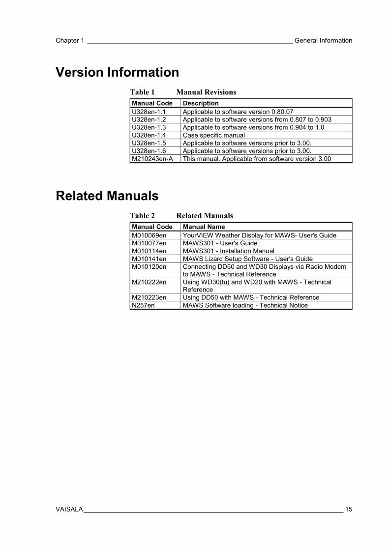
Version InformationTable 1 Manual RevisionsManual Code DescriptionU328en-1.1 Applicable to software version 0.80.07U328en-1.2 Applicable to software versions from 0.807 to 0.903U328en-1.3 Applicable to software versions from 0.904 to 1.0U328en-1.4 Case specific manualU328en-1.5 Applicable to software versions prior to 3.00.U328en-1.6 Applicable to software versions prior to 3.00.M210243en-A This manual. Applicable from software version 3.00
Related ManualsTable 2 Related ManualsManual Code Manual NameM010069en YourVIEW Weather Display for MAWS- User's GuideM010077en MAWS301 - User's GuideM010114en MAWS301 - Installation ManualM010141en MAWS Lizard Setup Software - User's GuideM010120en Connecting DD50 and WD30 Displays via Radio Modem
to MAWS - Technical ReferenceM210222en Using WD30(tu) and WD20 with MAWS - Technical
ReferenceM210223en Using DD50 with MAWS - Technical ReferenceN257en MAWS Software loading - Technical Notice
User's Guide _______________________________________________________________________
16 ___________________________________________________________________ M210243en-A
Warranty
Vaisala hereby represents and warrants all Productsmanufactured by Vaisala and sold hereunder to befree from defects in workmanship or material duringa period of twelve (12) months from the date ofdelivery save for products for which a specialwarranty is given. If any Product proves however tobe defective in workmanship or material within theperiod herein provided Vaisala undertakes to theexclusion of any other remedy to repair or at its ownoption replace the defective Product or part thereoffree of charge and otherwise on the same conditionsas for the original Product or part without extensionto original warranty time. Defective parts replaced inaccordance with this clause shall be placed at thedisposal of Vaisala.
Vaisala also warrants the quality of all repair andservice works performed by its employees toproducts sold by it. In case the repair or serviceworks should appear inadequate or faulty and shouldthis cause malfunction or nonfunction of the productto which the service was performed Vaisala shall atits free option either repair or have repaired orreplace the product in question. The working hoursused by employees of Vaisala for such repair orreplacement shall be free of charge to the client.This service warranty shall be valid for a period ofsix (6) months from the date the service measureswere completed.
This warranty is however subject to followingconditions:
a) A substantiated written claim as to any allegeddefects shall have been received by Vaisalawithin thirty (30) days after the defect or faultbecame known or occurred, and
b) The allegedly defective Product or part shall,should Vaisala so require, be sent to the works ofVaisala or to such other place as Vaisala mayindicate in writing, freight and insurance prepaidand properly packed and labeled, unless Vaisalaagrees to inspect and repair the Product orreplace it on site.
This warranty does not however apply when thedefect has been caused through
a) normal wear and tear or accident;
b) misuse or other unsuitable or unauthorized use ofthe Product or negligence or error in storing,maintaining or in handling the Product or anyequipment thereof;
c) wrong installation or assembly or failure toservice the Product or otherwise follow Vaisala'sservice instructions including any repairs orinstallation or assembly or service made byunauthorized personnel not approved by Vaisalaor replacements with parts not manufactured orsupplied by Vaisala;
d) modifications or changes of the Product as wellas any adding to it without Vaisala's priorauthorization;
e) other factors depending on the Customer or athird party.
Notwithstanding the aforesaid Vaisala's liabilityunder this clause shall not apply to any defectsarising out of materials, designs or instructionsprovided by the Customer.
This warranty is expressly in lieu of and excludes allother conditions, warranties and liabilities, expressor implied, whether under law, statute or otherwise,including without limitation ANY IMPLIEDWARRANTIES OF MERCHANTABILITY OR OFFITNESS FOR A PARTICULAR PURPOSE and allother obligations and liabilities of Vaisala or itsrepresentatives with respect to any defect ordeficiency applicable to or resulting directly orindirectly from the Products supplied hereunder,which obligations and liabilities are herebyexpressly cancelled and waived. Vaisala's liabilityshall under no circumstances exceed the invoiceprice of any Product for which a warranty claim ismade, nor shall Vaisala in any circumstances beliable for lost profits or other consequential losswhether direct or indirect or for special damages.

Chapter 2 ___________________________________________________________Product Overview
VAISALA________________________________________________________________________ 17
CHAPTER 2
PRODUCT OVERVIEW
This chapter introduces the MAWS Automatic Weather Stationfeatures, accessories, sensors, and the product nomenclature.
Introduction to MAWSMAWS is a compact weather station that can be used either with aportable tripod (MAWS201) or with pole masts of different heights infixed installations (MAWS101 and MAWS301). The weather stationcomes with a set of sensors, that measure certain meteorologicalquantities and that have been especially selected for use with MAWS.
MAWS101 Mini AWSMAWS101 can be installed on a pole mast. The logger enclosure isthen attached to a short support arm, which is secured around the mastwith fixing clamps.
The maximum height of MAWS101 is 3 meters. Alternatively, thewind sensors can be installed up to 10 meters away from theelectronics. With an extension cable, this distance can be extendedfurther.

User's Guide _______________________________________________________________________
18 ___________________________________________________________________ M210243en-A
0201-003
Figure 1 Components of MAWS101 Weather Station
The following numbers refer to Figure 1 above.
1 = QMW101 Wind Sensor with a fixing adapter and the 1-metercable
2 = QMR101 Precipitation Sensor3 = QMH101 Temperature and Humidity Probe with radiation
shield4 = QMA101 Sensor Arm5 = QMN101 Net Radiation Sensor6 = Tube, that includes the QML102 logger, QMB101
rechargeable internal battery, and optionally PMT16APressure Sensor
MAWS201 Mobile AWSIf you have purchased a portable MAWS Weather Station(MAWS201) with a basic sensor set, your station will typicallyconsists of the components presented in Figure 2 on page 19.

Chapter 2 ___________________________________________________________Product Overview
VAISALA________________________________________________________________________ 19
1
2 3
4 5
6 7
9809-001
Figure 2 Components of MAWS201 Weather Station
The following numbers refer to Figure 2 above.
1 = QMW101 Wind Sensor with a fixing adapter and 1-metercable
2 = QMS101 Solar Radiation Sensor3 = QMA101 Sensor Arm4 = QMH101 Temperature and Humidity Probe with radiation
shield5 = QMR101 Precipitation Sensor with cable6 = Tube, that includes the QML102 logger, QMB101
rechargeable internal battery, and optionally PMT16APressure Sensor.
7 = Solar panel for generating current for recharging the internalbattery.
In addition to the numbered items, the delivery contains the portablemast assembly consisting of a tripod with adjustable extension legs
User's Guide _______________________________________________________________________
20 ___________________________________________________________________ M210243en-A
attached to the logger housing. The tripod can be easily collapsed tofit in a carrying bag.
NOTE The appearance of the solar panel in your MAWS may differ from theone in the figures.
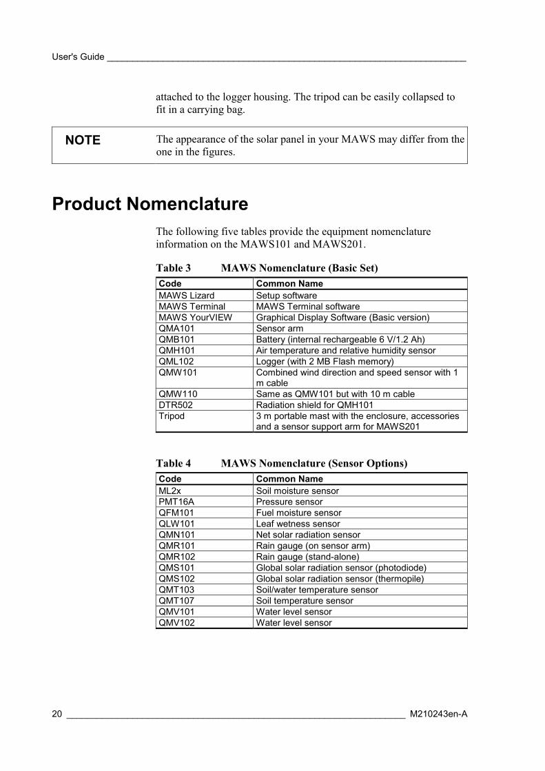
Product NomenclatureThe following five tables provide the equipment nomenclatureinformation on the MAWS101 and MAWS201.
Table 3 MAWS Nomenclature (Basic Set)Code Common NameMAWS Lizard Setup softwareMAWS Terminal MAWS Terminal softwareMAWS YourVIEW Graphical Display Software (Basic version)QMA101 Sensor armQMB101 Battery (internal rechargeable 6 V/1.2 Ah)QMH101 Air temperature and relative humidity sensorQML102 Logger (with 2 MB Flash memory)QMW101 Combined wind direction and speed sensor with 1
m cableQMW110 Same as QMW101 but with 10 m cableDTR502 Radiation shield for QMH101Tripod 3 m portable mast with the enclosure, accessories
and a sensor support arm for MAWS201
Table 4 MAWS Nomenclature (Sensor Options)Code Common NameML2x Soil moisture sensorPMT16A Pressure sensorQFM101 Fuel moisture sensorQLW101 Leaf wetness sensorQMN101 Net solar radiation sensorQMR101 Rain gauge (on sensor arm)QMR102 Rain gauge (stand-alone)QMS101 Global solar radiation sensor (photodiode)QMS102 Global solar radiation sensor (thermopile)QMT103 Soil/water temperature sensorQMT107 Soil temperature sensorQMV101 Water level sensorQMV102 Water level sensor

Chapter 2 ___________________________________________________________Product Overview
VAISALA________________________________________________________________________ 21
Table 5 MAWS Nomenclature (Communication Options)Code Common NameDMX501 Modem module (fixed line)DSI485A RS-485 module (isolated)DSI486 RS-485/RS-232/SDI-12 module (dual-isolated)DSU232 RS-232 module (dual)
SATELLINE 3AS Radio Modem
Table 6 Installation AccessoriesCode Common NameDKP102 2-meter pole mast for MAWS101DKP12 10-meter pole mast for MAWS110QMA101 Sensor support arm
Table 7 MAWS Nomenclature (Optional Accessories)Code Common NameMAWS YourVIEWwith TCP/IP
Graphical Display Software with TCP/IP connection
QBR101 Battery regulatorQMC102 Memory Expansion BoardQMM110 Carry case (canvas bag for tripod, hard case for
sensors)QMM120 Carry case (hard case for tripod, hard case for
sensorsQMP201C Solar/Mains Power SupplyQMP213 Mains Power SupplySOLAR6 6 W solar panel for MAWS201SOLAR6-75 6 W solar panel with 6 m cable for MAWS101
MAWS Software
Operating SoftwareThe embedded operating software runs in the QML102 AWS logger.Access to the operating software commands can be gained using theMAWS Terminal.

User's Guide _______________________________________________________________________
22 ___________________________________________________________________ M210243en-A
Lizard Setup SoftwareLizard Setup Software is used to modify the software parameters andoperation of the MAWS weather station. With the Lizard software youcan create or modify a setup file that informs MAWS how to operate.
Creating a setup with Lizard Setup Software consists of three stages.First, you define an assembly for the MAWS weather station. Thenyou define the necessary measurements and the calculations derivedfrom them. Finally, you define reports and log groups from themeasurement results.
The setup file on your PC is finally generated, in other words,converted into a format that MAWS understands, and then transferredinto MAWS and taken into use.
MAWS TerminalMAWS Terminal is the terminal software for working with MAWSAutomatic Weather Stations. MAWS stations measure weather dataand store it in log files. With the MAWS terminal software, you candownload these files to your PC and view them.
When you start using MAWS, the first thing you need to do is todefine what weather parameters you want to measure and at whatfrequency. You can do this by uploading a configuration file fromyour PC to the MAWS.
MAWS Terminal is also used for setting the station specificparameters such as the station name, altitude, pressure sensor height,and sensor specific calibration coefficients. In addition, the date andtime can be set using the easy-to-use MAWS Station Settingstemplate.
After you have uploaded the configuration files to the MAWS, youcan browse the MAWS weather data files by downloading them fromthe MAWS to your PC. You can browse them in MAWS Terminal orin other applications. You can define several download settings suchas where you want to save the downloaded files and what operationsthe program performs automatically at each download.

Chapter 2 ___________________________________________________________Product Overview
VAISALA________________________________________________________________________ 23
QML102 AWS LoggerQML102 is a complete AWS logger designed on one printed boardonly. This board contains a 32 bit Motorola CPU for data processingand 10 differential (20 single ended) analog sensor inputs, that canalso be used as digital inputs. Moreover, there are two frequencysensor interfaces, a 16 bit A/D converter, 1.7 Mbytes of secure Flashmemory for data logging, as well as charger for the internal backupbattery of 1.3 Ah/6V.
The board uses the latest SMD (Surface Mount Device) technologyand is conformal coated for improved protection also in highhumidity. Each sensor input has a varistor (VDR) protection againstinduced transients. The maintenance terminal connection (RS-232,COM0) has transzorb diodes in its inputs.
0105-001
Figure 3 QML102 Logger
In MAWS101 and MAWS201 the QML102 logger is located in thetube and is further encased to protect the circuit board and the battery.The cover of this protective housing can be removed for installation ofthe battery and for resetting the MAWS. See Figure 4 on page 24.
Optional modules under the housing include, for example, theMemory Expansion Board, various communication modules, andbuilt-in pressure transducer.

User's Guide _______________________________________________________________________
24 ___________________________________________________________________ M210243en-A
0201-004
Figure 4 QML102 Logger without the Cover
The following numbers refer to Figure 4 above.
1 = Internal battery2 = Reset button3 = Status LED
Memory Expansion Board(Optional)The QML102 logger can be equipped with QMC102 MemoryExpansion Board. This module uses the standard Compact Flashmemory cards for logging a large amount of data. Additionally,QMC102 contains 512 kB extra RAM memory, which may be neededin systems with the large configuration due to, for example, extensivestatistical calculations or large set of sensors connected to MAWS.

Chapter 2 ___________________________________________________________Product Overview
VAISALA________________________________________________________________________ 25
0105-003
Figure 5 QMC102 Memory Expansion Board
The data is logged into the daily files making it easy to locate anddownload any particular data set for further analysis.
Currently there are cards available from 32 MB up to 280 MB. Thesecards can be read directly in the PC. Several different types of readersare commercially available: internal PCMCIA reader as well asexternal readers to be connected to USB or parallel port of a PC.
0105-004
Figure 6 Compact Flash Memory Card Readers
Power SuppliesMAWS is a low-power system. The QML102 logger consumes onlyless than 10 mA from a 6 V battery. It can be powered using a solarpanel or optionally in fixed installations using a 110/230 AC powersupply. Also primary lithium or alkaline cells (6 ... 9 V) as well asexternal DC supply (8 ... 14 VDC recommended, 30 VDC max) alonecan be used as the main power source for MAWS.
User's Guide _______________________________________________________________________
26 ___________________________________________________________________ M210243en-A
The power consumption of the complete MAWS system depends onthe connected sensors, communication devices, and other optionsincluded in the delivery. For example, MAWS with basic set of 5sensors, each having 10-minute measuring interval has an averagepower consumption of 10 mA.
Internal BatteryNormally, the internal battery QMB101 (1.2 Ah) is used as theprimary power supply. The battery is recharged by the integral chargerin the logger, accepting input from a solar panel, mains adapter, or anoutdoors mains power supply. The QMB101 battery is placed on topof the circuit board, under the logger cover, see Figure 4 on page 24.Information about charging the battery can be found on page 169.
Solar Panels
SOLAR6 with MAWS201
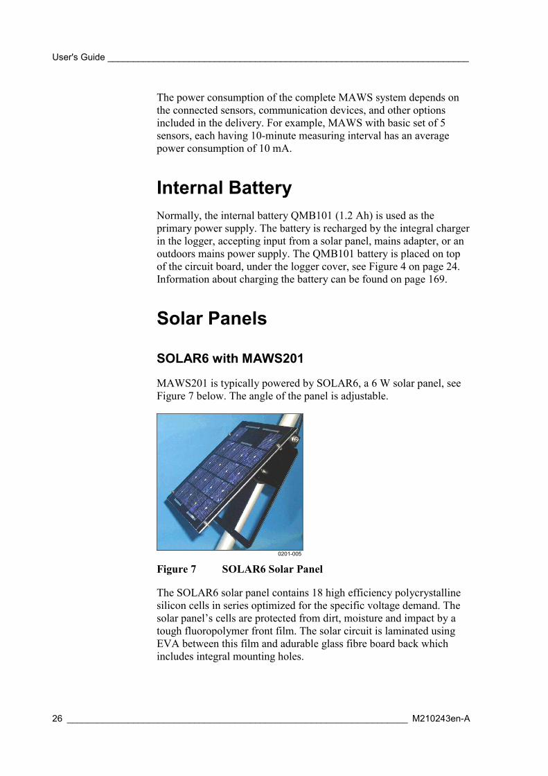
MAWS201 is typically powered by SOLAR6, a 6 W solar panel, seeFigure 7 below. The angle of the panel is adjustable.
0201-005
Figure 7 SOLAR6 Solar Panel
The SOLAR6 solar panel contains 18 high efficiency polycrystallinesilicon cells in series optimized for the specific voltage demand. Thesolar panel’s cells are protected from dirt, moisture and impact by atough fluoropolymer front film. The solar circuit is laminated usingEVA between this film and adurable glass fibre board back whichincludes integral mounting holes.
Chapter 2 ___________________________________________________________Product Overview
VAISALA________________________________________________________________________ 27
SOLAR6-75 with MAWS101
MAWS101 can be powered by SOLAR6-75, a 6 W solar panel.SOLAR6-75 is especially designed for installation on a pole mast of60-100 mm diameter. In addition to SOLAR6, the solar powerpackage includes mast mounting accessories and a 6-meter cable withthe connector. The angle of the panel is adjustable.
Mains Power SuppliesIf AC power (230 or 115 VAC) is available on the installation site,and/or solar power is not feasible, an optional mains power supply canbe used to charge the battery. For more information about connectingthe power supplies, see the instructions on page 69.
A Wall Adapter
A usual wall adapter (110/230 VAC, output min. 12 V/500 mA) canbe used when the distance to the MAWS station is less than 100 m,provided that the wall adapter can be installed indoors.
NOTE When the power cable resistance exceeds 10 Ω, a capacitor (from 100to 200 µF, 40 V) should be added between GND and +ExtDC pins.Make sure the polarity is correct.
QMP213
QMP213 is an outdoors power supply for installations where the ACpower is available. The input may vary from 90 to 264 VAC with afrequency of 50 or 60 Hz. The power consumption is 1 A. The outputprovides 12 VDC, 2.5 A.

User's Guide _______________________________________________________________________
28 ___________________________________________________________________ M210243en-A
0201-006
Figure 8 QMP213 Mains Power Supply
QMP201C
QMP201C is a power supply for installations where more power andback-up capacity are needed. Additionally, QMPC201C can provide12 V supply voltage required for example for optional radio modemset. QMP201C includes the following internal modules: the 12 Wsolar panel, battery regulator, mains power supply and 7 Ah back-upbattery. The unit is easily mounted to the tripod's leg.
0201-007
Figure 9 QMP201C Solar/Mains Power Supply

Chapter 2 ___________________________________________________________Product Overview
VAISALA________________________________________________________________________ 29
QBR101 Battery RegulatorQBR101 Battery Regulator is a charging and supervising equipmentfor 12/24 Volts lead acid and nickel-cadmium batteries. QBR101allows simultaneous input from both a solar panel and AC power.
0105-007
Figure 10 QBR101 Battery Regulator
The maximum charging current can be set by the internal jumpersettings between 0.5 to 2.5 A being applicable for battery capacity of 4to 72 Ah. The self-consumption from the battery is very low, less than0.2 mA, which is required at installations at remote locations.
Also included are LED lamps that indicate the conditions. In order tomaximize autonomy time, the lamps are activated only while pressingthe ON button.
BWT15SX Mains Power SupplyThe Mains power supply unit BWT15SX is a switching power supply,which operates from the universal AC input of 85 to 264 VAC andfrom 47 to 440 Hz. The output voltage is 15 VDC, which is used forpowering the MAWS system, and as an input to the QBR101 batteryregulator for charging the backup battery.

User's Guide _______________________________________________________________________
30 ___________________________________________________________________ M210243en-A
Sensors
Wind Sensor
0201-008
Figure 11 QMW101 Wind Sensor
QMW101 and QMW110 are compact sized wind sensors with thewind speed and direction sensors integrated into one unit. A singlecompact sensor is ideal for low-power applications. The rotating cupanemometer at the top of the unit provides isotropic and linearresponse to wind speed. The vane attached to the body of the unitprovides fast response to wind direction. Direction is detected usingan axial symmetric rotating potentiometer with two slides, thusproviding a full range from 0 to 360°, while speed is converted intopulses using dual reed relay.
The cup wheel shape, dimensions and material have been carefullydesigned to achieve maximum quality of measurement. The conicalcups have been tested to give linear response between wind speed andangular velocity of the cup wheel. The polyamide plastic reinforcedwith carbon fiber guarantees a rigid structure even at the highest windspeeds.
The balanced wind vane is integrated in the housing, underneath thecup wheel. The circular tail is located far enough from the body andthe cup wheel to avoid turbulences due to these structures. The vaneassembly is of PA (reinforced with glass fiber) providing durable andlightweight structure with fast response and low inertia.

Chapter 2 ___________________________________________________________Product Overview
VAISALA________________________________________________________________________ 31
Air Temperature and RelativeHumidity Sensor
0105-015
Figure 12 QMH101 Temperature and Relative HumiditySensor
The QMH101 Relative Humidity and Temperature Sensor is based onVaisala's field-proven HMP45D probe and comes with a special cableand connector. For humidity measurements, the HUMICAP sensor ishighly accurate and offers excellent long-term stability in a wide rangeof environments. Temperature measurements are taken by an accuratePt-100 IEC751, 1/3 Class B. Field calibration is easy with one or tworeferences. The replacement is simple; the probe head containing theelectronics can be quickly removed from the probe body, while areplacement is installed and the measurement continues. Meanwhilethe other probe head is calibrated.
The probe is installed in a naturally aspirated shield made of injectionmoulded UV stabilized plastic. The shield has multiplate designproviding the necessary shielding from solar radiation andprecipitation.

User's Guide _______________________________________________________________________
32 ___________________________________________________________________ M210243en-A
Pressure Sensor
9901-020
Figure 13 PMT16A Pressure Sensor
The silicon capacitive pressure sensor PMT16A has excellentaccuracy, repeatability and long-term stability over a wide range ofoperating temperatures. Therefore, it maintains its accuracy andcalibration for long periods of time, thus reducing the need for fieldcalibrations.
The fine adjustment and calibration of the sensor at the factory arehandled according to the electronic working standards, which arebased on international standards.
Precipitation Sensors
QMR101
0201-009
Figure 14 QMR101 Rain Gauge
The QMR101 Precipitation Sensor is economical and accurate raingauge of plastic material which is highly resistant to UV-radiation and
Chapter 2 ___________________________________________________________Product Overview
VAISALA________________________________________________________________________ 33
even frostproof. QMR101 has a self-emptying tipping spoon of 0.2millimeters capacity. Due its small size, lightweight and ruggeddesign, it is especially suitable for portable applications and temporaryinstallations. QMR101 is installed on the sensor cross arm, and hasready-made cable with the connector.
QMR102
0105-016
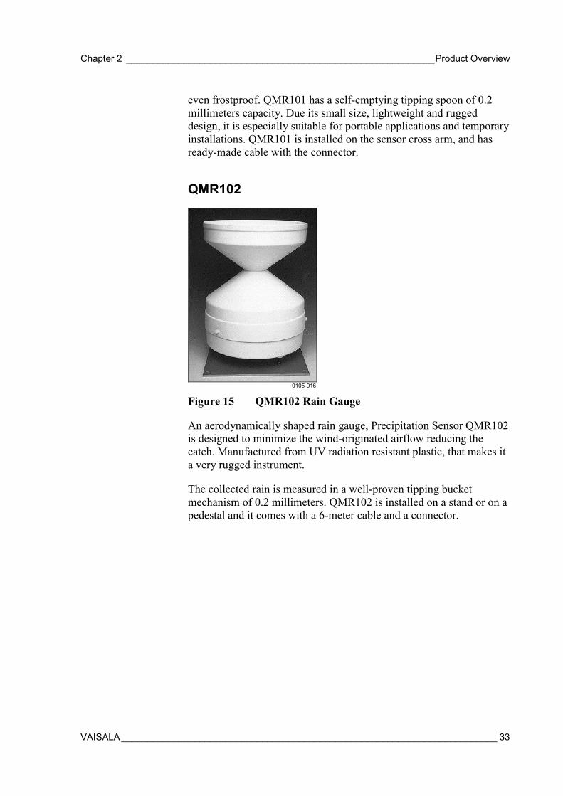
Figure 15 QMR102 Rain Gauge
An aerodynamically shaped rain gauge, Precipitation Sensor QMR102is designed to minimize the wind-originated airflow reducing thecatch. Manufactured from UV radiation resistant plastic, that makes ita very rugged instrument.
The collected rain is measured in a well-proven tipping bucketmechanism of 0.2 millimeters. QMR102 is installed on a stand or on apedestal and it comes with a 6-meter cable and a connector.

User's Guide _______________________________________________________________________
34 ___________________________________________________________________ M210243en-A
Solar Radiation Sensors
QMS101
0105-020
Figure 16 QMS101 Pyranometer
The QMS101 pyranometer is used for measuring global solarradiation. QMS101 uses a photodiode detector for creating a voltageoutput proportional to the incoming radiation. Due to the uniquedesign of the diffuser, its sensitivity is proportional to the cosine of theangle of incidence of the radiation, thus allowing accurate andconsistent measurements. QMS101 has a ready-made cable with aconnector, and it is easily installed on the sensor support arm.
QMS102
0105-021
Figure 17 QMS102 Pyranometer
QMS102 Pyranometer is an ISO/WMO-classified second classpyranometer. The precision optical glass dome acts as a filter, with aspectral band-pass that permits the full solar spectrum to pass through
Chapter 2 ___________________________________________________________Product Overview
VAISALA________________________________________________________________________ 35
to the sensor. The sensor is a high-quality blackened thermopile with aflat spectral response. Heating of the sensor by incoming solarradiation produces a signal in the microvolt range.
QMN101
0105-024
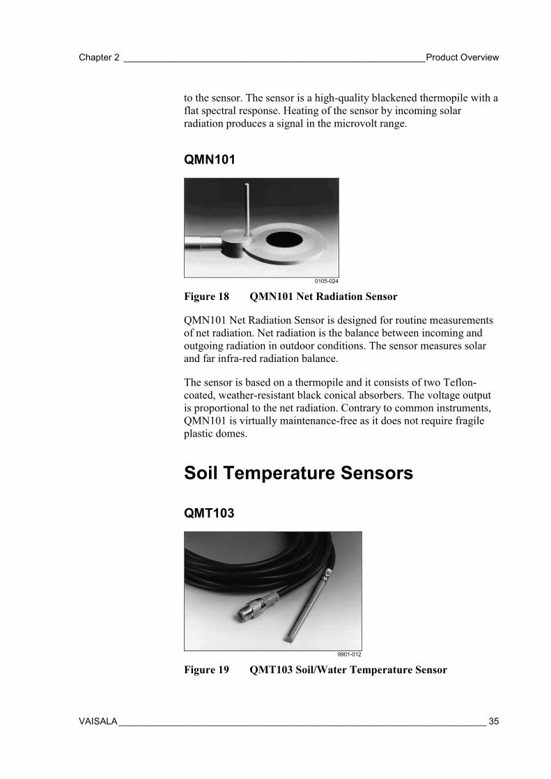
Figure 18 QMN101 Net Radiation Sensor
QMN101 Net Radiation Sensor is designed for routine measurementsof net radiation. Net radiation is the balance between incoming andoutgoing radiation in outdoor conditions. The sensor measures solarand far infra-red radiation balance.
The sensor is based on a thermopile and it consists of two Teflon-coated, weather-resistant black conical absorbers. The voltage outputis proportional to the net radiation. Contrary to common instruments,QMN101 is virtually maintenance-free as it does not require fragileplastic domes.
Soil Temperature Sensors
QMT103
9901-012
Figure 19 QMT103 Soil/Water Temperature Sensor

User's Guide _______________________________________________________________________
36 ___________________________________________________________________ M210243en-A
QMT103 Temperature Probe is particularly intended for precisionmeasurement of ground and soil temperatures. All the materials havebeen carefully selected to withstand various environmental stress andwide temperature range. The measurement accuracy and stability ofthe temperature probe are based on a Pt-100 type sensor elementspecified to 1/4 DIN 43760B preciseness level. The probe includes a5-meter cable with a black, weather-resistant polyurethane (PUR)sheath, which can tolerate both abrasive wear and extremetemperatures. Molded to the other end of the cable there is a 5-pinwatertight connector, providing for instant assembly and replacement.
QMT107
0106-041
Figure 20 QMT107 Soil Temperature Sensor
The QMT107 probe is designed for the measurement of soiltemperature and temperature profiles as a function of depth.Temperature measurement is based on resistive platinum sensors (Pt-100). There are seven temperature sensors located inside the probe.The sensors are positioned to +5 cm, ±0 cm, -5 cm, -10 cm, -20 cm, -50 cm, and -100 cm levels, where ±0 cm corresponds to the groundlevel mark of the probe.
The probe is constructed of glass fiber tube filled with epoxy, whichmakes the design watertight and provides low thermal conductivity.This ensures maximum accuracy as the sensor itself consumes verylittle power, thus causing almost no self-heating.

Chapter 2 ___________________________________________________________Product Overview
VAISALA________________________________________________________________________ 37
Soil Moisture Sensor
0105-026
Figure 21 ML2x Soil Moisture Sensor
ML2x Soil Moisture Sensor features a new technique with theaccuracy of ± 2 % soil moisture.
Traditional low cost sensors made of gypsum block dissolve even in ashort period of time when exposed to high moisture. The ML2xsensors are very durable. The rods are 60 mm long, made of resilient,solid stainless steel, and can be unscrewed and replaced if necessary.All exposed materials are either stainless steel or durable plastic, andthe probes are fully sealed. This way they can also safely be buriedinto the ground.
The ML2x probes offer high accuracy and extended lifetime inpermanent or temporary measurements of soil moisture.
Water Level Sensors
QMV101
0105-028
Figure 22 QMV101 Water Level Sensor
User's Guide _______________________________________________________________________
38 ___________________________________________________________________ M210243en-A
QMV101 Water Level Sensor determines water level by measuringthe water pressure above the submerged sensor in reservoirs, lakes,and rivers. The pressure measurement is based on high performancemicro-machined silicon technology, packaged in a fully welded 316stainless steel assembly.
The specific features include a Kevlar strain relieved vented cable,internal condensation protection and an IP68 injection molded cableassembly, which guarantees sensor operation over an extended periodof time.
QMV102
0105-029
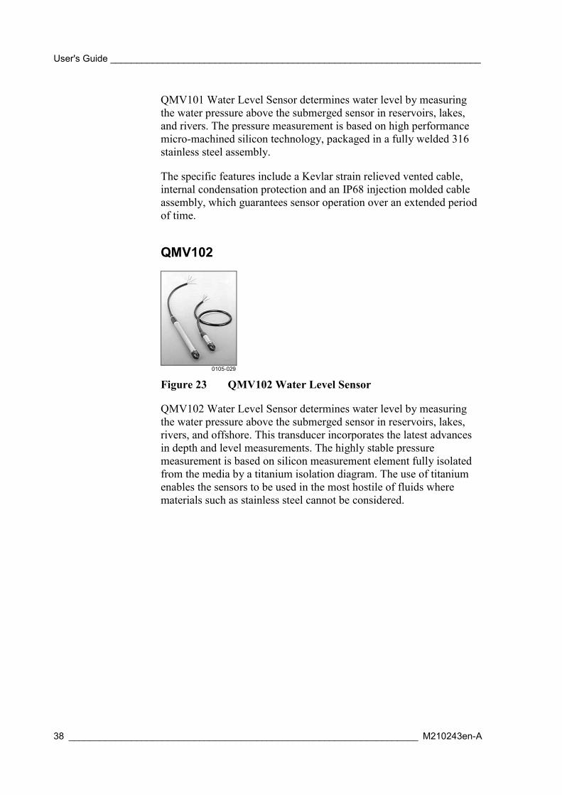
Figure 23 QMV102 Water Level Sensor
QMV102 Water Level Sensor determines water level by measuringthe water pressure above the submerged sensor in reservoirs, lakes,rivers, and offshore. This transducer incorporates the latest advancesin depth and level measurements. The highly stable pressuremeasurement is based on silicon measurement element fully isolatedfrom the media by a titanium isolation diagram. The use of titaniumenables the sensors to be used in the most hostile of fluids wherematerials such as stainless steel cannot be considered.
Chapter 2 ___________________________________________________________Product Overview
VAISALA________________________________________________________________________ 39
Leaf Wetness Sensor
0105-027
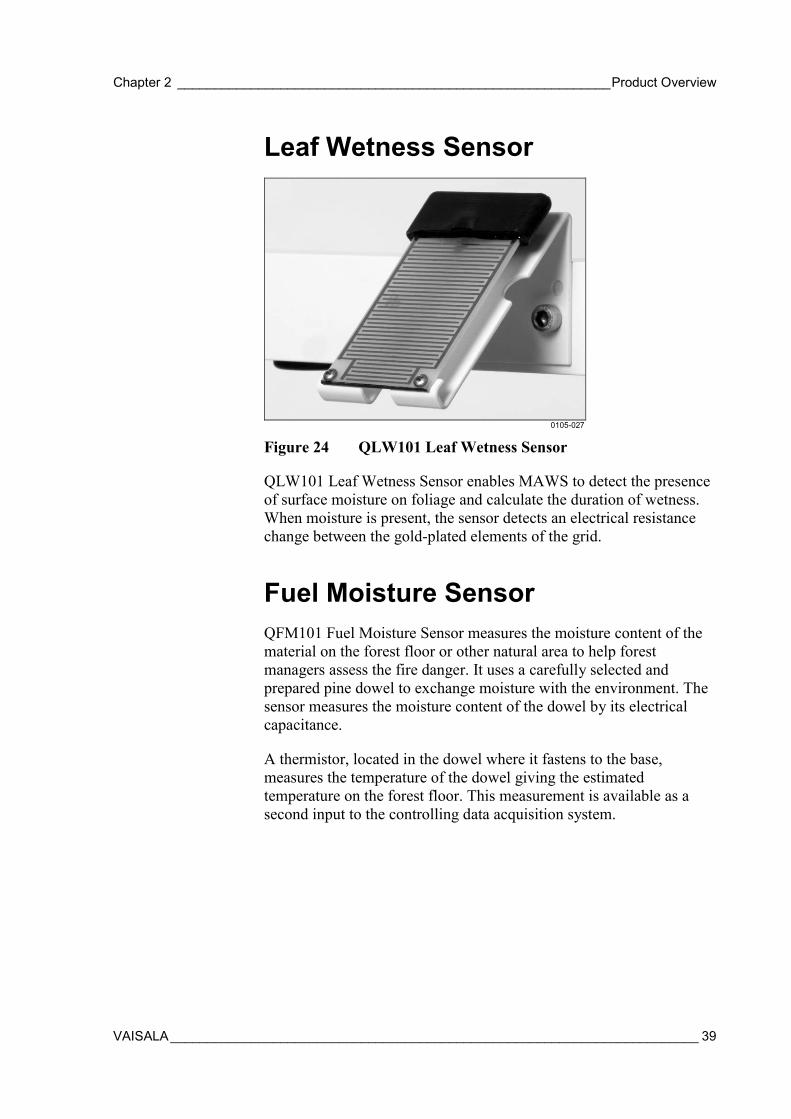
Figure 24 QLW101 Leaf Wetness Sensor
QLW101 Leaf Wetness Sensor enables MAWS to detect the presenceof surface moisture on foliage and calculate the duration of wetness.When moisture is present, the sensor detects an electrical resistancechange between the gold-plated elements of the grid.
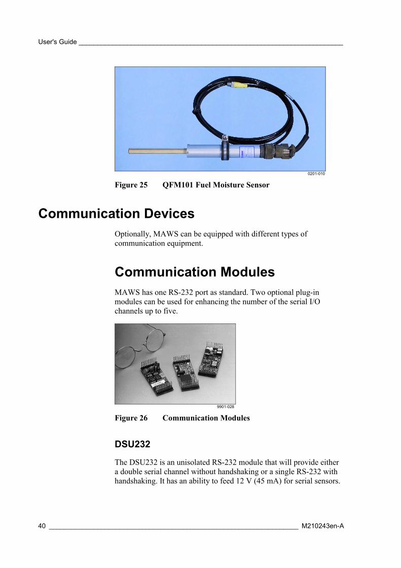
Fuel Moisture SensorQFM101 Fuel Moisture Sensor measures the moisture content of thematerial on the forest floor or other natural area to help forestmanagers assess the fire danger. It uses a carefully selected andprepared pine dowel to exchange moisture with the environment. Thesensor measures the moisture content of the dowel by its electricalcapacitance.
A thermistor, located in the dowel where it fastens to the base,measures the temperature of the dowel giving the estimatedtemperature on the forest floor. This measurement is available as asecond input to the controlling data acquisition system.
User's Guide _______________________________________________________________________
40 ___________________________________________________________________ M210243en-A
0201-010
Figure 25 QFM101 Fuel Moisture Sensor
Communication DevicesOptionally, MAWS can be equipped with different types ofcommunication equipment.
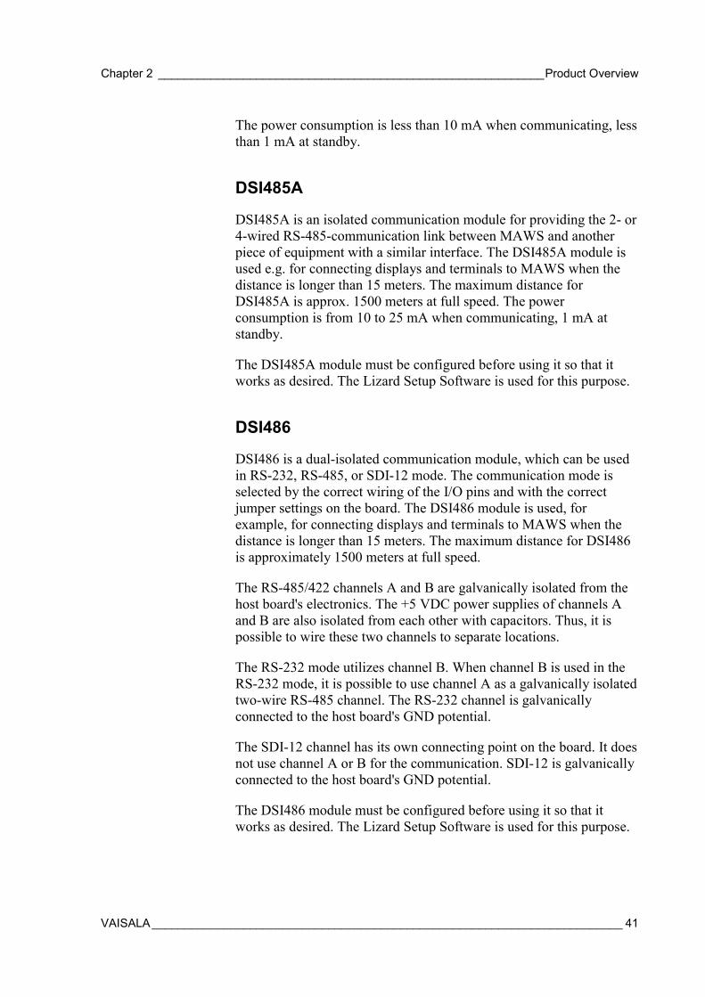
Communication ModulesMAWS has one RS-232 port as standard. Two optional plug-inmodules can be used for enhancing the number of the serial I/Ochannels up to five.
9901-028
Figure 26 Communication Modules
DSU232
The DSU232 is an unisolated RS-232 module that will provide eithera double serial channel without handshaking or a single RS-232 withhandshaking. It has an ability to feed 12 V (45 mA) for serial sensors.
Chapter 2 ___________________________________________________________Product Overview
VAISALA________________________________________________________________________ 41
The power consumption is less than 10 mA when communicating, lessthan 1 mA at standby.
DSI485A
DSI485A is an isolated communication module for providing the 2- or4-wired RS-485-communication link between MAWS and anotherpiece of equipment with a similar interface. The DSI485A module isused e.g. for connecting displays and terminals to MAWS when thedistance is longer than 15 meters. The maximum distance forDSI485A is approx. 1500 meters at full speed. The powerconsumption is from 10 to 25 mA when communicating, 1 mA atstandby.
The DSI485A module must be configured before using it so that itworks as desired. The Lizard Setup Software is used for this purpose.
DSI486
DSI486 is a dual-isolated communication module, which can be usedin RS-232, RS-485, or SDI-12 mode. The communication mode isselected by the correct wiring of the I/O pins and with the correctjumper settings on the board. The DSI486 module is used, forexample, for connecting displays and terminals to MAWS when thedistance is longer than 15 meters. The maximum distance for DSI486is approximately 1500 meters at full speed.
The RS-485/422 channels A and B are galvanically isolated from thehost board's electronics. The +5 VDC power supplies of channels Aand B are also isolated from each other with capacitors. Thus, it ispossible to wire these two channels to separate locations.
The RS-232 mode utilizes channel B. When channel B is used in theRS-232 mode, it is possible to use channel A as a galvanically isolatedtwo-wire RS-485 channel. The RS-232 channel is galvanicallyconnected to the host board's GND potential.
The SDI-12 channel has its own connecting point on the board. It doesnot use channel A or B for the communication. SDI-12 is galvanicallyconnected to the host board's GND potential.
The DSI486 module must be configured before using it so that itworks as desired. The Lizard Setup Software is used for this purpose.

User's Guide _______________________________________________________________________
42 ___________________________________________________________________ M210243en-A
Modem DMX501
The DMX501 communication module is used for providing longdistance fixed line connection between MAWS and another Vaisalaequipment with a similar interface, max. distance up to 10 km..Through this I/O port, MAWS can send reports and data or the hostcan poll them.
The DMX501 modem module supports the following communicationstandards:
- V.21, 300 bps FSK
- V.23, 1200 / 75 bps FSK
- V.22, 1200 bps DPSK
The DMX501 modem module must be configured before using it sothat it works as desired. The Lizard Setup Software is used for thispurpose.
SATELLINE 3AS Radio Modem
0201-011
Figure 27 SATELLINE 3AS Radio Modem
The SATELLINE 3AS radio modem is a half-duplex radio modemsuitable for high-speed data applications. As an UHF radio modem, itprovides the data speeds 19200 bps at 25 kHz and 9600 bps at 12.5kHz in the air. RS interface data speed is user selectable from 300 to38400 bps. The connection between MAWS and the radio modem isestablished by using RS-232. The radio modem comes with a ready-made cable (approx. 0.5 m) and a special weatherproof enclosure.

Chapter 2 ___________________________________________________________Product Overview
VAISALA________________________________________________________________________ 43
SATELLINE 3AS radio requires 12 VDC voltage for powering,therefore a mains power supply or QMP201C must be used with theradio modem. In addition, a wiring change must be made in thelogger. For details, see the installation instructions. The SATELLINE3AS radio modem must be configured before using it so that it worksas desired. The provided setup software is used for this purpose.
Accessories
Masts for MAWS101
0105-009
Figure 28 Installation Mast with Accessories
DKP102
DKP102 is a 2-m high pole mast designed for MAWS101 system.When using DKP102 mast, the wind sensor must be QMW101.Together with wind sensor installation pole, the total height of thewind sensor will be approximately 3 meters.

User's Guide _______________________________________________________________________
44 ___________________________________________________________________ M210243en-A
DKP12
DKP12 is a 10-meter pole mast used for equipment installation. Themast is made of anodized aluminum resisting well even the most harshweather condition. The mast is equipped with a lightning rod and a setof guy wires. The mast base and the guy wires require a solid concretebase. The recommended grounding resistance is less than 10 ohms.
Sensor Arm
0201-012
Figure 29 QMA101 Sensor Arm
Sensors are installed on the QMA101 sensor arm. The arm includesfactory made drillings for every sensor model to be installed. InMAWS201 totally three sensor arms can be installed to the tube. InMAWS101 totally five sensor arms can be installed.
Carry Case SetsThe carry cases for the Vaisala MAWS201 are made of cellularpolypropylene (EPP). This lightweight but very rugged materialprovides excellent cushioning during transport. The cases areequipped with handles, hinges and latches for which padlocks can beused. The larger case for the tripod is also equipped with a pair ofwheels. There are two sets of carry cases to choose from.
QMM110
The QMM110 Basic Set consists of one hard case for the sensors andaccessories, and one soft canvas case for the tripod, solar panel, windmast, as well as hammer and ground pegs.
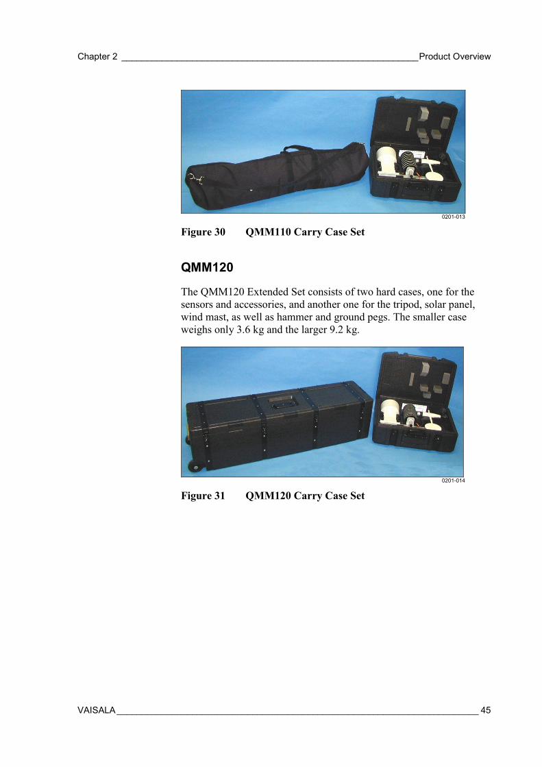
Chapter 2 ___________________________________________________________Product Overview
VAISALA________________________________________________________________________ 45
0201-013
Figure 30 QMM110 Carry Case Set
QMM120
The QMM120 Extended Set consists of two hard cases, one for thesensors and accessories, and another one for the tripod, solar panel,wind mast, as well as hammer and ground pegs. The smaller caseweighs only 3.6 kg and the larger 9.2 kg.
0201-014
Figure 31 QMM120 Carry Case Set

User's Guide _______________________________________________________________________
46 ___________________________________________________________________ M210243en-A
This page intentionally left blank.

Chapter 3 ________________________________________________________________ Installation
VAISALA________________________________________________________________________ 47
CHAPTER 3
INSTALLATION
This chapter describes how to mechanically put together a MAWSweather station that is mounted to a portable mast or to a pole mast.For the installation instructions of the MAWS Terminal software andthe setup software MAWS Lizard, see the User's Guides listed inTable 2 on page 15.
Table 8 Overview of InstallationSection Questions answeredIntroduction to MAWS, on page17
What is a MAWS station made of? Howare the parts called in this manual?
Preparing Installation, below What tools are needed, how to unpackthe delivery?
Siting the Station, on page 48 Where to install the station and thesensors?
Installing MAWS BasicComponents, on page 53
How to assemble basic components?
Installing MAWS101 to a Mast,on page 57
How to install MAWS101 to a polemast?
Installing MAWS201 to theTripod, on page 62
How to install MAWS201 to the tripod?How to set up a mobile station aftertransportation?
Disassembly of MAWS201 forTransportation, on page 97
How to pack MAWS for transportation?
Preparing InstallationMake sure you have all the necessary tools at hand. The Tools Bagsupplied with the tripod mast includes a set of tools that will beneeded during installation.
User's Guide _______________________________________________________________________
48 ___________________________________________________________________ M210243en-A
Tools needed:
- Compass (not supplied), or other methods to establish the rightorientation of the station
- Screwdrivers: 3 mm (in the Tools Bag)
- Hex wrenches: 4 mm (in the Tools Bag)
- Hammer for hitting the ground pegs into ground (in the Tools Bagof the MAWS201 delivery)
- Pegs for securing the tripod (in the Tools Bag of the MAWS201delivery).
Additional special tools for the different sensors are provided in theirpackages.
One person can complete the whole installation. Depending on the setof sensors, the installation should not take more than half an hour.
Unpacking InstructionsWhen you have received the delivery, first see that you have all theordered components. Secondly, check the sensors. Make sure are thatthey have not been damaged during transportation.
User manuals and special tools included in the packages should bestored in a safe place for later use.
The logger electronics are attached to the railing inside the tube. Alsothe tripod is already assembled, but needs to be attached to the tubestructure (see Assembling the Tripod on page 63).
Siting the StationFinding a suitable site for the weather station is important for gettingrepresentative ambient measurements. Normally, the suitable siteshould represent the general area of interest. When locating theweather station, consider the items presented in the following sections.The descriptions are not exhaustive, for further information refer tolocal and WMO recommendations.

Chapter 3 ________________________________________________________________ Installation
VAISALA________________________________________________________________________ 49
WindAllow sufficient clearance for the wind sensors, that is, the stationshould not be located next to a building or any other object that mightaffect the airflow.
0201-015
Figure 32 Siting the Station
In general, any object of height h will not remarkably disturb the windmeasurement at a minimum distance of 10×h. For example, locate theweather station at least 30 meters away from a 3-meter high tree. SeeFigure 32 above.
Air Temperature and RelativeHumidity
NOTE The radiation shield is important in protecting the sensor from directsunlight and must always be used.
For MAWS201, a suitable height for the sensor is already determinedby the tripod. For MAWS101 in mast installations, the height shouldbe set to 1.5 to 2 meters. In the northern hemisphere, the sensor shouldusually be on the northern side of the mast. Avoid the followinginstallation sites to ensure correct measurements: shaded areas,
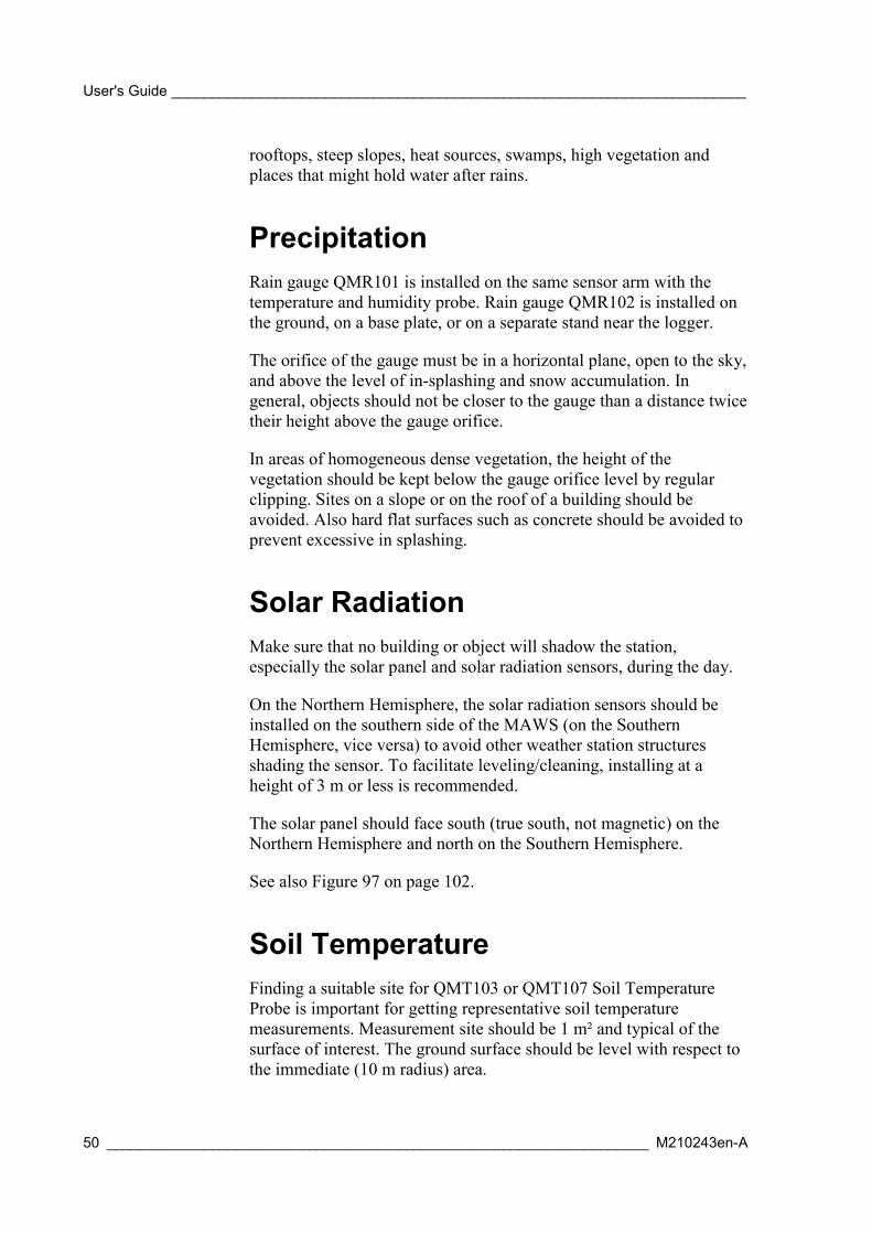
User's Guide _______________________________________________________________________
50 ___________________________________________________________________ M210243en-A
rooftops, steep slopes, heat sources, swamps, high vegetation andplaces that might hold water after rains.
PrecipitationRain gauge QMR101 is installed on the same sensor arm with thetemperature and humidity probe. Rain gauge QMR102 is installed onthe ground, on a base plate, or on a separate stand near the logger.
The orifice of the gauge must be in a horizontal plane, open to the sky,and above the level of in-splashing and snow accumulation. Ingeneral, objects should not be closer to the gauge than a distance twicetheir height above the gauge orifice.
In areas of homogeneous dense vegetation, the height of thevegetation should be kept below the gauge orifice level by regularclipping. Sites on a slope or on the roof of a building should beavoided. Also hard flat surfaces such as concrete should be avoided toprevent excessive in splashing.
Solar RadiationMake sure that no building or object will shadow the station,especially the solar panel and solar radiation sensors, during the day.
On the Northern Hemisphere, the solar radiation sensors should beinstalled on the southern side of the MAWS (on the SouthernHemisphere, vice versa) to avoid other weather station structuresshading the sensor. To facilitate leveling/cleaning, installing at aheight of 3 m or less is recommended.
The solar panel should face south (true south, not magnetic) on theNorthern Hemisphere and north on the Southern Hemisphere.
See also Figure 97 on page 102.
Soil TemperatureFinding a suitable site for QMT103 or QMT107 Soil TemperatureProbe is important for getting representative soil temperaturemeasurements. Measurement site should be 1 m² and typical of thesurface of interest. The ground surface should be level with respect tothe immediate (10 m radius) area.

Chapter 3 ________________________________________________________________ Installation
VAISALA________________________________________________________________________ 51
The QMT107 probes are pressed into pre-formed holes, but they canalso be placed into excavated holes that are then filled. On hard orrocky ground, a pilot hole is pre-formed with an auger rod.
Soil MoistureThe soil water content measured by the ML2x sensor within one smalllocality can be affected by:
- Variations in soil density and composition
- Stones close to the rods
- Roots (either nearby or pierced by the rods)
- Earth worm holes or mole holes
- Subsoil drainage
- Small scale variability in transpiration and evaporation losses.
It is important to take the degree of variability of these parameters intoaccount when deciding on the number of probes to be used at anyparticular location. If the soil is known to be very heterogeneous, itwill be necessary to take measurements from at least three closely-spaced locations.
Water LevelPlace the QMV101 and QMV102 sensors according to the followingexamples. Refer to Figure 33 on page 52.
Example 1: Average water level is 25 meters and maximum annualchange is 50 cm. Suitable sensor is with range of 75 cm andinstallation place is 24,6 meter from ground level.
Example 2: In dry season the riverbed is dry and in rain season theultimate water level is 7 meters. Suitable sensor would be with 10-meter range. If interested values start after water level is greater than 3meters, it is possible to use 5-meter version and install it to 3 metersfrom ground.
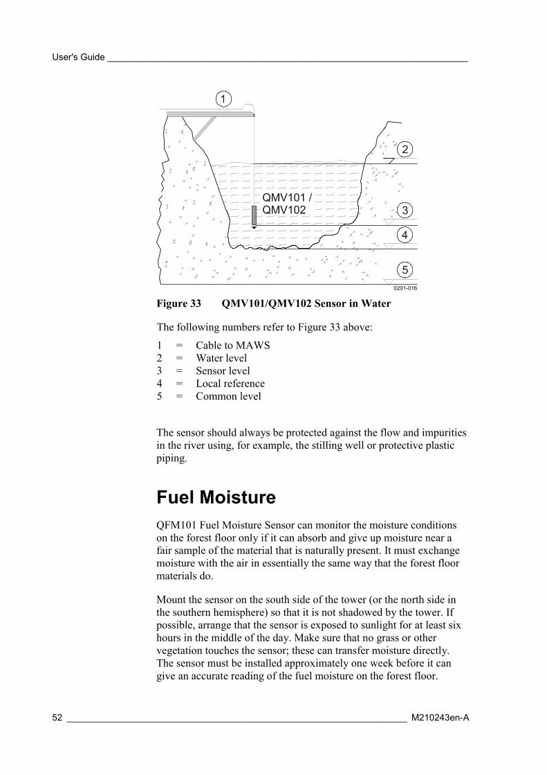
User's Guide _______________________________________________________________________
52 ___________________________________________________________________ M210243en-A
0201-016
Figure 33 QMV101/QMV102 Sensor in Water
The following numbers refer to Figure 33 above:
1 = Cable to MAWS2 = Water level3 = Sensor level4 = Local reference5 = Common level
The sensor should always be protected against the flow and impuritiesin the river using, for example, the stilling well or protective plasticpiping.
Fuel MoistureQFM101 Fuel Moisture Sensor can monitor the moisture conditionson the forest floor only if it can absorb and give up moisture near afair sample of the material that is naturally present. It must exchangemoisture with the air in essentially the same way that the forest floormaterials do.
Mount the sensor on the south side of the tower (or the north side inthe southern hemisphere) so that it is not shadowed by the tower. Ifpossible, arrange that the sensor is exposed to sunlight for at least sixhours in the middle of the day. Make sure that no grass or othervegetation touches the sensor; these can transfer moisture directly.The sensor must be installed approximately one week before it cangive an accurate reading of the fuel moisture on the forest floor.

Chapter 3 ________________________________________________________________ Installation
VAISALA________________________________________________________________________ 53
Installing MAWS Basic ComponentsThe installation of the basic components is done only when taking theMAWS weather station in use for the first time. Some of the steps areapplicable also in the normal use of the portable MAWS201 station.
NOTE The figures in the procedure are taken from installing the MAWS201.In case you are installing MAWS101, you do not have any of thetripod's parts attached as shown in some of the figures.
1. Loosen and remove two hand screws (1) beneath the tube. Slidethe tube (2) down to expose the logger.
0201-017
Figure 34 Tube Securing Hand Screws
2. Remove the logger cover screw (1) to open the logger housing.
0201-018
Figure 35 Logger Cover Screw
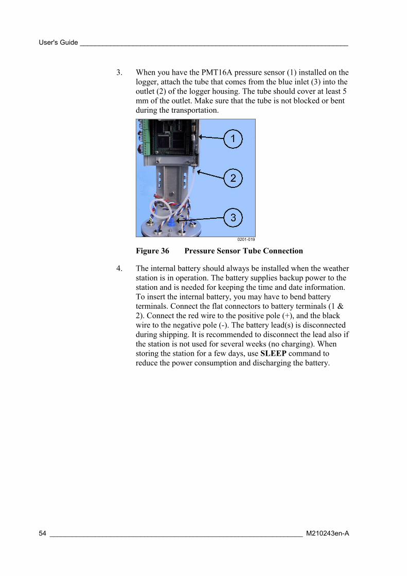
User's Guide _______________________________________________________________________
54 ___________________________________________________________________ M210243en-A
3. When you have the PMT16A pressure sensor (1) installed on thelogger, attach the tube that comes from the blue inlet (3) into theoutlet (2) of the logger housing. The tube should cover at least 5mm of the outlet. Make sure that the tube is not blocked or bentduring the transportation.
0201-019
Figure 36 Pressure Sensor Tube Connection
4. The internal battery should always be installed when the weatherstation is in operation. The battery supplies backup power to thestation and is needed for keeping the time and date information.To insert the internal battery, you may have to bend batteryterminals. Connect the flat connectors to battery terminals (1 &2). Connect the red wire to the positive pole (+), and the blackwire to the negative pole (-). The battery lead(s) is disconnectedduring shipping. It is recommended to disconnect the lead also ifthe station is not used for several weeks (no charging). Whenstoring the station for a few days, use SLEEP command toreduce the power consumption and discharging the battery.
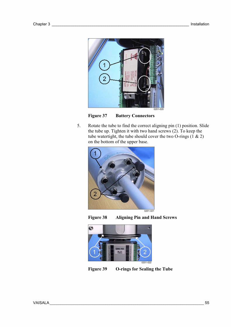
Chapter 3 ________________________________________________________________ Installation
VAISALA________________________________________________________________________ 55
0201-020
Figure 37 Battery Connectors
5. Rotate the tube to find the correct aligning pin (1) position. Slidethe tube up. Tighten it with two hand screws (2). To keep thetube watertight, the tube should cover the two O-rings (1 & 2)on the bottom of the upper base.
0201-021
Figure 38 Aligning Pin and Hand Screws
0201-022
Figure 39 O-rings for Sealing the Tube
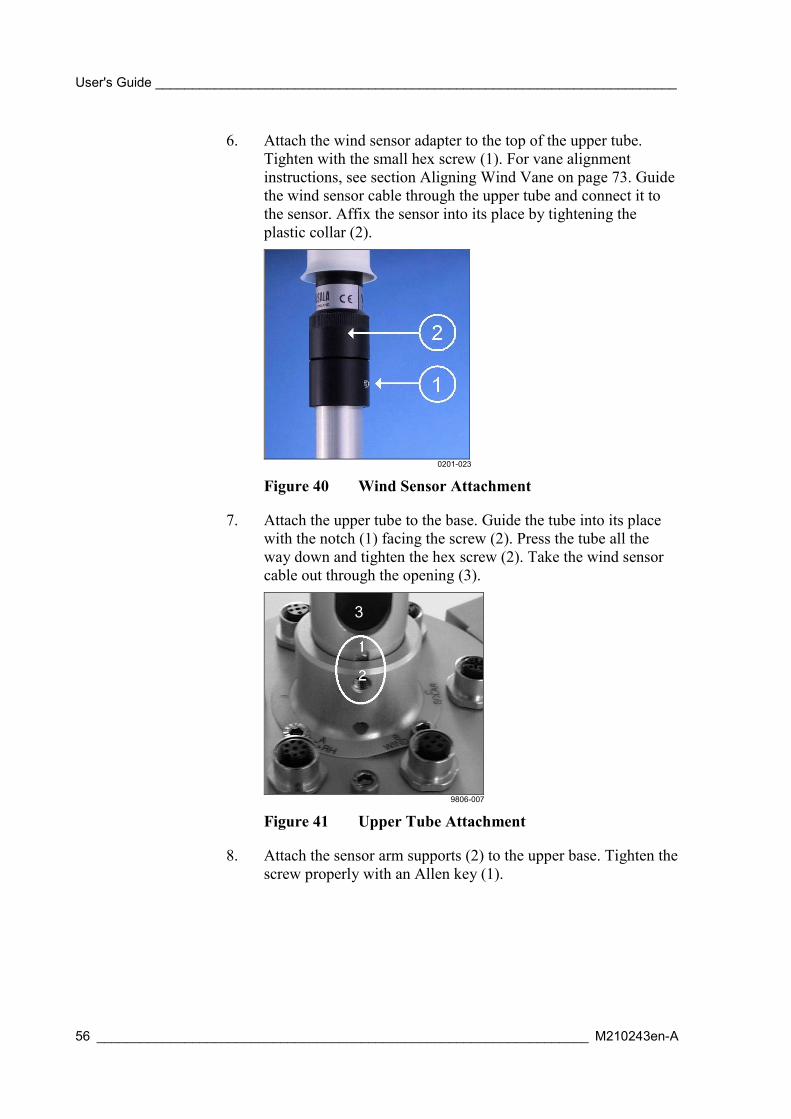
User's Guide _______________________________________________________________________
56 ___________________________________________________________________ M210243en-A
6. Attach the wind sensor adapter to the top of the upper tube.Tighten with the small hex screw (1). For vane alignmentinstructions, see section Aligning Wind Vane on page 73. Guidethe wind sensor cable through the upper tube and connect it tothe sensor. Affix the sensor into its place by tightening theplastic collar (2).
0201-023
Figure 40 Wind Sensor Attachment
7. Attach the upper tube to the base. Guide the tube into its placewith the notch (1) facing the screw (2). Press the tube all theway down and tighten the hex screw (2). Take the wind sensorcable out through the opening (3).
3
9806-007
Figure 41 Upper Tube Attachment
8. Attach the sensor arm supports (2) to the upper base. Tighten thescrew properly with an Allen key (1).

Chapter 3 ________________________________________________________________ Installation
VAISALA________________________________________________________________________ 57
0201-024
Figure 42 Sensor Arm Support Attachment
9. Attach the sensor arm(s). Fit the cables into the opening (1)before tightening the attachment screws (2 & 3). For installingthe sensors, see section Installing Sensors on page 71.
0201-025
Figure 43 Sensor Arm Assembly
Installing MAWS101 to a MastMAWS101 can be installed in several ways:
- Using the 2 meter high mast DKP102.
- Using the 10 meter high mast DKP12.
- Using any wooden pole or wall.
On DKP102The stud bolts and anchors for installing the mast are delivered withthe mast. Typically, the mast is installed on an existing concretefoundation (with a minimum size of 500 × 500 × 300 (mm)) or on arocky bed. Drill holes into the foundation as described in Figure 44 onpage 58. After that, fasten the stud bolts to the anchors by hand.

User's Guide _______________________________________________________________________
58 ___________________________________________________________________ M210243en-A
Protect the tops of the bolts with two nuts tightened together. Place thecombinations into the holes, anchors down, and hammer them down.Tighten the bolts a few times to ensure that the anchors attach to thewalls of the holes. Fix the pedestals with the washers and nuts.
Alternatively, the stud bolts can be encased in concrete. In this case,the bolts should be kept safely at the correct position during pouringthe concrete in. You should also protect the stud bolts from theconcrete during casting to avoid problems in installing the pedestals.
0201-026
Figure 44 DKP12 Attachment to a Foundation
The following numbers refer to Figure 44 above.
1 = Mast2 = Pedestals 2 pcs3 = Nuts M10 DIN934 8 pcs
Washers A10.5 DIN125 8 pcs4 = Stud bolts M10x200 4 pcs5 = Anchor M10 L=40 4 pcs6 = Bolts M10x90 DIN933 2 pcs
Washers A10.5 DIN125 4 pcsNuts M10 DIN934 2 pcs
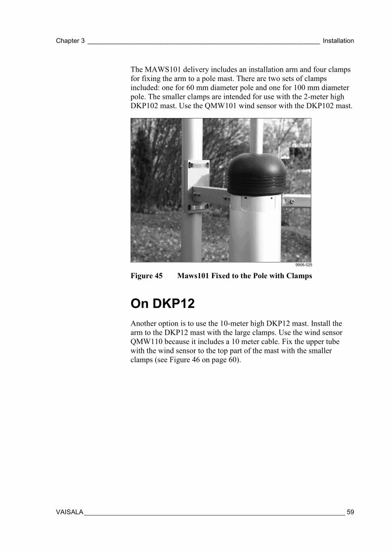
Chapter 3 ________________________________________________________________ Installation
VAISALA________________________________________________________________________ 59
The MAWS101 delivery includes an installation arm and four clampsfor fixing the arm to a pole mast. There are two sets of clampsincluded: one for 60 mm diameter pole and one for 100 mm diameterpole. The smaller clamps are intended for use with the 2-meter highDKP102 mast. Use the QMW101 wind sensor with the DKP102 mast.
9906-025
Figure 45 Maws101 Fixed to the Pole with Clamps
On DKP12Another option is to use the 10-meter high DKP12 mast. Install thearm to the DKP12 mast with the large clamps. Use the wind sensorQMW110 because it includes a 10 meter cable. Fix the upper tubewith the wind sensor to the top part of the mast with the smallerclamps (see Figure 46 on page 60).

User's Guide _______________________________________________________________________
60 ___________________________________________________________________ M210243en-A
9908-003
Figure 46 Wind Sensor QMW110 with DKP12 Mast
The 10-m cable is used for connecting the wind sensor to theconnector "Wind" on the upper base of the MAWS. A protectivecover screw, included in the shipment, holds the protective cover inplace above the upper base (see Figure 47 below).
9910-015
Figure 47 Installing the Protective cover Screw

Chapter 3 ________________________________________________________________ Installation
VAISALA________________________________________________________________________ 61
On Any Wooden Pole or WallThe installation arm includes two holes for fixing the arm to anywooden pole or wall. For details, see Figure 48 below and Figure 49below.
9906-022
Figure 48 Installation Arm
9906-026
Figure 49 MAWS101 Fixed to a Wooden Pole with Screws
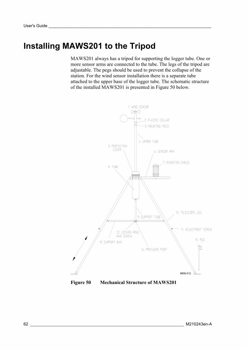
User's Guide _______________________________________________________________________
62 ___________________________________________________________________ M210243en-A
Installing MAWS201 to the TripodMAWS201 always has a tripod for supporting the logger tube. One ormore sensor arms are connected to the tube. The legs of the tripod areadjustable. The pegs should be used to prevent the collapse of thestation. For the wind sensor installation there is a separate tubeattached to the upper base of the logger tube. The schematic structureof the installed MAWS201 is presented in Figure 50 below.
9806-012
Figure 50 Mechanical Structure of MAWS201
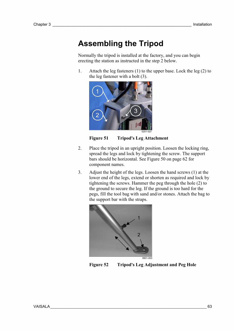
Chapter 3 ________________________________________________________________ Installation
VAISALA________________________________________________________________________ 63
Assembling the TripodNormally the tripod is installed at the factory, and you can beginerecting the station as instructed in the step 2 below.
1. Attach the leg fasteners (1) to the upper base. Lock the leg (2) tothe leg fastener with a bolt (3).
0201-027
Figure 51 Tripod's Leg Attachment
2. Place the tripod in an upright position. Loosen the locking ring,spread the legs and lock by tightening the screw. The supportbars should be horizontal. See Figure 50 on page 62 forcomponent names.
3. Adjust the height of the legs. Loosen the hand screws (1) at thelower end of the legs, extend or shorten as required and lock bytightening the screws. Hammer the peg through the hole (2) tothe ground to secure the leg. If the ground is too hard for thepegs, fill the tool bag with sand and/or stones. Attach the bag tothe support bar with the straps.
1
2
9901-003
Figure 52 Tripod's Leg Adjustment and Peg Hole

User's Guide _______________________________________________________________________
64 ___________________________________________________________________ M210243en-A
Installing Power Supply
Installing Solar PanelUsually the solar panel is installed at the factory, and you should onlyadjust the tilt angle and check that the connector is attached.
1. Locate the leg where the solar panel is to be installed. Note thealignment of sensor arms vs. solar panel. See Figure 97 on page102. Open the bolt (3) of the leg fastener (1) to release the leg(2).
0201-027
Figure 53 Tripod's Leg Attachment
2. Glide the solar panel fixture down the leg so that the fixingpiece (1) inside the leg fit over the leg profile. When the fixtureis at suitable height, tighten the screws (4). Place the panel onthe fixture and tighten the screws (3 and 5). Fit the cable (2)inside the leg and guide it through the hole in the leg fastener (1in Figure 53 above). Put the leg back into the leg fastener andtighten the bolt (3 in Figure 53 above).
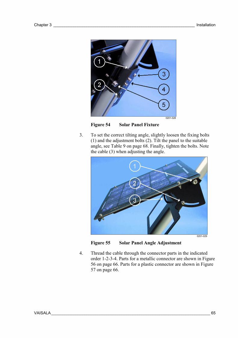
Chapter 3 ________________________________________________________________ Installation
VAISALA________________________________________________________________________ 65
0201-028
Figure 54 Solar Panel Fixture
3. To set the correct tilting angle, slightly loosen the fixing bolts(1) and the adjustment bolts (2). Tilt the panel to the suitableangle, see Table 9 on page 68. Finally, tighten the bolts. Notethe cable (3) when adjusting the angle.
0201-029
Figure 55 Solar Panel Angle Adjustment
4. Thread the cable through the connector parts in the indicatedorder 1-2-3-4. Parts for a metallic connector are shown in Figure56 on page 66. Parts for a plastic connector are shown in Figure57 on page 66.

User's Guide _______________________________________________________________________
66 ___________________________________________________________________ M210243en-A
9806-015
Figure 56 Metallic Connector for Solar Panel
0201-030
Figure 57 Plastic Connector for Solar Panel
5. Insert the wires numbered 1 and 2 into the terminal 1 and thewires numbered 3 and 4 into the terminal 3. Tighten the screwsthat hold the wires.
0201-053
Figure 58 Wires' Connection to the Terminals
NOTE In the following two figures only the metallic connector is presented,although the procedure is the same with the plastic connectors.
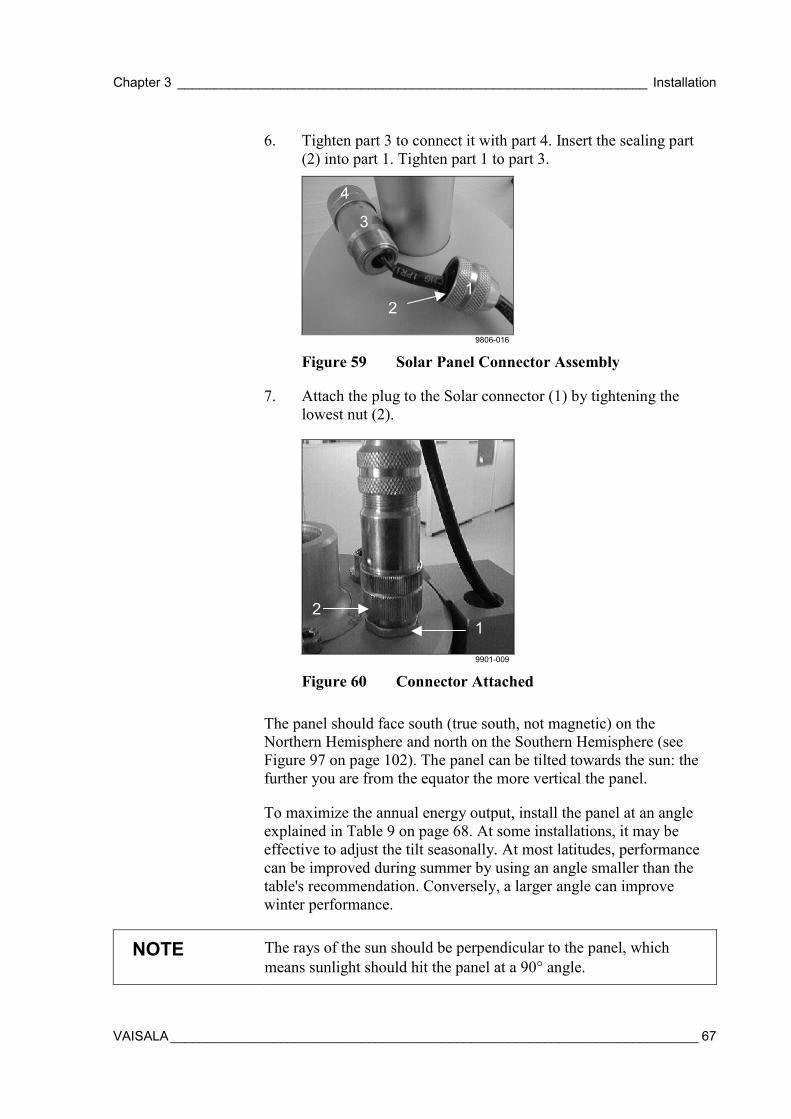
Chapter 3 ________________________________________________________________ Installation
VAISALA________________________________________________________________________ 67
6. Tighten part 3 to connect it with part 4. Insert the sealing part(2) into part 1. Tighten part 1 to part 3.
4
3
21
9806-016
Figure 59 Solar Panel Connector Assembly
7. Attach the plug to the Solar connector (1) by tightening thelowest nut (2).
21
9901-009
Figure 60 Connector Attached
The panel should face south (true south, not magnetic) on theNorthern Hemisphere and north on the Southern Hemisphere (seeFigure 97 on page 102). The panel can be tilted towards the sun: thefurther you are from the equator the more vertical the panel.
To maximize the annual energy output, install the panel at an angleexplained in Table 9 on page 68. At some installations, it may beeffective to adjust the tilt seasonally. At most latitudes, performancecan be improved during summer by using an angle smaller than thetable's recommendation. Conversely, a larger angle can improvewinter performance.
NOTE The rays of the sun should be perpendicular to the panel, whichmeans sunlight should hit the panel at a 90° angle.
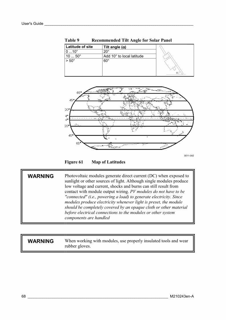
User's Guide _______________________________________________________________________
68 ___________________________________________________________________ M210243en-A
Table 9 Recommended Tilt Angle for Solar PanelLatitude of site Tilt angle (αααα)0 ...10° 20°10 ... 50° Add 10° to local latitude> 50° 60°
0011-042
Figure 61 Map of Latitudes
WARNING Photovoltaic modules generate direct current (DC) when exposed tosunlight or other sources of light. Although single modules producelow voltage and current, shocks and burns can still result fromcontact with module output wiring. PV modules do not have to be"connected" (i.e., powering a load) to generate electricity. Sincemodules produce electricity whenever light is preset, the moduleshould be completely covered by an opaque cloth or other materialbefore electrical connections to the modules or other systemcomponents are handled
WARNING When working with modules, use properly insulated tools and wearrubber gloves.

Chapter 3 ________________________________________________________________ Installation
VAISALA________________________________________________________________________ 69
CAUTION Handle with care: impact on the front or rear surface can damage themodule. Do not bend the module.
NOTE Do not concentrate light on the module in an attempt to increase itspower output.
Installing a QMP Power SupplyMAWS can be powered from a QMP power supply. For thealternatives, see section Power Supplies on page 25.
QMP213 Mains Power Supply
QMP213 Mains Power Supply is delivered with the U-bolts, washers,nuts, and the connector cable for MAWS. The unit is attached to themast.
0201-031
Figure 62 QMP213 with Installation Accessories

User's Guide _______________________________________________________________________
70 ___________________________________________________________________ M210243en-A
To install the unit, follow the procedure below:
1. Attach the unit through the holes in the upper end (1) with theprovided accessories (2) to the mast. The cable inlets shouldface down.
2. Lead the mains power cable through the opening (4) andconnect the wires under the screws into locations marked with Land N. Tighten the inlet nut properly.
3. Connect the output power cable (3) to the power connector ofMAWS, see section Connecting Cables on page 71.
QMP201C Solar/Mains Power Supply
QMP201C Solar/Mains Power Supply is delivered with a connectorcable for MAWS. The unit is attached to the tripod's leg.
0201-032
Figure 63 Parts of QMP201C
The following numbers refer to Figure 63 above.
1 = Solar Panel2 = The box for the backup battery3 = The box for the mains power supply and battery regulator4 = The angle adjusting hand screw5 = The connector cable

Chapter 3 ________________________________________________________________ Installation
VAISALA________________________________________________________________________ 71
To install the unit, follow the procedure below:
1. See section Installing Solar Panel on page 64 for mechanicalinstallation instructions.
2. Attach the cable (5 in Figure 63 on page 70) to the powerconnector of MAWS, see section Connecting Cables below.
3. Adjust the angle of the solar panel as described in sectionInstalling Solar Panel on page 64.
Installing SensorsThe mechanical installation of the sensors is presented in thefollowing sections.
Connecting CablesAfter installing the sensors mechanically, follow the instructions in thesteps below to connect the cables. Step 1 is for the lower base of thetube and step 2 is for the upper base of the tube.
NOTE Be careful when connecting cables so that the connector pins will notbend.
1. Connect the sensor cables to the connectors on the lower baseand tighten the screw nuts. For connector description, see Table10 below.
Table 10 Default Lower Base ConnectorsConnector Sensor/Device(H) COM0 Terminal(I) COM1 Communications or sensors with RS-232
interface(K) COM2 Communications or sensors with RS-232
interface(L) QMT103 or QMT107(M) Additional sensor(O) Additional sensor

User's Guide _______________________________________________________________________
72 ___________________________________________________________________ M210243en-A
2. Connect cables to the connectors on the upper base and tightenthe screw nuts. For connector description, see Table 11 below.
Table 11 Default Upper Base ConnectorsConnector Sensor/Device(A) T+RH QMH101(B) Wind QMW101(C) Solar Power supply (solar panel or mains power)(D) QMR101 or QMR102(E) QMS101 or QMS102(F) QMN101
3. Finally, lower the protection cover on the upper base to shieldthe connectors.
Installing Pressure SensorThe PMT16A Pressure Sensor is located on the CPU board of thelogger, see Figure 64 on page 73. Normally, it is factory installed onthe logger board. If necessary, it can be accessed by removing thecover of the logger. The sensor is connected directly into theconnector on the board and is fixed on it by one screw.
CAUTION When handling the sensor, take care not to bent any components onthe transducer board.
CAUTION Beware of electrostatic discharge when touching objects inside thelogger housing.
CAUTION Make sure that the vent tube of the pressure sensor is not blocked orbent during transportation.

Chapter 3 ________________________________________________________________ Installation
VAISALA________________________________________________________________________ 73
0201-033
Figure 64 PMT16A Location on the Logger
Installing Wind SensorBefore installing the sensor itself, you have to mount the wind sensormast to the upper base of the tube. After you have installed the mast,you can mount the wind sensor on top of it. For more information, seeFigure 40 on page 56.
Aligning Wind Vane
Using winddircal0 Command1. Turn the nose (1) of the vane to a known point of compass (e.g.
north).
2. Give command winddircal0 with the known direction reading(e.g. winddircal0 360. This will set the current direction to thenorth, 360 degrees).

User's Guide _______________________________________________________________________
74 ___________________________________________________________________ M210243en-A
0201-034
Figure 65 Aligning the Wind Vane
Using Compass and Reference PointWith the MAWS running, monitor the instant wind speed in thereports sent through serial line.
1. The wind sensor cable must be connected both to the sensor andto the Wind connector.
2. The mounting piece (2) must be placed on top of the upper tubeand the sensor must be attached to the mounting piece with theplastic collar (3).
3. Choose a known wind direction reference point on the horizonwith the help of a compass.
4. Point the nose of the vane at the reference point.
5. Hold the vane in position and slowly rotate the mounting pieceuntil wind direction shows proper value.
6. Secure the mounting piece to the mast by tightening themounting screw (4).

Chapter 3 ________________________________________________________________ Installation
VAISALA________________________________________________________________________ 75
Installing Air Temperature andRelative Humidity Sensor
Figure 66 QMH101 Probe and the Radiation Shield
Install the QMH101 Temperature and Relative Humidity Sensor in thefollowing way:
1. Install the radiation shield with the support on the mounting armusing the two screws.
2. Slide the temperature and humidity probe into the shield.
3. Tighten the fastening ring.
4. Guide the sensor cable through the sensor arm opening.
5. Connect the signal cable to the upper base plate of the tube. SeeTable 11 on page 72.
Installing Rain Gauges
QMR101
QMR101 is usually installed on the same sensor arm with thetemperature and humidity probe. QMR101 should be attached to asensor arm in the following way:
1. Attach the mounting plates (1) to the sensor (2), if not already inplace.

User's Guide _______________________________________________________________________
76 ___________________________________________________________________ M210243en-A
12
9806-062
Figure 67 Mounting Plates Attachment
2. Attach the rain gauge (1) to the arm with the screws (2)provided with the rain gauge.
21
9901-010
Figure 68 Rain Gauge Attachment
QMR102
Due to the low weight of the rain gauge, it must be mounted securely.QMR102 can be installed either using a specific stand RG35003 or onthe ground when it is attached to a properly anchored RGB1 base platewith provided studs. As well, the gauge can be mounted via the threeholes in the base, for example, to a paving slab. You should use rawlplugs and standard steel studs for this purpose as they provide a meansof leveling the rain gauge.
Installing on the Stand RG35003To install the gauge on the stand, follow the procedure below:
1. Attach the stand (3) to a concrete foundation with the bolts (5).See Figure 69 on page 77.
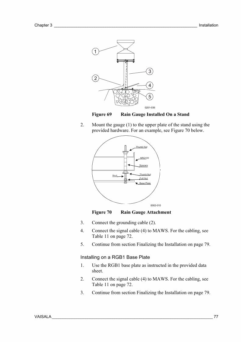
Chapter 3 ________________________________________________________________ Installation
VAISALA________________________________________________________________________ 77
0201-035
Figure 69 Rain Gauge Installed On a Stand
2. Mount the gauge (1) to the upper plate of the stand using theprovided hardware. For an example, see Figure 70 below.
0002-010
Figure 70 Rain Gauge Attachment
3. Connect the grounding cable (2).
4. Connect the signal cable (4) to MAWS. For the cabling, seeTable 11 on page 72.
5. Continue from section Finalizing the Installation on page 79.
Installing on a RGB1 Base Plate1. Use the RGB1 base plate as instructed in the provided data
sheet.
2. Connect the signal cable (4) to MAWS. For the cabling, seeTable 11 on page 72.
3. Continue from section Finalizing the Installation on page 79.

User's Guide _______________________________________________________________________
78 ___________________________________________________________________ M210243en-A
NOTE The base plate may be mounted to hard surfaces like concrete byreplacing the pegs with screws and rawl plugs. For temporarymounting on hard surfaces use heavy weights on the four corners ofthe base plate. The height of the weights should be kept as low aspossible to cause the minimum interference with the aerodynamics ofthe rain gauge.
Installing on a Pedestal1. Drill out three holes in the base to the 6.5 mm in diameter and
clean off burr. For details, see Figure 71 below.
2. For the pegs, drill out a hole in the each corner of the pedestalplate. Clean off burr.
0002-011
Figure 71 Rain Gauge Pedestal Plate Dimensions
3. Place the pedestal plate with rain gauge assembly on the groundusing the pegs supplied. If force is needed, then remove the raingauge first. See Figure 72 on page 79.
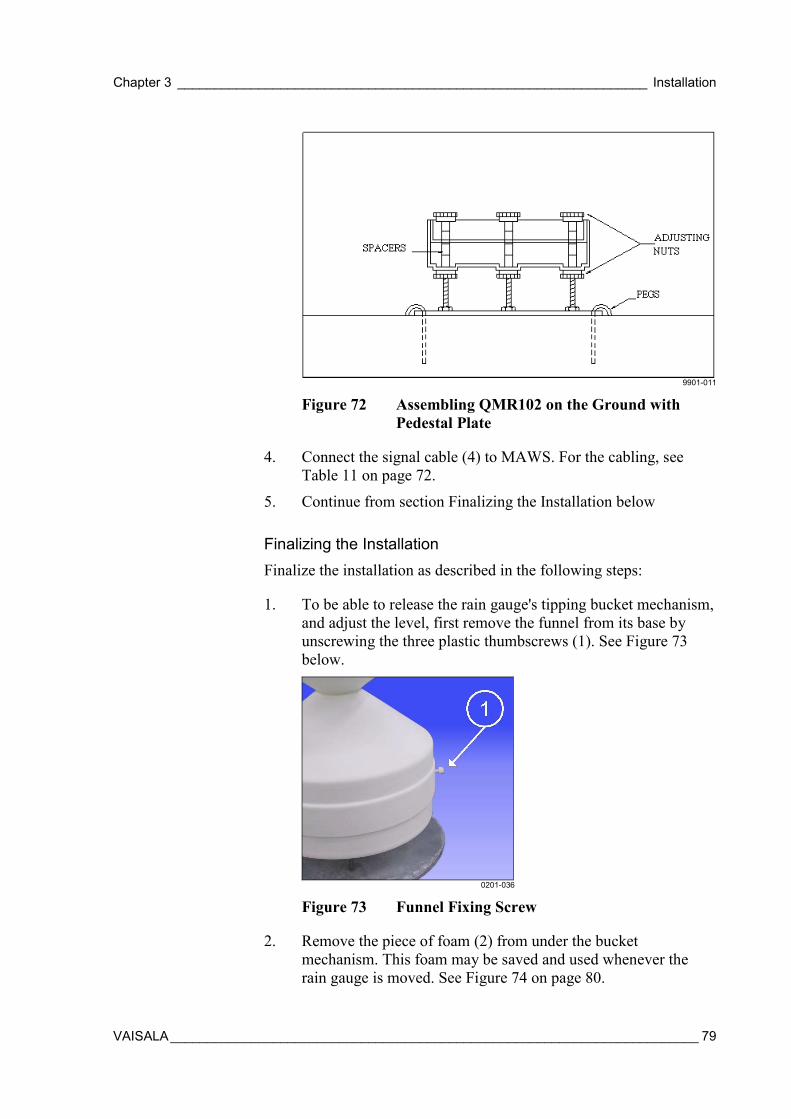
Chapter 3 ________________________________________________________________ Installation
VAISALA________________________________________________________________________ 79
9901-011
Figure 72 Assembling QMR102 on the Ground withPedestal Plate
4. Connect the signal cable (4) to MAWS. For the cabling, seeTable 11 on page 72.
5. Continue from section Finalizing the Installation below
Finalizing the InstallationFinalize the installation as described in the following steps:
1. To be able to release the rain gauge's tipping bucket mechanism,and adjust the level, first remove the funnel from its base byunscrewing the three plastic thumbscrews (1). See Figure 73below.
0201-036
Figure 73 Funnel Fixing Screw
2. Remove the piece of foam (2) from under the bucketmechanism. This foam may be saved and used whenever therain gauge is moved. See Figure 74 on page 80.
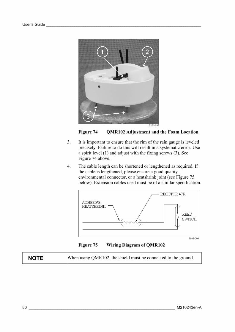
User's Guide _______________________________________________________________________
80 ___________________________________________________________________ M210243en-A
0201-037
Figure 74 QMR102 Adjustment and the Foam Location
3. It is important to ensure that the rim of the rain gauge is leveledprecisely. Failure to do this will result in a systematic error. Usea spirit level (1) and adjust with the fixing screws (3). SeeFigure 74 above.
4. The cable length can be shortened or lengthened as required. Ifthe cable is lengthened, please ensure a good qualityenvironmental connector, or a heatshrink joint (see Figure 75below). Extension cables used must be of a similar specification.
9902-004
Figure 75 Wiring Diagram of QMR102
NOTE When using QMR102, the shield must be connected to the ground.
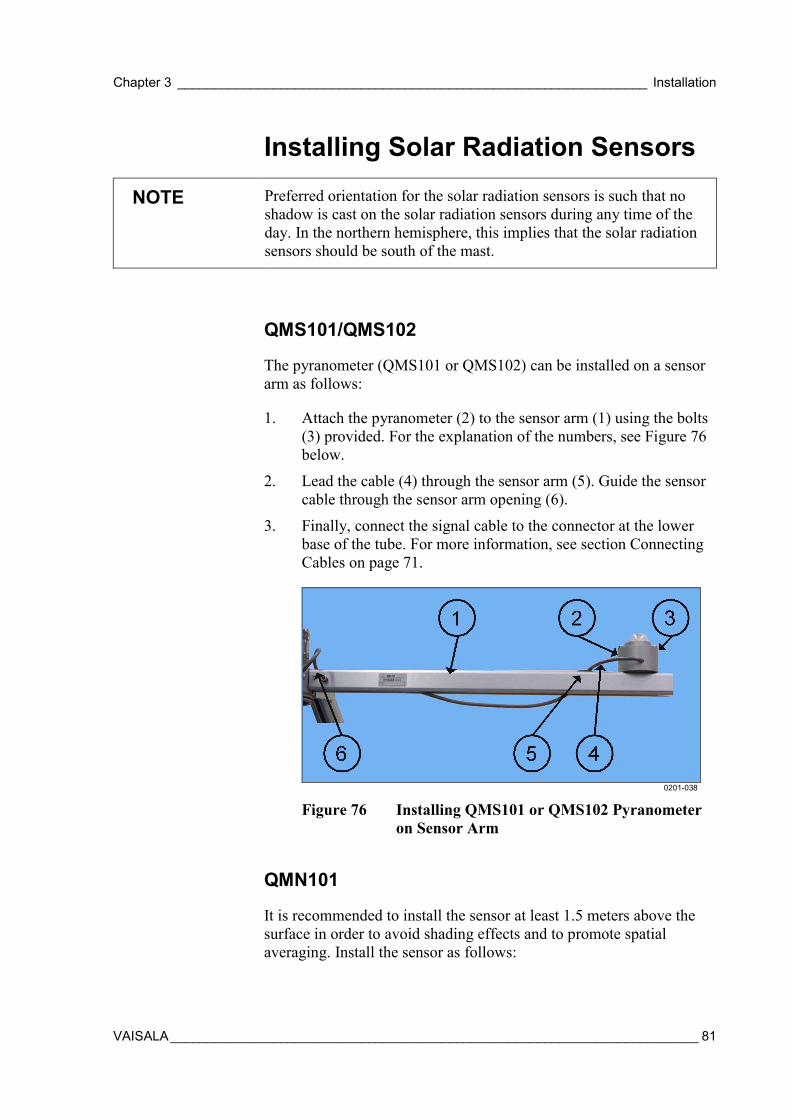
Chapter 3 ________________________________________________________________ Installation
VAISALA________________________________________________________________________ 81
Installing Solar Radiation Sensors
NOTE Preferred orientation for the solar radiation sensors is such that noshadow is cast on the solar radiation sensors during any time of theday. In the northern hemisphere, this implies that the solar radiationsensors should be south of the mast.
QMS101/QMS102
The pyranometer (QMS101 or QMS102) can be installed on a sensorarm as follows:
1. Attach the pyranometer (2) to the sensor arm (1) using the bolts(3) provided. For the explanation of the numbers, see Figure 76below.
2. Lead the cable (4) through the sensor arm (5). Guide the sensorcable through the sensor arm opening (6).
3. Finally, connect the signal cable to the connector at the lowerbase of the tube. For more information, see section ConnectingCables on page 71.
0201-038
Figure 76 Installing QMS101 or QMS102 Pyranometeron Sensor Arm
QMN101
It is recommended to install the sensor at least 1.5 meters above thesurface in order to avoid shading effects and to promote spatialaveraging. Install the sensor as follows:

User's Guide _______________________________________________________________________
82 ___________________________________________________________________ M210243en-A
1. Slide the mounting piece (1) to the sensor arm (2). Tighten withthe screws. For the numbers, see Figure 77 below.
2. Attach the radiometer (3) to the extension arm (4). Attach thesensor's extension arm (4) to the mounting piece (1). Tightenwith the screws.
3. Lead the cable (5) through the sensor arm (1). Guide the sensorcable through the sensor arm opening (6).
4. Finally, connect the signal cable to the connector at the lowerbase of the tube. For more information, see section ConnectingCables on page 71.
0201-039
Figure 77 Installing QMN101 Net Radiometer
Installing Soil TemperatureSensors
QMT103
QMT103 soil/water temperature sensor has a ready-made 5 m cableand the connector. The connector L at the lower base of the tube isreserved for the first sensor. The connectors M and O can also be usedfor additional soil/water temperature sensor. For more information,see Table 10 on page 71.
QMT107
During a typical installation, QMT107 probe is pressed into pre-formed holes, but they can also be placed into excavated holes that arethen filled. On hard or rocky ground, a pilot hole is pre-formed withan auger rod. Drill a hole according to the following procedure:
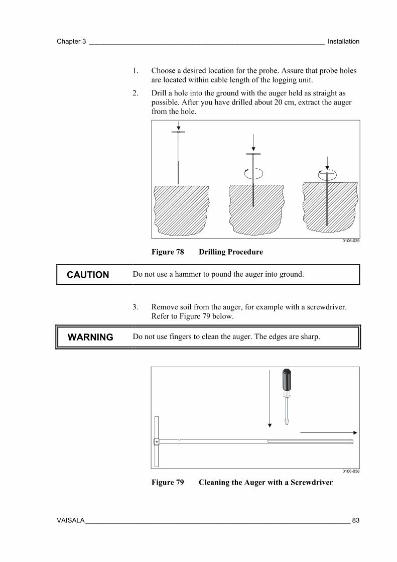
Chapter 3 ________________________________________________________________ Installation
VAISALA________________________________________________________________________ 83
1. Choose a desired location for the probe. Assure that probe holesare located within cable length of the logging unit.
2. Drill a hole into the ground with the auger held as straight aspossible. After you have drilled about 20 cm, extract the augerfrom the hole.
0106-039
Figure 78 Drilling Procedure
CAUTION Do not use a hammer to pound the auger into ground.
3. Remove soil from the auger, for example with a screwdriver.Refer to Figure 79 below.
WARNING Do not use fingers to clean the auger. The edges are sharp.
0106-038
Figure 79 Cleaning the Auger with a Screwdriver
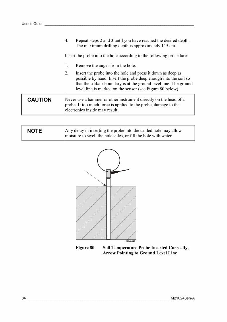
User's Guide _______________________________________________________________________
84 ___________________________________________________________________ M210243en-A
4. Repeat steps 2 and 3 until you have reached the desired depth.The maximum drilling depth is approximately 115 cm.
Insert the probe into the hole according to the following procedure:
1. Remove the auger from the hole.
2. Insert the probe into the hole and press it down as deep aspossible by hand. Insert the probe deep enough into the soil sothat the soil/air boundary is at the ground level line. The groundlevel line is marked on the sensor (see Figure 80 below).
CAUTION Never use a hammer or other instrument directly on the head of aprobe. If too much force is applied to the probe, damage to theelectronics inside may result.
NOTE Any delay in inserting the probe into the drilled hole may allowmoisture to swell the hole sides, or fill the hole with water.
0106-042
Figure 80 Soil Temperature Probe Inserted Correctly,Arrow Pointing to Ground Level Line

Chapter 3 ________________________________________________________________ Installation
VAISALA________________________________________________________________________ 85
CAUTION DO NOT drive or press probes directly into soil of unknowncomposition.
DO NOT bend or flex probes during insertion or extraction.
DO NOT attach unapproved electrical devices or test equipment tothe probe.
DO make a pilot hole prior to each probe insertion, unless the soilconsists of homogenous, loose sand.
DO inspect and clean the probe connector prior to each use.
Note that probe warranty is void if a hammer or unapproved tool isused to drive the probe into the soil.
3. Finally, connect the signal cable to the connector at the lowerbase of the tube. For more information, see section ConnectingCables on page 71.
Installing Soil Moisture SensorTo install the ML2x sensor, follow the procedure below:
1. The sensor can either be inserted or buried into the soil as shownin Figure 81 below and Figure 82 on page 86.
0105-087
Figure 81 ML2x Soil Moisture Sensor

User's Guide _______________________________________________________________________
86 ___________________________________________________________________ M210243en-A
0105-088
Figure 82 Buried ML2x Sensors
2. Pull the sensor cable close to the equipment enclosure. Cut thecable to a proper length. Thread the cable through the connectorparts in the indicated order 1-2-3-4. See Figure 56 on page 66.
3. Strip the sensor cable wires and connect them to connectorterminals according to Table 12 below. Make sure that thespring of lead-in connector is in good contact with the shield.Assemble the connector.
Table 12 Cable Pins of ML2x Soil Moisture SensorPin Number Wire Color Signal1 Red Supply, +2 Yellow Signal HI3 Blue Supply, -4 Green Signal LO
4. Finally, connect the signal cable to the connector at the lowerbase of the tube. For more information, see section ConnectingCables on page 71.
Installing Water Level Sensors
QMV101/QMV102
For the location of the QMV101/QMV102 water level sensor, seesection Water Level on page 51.
QMV sensors have a ready-made cable and a connector. Connect thesignal cable to an available connector at the bottom of the tube (seesection Connecting Cables on page 71).

Chapter 3 ________________________________________________________________ Installation
VAISALA________________________________________________________________________ 87
Installing Leaf Wetness SensorQLW101 Leaf Wetness Sensor is delivered with an installationhardware kit and a 5-meter long sensor cable.
You may test the sensor before you install it. The instructions belowprovide a description of the suggested quick test procedure.
1. Connect the signal cable to the connector at the lower base ofthe tube. For more information, see section Connecting Cableson page 71.
2. Configure the sensor. See the MAWS Lizard User's Guide forinstructions.
3. Drop or spray water onto the sensor and make sure the readingchanges.
On the Wooden Surface
To mount the sensor against a wooden surface, secure the sensor tothe surface using wood screws (see Figure 83 below).
0105-070
Figure 83 Mounting QLW101 to a Wooden Surface
To a Pole Mast
You can mount the sensor to a mast with an outside diameter between25 and 31 mm. Secure the sensor to the pipe using the U-bolt, flatwashers, and hex nuts as shown in Figure 84 on page 88. Use a rightsize wrench or adjustable wrench to tighten the hex nuts.
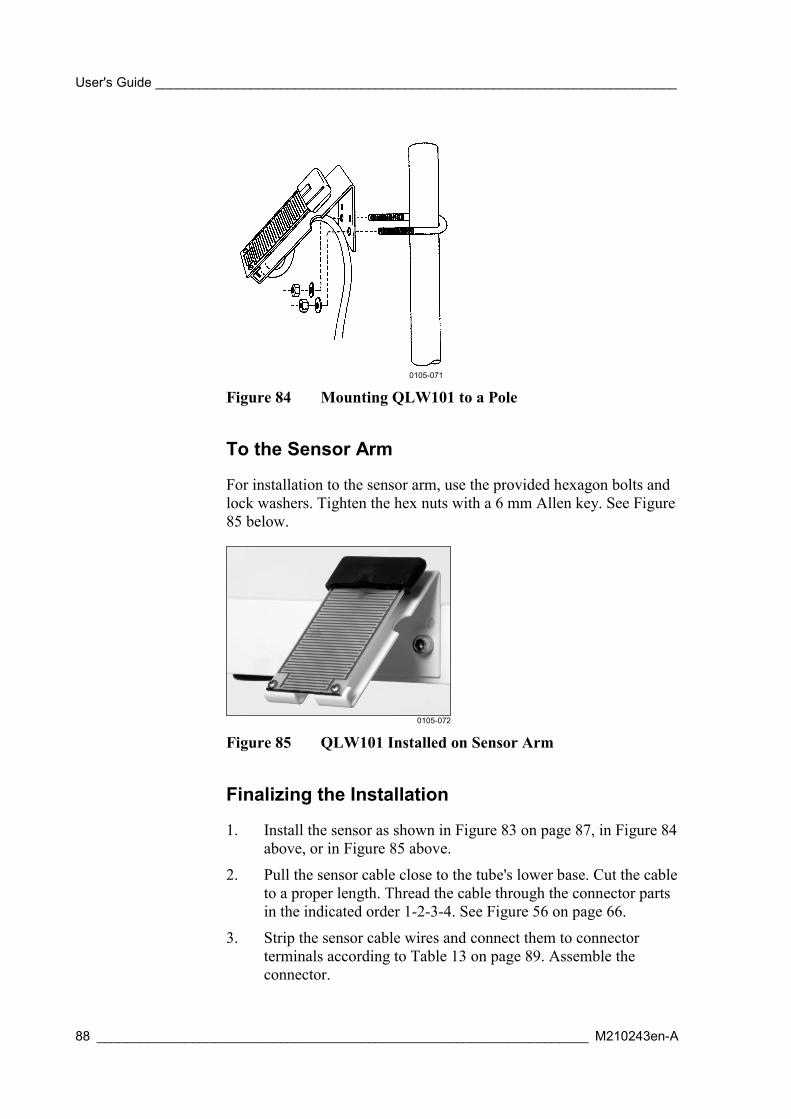
User's Guide _______________________________________________________________________
88 ___________________________________________________________________ M210243en-A
0105-071
Figure 84 Mounting QLW101 to a Pole
To the Sensor Arm
For installation to the sensor arm, use the provided hexagon bolts andlock washers. Tighten the hex nuts with a 6 mm Allen key. See Figure85 below.
0105-072
Figure 85 QLW101 Installed on Sensor Arm
Finalizing the Installation
1. Install the sensor as shown in Figure 83 on page 87, in Figure 84above, or in Figure 85 above.
2. Pull the sensor cable close to the tube's lower base. Cut the cableto a proper length. Thread the cable through the connector partsin the indicated order 1-2-3-4. See Figure 56 on page 66.
3. Strip the sensor cable wires and connect them to connectorterminals according to Table 13 on page 89. Assemble theconnector.

Chapter 3 ________________________________________________________________ Installation
VAISALA________________________________________________________________________ 89
Table 13 Cable Pins of QLW101 Leaf Wetness SensorPin Number Wire Color Signal1 Red Supply, +2 White Signal HI3 Black (two wires) Supply, -
4. Loosen and remove two hand screws beneath the tube. Slide thetube down to expose the logger (see Figure 34 on page 53).
5. Remove a connector from the input channel. Exact channeldepends on your configuration. Insert adapter QLA001 to thechannel and place the connector on top of it.
6. Connect the signal cable to an available connector at the bottomof the tube (see section Connecting Cables on page 71).
0201-040
Figure 86 Adapter Installed to Connector
Installing Fuel Moisture SensorYou should install the QFM101 sensor 30 cm above the forest floorand orient the sensor parallel to the ground.
CAUTION It is important to keep the wooden dowel part of the sensor clean.Avoid touching the dowel with bare hands. Any contact with greaseor oil will prevent the sensor from exchanging moisture and willmake the calibration invalid.
QFM101 uses two analog channels of the logger: one for thetemperature measurement and another for the moisture measurement.Moisture is measured via one of the channels CH1 to CH3. Youshould connect the sensor cable to the appropriate channel.Temperature is measured with one of the channels CH4 to CH7 andtherefore you should modify the wiring as instructed below.
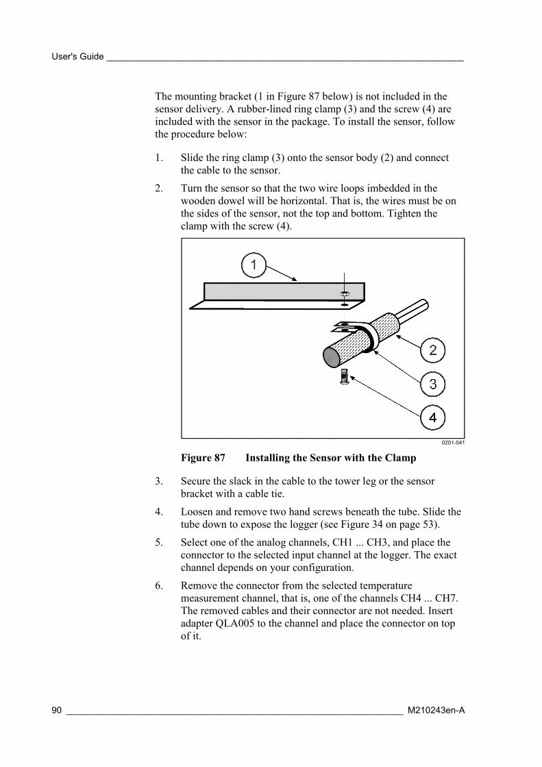
User's Guide _______________________________________________________________________
90 ___________________________________________________________________ M210243en-A
The mounting bracket (1 in Figure 87 below) is not included in thesensor delivery. A rubber-lined ring clamp (3) and the screw (4) areincluded with the sensor in the package. To install the sensor, followthe procedure below:
1. Slide the ring clamp (3) onto the sensor body (2) and connectthe cable to the sensor.
2. Turn the sensor so that the two wire loops imbedded in thewooden dowel will be horizontal. That is, the wires must be onthe sides of the sensor, not the top and bottom. Tighten theclamp with the screw (4).
0201-041
Figure 87 Installing the Sensor with the Clamp
3. Secure the slack in the cable to the tower leg or the sensorbracket with a cable tie.
4. Loosen and remove two hand screws beneath the tube. Slide thetube down to expose the logger (see Figure 34 on page 53).
5. Select one of the analog channels, CH1 ... CH3, and place theconnector to the selected input channel at the logger. The exactchannel depends on your configuration.
6. Remove the connector from the selected temperaturemeasurement channel, that is, one of the channels CH4 ... CH7.The removed cables and their connector are not needed. Insertadapter QLA005 to the channel and place the connector on topof it.

Chapter 3 ________________________________________________________________ Installation
VAISALA________________________________________________________________________ 91
0201-040
Figure 88 Adapter Installed to Connector
7. Modify the wiring according to the Table 14 below.
Table 14 Modified Wiring with QFM101WireColor
Standard ConnectionPin at the Logger
Modified Connection Pin at theLogger
Red Not connected. Connect the wire to theterminal C of the selectedtemperature measurementchannel (CH4 ... CH7).
Brown E Leave as is. This wire is used forthe moisture measurement.
White H Leave as is. This wire is used forthe moisture measurement.
Black L Move the wire to the terminal Eof the selected temperaturechannel (CH4 ... CH7).
Blue C Leave as is. This wire is used forthe moisture measurement.
8. Connect the signal cable to the connector of the modified inputchannel at the bottom of the tube (see section Connecting Cableson page 71).
Installing Communication Devices
Installing Communication ModulesModules can be attached on the circuit board to providecommunication channels for MAWS. For the placement of themodules, see Figure 89 on page 92. The modules can simply bepushed on the connector blocks MOD1 and/or MOD2. Moduleoptions include DSU232, DSI485A, DSI486, and DMX501. Bydefault, the modules are installed as described in Table 15 on page 92.

User's Guide _______________________________________________________________________
92 ___________________________________________________________________ M210243en-A
Table 15 Default Configuration for Communication ModulesModule Connector Block PortDSU232 MOD1 COM1DSI485A / DSI486 MOD2 COM2DMX501 MOD2 COM2
CAUTION When inserting, be careful not to bend the connector pins.
MOD1
MOD2
0105-055
Figure 89 Module Placement
For the principal wiring diagrams of the modules, see section WiringDiagrams on page 163.
Installing SATELLINE 3AS RadioModemThe radio modem SATELLINE 3AS comes with a ready-made cable(approx. 0.5 m) and a special weatherproof enclosure.
The DSU232 communication module should be used to provide anadditional RS232 output for the radio modem, leaving the standardCOM port (COM0) free for maintenance purposes.
For powering of the radio modem, you need a mains power supply ora mains/solar power supply with backup batteries. The standard solarpanel can not supply sufficient power for the radio modem. In
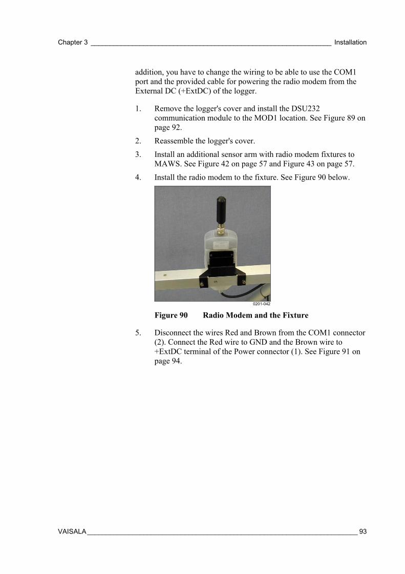
Chapter 3 ________________________________________________________________ Installation
VAISALA________________________________________________________________________ 93
addition, you have to change the wiring to be able to use the COM1port and the provided cable for powering the radio modem from theExternal DC (+ExtDC) of the logger.
1. Remove the logger's cover and install the DSU232communication module to the MOD1 location. See Figure 89 onpage 92.
2. Reassemble the logger's cover.
3. Install an additional sensor arm with radio modem fixtures toMAWS. See Figure 42 on page 57 and Figure 43 on page 57.
4. Install the radio modem to the fixture. See Figure 90 below.
0201-042
Figure 90 Radio Modem and the Fixture
5. Disconnect the wires Red and Brown from the COM1 connector(2). Connect the Red wire to GND and the Brown wire to+ExtDC terminal of the Power connector (1). See Figure 91 onpage 94.

User's Guide _______________________________________________________________________
94 ___________________________________________________________________ M210243en-A
0201-043
Figure 91 Wire Modifications with Radio Modem
6. Connect the ready-made radio modem's cable to the port COM1in the lower base of the tube.
NOTE It is recommended to label these modifications so that no otherequipment is connected to COM1 by mistake. The 12 VDC voltagemay damage some equipment.
7. Configure the radio modem with MAWS Lizard. For detailedinformation, refer to Technical Reference listed in Table 2 onpage 15.
Installing Accessories
External Memory Expansion Board1. Open the screw on the logger's cover and remove the cover.
2. Remove the communication modules (if any) from the circuitboard.
CAUTION Be careful not to bend the connector pins.
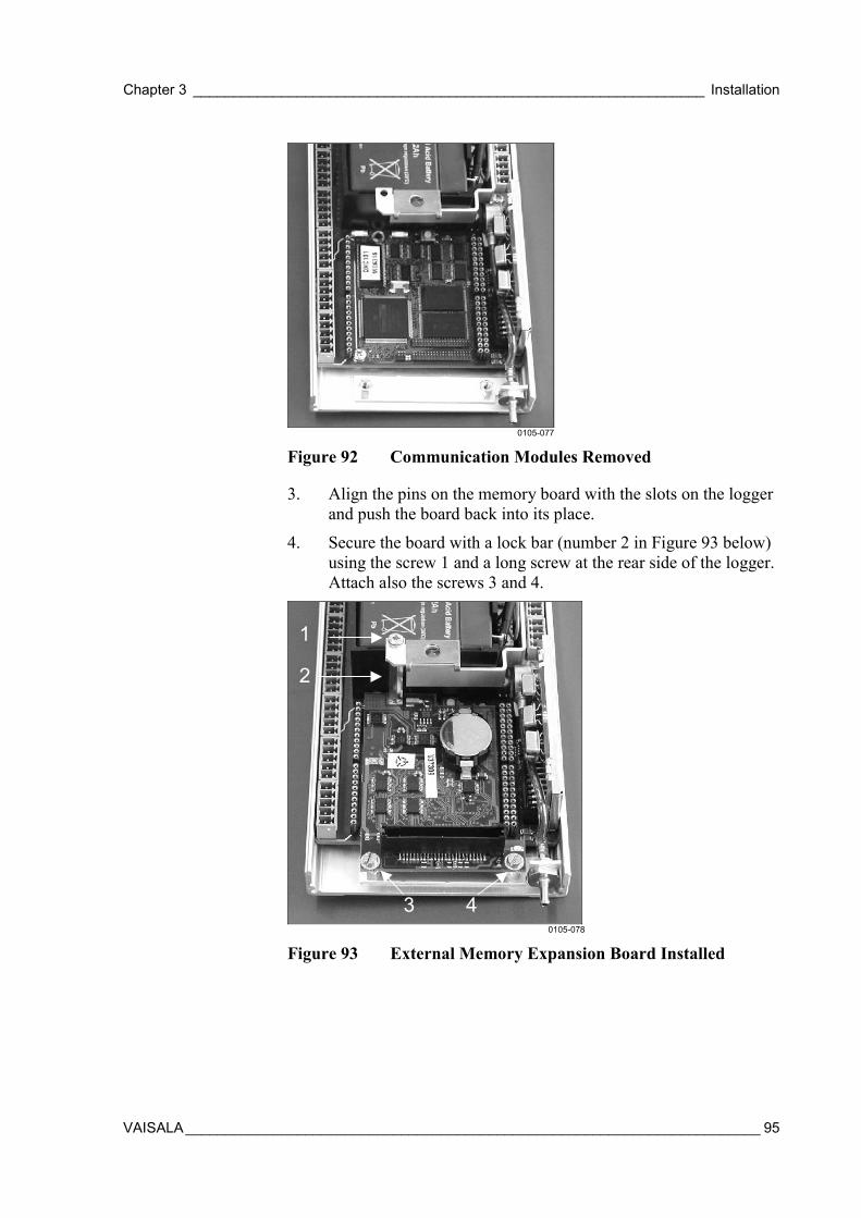
Chapter 3 ________________________________________________________________ Installation
VAISALA________________________________________________________________________ 95
0105-077
Figure 92 Communication Modules Removed
3. Align the pins on the memory board with the slots on the loggerand push the board back into its place.
4. Secure the board with a lock bar (number 2 in Figure 93 below)using the screw 1 and a long screw at the rear side of the logger.Attach also the screws 3 and 4.
1
2
3 40105-078
Figure 93 External Memory Expansion Board Installed

User's Guide _______________________________________________________________________
96 ___________________________________________________________________ M210243en-A
Installing Software
Installing Embedded SoftwareThe embedded software on the logger is normally installed at thefactory. For the instructions on installing a new, updated version, seethe Software Loading Technical Notice listed in Table 2 on page 15.
Installing MAWS TerminalFor the instructions on installing the MAWS Terminal software to aPC, see the MAWS Lizard User's Guide listed in Table 2 on page 15.
Installing LizardFor the instructions on installing the MAWS Lizard setup software toa PC, see the User's Guide listed in Table 2 on page 15.

Chapter 3 ________________________________________________________________ Installation
VAISALA________________________________________________________________________ 97
Disassembly of MAWS201 for Transportation1. Disconnect the power as follows:
a. For short storage periods, set the MAWS into low powerconsumption mode by giving the command SLEEP.
b. For long periods (over one month), disconnect the battery.First, open the hand screws that hold the tube in its place.Open logger housing. Detach red wire from the + terminal.Attach logger housing, lift the tube up and secure it withthe hand screws.
2. Remove the cables from the upper and lower base connectors.
3. Detach sensor arm(s). Insert the screws back in their places forsafekeeping.
4. Detach upper tube. Insert the screw back in its place forsafekeeping.
5. Remove wind sensor by opening the plastic collar. Detach windcable.
6. Tilt the solar panel so that it is parallel to the tripod leg. Coverthe panel by an opaque cover or other material before electricalconnections to the modules or other system components arehandled.
7. Loosen the Locking screw, put the legs together and tighten thelocking screw again.
WARNING Be careful when drawing together the tripod legs. See that there areno power lines or other obstacles above the mast (and wind sensor).
QMT107 Probe ExtractionFollow the procedure below to extract the probe. See Figure 94 onpage 98):
1. Set a piece of wood or similar close to the sensor.
2. Pass the auger rod through the wire loop at the top of the probe.
3. Make the auger handle rest onto the piece of wood.
4. Lift the probe.
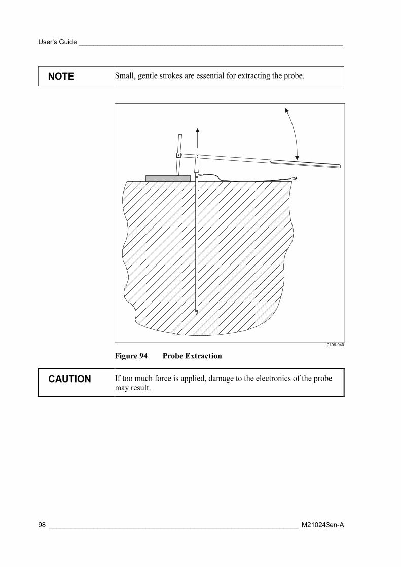
User's Guide _______________________________________________________________________
98 ___________________________________________________________________ M210243en-A
NOTE Small, gentle strokes are essential for extracting the probe.
0106-040
Figure 94 Probe Extraction
CAUTION If too much force is applied, damage to the electronics of the probemay result.
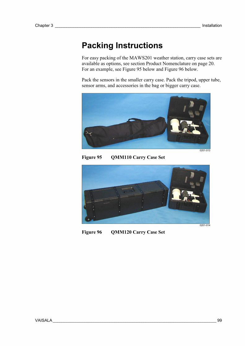
Chapter 3 ________________________________________________________________ Installation
VAISALA________________________________________________________________________ 99
Packing InstructionsFor easy packing of the MAWS201 weather station, carry case sets areavailable as options, see section Product Nomenclature on page 20.For an example, see Figure 95 below and Figure 96 below.
Pack the sensors in the smaller carry case. Pack the tripod, upper tube,sensor arms, and accessories in the bag or bigger carry case.
0201-013
Figure 95 QMM110 Carry Case Set
0201-014
Figure 96 QMM120 Carry Case Set

User's Guide _______________________________________________________________________
100 __________________________________________________________________ M210243en-A
This page intentionally left blank.
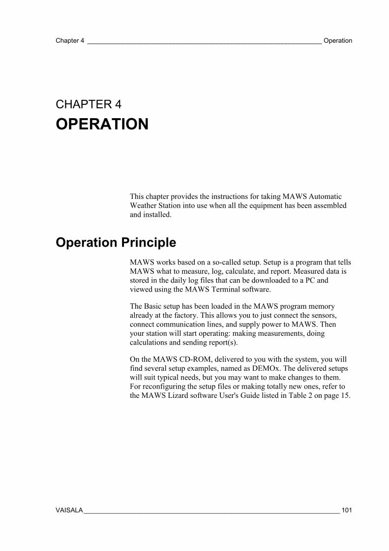
Chapter 4 _________________________________________________________________ Operation
VAISALA_______________________________________________________________________ 101
CHAPTER 4
OPERATION
This chapter provides the instructions for taking MAWS AutomaticWeather Station into use when all the equipment has been assembledand installed.
Operation PrincipleMAWS works based on a so-called setup. Setup is a program that tellsMAWS what to measure, log, calculate, and report. Measured data isstored in the daily log files that can be downloaded to a PC andviewed using the MAWS Terminal software.
The Basic setup has been loaded in the MAWS program memoryalready at the factory. This allows you to just connect the sensors,connect communication lines, and supply power to MAWS. Thenyour station will start operating: making measurements, doingcalculations and sending report(s).
On the MAWS CD-ROM, delivered to you with the system, you willfind several setup examples, named as DEMOx. The delivered setupswill suit typical needs, but you may want to make changes to them.For reconfiguring the setup files or making totally new ones, refer tothe MAWS Lizard software User's Guide listed in Table 2 on page 15.
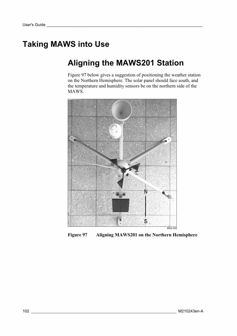
User's Guide _______________________________________________________________________
102 __________________________________________________________________ M210243en-A
Taking MAWS into Use
Aligning the MAWS201 StationFigure 97 below gives a suggestion of positioning the weather stationon the Northern Hemisphere. The solar panel should face south, andthe temperature and humidity sensors be on the northern side of theMAWS.
9902-002
Figure 97 Aligning MAWS201 on the Northern Hemisphere
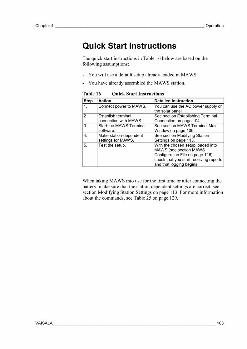
Chapter 4 _________________________________________________________________ Operation
VAISALA_______________________________________________________________________ 103
Quick Start InstructionsThe quick start instructions in Table 16 below are based on thefollowing assumptions:
- You will use a default setup already loaded in MAWS.
- You have already assembled the MAWS station.
Table 16 Quick Start InstructionsStep Action Detailed Instruction1. Connect power to MAWS. You can use the AC power supply or
the solar panel.2. Establish terminal
connection with MAWS.See section Establishing TerminalConnection on page 104.
3. Start the MAWS Terminalsoftware.
See section MAWS Terminal MainWindow on page 106.
4. Make station-dependentsettings for MAWS.
See section Modifying StationSettings on page 113.
5. Test the setup. With the chosen setup loaded intoMAWS (see section MAWSConfiguration File on page 116),check that you start receiving reportsand that logging begins.
When taking MAWS into use for the first time or after connecting thebattery, make sure that the station dependent settings are correct, seesection Modifying Station Settings on page 113. For more informationabout the commands, see Table 25 on page 129.

User's Guide _______________________________________________________________________
104 __________________________________________________________________ M210243en-A
Establishing Terminal ConnectionTo connect your computer to a MAWS serial port, proceed as follows:
1. Connect the provided terminal cable (QMZ101) to the COM0connector in the bottom plate of the tube and to an availableCOM port on your PC. See Figure 98 below.
0201-044
Figure 98 Connecting the Terminal Cable
2. Start MAWS Terminal program on your PC, as instructed insection Using MAWS Terminal Software on page 105.
3. Set communication parameters: 9600, N, 8, 1.For moreinformation, see section Opening MAWS Service Connectionon page 110.
4. Give the command open (if the connection is not already open).For more information, see section Giving Commands on page112.
NOTE The command open is not echoed on the screen.
Figure 99 on page 105 shows the pin order for the terminal connector.

Chapter 4 _________________________________________________________________ Operation
VAISALA_______________________________________________________________________ 105
0201-045
Figure 99 COM0 Pins for the Terminal Connector
Using MAWS Terminal Software
Selecting the LanguageWhen you start MAWS Terminal for the first time, you will be askedto select the language you would like to use. The Select Languagewindow, presented in Figure 100 below, will appear. Select thedesired language and click OK.
Figure 100 Select Language Window
The Select Language window will only appear when MAWSTerminal is started for the first time. To change the language later,choose Preferences from the Settings menu, and then select theLanguage tab. In the Language tab, select the desired language fromthe Available Languages box and click OK.
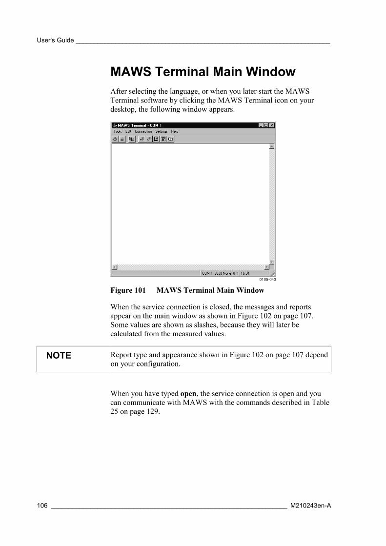
User's Guide _______________________________________________________________________
106 __________________________________________________________________ M210243en-A
MAWS Terminal Main WindowAfter selecting the language, or when you later start the MAWSTerminal software by clicking the MAWS Terminal icon on yourdesktop, the following window appears.
0105-040
Figure 101 MAWS Terminal Main Window
When the service connection is closed, the messages and reportsappear on the main window as shown in Figure 102 on page 107.Some values are shown as slashes, because they will later becalculated from the measured values.
NOTE Report type and appearance shown in Figure 102 on page 107 dependon your configuration.
When you have typed open, the service connection is open and youcan communicate with MAWS with the commands described in Table25 on page 129.
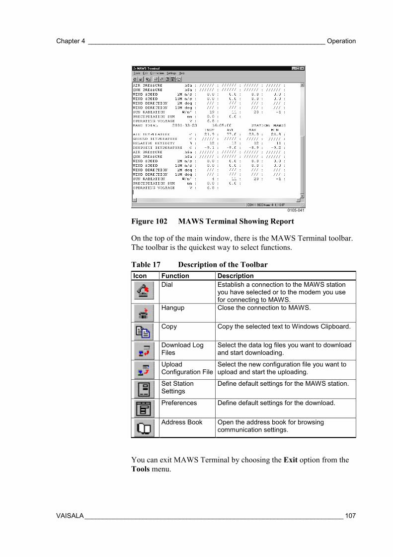
Chapter 4 _________________________________________________________________ Operation
VAISALA_______________________________________________________________________ 107
0105-041
Figure 102 MAWS Terminal Showing Report
On the top of the main window, there is the MAWS Terminal toolbar.The toolbar is the quickest way to select functions.
Table 17 Description of the ToolbarIcon Function Description
Dial Establish a connection to the MAWS stationyou have selected or to the modem you usefor connecting to MAWS.
Hangup Close the connection to MAWS.
Copy Copy the selected text to Windows Clipboard.
Download LogFiles
Select the data log files you want to downloadand start downloading.
UploadConfiguration File
Select the new configuration file you want toupload and start the uploading.
Set StationSettings
Define default settings for the MAWS station.
Preferences Define default settings for the download.
Address Book Open the address book for browsingcommunication settings.
You can exit MAWS Terminal by choosing the Exit option from theTools menu.
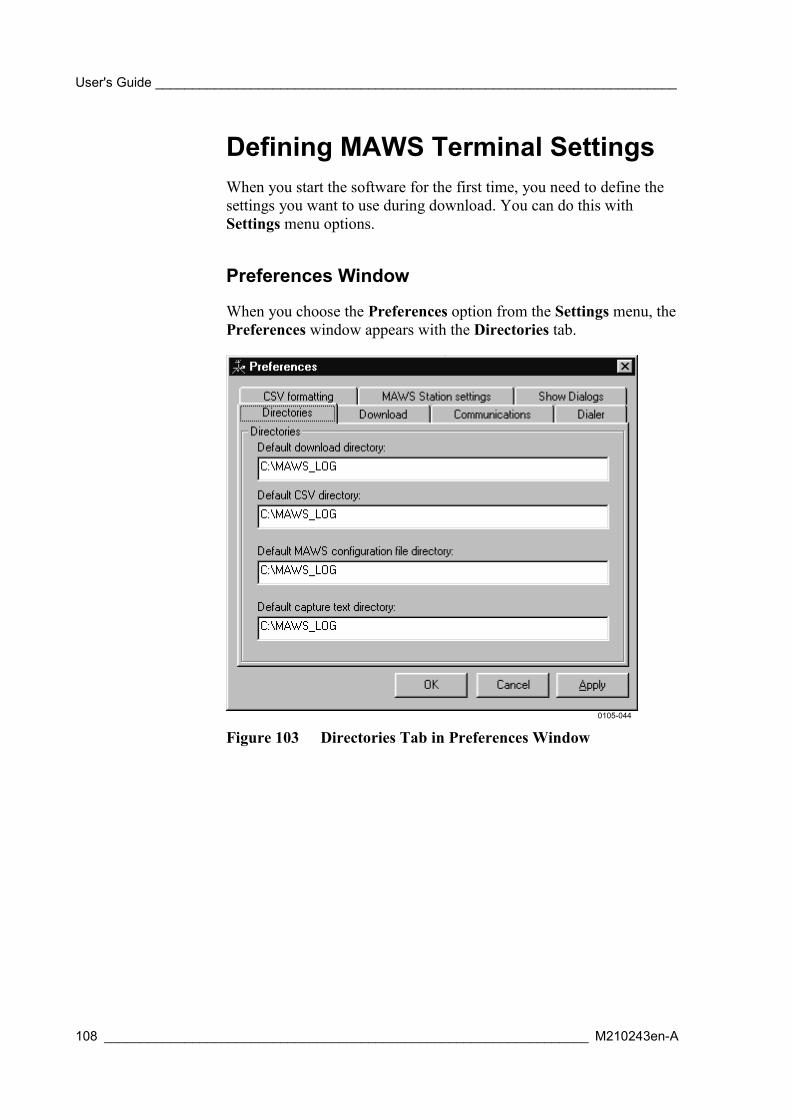
User's Guide _______________________________________________________________________
108 __________________________________________________________________ M210243en-A
Defining MAWS Terminal SettingsWhen you start the software for the first time, you need to define thesettings you want to use during download. You can do this withSettings menu options.
Preferences Window
When you choose the Preferences option from the Settings menu, thePreferences window appears with the Directories tab.
0105-044
Figure 103 Directories Tab in Preferences Window
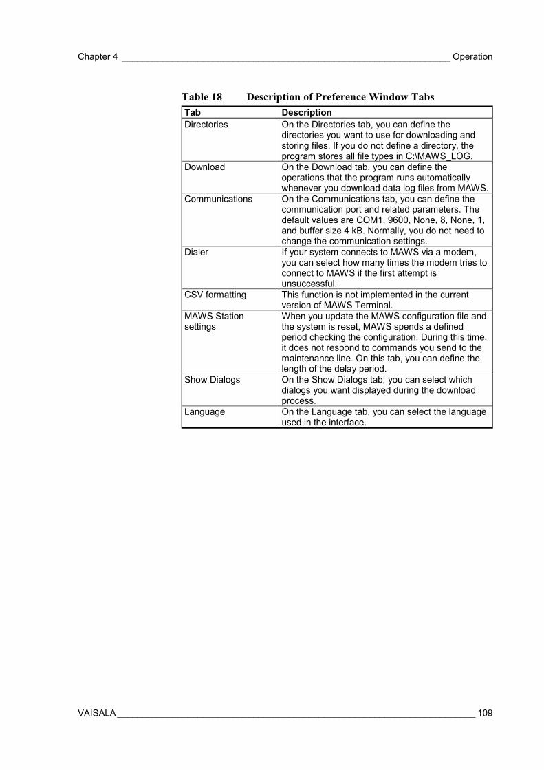
Chapter 4 _________________________________________________________________ Operation
VAISALA_______________________________________________________________________ 109
Table 18 Description of Preference Window TabsTab DescriptionDirectories On the Directories tab, you can define the
directories you want to use for downloading andstoring files. If you do not define a directory, theprogram stores all file types in C:\MAWS_LOG.
Download On the Download tab, you can define theoperations that the program runs automaticallywhenever you download data log files from MAWS.
Communications On the Communications tab, you can define thecommunication port and related parameters. Thedefault values are COM1, 9600, None, 8, None, 1,and buffer size 4 kB. Normally, you do not need tochange the communication settings.
Dialer If your system connects to MAWS via a modem,you can select how many times the modem tries toconnect to MAWS if the first attempt isunsuccessful.
CSV formatting This function is not implemented in the currentversion of MAWS Terminal.
MAWS Stationsettings
When you update the MAWS configuration file andthe system is reset, MAWS spends a definedperiod checking the configuration. During this time,it does not respond to commands you send to themaintenance line. On this tab, you can define thelength of the delay period.
Show Dialogs On the Show Dialogs tab, you can select whichdialogs you want displayed during the downloadprocess.
Language On the Language tab, you can select the languageused in the interface.
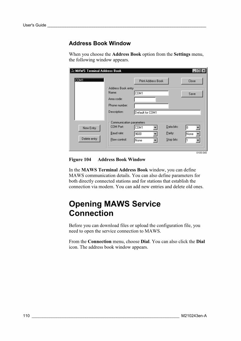
User's Guide _______________________________________________________________________
110 __________________________________________________________________ M210243en-A
Address Book Window
When you choose the Address Book option from the Settings menu,the following window appears.
0105-045
Figure 104 Address Book Window
In the MAWS Terminal Address Book window, you can defineMAWS communication details. You can also define parameters forboth directly connected stations and for stations that establish theconnection via modem. You can add new entries and delete old ones.
Opening MAWS ServiceConnectionBefore you can download files or upload the configuration file, youneed to open the service connection to MAWS.
From the Connection menu, choose Dial. You can also click the Dialicon. The address book window appears.
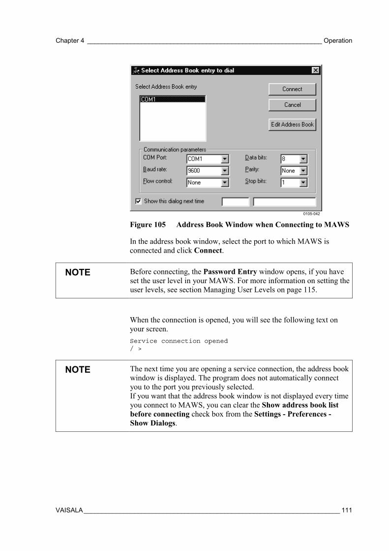
Chapter 4 _________________________________________________________________ Operation
VAISALA_______________________________________________________________________ 111
0105-042
Figure 105 Address Book Window when Connecting to MAWS
In the address book window, select the port to which MAWS isconnected and click Connect.
NOTE Before connecting, the Password Entry window opens, if you haveset the user level in your MAWS. For more information on setting theuser levels, see section Managing User Levels on page 115.
When the connection is opened, you will see the following text onyour screen.Service connection opened/ >
NOTE The next time you are opening a service connection, the address bookwindow is displayed. The program does not automatically connectyou to the port you previously selected.If you want that the address book window is not displayed every timeyou connect to MAWS, you can clear the Show address book listbefore connecting check box from the Settings - Preferences -Show Dialogs.
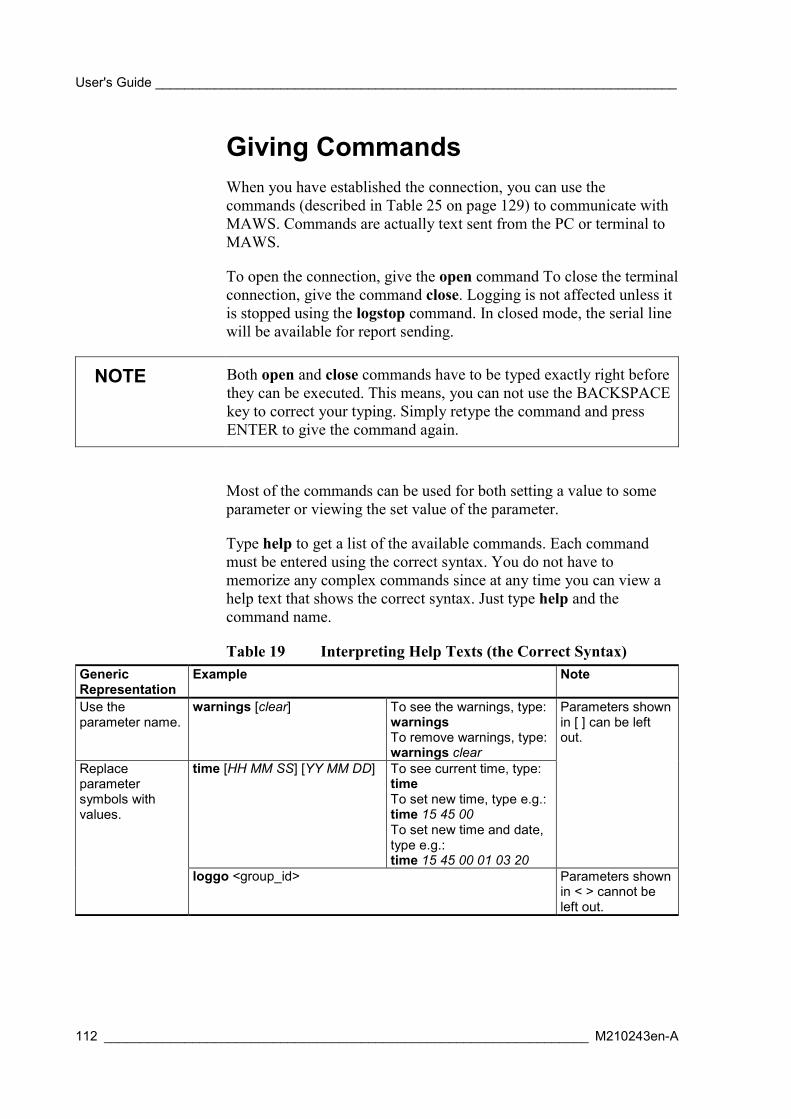
User's Guide _______________________________________________________________________
112 __________________________________________________________________ M210243en-A
Giving CommandsWhen you have established the connection, you can use thecommands (described in Table 25 on page 129) to communicate withMAWS. Commands are actually text sent from the PC or terminal toMAWS.
To open the connection, give the open command To close the terminalconnection, give the command close. Logging is not affected unless itis stopped using the logstop command. In closed mode, the serial linewill be available for report sending.
NOTE Both open and close commands have to be typed exactly right beforethey can be executed. This means, you can not use the BACKSPACEkey to correct your typing. Simply retype the command and pressENTER to give the command again.
Most of the commands can be used for both setting a value to someparameter or viewing the set value of the parameter.
Type help to get a list of the available commands. Each commandmust be entered using the correct syntax. You do not have tomemorize any complex commands since at any time you can view ahelp text that shows the correct syntax. Just type help and thecommand name.
Table 19 Interpreting Help Texts (the Correct Syntax)GenericRepresentation
Example Note
Use theparameter name.
warnings [clear] To see the warnings, type:warningsTo remove warnings, type:warnings clear
time [HH MM SS] [YY MM DD] To see current time, type:timeTo set new time, type e.g.:time 15 45 00To set new time and date,type e.g.:time 15 45 00 01 03 20
Parameters shownin [ ] can be leftout.
Replaceparametersymbols withvalues.
loggo <group_id> Parameters shownin < > cannot beleft out.

Chapter 4 _________________________________________________________________ Operation
VAISALA_______________________________________________________________________ 113
NOTE Commands have to be typed in the same case as indicated in the helptexts, usually in the lower case.
The command name and the following parameters are alwaysseparated by a space. Pressing ENTER (return) will execute thecommand so that MAWS reads the typed command.
You can use BACKSPACE to delete the last typed character.
Use CTRL+P (hold down the CTRL key and press P) to repeat thepreviously typed command. Use CTRL+P (Previous) and CTRL+N(Next) to scroll through the list of previously typed commands. Whenyou find the command you would like to repeat, simply press ENTER.File commands (dir, del, copy, move, verify) can be aborted withCTRL+C.
Closing MAWS Service ConnectionIf your MAWS connection works via a modem, you must rememberto close the line after you finish working with MAWS. To close theconnection, choose Hangup from the Connection menu.
If your MAWS connection is direct, you do not need to close theservice connection separately. The program closes the serviceconnection automatically after 5 minutes.
Modifying Station SettingsIn MAWS Terminal, you can modify the station settings. When youchoose the Set Stations Settings option from the Tools menu, thewindow appears. See Figure 106 on page 114. The separate boxes inthe left side of the window are for setting the common parameters to astation. The MAWS static parameters list shows the additionalparameters, also those that have been set directly with the MAWSTerminal software.
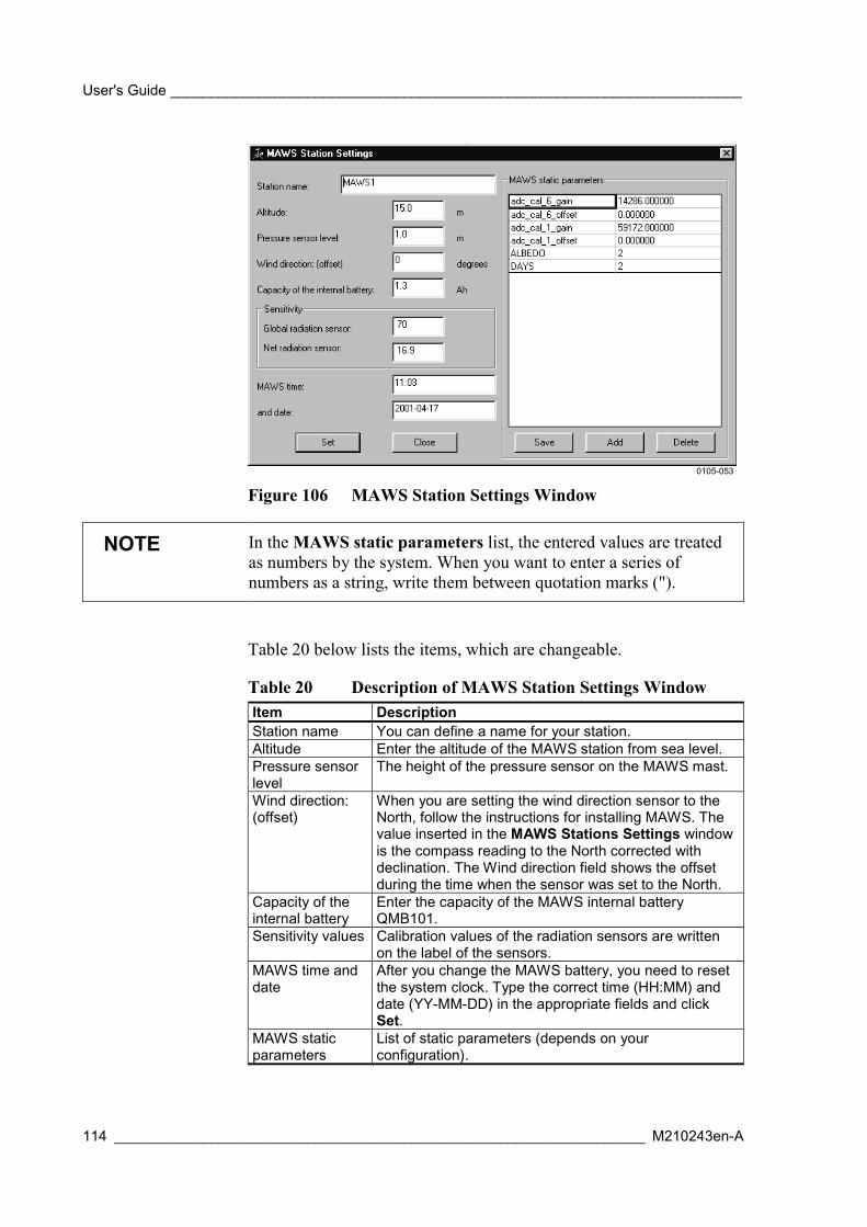
User's Guide _______________________________________________________________________
114 __________________________________________________________________ M210243en-A
0105-053
Figure 106 MAWS Station Settings Window
NOTE In the MAWS static parameters list, the entered values are treatedas numbers by the system. When you want to enter a series ofnumbers as a string, write them between quotation marks (").
Table 20 below lists the items, which are changeable.
Table 20 Description of MAWS Station Settings WindowItem DescriptionStation name You can define a name for your station.Altitude Enter the altitude of the MAWS station from sea level.Pressure sensorlevel
The height of the pressure sensor on the MAWS mast.
Wind direction:(offset)
When you are setting the wind direction sensor to theNorth, follow the instructions for installing MAWS. Thevalue inserted in the MAWS Stations Settings windowis the compass reading to the North corrected withdeclination. The Wind direction field shows the offsetduring the time when the sensor was set to the North.
Capacity of theinternal battery
Enter the capacity of the MAWS internal batteryQMB101.
Sensitivity values Calibration values of the radiation sensors are writtenon the label of the sensors.
MAWS time anddate
After you change the MAWS battery, you need to resetthe system clock. Type the correct time (HH:MM) anddate (YY-MM-DD) in the appropriate fields and clickSet.
MAWS staticparameters
List of static parameters (depends on yourconfiguration).
Chapter 4 _________________________________________________________________ Operation
VAISALA_______________________________________________________________________ 115
Managing User LevelsYou can use the userlevel command to protect the system fromunauthorized use. The system provides three password protectedaccess levels to the shell commands as well as to the visibility ofsystem data. By default, the user levels are not in use.
You can manage user levels by the userlevel command when theservice connection is open. The command has the following syntax:
userlevel [level <set/clear>]
where
level = 1, 3, or 5set = Sets the password for a levelclear = Clears the password from the level
To check the current setting, give the command alone, withoutparameters. When you want to change the level, give the commandwith parameters. When you change the level to a higher one, apassword is required. When you change the level to a lower one, apassword is not required.
To change the password for the level, give the command with theappropriate level and the set parameter. For this operation, theeffective user level has to be the highest, that is, 5. The change of thepassword becomes effective immediately.
To remove the password for the level, give the command with theappropriate level and the clear parameter. For this operation, theeffective user level has to be the highest, that is 5. The change of thepassword becomes effective immediately.
CAUTION Setting a new or clearing an existing user level is effective only afterresetting MAWS. When setting a new or clearing an existing level,be sure to reset the system before closing the service connection.Otherwise, you may not be able to access the system without the coldreset.
To check the allowed commands at the specific level, give the helpcommand. Table 21 on page 116 lists the accessible commands in thedifferent user levels. Level 1 provides access to minimum set ofcommands and visibility of system parameters. Level 3 provides
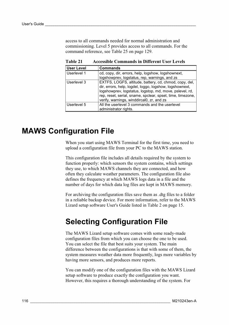
User's Guide _______________________________________________________________________
116 __________________________________________________________________ M210243en-A
access to all commands needed for normal administration andcommissioning. Level 5 provides access to all commands. For thecommand reference, see Table 25 on page 129.
Table 21 Accessible Commands in Different User LevelsUser Level CommandsUserlevel 1 cd, copy, dir, errors, help, logshow, logshownext,
logshowprev, logstatus, rep, warnings, and zsUserlevel 3 EXTFS, LOGFS, altitude, battery, cd, chmod, copy, del,
dir, errors, help, logdel, loggo, logshow, logshownext,logshowprev, logstatus, logstop, md, move, pslevel, rd,rep, reset, serial, sname, spclear, spset, time, timezone,verify, warnings, winddircal0, zr, and zs
Userlevel 5 All the userlevel 3 commands and the userleveladministrator rights.
MAWS Configuration FileWhen you start using MAWS Terminal for the first time, you need toupload a configuration file from your PC to the MAWS station.
This configuration file includes all details required by the system tofunction properly: which sensors the system contains, which settingsthey use, to which MAWS channels they are connected, and howoften they calculate weather parameters. The configuration file alsodefines the frequency at which MAWS logs data in a file and thenumber of days for which data log files are kept in MAWS memory.
For archiving the configuration files save them as .dtg files to a folderin a reliable backup device. For more information, refer to the MAWSLizard setup software User's Guide listed in Table 2 on page 15.
Selecting Configuration FileThe MAWS Lizard setup software comes with some ready-madeconfiguration files from which you can choose the one to be used.You can select the file that best suits your system. The maindifference between the configurations is that with some of them, thesystem measures weather data more frequently, logs more variables byhaving more sensors, and produces more reports.
You can modify one of the configuration files with the MAWS Lizardsetup software to produce exactly the configuration you want.However, this requires a thorough understanding of the system. For
Chapter 4 _________________________________________________________________ Operation
VAISALA_______________________________________________________________________ 117
more information, refer to the MAWS Lizard setup software User'sGuide listed in Table 2 on page 15.
CAUTION If you create a configuration of your own by modifying the ready-made files, store the new file under a different name. This way, youcan go back to the original configuration in case the new one is notworking.
Also notice that the settings you define in the configuration file mustmatch the settings you make in the Preferences window and theMAWS Stations Settings window.
Uploading Configuration FileYou need to upload the MAWS configuration file in two occasions:
- When you start using MAWS for the first time.
- When your system has been updated (for example, new sensorshave been added).
When you have opened the MAWS service connection, you can startuploading the configuration file. On the Tools menu, select UploadConfiguration.
The following window appears. Select the appropriate configurationfile and click Open.
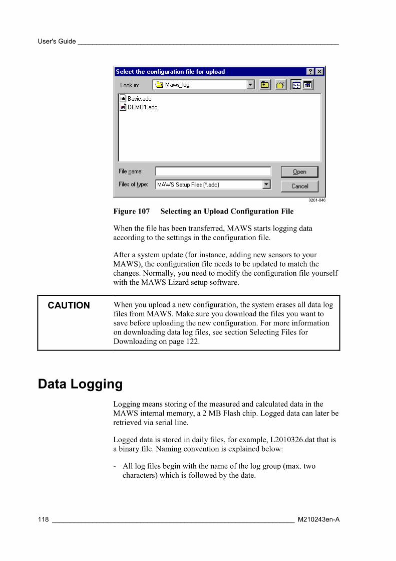
User's Guide _______________________________________________________________________
118 __________________________________________________________________ M210243en-A
0201-046
Figure 107 Selecting an Upload Configuration File
When the file has been transferred, MAWS starts logging dataaccording to the settings in the configuration file.
After a system update (for instance, adding new sensors to yourMAWS), the configuration file needs to be updated to match thechanges. Normally, you need to modify the configuration file yourselfwith the MAWS Lizard setup software.
CAUTION When you upload a new configuration, the system erases all data logfiles from MAWS. Make sure you download the files you want tosave before uploading the new configuration. For more informationon downloading data log files, see section Selecting Files forDownloading on page 122.
Data LoggingLogging means storing of the measured and calculated data in theMAWS internal memory, a 2 MB Flash chip. Logged data can later beretrieved via serial line.
Logged data is stored in daily files, for example, L2010326.dat that isa binary file. Naming convention is explained below:
- All log files begin with the name of the log group (max. twocharacters) which is followed by the date.

Chapter 4 _________________________________________________________________ Operation
VAISALA_______________________________________________________________________ 119
- Log group name usually consists of a letter followed by a number.
Everything that MAWS can measure and calculate, it can also log inits Flash memory. Approximate log memory capacity can becalculated with the following equation:
mfc =
where
c = log memory capacityf = 1 769 472 (capacity of an empty Flash memory)m = 690 + e × (7 × p + 14) + (5 × p + 4) = memory consumed in
24 hourse = number of logging events in one day (24 h)p = number of logging parameters.
Example:
MAWS logs 10 parameters per minute.
e = 60 × 24 = 1440
m = 690 + 1440 × (7 × 10 + 14) + (5 × 10 + 4) = 121 704
c = 1 769 472 / 121 704 ≈ 14.5 days ≈ 2 weeks
The approximate maximum logging period for a setup where 10measured values are logged is shown in Table 22 below.
Table 22 Log Memory CapacityLogging Interval Maximum Logging Period1 second 5 hours10 seconds over 2 days1 minute 2 weeks10 minutes over 4 months1 hour Almost 2 years
Log files are automatically deleted after a given period so that there isalways a certain amount of logged data saved in the Flash memory.The period is adjustable in a setup and can vary from 0 (= at midnight,the previous day's file will be deleted to free up memory) to neverdelete (=log memory will be filled up completely. To ensure somedata backup, a value of for example 4 days may be feasible. If thedelete interval is set negative with the MAWS Lizard setup software,the old log files will not be deleted automatically.
User's Guide _______________________________________________________________________
120 __________________________________________________________________ M210243en-A
Log Data FormatA log entry is generated at the time described in the setup file. Whenentries are retrieved with the logshow command, the produced outputincludes two parts: the header and the log entry information.
An example of a log query shows 4 entries of logged items 2, 3 and 4starting at 10 o'clock on December 28, 1998:
/Log > logshow L1 d98122810 4 2 3 4
Stat17:DP1_AVG Stat18:RH1_AVG Stat19:TA1_AVG1998-12-28 10:00:01 V----- 1.5986 V----- 25.276 V----- 22.3811998-12-28 10:01:01 V----- 1.5657 V----- 25.216 V----- 22.3861998-12-28 10:02:01 V----- 1.5584 V----- 25.195 V----- 22.3981998-12-28 10:03:01 V----- 1.5401 V----- 25.166 V----- 22.398
The header information shows the log parameter number (17, 18 and19) and the variable name (average dew point, - relative humidity and- temperature).
The log entry information includes the time tag (date and time) of theentry, the status, and the value of the logged measurement/calculation.
Table 23 Log Entry StatusStatus Indicator Status Description-I----- Invalid Value may be outside the set
scale; i.e., set climatologicallimits or step changevalidation.
-I--N- Invalid; not available No measurements done yet.V----- Valid (normal) Measurement / calculated
value available normally.
Controlling LoggingLogging is automatically on if it has been defined in the setup and if ithas not been stopped. The logging needs to be stopped when:
- Today's log file is retrieved.
- A sensor is replaced (if some invalid log items can be tolerated,stopping is not necessary).
To see logging status, type logstatus <group_id>. To stop or startlogging type logstop/loggo <group_id>.
Chapter 4 _________________________________________________________________ Operation
VAISALA_______________________________________________________________________ 121
Examples:
/ > logstop L1 ← L1 is the log group id
/ > logstatus L1Logging OFF. Variables:Stat15:PA1_AVG ← Item number 1Stat17:DP1_AVG ← Item number 2Stat18:RH1_AVG ...Stat19:TA1_AVG ...WMS302_1:WS1 ...Wind1:W1sAve1m ...WMS302_1:WD1 ...Wind2:W2dAve10m ← Item number 8
/ > loggo L1
/ > logstatus L1Logging ON. Variables...
Freeing Up Logging SpaceA log file can be deleted with the command logdel <log_group_id><lastdate (dYYMMDD)>.
Example:
/ > logdel L2 d980910
To erase all data in the log system type LOGFS ERASE. Thiscommand erases the whole Flash memory and resets MAWS. Thecommand LOGFS ERASE is necessary to free space for new logdata.
Erasing the log memory with LOGFS ERASE command is stronglyrecommended when changing a setup. First, load a new configurationand make sure it is operating correctly. Check that you have retrievedall the necessary information from the log memory, then erase the logmemory.
Working with Data Log FilesThe best way to view the logged data is to use MAWS Terminal. Todo this, you need to open the service connection, download the filesfrom MAWS to your PC and convert them to CSV (Comma SeparatedValue) format. After conversion, you can view the files directly inMAWS Terminal or, for instance, in Microsoft Excel.
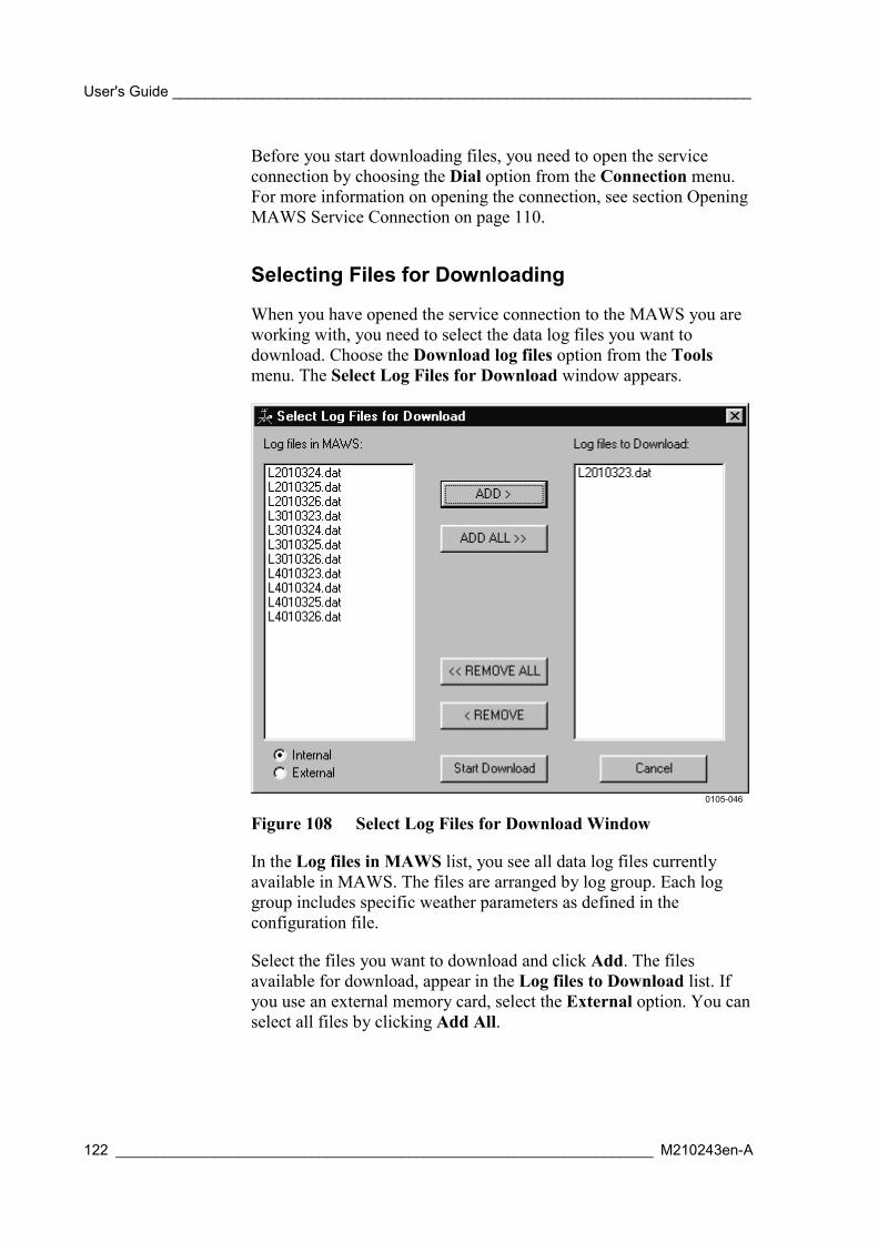
User's Guide _______________________________________________________________________
122 __________________________________________________________________ M210243en-A
Before you start downloading files, you need to open the serviceconnection by choosing the Dial option from the Connection menu.For more information on opening the connection, see section OpeningMAWS Service Connection on page 110.
Selecting Files for Downloading
When you have opened the service connection to the MAWS you areworking with, you need to select the data log files you want todownload. Choose the Download log files option from the Toolsmenu. The Select Log Files for Download window appears.
0105-046
Figure 108 Select Log Files for Download Window
In the Log files in MAWS list, you see all data log files currentlyavailable in MAWS. The files are arranged by log group. Each loggroup includes specific weather parameters as defined in theconfiguration file.
Select the files you want to download and click Add. The filesavailable for download, appear in the Log files to Download list. Ifyou use an external memory card, select the External option. You canselect all files by clicking Add All.
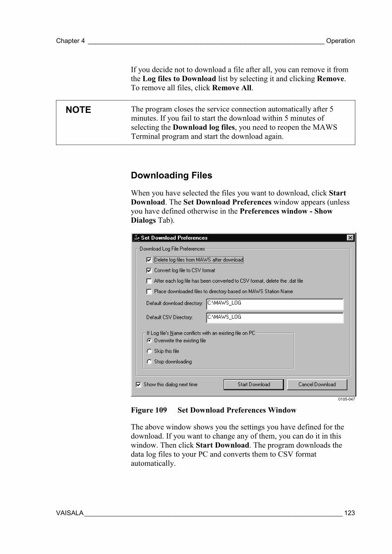
Chapter 4 _________________________________________________________________ Operation
VAISALA_______________________________________________________________________ 123
If you decide not to download a file after all, you can remove it fromthe Log files to Download list by selecting it and clicking Remove.To remove all files, click Remove All.
NOTE The program closes the service connection automatically after 5minutes. If you fail to start the download within 5 minutes ofselecting the Download log files, you need to reopen the MAWSTerminal program and start the download again.
Downloading Files
When you have selected the files you want to download, click StartDownload. The Set Download Preferences window appears (unlessyou have defined otherwise in the Preferences window - ShowDialogs Tab).
0105-047
Figure 109 Set Download Preferences Window
The above window shows you the settings you have defined for thedownload. If you want to change any of them, you can do it in thiswindow. Then click Start Download. The program downloads thedata log files to your PC and converts them to CSV formatautomatically.
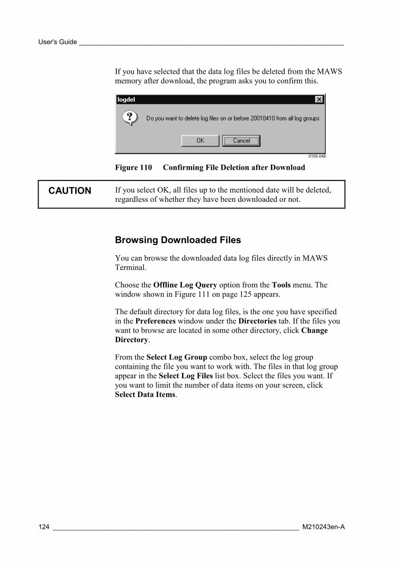
User's Guide _______________________________________________________________________
124 __________________________________________________________________ M210243en-A
If you have selected that the data log files be deleted from the MAWSmemory after download, the program asks you to confirm this.
0105-048
Figure 110 Confirming File Deletion after Download
CAUTION If you select OK, all files up to the mentioned date will be deleted,regardless of whether they have been downloaded or not.
Browsing Downloaded Files
You can browse the downloaded data log files directly in MAWSTerminal.
Choose the Offline Log Query option from the Tools menu. Thewindow shown in Figure 111 on page 125 appears.
The default directory for data log files, is the one you have specifiedin the Preferences window under the Directories tab. If the files youwant to browse are located in some other directory, click ChangeDirectory.
From the Select Log Group combo box, select the log groupcontaining the file you want to work with. The files in that log groupappear in the Select Log Files list box. Select the files you want. Ifyou want to limit the number of data items on your screen, clickSelect Data Items.
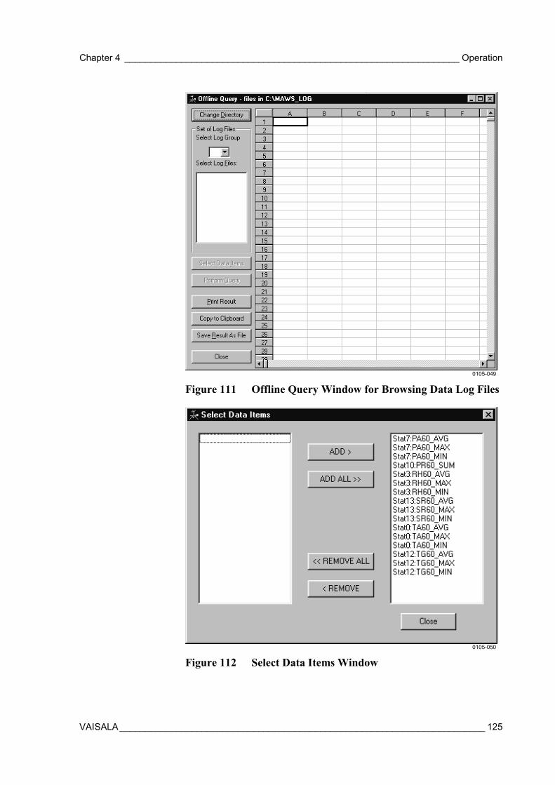
Chapter 4 _________________________________________________________________ Operation
VAISALA_______________________________________________________________________ 125
0105-049
Figure 111 Offline Query Window for Browsing Data Log Files
0105-050
Figure 112 Select Data Items Window
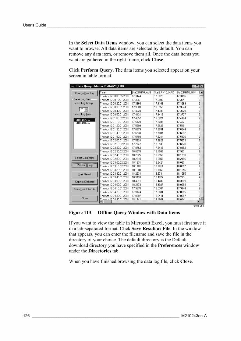
User's Guide _______________________________________________________________________
126 __________________________________________________________________ M210243en-A
In the Select Data Items window, you can select the data items youwant to browse. All data items are selected by default. You canremove any data item, or remove them all. Once the data items youwant are gathered in the right frame, click Close.
Click Perform Query. The data items you selected appear on yourscreen in table format.
0105-051
Figure 113 Offline Query Window with Data Items
If you want to view the table in Microsoft Excel, you must first save itin a tab-separated format. Click Save Result as File. In the windowthat appears, you can enter the filename and save the file in thedirectory of your choice. The default directory is the Defaultdownload directory you have specified in the Preferences windowunder the Directories tab.
When you have finished browsing the data log file, click Close.

Chapter 4 _________________________________________________________________ Operation
VAISALA_______________________________________________________________________ 127
Converting Data Log Files to CSV Format
If you have selected the Convert file to CSV format option in thePreferences window, Download tab, the program converts the datalog files into CSV format as you download them. However, if youprefer to download the files without converting them, you can do thisby choosing the Convert files to CSV option from the Tools menu.
When you select the Convert files to CSV option, the followingwindow appears.
0105-052
Figure 114 Selecting a Binary Log File for CSV Conversion
Select the file you want to convert to CSV format and click Open.The program starts the conversion. When the conversion is complete,the CSV file is saved in the directory you have specified in thePreferences window under the Directories tab.
Using External Memory CardThe external memory card is used to store log files that have beencopied or moved from the internal log directory. The data can beretrieved from the external memory card via terminal connection or byswitching the memory card with an empty one.
Note that the memory card must be formatted with a commandEXTFS ERASE before use.
The external memory card can be removed from MAWS for dataretrieval without interruptions to MAWS operations. MAWS copies
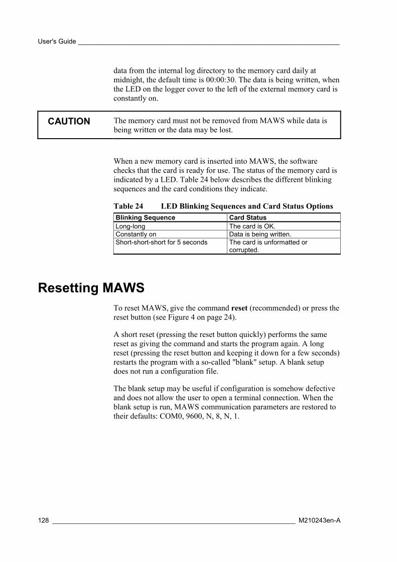
User's Guide _______________________________________________________________________
128 __________________________________________________________________ M210243en-A
data from the internal log directory to the memory card daily atmidnight, the default time is 00:00:30. The data is being written, whenthe LED on the logger cover to the left of the external memory card isconstantly on.
CAUTION The memory card must not be removed from MAWS while data isbeing written or the data may be lost.
When a new memory card is inserted into MAWS, the softwarechecks that the card is ready for use. The status of the memory card isindicated by a LED. Table 24 below describes the different blinkingsequences and the card conditions they indicate.
Table 24 LED Blinking Sequences and Card Status OptionsBlinking Sequence Card StatusLong-long The card is OK.Constantly on Data is being written.Short-short-short for 5 seconds The card is unformatted or
corrupted.
Resetting MAWSTo reset MAWS, give the command reset (recommended) or press thereset button (see Figure 4 on page 24).
A short reset (pressing the reset button quickly) performs the samereset as giving the command and starts the program again. A longreset (pressing the reset button and keeping it down for a few seconds)restarts the program with a so-called "blank" setup. A blank setupdoes not run a configuration file.
The blank setup may be useful if configuration is somehow defectiveand does not allow the user to open a terminal connection. When theblank setup is run, MAWS communication parameters are restored totheir defaults: COM0, 9600, N, 8, N, 1.

Chapter 4 _________________________________________________________________ Operation
VAISALA_______________________________________________________________________ 129
Command Reference for Terminal ConnectionTable 25 Command Set
Command Descriptionaltitude altitude [meters]. To see the current station altitude, type altitude. To
change the altitude, type altitude and the new station altitude in metersfrom sea level.
battery battery [capacity] sets the capacity of the internal battery, needed forMAWS internal control. Accepted capacity values are 1.2 ... 24 Ah. To seethe battery status, type battery.
cd cd [directory path] changes the current directory. cd / gets you back to theroot directory.NOTE! cd .. Cannot be used.
chmod chmod <filename> <r/w/x> changes the file access attributes: read (r), write(w) or execute (x). The setup file "Basic/Advanced/Lowpower" needs tohave attributes rwx.
close Closes terminal connection.copy copy <source file> <destination file> copies a file to another location.del del <filename> deletes a specified file. Only files that have (w)rite access
attribute can be deleted (see command chmod).dir dir [file/path] displays a list of a directory's files and subdirectories, used
and free disk space. The file information includes name, access_attributes,time, date and size.
errors errors [clear]. To see active errors, type errors. To clear active errors, typeerrors clear. Errors indicate that there is something wrong in the software.
EXTFS EXTFS <INFO|ERASE>. To format Compact Flash card, type EXTFSERASE. To show card info, type EXTFS INFO.NOTE! The command must be written in upper case.
help help [command] displays a command syntax. To list all the availablecommands, type help.
LASTVAL LASTVAL [Measurement] [raw | Signal name] shows the measured valuebefore any validation and the status produced during validation. Thevalidated value is shown when you give the signal name.
logdel logdel <log_group_id> <lastdate (dYYMMDD)> deletes a log file/files datedearlier than the last given date.
LOGFS LOGFS <ERASE> erases all data in the log system and resets MAWS.NOTE! The command must be written in upper case.
loggo loggo <log_group_id> starts logging of the defined log group.logshow logshow <log_group_id> [start (YYMMDDHH)] [count] [item numbers]
logshow L1 shows one line of current daylogshow L1 40 shows 40 lineslogshow L1 40 3 shows 40 lines of item 3logshow L1 001120 10 shows 10 lines starting from 20.11.2000
logshownext logshownext <log_group_id> [count]. After the logshow command, can beused to show the immediately following (later) log entries.
logshowprev logshowprev <log_group_id> [count]. After the logshow command, can beused to show the immediately preceding (earlier) log entries.
logstatus logstatus [log_group_id] shows logging state and variables of the definedlog group. The command without parameters shows statuses of all loggroups.
logstop logstop <log_group_id> stops logging of the defined log group.md md <path> creates directory. E.g. md /Ext/logdatamove move <source file> <destination file> copies a file to another location and
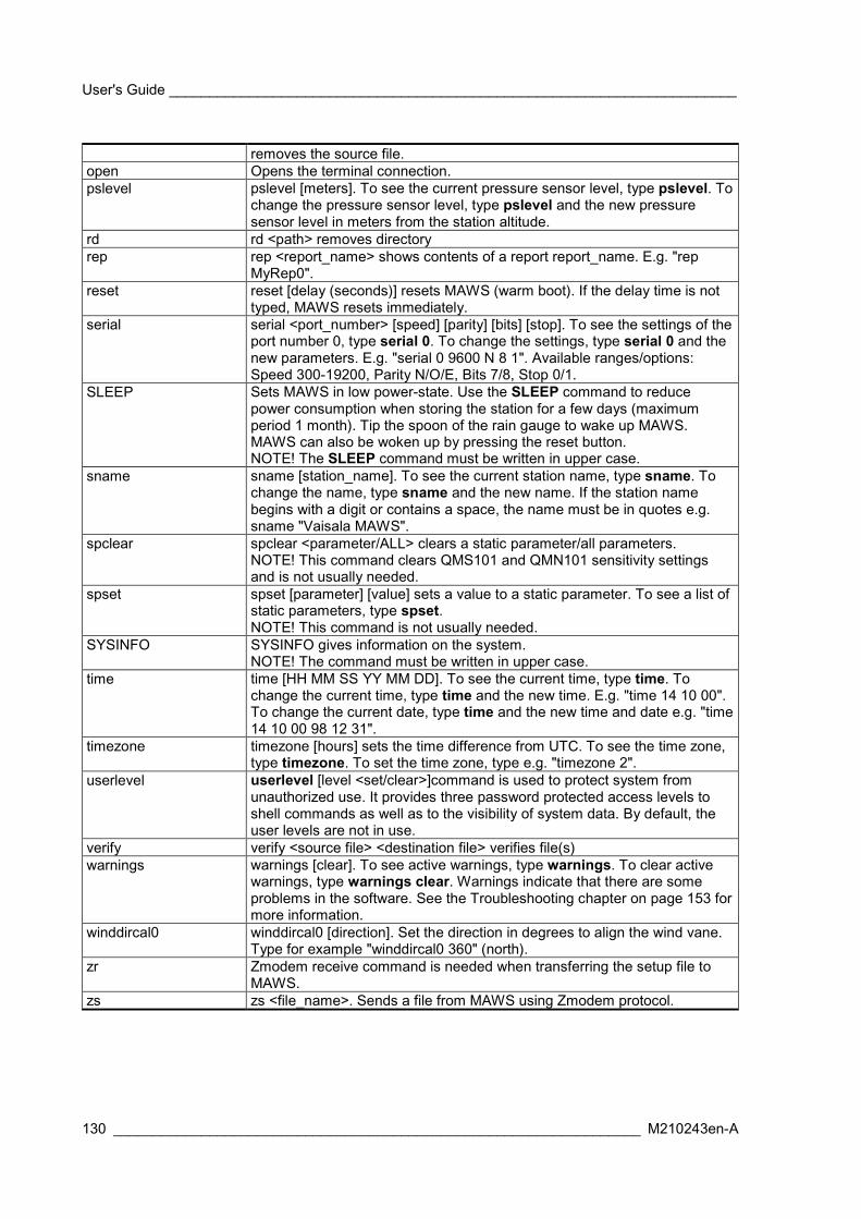
User's Guide _______________________________________________________________________
130 __________________________________________________________________ M210243en-A
removes the source file.open Opens the terminal connection.pslevel pslevel [meters]. To see the current pressure sensor level, type pslevel. To
change the pressure sensor level, type pslevel and the new pressuresensor level in meters from the station altitude.
rd rd <path> removes directoryrep rep <report_name> shows contents of a report report_name. E.g. "rep
MyRep0".reset reset [delay (seconds)] resets MAWS (warm boot). If the delay time is not
typed, MAWS resets immediately.serial serial <port_number> [speed] [parity] [bits] [stop]. To see the settings of the
port number 0, type serial 0. To change the settings, type serial 0 and thenew parameters. E.g. "serial 0 9600 N 8 1". Available ranges/options:Speed 300-19200, Parity N/O/E, Bits 7/8, Stop 0/1.
SLEEP Sets MAWS in low power-state. Use the SLEEP command to reducepower consumption when storing the station for a few days (maximumperiod 1 month). Tip the spoon of the rain gauge to wake up MAWS.MAWS can also be woken up by pressing the reset button.NOTE! The SLEEP command must be written in upper case.
sname sname [station_name]. To see the current station name, type sname. Tochange the name, type sname and the new name. If the station namebegins with a digit or contains a space, the name must be in quotes e.g.sname "Vaisala MAWS".
spclear spclear <parameter/ALL> clears a static parameter/all parameters.NOTE! This command clears QMS101 and QMN101 sensitivity settingsand is not usually needed.
spset spset [parameter] [value] sets a value to a static parameter. To see a list ofstatic parameters, type spset.NOTE! This command is not usually needed.
SYSINFO SYSINFO gives information on the system.NOTE! The command must be written in upper case.
time time [HH MM SS YY MM DD]. To see the current time, type time. Tochange the current time, type time and the new time. E.g. "time 14 10 00".To change the current date, type time and the new time and date e.g. "time14 10 00 98 12 31".
timezone timezone [hours] sets the time difference from UTC. To see the time zone,type timezone. To set the time zone, type e.g. "timezone 2".
userlevel userlevel [level <set/clear>]command is used to protect system fromunauthorized use. It provides three password protected access levels toshell commands as well as to the visibility of system data. By default, theuser levels are not in use.
verify verify <source file> <destination file> verifies file(s)warnings warnings [clear]. To see active warnings, type warnings. To clear active
warnings, type warnings clear. Warnings indicate that there are someproblems in the software. See the Troubleshooting chapter on page 153 formore information.
winddircal0 winddircal0 [direction]. Set the direction in degrees to align the wind vane.Type for example "winddircal0 360" (north).
zr Zmodem receive command is needed when transferring the setup file toMAWS.
zs zs <file_name>. Sends a file from MAWS using Zmodem protocol.
Chapter 4 _________________________________________________________________ Operation
VAISALA_______________________________________________________________________ 131
NOTE Winddircal0, ADCAL6, and ADCAL1 commands are availableonly when MAWS has a setup file loaded and running.
NOTE The following commands allow the use of wild cards: chmod, dir,del, copy, move, verify, zs.
Example:dir L1*.*copy /log/L2*.* /Ext/log_L2chmod *.* rw
NOTE File commands (dir, del, copy, move, and verify) can be aborted bytyping CTRL+C.

User's Guide _______________________________________________________________________
132 __________________________________________________________________ M210243en-A
This page intentionally left blank.
Chapter 5 _______________________________________________________________Maintenance
VAISALA_______________________________________________________________________ 133
CHAPTER 5
MAINTENANCE
This chapter provides information that is needed in the basicmaintenance of MAWS.
The purpose of periodic maintenance is to keep sensors operationaland safe, measurements reliable, and to define if any calibrationactions are needed.
Under normal conditions, the MAWS weather station needs only aminimum amount of maintenance. The need for maintenance dependson the sensors that are connected to your MAWS.
CAUTION Do not open the MAWS logger housing under poor conditions (forexample, rain or dust in the air). In general, it is not advisable torepair sensors in the field.
Routine Maintenance and CalibrationRegular maintenance of the MAWS system, its sensors, andaccessories is essential to ensure the correctness of the data and toextend the lifetime of the system. Periodic routine maintenance tasksinclude checking, cleaning, and servicing all the system elements andrepairing or replacing the damaged or worn-out components.
The maintenance task should be accomplished only by a technicianproperly trained for these tasks. The technician must be familiar withthe system and know how each component of the system performs. Inaddition, adequate tools and test equipment have to be at hand tocomplete the maintenance tasks successfully.
User's Guide _______________________________________________________________________
134 __________________________________________________________________ M210243en-A
When using high quality sensors and system, most of the routinemaintenance tasks can be performed at the installation site. Someinstruments and advanced calibrations and refurbishments, require thesensor be returned to the laboratory for proper calibration. Whensystem components need to be brought in from the field, the bestprocedure is to maintain an inventory of spare components. The usercan then exchange a component with a calibrated component or sensorduring a single visit. This is the case especially with sensors that mustbe returned to the manufacturer for calibration.
Before the maintenance actions, certain preparations must be made inorder to make the work successful:
- Obtain information on how the site has been functioning before thescheduled maintenance.
- Obtain information on what maintenance tasks were completedduring the previous maintenance procedure.
- Make sure that you have all the necessary tools available. Therequired set of tools depends on the system configuration, howeverthe minimum is listed below:
- A laptop PC with multiple fully charged batteries.
- The latest operational versions of the MAWS operatingsoftware version, MAWS Lizard Setup Software, and MAWSTerminal software.
- The configuration file which is used at that particular stationto be maintained.
- All the necessary system documentation.
- MAWS Terminal cable (QMZ101).
- Hand held tools; screw drivers, wrenches, pliers, wire cutters,and insulation strippers.
- Digital multimeter.
- Clean cloth, cleaning solution, and cleaning brush.
- Lubricant.
- Anti-seize compound.
- Safety harness, if tower climbing is required.
- All the necessary parts to be changed regularly.
- Make a list of all the sensors requiring replacement withrefurbished and calibrated units.
Chapter 5 _______________________________________________________________Maintenance
VAISALA_______________________________________________________________________ 135
Overall Checking- Check signal and main cables, connectors, and connections.
- Check gaskets of the enclosures.
- Check all grounding cables, lugs, etc.
- Check mechanical assemblies, bolts, nuts, etc.
- Check for corrosion. Repair if needed.
NOTE Use the correct tools of good quality.
Sensors and Accessories
Solar PanelInspect the module twice a year for overall integrity. Make sure thatconnections to the battery are tight and free of corrosion.
Dirt accumulation on the module's front surface can reduce the lightenergy collected by the module. If the module surface is dirty, gentlyclean it with a soft cloth or sponge using water and mild detergent.
WARNING Wear rubber gloves to protect yourself against possible electricshock.
CAUTION Do not use a scrub brush; it can damage the module front surface.
Wind SensorIt is recommended to check the ball bearings of the anemometer andthe vane every year. If the cup wheel or the vane is not rotatingsmoothly or creates detectable noise, the bearings must be replaced(refer to Figure 115 on page 137).

User's Guide _______________________________________________________________________
136 __________________________________________________________________ M210243en-A
Anemometer bearings:
1. Loosen the hubnut (14) with fingers or a 10-mm tool andremove the cup wheel (13).
2. Remove the ball bearing assembly (12) by unscrewing itcounterclockwise (with a 10-mm tool).
3. Insert a new bearing assembly (12) and tighten gently.
4. Fasten the cup wheel to the sensor and tighten gently.
Vane bearings:
1. Proceed as described in steps 1 and 2 above.
2. Open the lock screw (11) of the assembly (10) and remove it.
3. Remove the Seeger-ring (9) (with narrow point pliers).
4. Remove the bearing assembly (8).
5. Replace the bearings inside the housing with new ones.
6. Assemble the sensor in the reverse work order.
Due to normal wear, it may become necessary to renew the directionpotentiometer or the anemometer electronics assembly.
1. Remove the sensor housing parts.
2. Open the body (1+6) by unscrewing it clockwise.
3. To replace the potentiometer, proceed as follows:
a. Pull the potentiometer PCB (2b) out from the sleeve (4).
b. Unsolder the potentiometer wires from the PCB.
c. Solder new potentiometer wires to the PCB.
d. Push the PCB (2b) into the plastic sleeve (4) by pressingthe sleeve sides. Note the guide holes.
4. To replace the reed-switch PCB, proceed as follows:
a. Pull out the retainer flange (3) and the reed-switch PCB(2b).
b. Unsolder the old wires and solder new ones for the PCB.
c. Push the PCB into the tube of the casing (1).
d. Fit the flat wire to the groove at the casing wall and insertthe retainer flange. Make sure that the flat wire is pressedtightly against the casing wall.
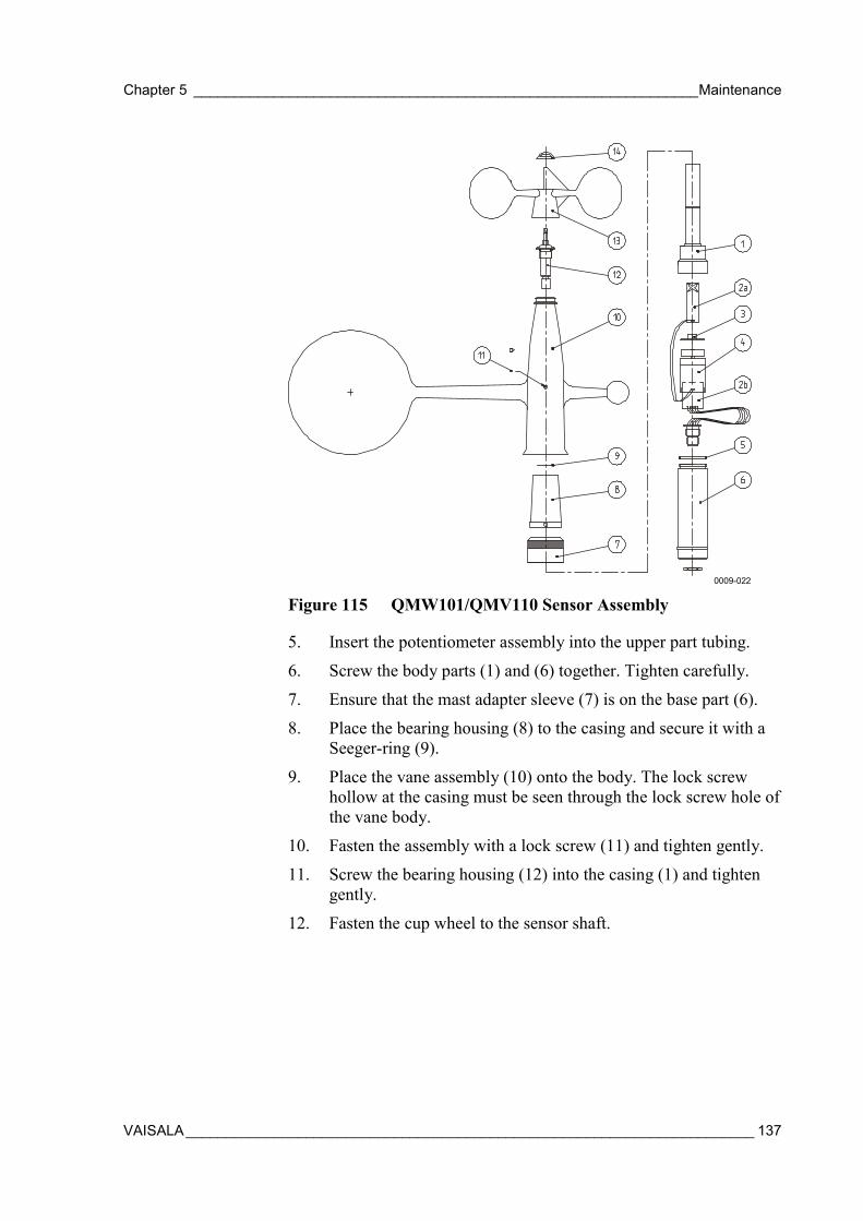
Chapter 5 _______________________________________________________________Maintenance
VAISALA_______________________________________________________________________ 137
0009-022
Figure 115 QMW101/QMV110 Sensor Assembly
5. Insert the potentiometer assembly into the upper part tubing.
6. Screw the body parts (1) and (6) together. Tighten carefully.
7. Ensure that the mast adapter sleeve (7) is on the base part (6).
8. Place the bearing housing (8) to the casing and secure it with aSeeger-ring (9).
9. Place the vane assembly (10) onto the body. The lock screwhollow at the casing must be seen through the lock screw hole ofthe vane body.
10. Fasten the assembly with a lock screw (11) and tighten gently.
11. Screw the bearing housing (12) into the casing (1) and tightengently.
12. Fasten the cup wheel to the sensor shaft.
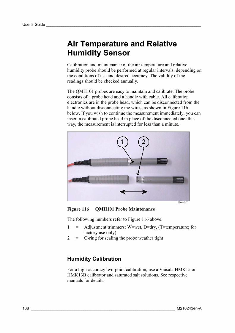
User's Guide _______________________________________________________________________
138 __________________________________________________________________ M210243en-A
Air Temperature and RelativeHumidity SensorCalibration and maintenance of the air temperature and relativehumidity probe should be performed at regular intervals, depending onthe conditions of use and desired accuracy. The validity of thereadings should be checked annually.
The QMH101 probes are easy to maintain and calibrate. The probeconsists of a probe head and a handle with cable. All calibrationelectronics are in the probe head, which can be disconnected from thehandle without disconnecting the wires, as shown in Figure 116below. If you wish to continue the measurement immediately, you caninsert a calibrated probe head in place of the disconnected one; thisway, the measurement is interrupted for less than a minute.
0201-047
Figure 116 QMH101 Probe Maintenance
The following numbers refer to Figure 116 above.
1 = Adjustment trimmers: W=wet, D=dry, (T=temperature; forfactory use only)
2 = O-ring for sealing the probe weather tight
Humidity Calibration
For a high-accuracy two-point calibration, use a Vaisala HMK15 orHMK13B calibrator and saturated salt solutions. See respectivemanuals for details.

Chapter 5 _______________________________________________________________Maintenance
VAISALA_______________________________________________________________________ 139
Leave the calibrator and the probe head in the same space for at leastfour hours so that their temperatures have time to equalize. Unscrewthe plastic grid of the probe.
The calibration is done first for the dry end (<50 %RH) and then forthe wet end (>50 %RH) by adjusting the trimmer potentiometersmarked with D and W. The potentiometers are located under aprotective plug, see Figure 116 on page 138. Use a ceramicscrewdriver with 2.5 mm blade for adjusting the potentiometers. Note:if zero point is calibrated in Nitrogen (N2), the minimum output signalof 0.008 V corresponds to a relative humidity of 0.8 %RH.
Table 26 Greenspan’s CalibrationTemperature [°°°°C] 15 20 25 30 35LiCl [%RH] *) 11.3 11.3 11.3 11.3NaCl [%RH] 75.6 75.5 75.3 75.1 74.9K2SO4 [%RH] 97.9 97.6 97.3 97.0 96.7
*) Do not use or store the LiCl solution in temperatures below +18 °C as its humidityequilibrium may change permanently.
As the D (dry) and W (wet) adjustments may affect each other, re-check the humidity reading at the low end. If necessary, repeat theadjustments in both the low and the high humidity points, until thereading is correct.
Changing the HUMICAP®180 Humidity Sensor
Unscrew the filter. Remove the damaged sensor and mount a newHUMICAP®180 humidity sensor in its place. Handle the sensor withcare. Calibrate the probe using a two-point calibration procedure. Notethat if the probe is not calibrated, the accuracy is still better than±7 %RH.
Pressure SensorUnder normal operating conditions, PMT16A Pressure Sensor needsonly a minimum amount of maintenance.
- Keep the pressure port clean.
- Annually, compare pressure values against a calibrated portablestandard.

User's Guide _______________________________________________________________________
140 __________________________________________________________________ M210243en-A
Calibration
The MAWS software provides means for one-point field calibration ofPMT16A. Required equipment:
- Laptop PC with a terminal software
- A standard barometer (for example Vaisala PTB220TS)
- Terminal cable QMZ101 (delivered with MAWS).
Table 27 Calibration ProcedureStep Action Command/note1. Establish terminal connection to MAWS by
connecting the terminal cable betweenCOM0 port of MAWS and a COM port onyour PC.
For more information, refer to sectionEstablishing Terminal Connection on page104.
2. Place both pressure sensors at the samelevel.
NOTE! Make sure that the wind does notinterfere with the reading of the referencebarometer.
3. Read the reference barometer reading.4. Give this reference reading, for example
1003.7 hPa, to MAWS.Type:PMT16CAL 1003.7
5. Check the readings given by MAWS. Value = (reference reading)Measured value = measured by MAWSOffset = measured value - reference reading
6. Repeat the calibration if necessary.7. Close the terminal connection. Give command close
Precipitation Sensors
QMR101
To ensure reliable and accurate measurements, we recommend that thefollowing checks be carried out at each visit to the rain gauge.
NOTE If the gauge is still connected to the data logger and logger isoperating, care must be taken to avoid tipping the spoon/bucket whencarrying out the following operations.
1. Inspect the funnel for any damage or blockage. At certain timesof year, leaves may have accumulated into the funnel. Dirt anddust can also block the grille preventing or reducing the flowrate to a slow drip to the buckets beneath. Remove all obstaclesfrom the funnel.
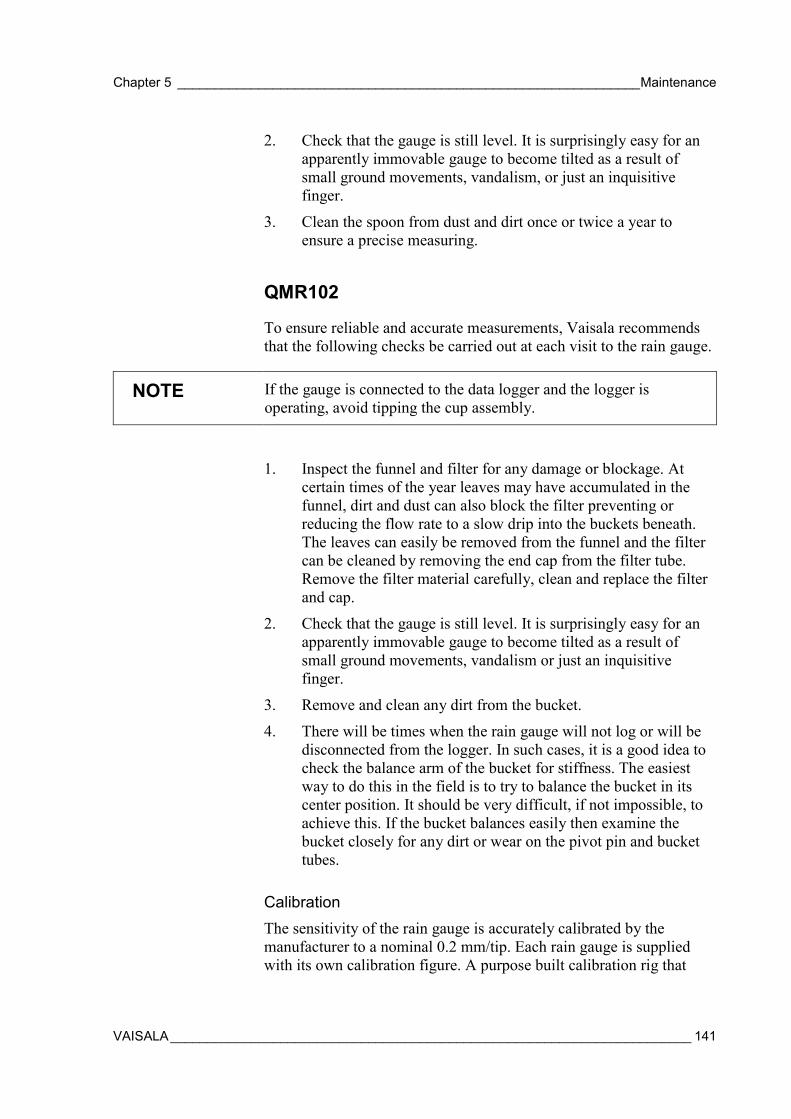
Chapter 5 _______________________________________________________________Maintenance
VAISALA_______________________________________________________________________ 141
2. Check that the gauge is still level. It is surprisingly easy for anapparently immovable gauge to become tilted as a result ofsmall ground movements, vandalism, or just an inquisitivefinger.
3. Clean the spoon from dust and dirt once or twice a year toensure a precise measuring.
QMR102
To ensure reliable and accurate measurements, Vaisala recommendsthat the following checks be carried out at each visit to the rain gauge.
NOTE If the gauge is connected to the data logger and the logger isoperating, avoid tipping the cup assembly.
1. Inspect the funnel and filter for any damage or blockage. Atcertain times of the year leaves may have accumulated in thefunnel, dirt and dust can also block the filter preventing orreducing the flow rate to a slow drip into the buckets beneath.The leaves can easily be removed from the funnel and the filtercan be cleaned by removing the end cap from the filter tube.Remove the filter material carefully, clean and replace the filterand cap.
2. Check that the gauge is still level. It is surprisingly easy for anapparently immovable gauge to become tilted as a result ofsmall ground movements, vandalism or just an inquisitivefinger.
3. Remove and clean any dirt from the bucket.
4. There will be times when the rain gauge will not log or will bedisconnected from the logger. In such cases, it is a good idea tocheck the balance arm of the bucket for stiffness. The easiestway to do this in the field is to try to balance the bucket in itscenter position. It should be very difficult, if not impossible, toachieve this. If the bucket balances easily then examine thebucket closely for any dirt or wear on the pivot pin and buckettubes.
CalibrationThe sensitivity of the rain gauge is accurately calibrated by themanufacturer to a nominal 0.2 mm/tip. Each rain gauge is suppliedwith its own calibration figure. A purpose built calibration rig that
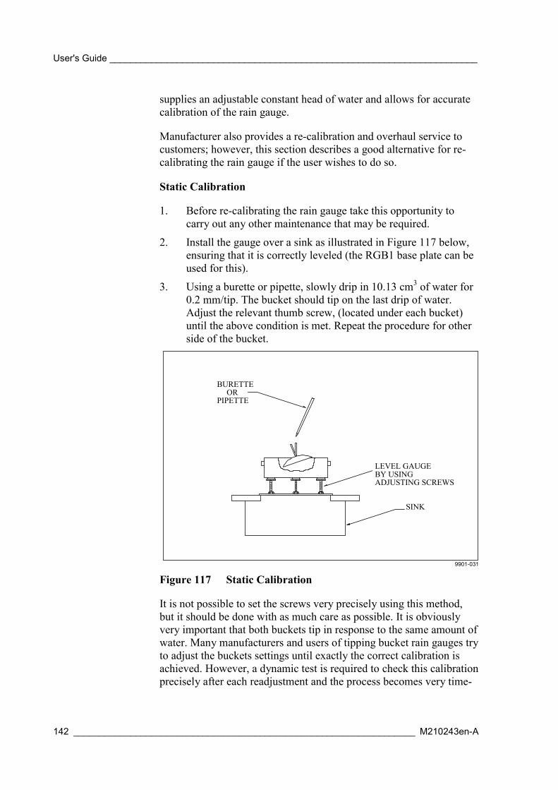
User's Guide _______________________________________________________________________
142 __________________________________________________________________ M210243en-A
supplies an adjustable constant head of water and allows for accuratecalibration of the rain gauge.
Manufacturer also provides a re-calibration and overhaul service tocustomers; however, this section describes a good alternative for re-calibrating the rain gauge if the user wishes to do so.
Static Calibration
1. Before re-calibrating the rain gauge take this opportunity tocarry out any other maintenance that may be required.
2. Install the gauge over a sink as illustrated in Figure 117 below,ensuring that it is correctly leveled (the RGB1 base plate can beused for this).
3. Using a burette or pipette, slowly drip in 10.13 cm3 of water for0.2 mm/tip. The bucket should tip on the last drip of water.Adjust the relevant thumb screw, (located under each bucket)until the above condition is met. Repeat the procedure for otherside of the bucket.
PIPETTEOR
BURETTE
LEVEL GAUGEBY USINGADJUSTING SCREWS
SINK
9901-031
Figure 117 Static Calibration
It is not possible to set the screws very precisely using this method,but it should be done with as much care as possible. It is obviouslyvery important that both buckets tip in response to the same amount ofwater. Many manufacturers and users of tipping bucket rain gauges tryto adjust the buckets settings until exactly the correct calibration isachieved. However, a dynamic test is required to check this calibrationprecisely after each readjustment and the process becomes very time-
Chapter 5 _______________________________________________________________Maintenance
VAISALA_______________________________________________________________________ 143
consuming. In any case, it is virtually impossible to get theadjustments absolutely correct, and it is generally preferable to adjustthe settings as closely as is reasonably practical, and then derive acalibration factor for each rain gauge individually after dynamiccalibration.
Dynamic Calibration
1. Configure the gauge as shown in Figure 118 below or Figure119 on page 144 (the latter setup will give a preferable constantflow rate), ensure the gauge is leveled and connected to a datalogger or counter.
2. Fill a container with 1000 cm3 of water for 0.2 mm/tipcalibration. This is usually achieved most precisely andconsistently by weighing the water on a balance capable ofmeasuring to 0.1 g (0.1 cm3). An alternative is to use a goodquality graduated measuring cylinder.
3. Allow the water to drip slowly into the gauge, taking at least 60minutes to empty (approximately 40 seconds for each tip). Atthe end of this period approximately 98 tips will have occurred.The exact number is obtained from the data logger or counter.To this, add on an accurate estimation of what fraction of a tip isleft in the bucket when the water stops flowing (a graduatedsyringe is ideal for this).
WATER IN OPENTOP CONTAINER
FLOWADJUSTMENT
LEVEL GAUGEBY USINGADJUSTING SCREWS
SINK
9901-032
Figure 118 Dynamic Calibration
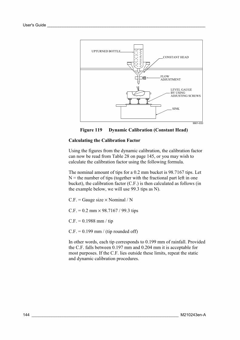
User's Guide _______________________________________________________________________
144 __________________________________________________________________ M210243en-A
FLOWADJUSTMENT
LEVEL GAUGEBY USINGADJUSTING SCREWS
SINK
UPTURNED BOTTLE
CONSTANT HEAD
9901-033
Figure 119 Dynamic Calibration (Constant Head)
Calculating the Calibration Factor
Using the figures from the dynamic calibration, the calibration factorcan now be read from Table 28 on page 145, or you may wish tocalculate the calibration factor using the following formula.
The nominal amount of tips for a 0.2 mm bucket is 98.7167 tips. LetN = the number of tips (together with the fractional part left in onebucket), the calibration factor (C.F.) is then calculated as follows (inthe example below, we will use 99.3 tips as N).
C.F. = Gauge size × Nominal / N
C.F. = 0.2 mm × 98.7167 / 99.3 tips
C.F. = 0.1988 mm / tip
C.F. = 0.199 mm / (tip rounded off)
In other words, each tip corresponds to 0.199 mm of rainfall. Providedthe C.F. falls between 0.197 mm and 0.204 mm it is acceptable formost purposes. If the C.F. lies outside these limits, repeat the staticand dynamic calibration procedures.

Chapter 5 _______________________________________________________________Maintenance
VAISALA_______________________________________________________________________ 145
Table 28 Calibration FactorsNumber of tips C.F.96.7 to 96.9 0.204 mm/tip97.0 to 97.4 0.203 mm/tip97.5 to 97.9 0.202 mm/tip98.0 to 98.4 0.201 mm/tip98.5 to 98.9 0.200 mm/tip99.0 to 99.4 0.199 mm/tip99.5 to 99.9 0.198 mm/tip100 to 100.4 0.197 mm/tip
Solar Radiation Sensors
QMS101
The pyranometer is an all weather instrument.
Once installed the pyranometer needs little maintenance. It isrecommended that you clean the detector as part of a regular routine,using water or alcohol.
Re-calibration is suggested every two years. This can be done in twoways. The first is to compare with the measurement of a similar sensorat the same site. Preferably, daily totals of several days should becompared. Calibration factor could be corrected if results differ bymore than five percent. The second way is to let a re-calibration beperformed at the factory.
If necessary, the sensitivity of the pyranometer can be adjusted. Thiscan be done by soldering a resistor between the + (white) and - (black)output wires. In this way the pyranometer is shunted. For the standardpyranometer, the internal resistance is 47 Ω, and the cable resistance is0.12 Ω per meter. The cable is 3 meters long. The cable resistance hasto be multiplied by two, for the + and - wire. Total resistance is 47.7Ω. In order to reduce the sensitivity by a factor of 10, when the full 3meters of cable is used, a shunt resistor of 5.3 Ω can be made out of a1 and a 4.3 Ω resistor. The order of magnitude for the sensitivity willbe 10 µV/Wm-2.
The general formula for establishing the proper resistor for trimmingby a factor of 10 is [47 + (0.24 × cable length)]/9. The cable length isin meters and the resistance is in ohms.
User's Guide _______________________________________________________________________
146 __________________________________________________________________ M210243en-A
QMS102
The pyranometer is an all weather instrument. Once installed thepyranometer needs little maintenance. It is recommended that youclean the detector as part of a regular routine, using water or alcohol.
Re-calibration is suggested every two years. This can be done in twoways. The first is to compare with the measurement of a similar sensorat the same site. Daily totals of at least two days should be compared.Calibration factor should be corrected if results differ by more than sixper cent. The second way is to let a re-calibration be performed at thefactory.
QMN101
The net radiometer is an all weather instrument. Once installed itneeds little maintenance. It is recommended that you clean thedetector as part of a regular routine, using water or alcohol.
Re-calibration is suggested every two years, preferably by letting ahigher standard run parallel to it for two sunny days, and bycomparing the daily totals over several days. The calibration factorcould be corrected if the results differ by more than five percent. Thereference could be a net radiometer type CNR1, or a QMN101 that iskept safely in a cupboard.
Another way of checking sensor performance during field use is to putthe sensor upside down during stable atmospheric conditions.Theoretically, the sensor output should change sign. Please mind thatthe sensor response time for stabilizing is about one minute. Thismethod is no more accurate than 20% due to the fact that the sensorsymmetry is no more accurate than this.
A third way is to let a re-calibration be performed at the factory.
Soil Temperature Sensors
QMT103
The probe does no need any regular maintenance. Field repairs areaccomplished by replacing the complete probe.
Chapter 5 _______________________________________________________________Maintenance
VAISALA_______________________________________________________________________ 147
QMT107
When the probe is extracted, clean the dirt accumulation on theprobe's surface with a soft cloth or sponge using water and milddetergent. Field repairs are accomplished by replacing the completeprobe.
Soil Moisture SensorThe ML2x probe is sealed after the factory calibration. It does notrequire any routine maintenance and it is constructed of materialsselected for robust field operation. If the measurement rods becomebent in use, they can be carefully unscrewed from the body andstraightened. They have a right-handed thread. Please pay specialattention to the following points:
- Do not remove the cross-head sealing screws. This may damage theseal and will invalidate your guarantee. No internal maintenance orrepair shall be performed by the user.
- Do not remove the probe from soil by pulling on the cable.
- Do not attempt to straighten the measurement rods while they arestill attached to the probe body. This may break the rods or damagethe case seal.
Water Level Sensors
QMV101/QMV102
To ensure reliable and accurate measurements, we recommend thatduring each visit to the QMV101 Water Level Sensor the followingchecks be made:
1. Check the drying detergent through the window of the junctionbox.
2. If the drying detergent has turned red, change the cartridge. Thecartridge has reached its internal maximum absorption ofhumidity. Replace the cartridge and adjust the interval for thenext visit.
User's Guide _______________________________________________________________________
148 __________________________________________________________________ M210243en-A
CAUTION The drying detergent is very important to ensure reliable performanceof the water level sensor. Otherwise humidity enters the sensor casingthrough the ventilation pipe inside the cable and causes severedamage to the sensor.
Leaf Wetness SensorThe QLW101 Leaf Wetness Sensor does not need any regularmaintenance. Field repairs are accomplished by replacing thecomplete probe.
Fuel Moisture SensorThe sensing element of QFM101 Fuel Moisture sensor is a woodendowel that exchanges moisture with its surroundings. In the course ofa year, it undergoes many cycles of soaking up moisture and drying.These processes eventually cause the structure of the wood todeteriorate. Similarly, dust and other contaminants become imbeddedin the surface and they change the surface properties. When thisoccurs, the calibration is no longer valid.
The only way to restore the sensor accuracy is to replace the woodendowel, which must be done at the factory.
Your experience will eventually determine how frequently the sensorneeds service. At the beginning, the manufacturer recommends thatyou return it to the factory once a year for replacement of the doweland calibration.
At most sites, where the sensor is used to assess fire danger, there is aseason when the danger is low. That is usually a good time to replaceor refurbish the sensor.
Cable MaintenanceInspect cables for breaks, cracks in the protective coating or cableconnectors, and bent, damaged, or misaligned pins. Also wipe off orremove excess dirt, dust, sand, or leaves.
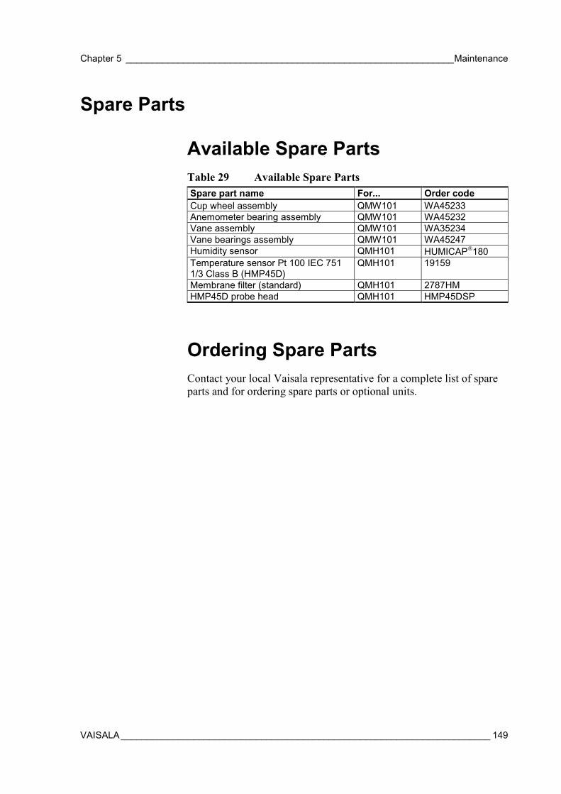
Chapter 5 _______________________________________________________________Maintenance
VAISALA_______________________________________________________________________ 149
Spare Parts
Available Spare PartsTable 29 Available Spare PartsSpare part name For... Order codeCup wheel assembly QMW101 WA45233Anemometer bearing assembly QMW101 WA45232Vane assembly QMW101 WA35234Vane bearings assembly QMW101 WA45247Humidity sensor QMH101 HUMICAP180Temperature sensor Pt 100 IEC 7511/3 Class B (HMP45D)
QMH101 19159
Membrane filter (standard) QMH101 2787HMHMP45D probe head QMH101 HMP45DSP
Ordering Spare PartsContact your local Vaisala representative for a complete list of spareparts and for ordering spare parts or optional units.

User's Guide _______________________________________________________________________
150 __________________________________________________________________ M210243en-A
This page intentionally left blank.

Chapter 6 ____________________________________________________________ Troubleshooting
VAISALA_______________________________________________________________________ 151
CHAPTER 6
TROUBLESHOOTING
This section consists of some common MAWS problems, theirprobable causes, and remedies.
Data ValidationFor most of the sensor inputs, there are data validation parameters tocheck the following measurement's quality parameters:
- Maximum value: the maximum climatological value for the sensormeasurement.
- Minimum value: the minimum climatological value for the sensormeasurement.
- Step change: the maximum step change for the sensor valuebetween two consecutive measurements.
All of these parameters can be set by the user using the MAWS Lizardsetup software. For more information, refer to the User's Guide listedin Table 2 on page 15.
If the sensor value is outside of the maximum or minimum values, orit has altered more than the maximum step change allowed, then datawill be flagged as INVALID. Invalid data is typically displayed as /////(this is a user settable parameter). If a sensor displays invalid data, thisis an indication that the sensor is faulty or out of calibration, or thereis a problem in powering or measuring the sensor.
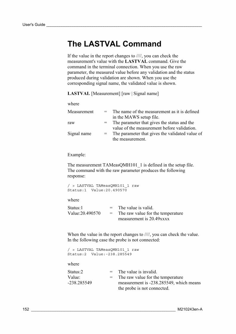
User's Guide _______________________________________________________________________
152 __________________________________________________________________ M210243en-A
The LASTVAL CommandIf the value in the report changes to ////, you can check themeasurement's value with the LASTVAL command. Give thecommand in the terminal connection. When you use the rawparameter, the measured value before any validation and the statusproduced during validation are shown. When you use thecorresponding signal name, the validated value is shown.
LASTVAL [Measurement] [raw | Signal name]
where
Measurement = The name of the measurement as it is definedin the MAWS setup file.
raw = The parameter that gives the status and thevalue of the measurement before validation.
Signal name = The parameter that gives the validated value ofthe measurement.
Example:
The measurement TAMeasQMH101_1 is defined in the setup file.The command with the raw parameter produces the followingresponse:
/ > LASTVAL TAMeasQMH101_1 rawStatus:1 Value:20.490570
where
Status:1 = The value is valid.Value:20.490570 = The raw value for the temperature
measurement is 20.49xxxx
When the value in the report changes to ////, you can check the value.In the following case the probe is not connected:
/ > LASTVAL TAMeasQMH101_1 rawStatus:2 Value:-238.285549
where
Status:2 = The value is invalid.Value:-238.285549
= The raw value for the temperaturemeasurement is -238.285549, which meansthe probe is not connected.
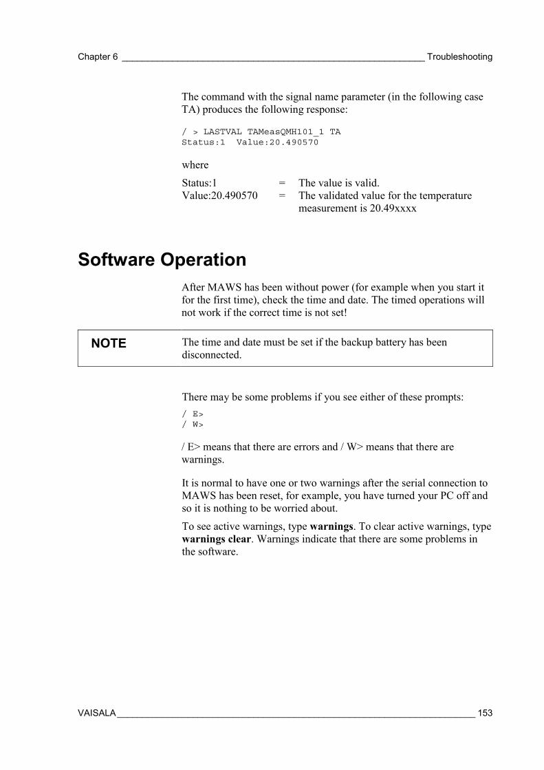
Chapter 6 ____________________________________________________________ Troubleshooting
VAISALA_______________________________________________________________________ 153
The command with the signal name parameter (in the following caseTA) produces the following response:
/ > LASTVAL TAMeasQMH101_1 TAStatus:1 Value:20.490570
where
Status:1 = The value is valid.Value:20.490570 = The validated value for the temperature
measurement is 20.49xxxx
Software OperationAfter MAWS has been without power (for example when you start itfor the first time), check the time and date. The timed operations willnot work if the correct time is not set!
NOTE The time and date must be set if the backup battery has beendisconnected.
There may be some problems if you see either of these prompts:/ E>/ W>
/ E> means that there are errors and / W> means that there arewarnings.
It is normal to have one or two warnings after the serial connection toMAWS has been reset, for example, you have turned your PC off andso it is nothing to be worried about.
To see active warnings, type warnings. To clear active warnings, typewarnings clear. Warnings indicate that there are some problems inthe software.
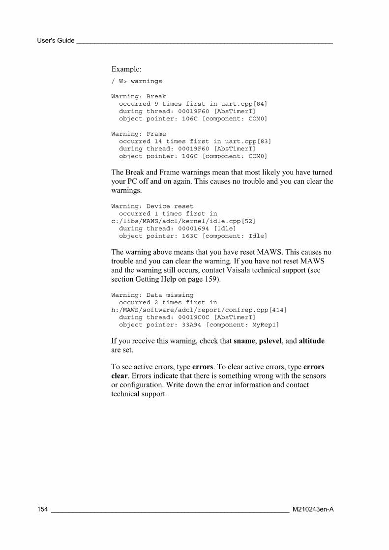
User's Guide _______________________________________________________________________
154 __________________________________________________________________ M210243en-A
Example:/ W> warnings
Warning: Breakoccurred 9 times first in uart.cpp[84]during thread: 00019F60 [AbsTimerT]object pointer: 106C [component: COM0]
Warning: Frameoccurred 14 times first in uart.cpp[83]during thread: 00019F60 [AbsTimerT]object pointer: 106C [component: COM0]
The Break and Frame warnings mean that most likely you have turnedyour PC off and on again. This causes no trouble and you can clear thewarnings.
Warning: Device resetoccurred 1 times first in
c:/libs/MAWS/adcl/kernel/idle.cpp[52]during thread: 00001694 [Idle]object pointer: 163C [component: Idle]
The warning above means that you have reset MAWS. This causes notrouble and you can clear the warning. If you have not reset MAWSand the warning still occurs, contact Vaisala technical support (seesection Getting Help on page 159).
Warning: Data missingoccurred 2 times first in
h:/MAWS/software/adcl/report/confrep.cpp[414]during thread: 00019C0C [AbsTimerT]object pointer: 33A94 [component: MyRep1]
If you receive this warning, check that sname, pslevel, and altitudeare set.
To see active errors, type errors. To clear active errors, type errorsclear. Errors indicate that there is something wrong with the sensorsor configuration. Write down the error information and contacttechnical support.

Chapter 6 ____________________________________________________________ Troubleshooting
VAISALA_______________________________________________________________________ 155
Table 30 Some Common Problems and Their RemediesProblem Probable Cause Remedy
Type open and press ENTER. The commandmust be typed exactly right before it can beexecuted.
The terminal connectionis not open.
Correct PC port and MAWS COM port settingsand check the cable connection.
MAWS will not open forcommands.
MAWS is not receivingpower.
Check connections and power supply. Checkthat the internal battery is connected.
MAWS is not sendinganything (nothing isseen on the screen).
Press and keep down the reset button for a fewseconds. MAWS will restart and display the text"Using blank configuration".Check your setup and upload it again to yourMAWS.
The Setup file does notexist in Cfg directory.
Copy or load the file to the correct directory.After reset, MAWSdisplays "!Erroneoussetup file". Setup file is not
executable.Type "chmod Filename rwx".
Nothing happens duringthe Zmodem transfer.
The terminal connectionhas failed.
Type CTRL+X (hold CTRL down and press X)five times.
After uploading a newsetup file, MAWSTerminal displays"Unhandled exceptionnumber: 39".
To solve the problem, consider removing somecalculations, or executing the calculations lessfrequently. You might, for example, avoidcalculations which are executed more frequentlythan the results are reported or logged.
Setup might include toomany calculations, thestatistical calculationsmay be too long, or theintervals between thestatistical calculations tooshort.
Purchase the memory expansion card, itcontains additional 512 kB RAM memory.
System InformationYou can acquire a report that contains system information by usingthe SYSINFO command in MAWS Terminal. The command listsmany parameters that are useful especially when troubleshooting thesystem or when contacting Vaisala HelpDesk.

User's Guide _______________________________________________________________________
156 __________________________________________________________________ M210243en-A
Example:
/ > SYSINFO
Serial # : 59289091Hardware : Rev FSoftware : 3.02 Checksum : 61577576System RAM : 1024kBFree memory : 583kBInternal temp. : 3.13'CActive errors : NOActive warnings : NOPiggyback - 0 : DSU232 rev: B serial no: 009513Piggyback - 1 : N/AExtension board : QMC102 rev: B serial no: V37306System uptime : 65h 20min 27sec since Fri Jan 1116:35:39 2002
/ >
where:
Serial # = The serial number of the logger PCB.Hardware = The hardware revision of the logger PCB.Software = The software version for the operating software
and it's checksum.System RAM = The total amount of the memory on the logger.Free memory = The amount of the free memory on the logger.Internal temp. = The internal temperature of the logger.Active errors = The existence of the active errors: YES/NOActivewarnings
= The existence of the active warnings: YES/NO
Piggyback - 0 = The type and serial number of the additionalmodule installed in the module slot 1.
Piggyback - 1 = The type and serial number of the additionalmodule installed in the module slot 2.
Extensionboard
= The type and serial number of the optionallyinstalled memory expansion board.
System uptime = The total time that the system has been running,calculated from the last reset.
Connection ProblemsIf you cannot connect to MAWS, the service connection is not openedand you cannot work with MAWS. In case of connection problems,check Table 31 on page 157.
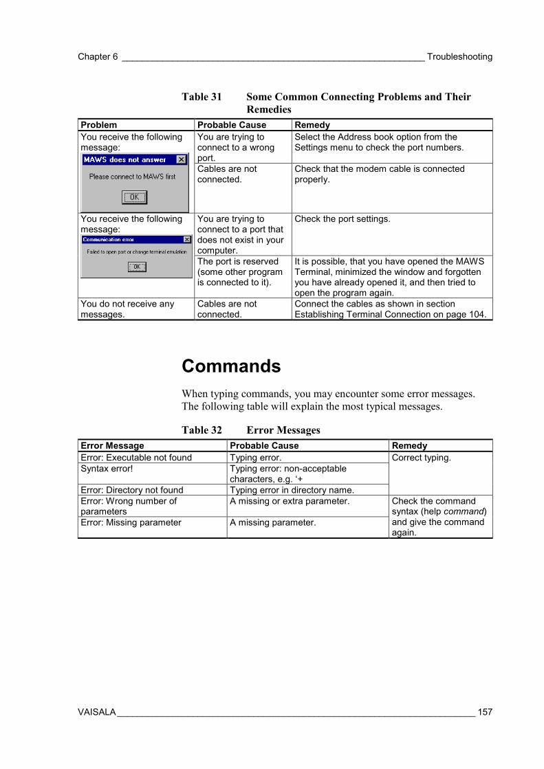
Chapter 6 ____________________________________________________________ Troubleshooting
VAISALA_______________________________________________________________________ 157
Table 31 Some Common Connecting Problems and TheirRemedies
Problem Probable Cause RemedyYou are trying toconnect to a wrongport.
Select the Address book option from theSettings menu to check the port numbers.
You receive the followingmessage:
Cables are notconnected.
Check that the modem cable is connectedproperly.
You are trying toconnect to a port thatdoes not exist in yourcomputer.
Check the port settings.You receive the followingmessage:
The port is reserved(some other programis connected to it).
It is possible, that you have opened the MAWSTerminal, minimized the window and forgottenyou have already opened it, and then tried toopen the program again.
You do not receive anymessages.
Cables are notconnected.
Connect the cables as shown in sectionEstablishing Terminal Connection on page 104.
CommandsWhen typing commands, you may encounter some error messages.The following table will explain the most typical messages.
Table 32 Error MessagesError Message Probable Cause RemedyError: Executable not found Typing error.Syntax error! Typing error: non-acceptable
characters, e.g. ‘+Error: Directory not found Typing error in directory name.
Correct typing.
Error: Wrong number ofparameters
A missing or extra parameter.
Error: Missing parameter A missing parameter.
Check the commandsyntax (help command)and give the commandagain.
User's Guide _______________________________________________________________________
158 __________________________________________________________________ M210243en-A
Battery StatusYou can view battery status information by giving the commandbattery without parameters.
Example:
/ > batteryRemaining=100State=FLOAT_CHARGEU=6.850195I=2.685547Type=PB_BATTERYCapacity=1.200000Ext.DC=8.132420Internal temperature=23.511668
Battery voltage (U) and voltage at the +ExtDC terminal are given asvolts, charging current (I) as milliamperes and capacity as ampere-hours. The remaining percentage shows how much energy is left in thebattery.
When is suspected that the internal battery or the charging circuitry isdefective, try the following:
- Check that the battery capacity is correct and change it withbattery <capacity> command, if necessary. If the capacity settingis too low, the battery simply charges slowly. In the opposite case,the battery may be damaged due to too high charging.
- Check the battery voltage, ExtDC voltage and charging current.ExtDC should be higher than battery voltage for charging. If it islower, battery is discharging and charging current shows negativevalue. Normally, battery voltage should vary between 5.8 and 7.0volts and it may rise as high as 7.5 volts during Quick Charge (forlead batteries).
Determining MAWS Operation ModeYou can look at the status LED to determine the MAWS operationmode. The LED is located on the MAWS logger board (see Figure 4on page 24). First, you have to open the tube as instructed in sectionInstalling MAWS Basic Components on page 53.

Chapter 6 ____________________________________________________________ Troubleshooting
VAISALA_______________________________________________________________________ 159
Table 33 Determining Operation Mode by LED FlashingLED flashing interval Operation mode NoteAll the time MAWS has been reset
but setup has not beenexamined yet.
Once per 5 seconds Setup running.Once per 10 seconds Blank boot or
configuration cannot berun.
Quickly 2 times Setup is running butthere are warnings.
Interval determined bysetup.
Quickly 3 times Setup is running butthere are errors.
Interval determined bysetup.
Not at all None. Check the powersupply!
Power Supply
Solar PanelTable 34 Troubleshooting the Solar PanelProblem Probable Cause RemedyThe power output hasdecreased.
The module surface isdirty
Gently clean it with asoft cloth or spongeusing water and milddetergent.
Getting HelpContact Vaisala technical support:
E-mail [email protected]
Telephone +358 9 8949 2789
Fax +358 9 8949 2790
User's Guide _______________________________________________________________________
160 __________________________________________________________________ M210243en-A
Return InstructionsIn case MAWS needs repair, please follow the instructions below tospeed up the process and avoid extra costs.
1. Read the warranty information.
2. With the returned component(s), write a Problem Report withname, e-mail, telephone number, and fax number of atechnically competent person, who can give additionalinformation about the problem.
3. On the Problem Report, please explain:
- What failed (what worked / did not work)?- Where did it fail (location and environment)?- When did it fail (date, from the beginning / after a while /
periodically / randomly)?- How many failed (only one defect / other same or similar
defects / several failures in one unit)?- What was connected to the product and to which connectors?- Input power source type, voltage and list of other items that
were connected to the same power output (lighting, heaters,motors etc.)?
- What was done after the failure was noticed?
4. Include a detailed return address with your preferred shippingmethod on the Problem Report.
5. Pack the product using good quality ESD protection bag withsuitable cushion material in a strong box of adequate size toprevent any shipping defects.
6. Include the Problem Report in the same box with the returnedproduct.
7. Send the box to:Vaisala OyjContact person / DivisionVanha Nurmijärventie 21FIN-01670 VantaaFinland

Chapter 7 _____________________________________________________________ Technical Data
VAISALA_______________________________________________________________________ 161
CHAPTER 7
TECHNICAL DATA
This chapter provides the technical data of MAWS and its sensors.
Connector Block DescriptionsThe MAWS logger includes:
1. Ten measurement channels and one internal channel for pressuremeasurement.
2. One connector block for power supplies.
3. One connector block for communication channel.
4. Two blocks for optional communication modules.
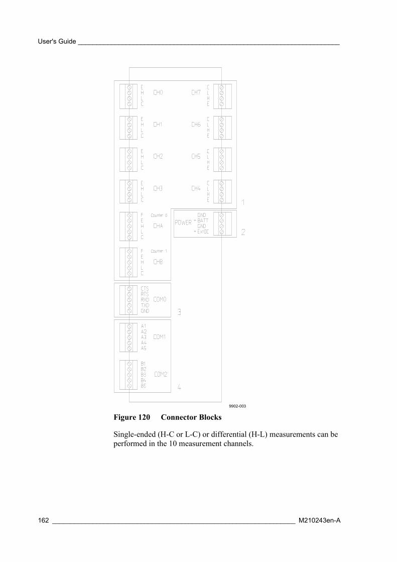
User's Guide _______________________________________________________________________
162 __________________________________________________________________ M210243en-A
9902-003
Figure 120 Connector Blocks
Single-ended (H-C or L-C) or differential (H-L) measurements can beperformed in the 10 measurement channels.
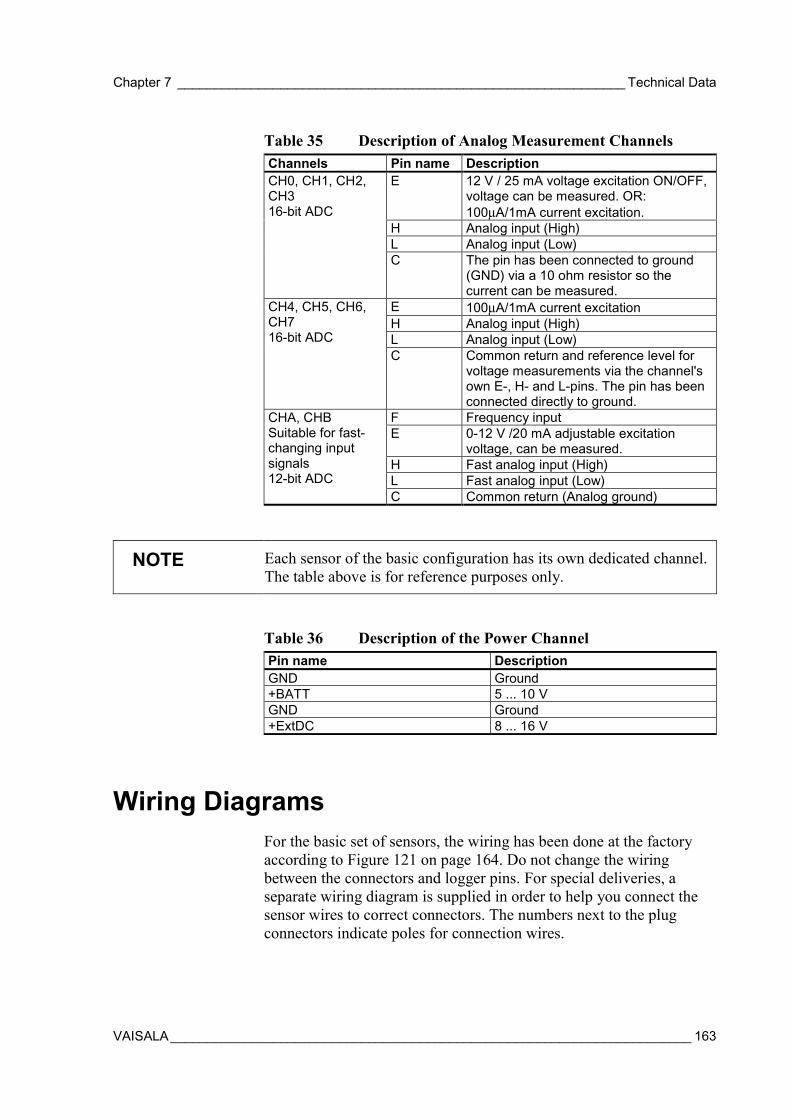
Chapter 7 _____________________________________________________________ Technical Data
VAISALA_______________________________________________________________________ 163
Table 35 Description of Analog Measurement ChannelsChannels Pin name Description
E 12 V / 25 mA voltage excitation ON/OFF,voltage can be measured. OR:100µA/1mA current excitation.
H Analog input (High)L Analog input (Low)
CH0, CH1, CH2,CH316-bit ADC
C The pin has been connected to ground(GND) via a 10 ohm resistor so thecurrent can be measured.
E 100µA/1mA current excitationH Analog input (High)L Analog input (Low)
CH4, CH5, CH6,CH716-bit ADC
C Common return and reference level forvoltage measurements via the channel'sown E-, H- and L-pins. The pin has beenconnected directly to ground.
F Frequency inputE 0-12 V /20 mA adjustable excitation
voltage, can be measured.H Fast analog input (High)L Fast analog input (Low)
CHA, CHBSuitable for fast-changing inputsignals12-bit ADC
C Common return (Analog ground)
NOTE Each sensor of the basic configuration has its own dedicated channel.The table above is for reference purposes only.
Table 36 Description of the Power ChannelPin name DescriptionGND Ground+BATT 5 ... 10 VGND Ground+ExtDC 8 ... 16 V
Wiring DiagramsFor the basic set of sensors, the wiring has been done at the factoryaccording to Figure 121 on page 164. Do not change the wiringbetween the connectors and logger pins. For special deliveries, aseparate wiring diagram is supplied in order to help you connect thesensor wires to correct connectors. The numbers next to the plugconnectors indicate poles for connection wires.

User's Guide _______________________________________________________________________
164 __________________________________________________________________ M210243en-A
9806-064
Figure 121 Basic Wiring Diagram
DSU232The DSU232 is an unisolated RS-232 module that will provide eithera double serial channel without handshaking or a single RS-232 withhandshaking. It can also feed 12 V (45 mA) for a serial sensor, whenused in sensor mode.
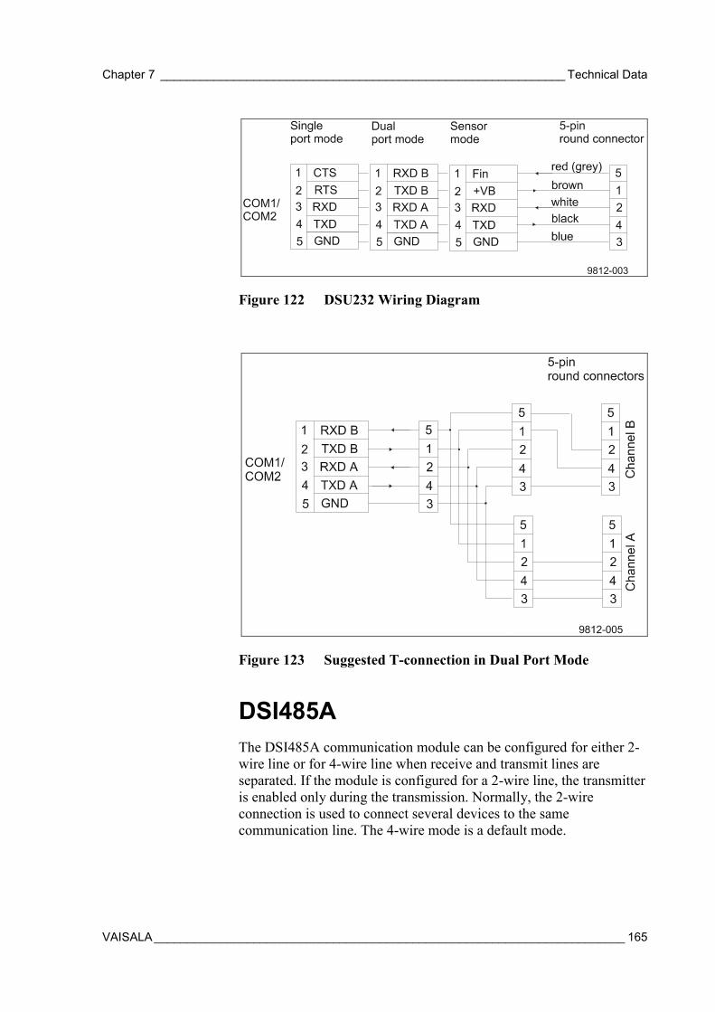
Chapter 7 _____________________________________________________________ Technical Data
VAISALA_______________________________________________________________________ 165
Figure 122 DSU232 Wiring Diagram
Figure 123 Suggested T-connection in Dual Port Mode
DSI485AThe DSI485A communication module can be configured for either 2-wire line or for 4-wire line when receive and transmit lines areseparated. If the module is configured for a 2-wire line, the transmitteris enabled only during the transmission. Normally, the 2-wireconnection is used to connect several devices to the samecommunication line. The 4-wire mode is a default mode.
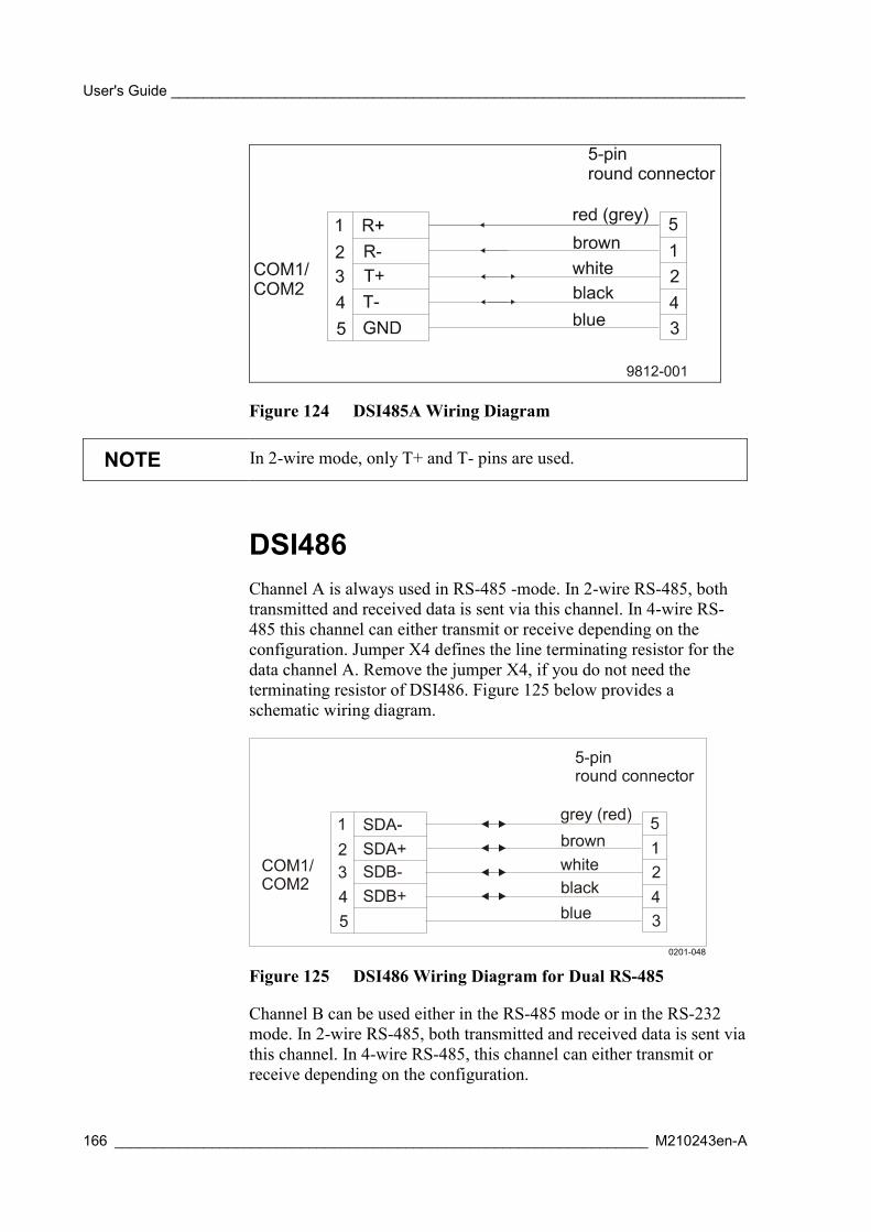
User's Guide _______________________________________________________________________
166 __________________________________________________________________ M210243en-A
Figure 124 DSI485A Wiring Diagram
NOTE In 2-wire mode, only T+ and T- pins are used.
DSI486Channel A is always used in RS-485 -mode. In 2-wire RS-485, bothtransmitted and received data is sent via this channel. In 4-wire RS-485 this channel can either transmit or receive depending on theconfiguration. Jumper X4 defines the line terminating resistor for thedata channel A. Remove the jumper X4, if you do not need theterminating resistor of DSI486. Figure 125 below provides aschematic wiring diagram.
0201-048
Figure 125 DSI486 Wiring Diagram for Dual RS-485
Channel B can be used either in the RS-485 mode or in the RS-232mode. In 2-wire RS-485, both transmitted and received data is sent viathis channel. In 4-wire RS-485, this channel can either transmit orreceive depending on the configuration.
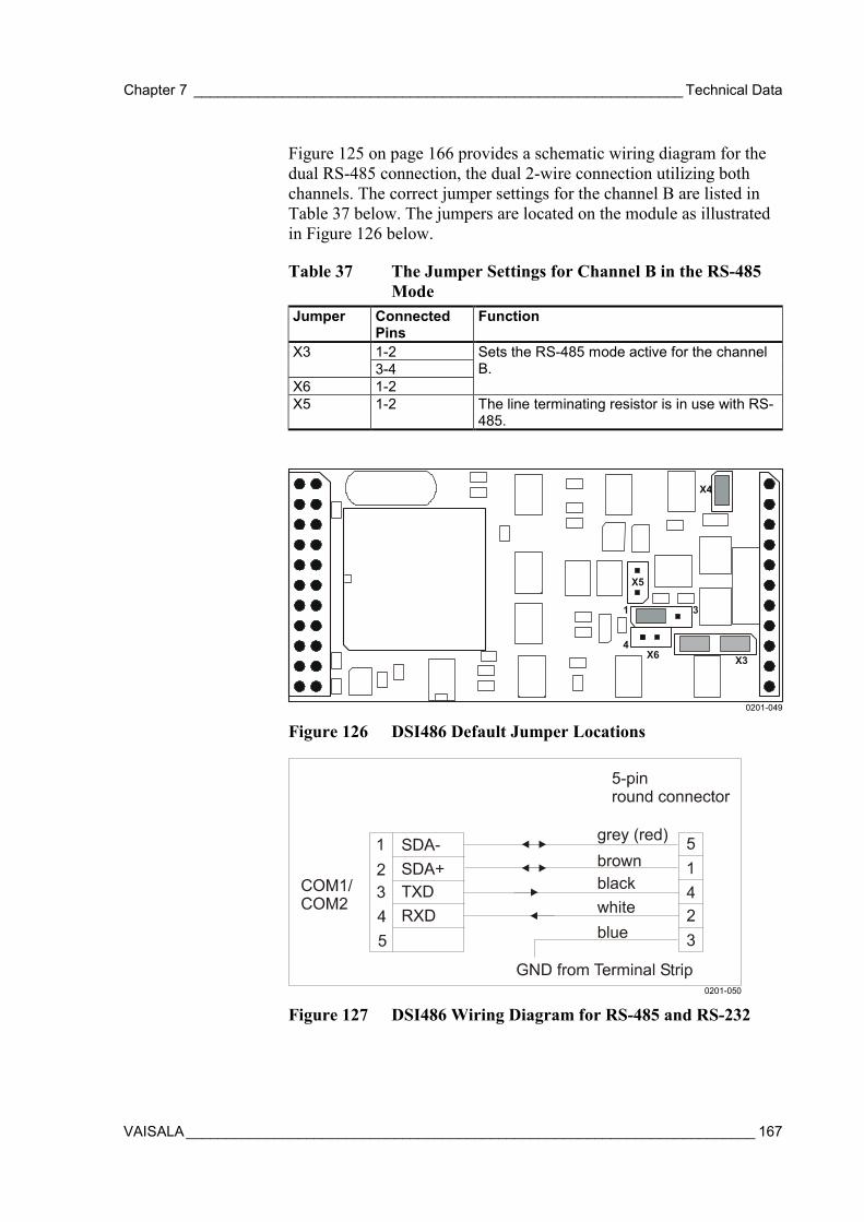
Chapter 7 _____________________________________________________________ Technical Data
VAISALA_______________________________________________________________________ 167
Figure 125 on page 166 provides a schematic wiring diagram for thedual RS-485 connection, the dual 2-wire connection utilizing bothchannels. The correct jumper settings for the channel B are listed inTable 37 below. The jumpers are located on the module as illustratedin Figure 126 below.
Table 37 The Jumper Settings for Channel B in the RS-485Mode
Jumper ConnectedPins
Function
1-2X33-4
X6 1-2
Sets the RS-485 mode active for the channelB.
X5 1-2 The line terminating resistor is in use with RS-485.
0201-049
Figure 126 DSI486 Default Jumper Locations
0201-050
Figure 127 DSI486 Wiring Diagram for RS-485 and RS-232
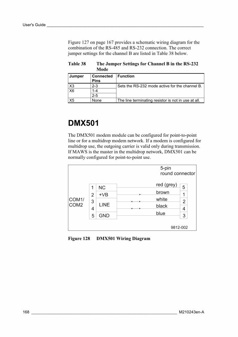
User's Guide _______________________________________________________________________
168 __________________________________________________________________ M210243en-A
Figure 127 on page 167 provides a schematic wiring diagram for thecombination of the RS-485 and RS-232 connection. The correctjumper settings for the channel B are listed in Table 38 below.
Table 38 The Jumper Settings for Channel B in the RS-232Mode
Jumper ConnectedPins
Function
X3 2-31-4X62-5
Sets the RS-232 mode active for the channel B.
X5 None The line terminating resistor is not in use at all.
DMX501The DMX501 modem module can be configured for point-to-pointline or for a multidrop modem network. If a modem is configured formultidrop use, the outgoing carrier is valid only during transmission.If MAWS is the master in the multidrop network, DMX501 can benormally configured for point-to-point use.
Figure 128 DMX501 Wiring Diagram

Chapter 7 _____________________________________________________________ Technical Data
VAISALA_______________________________________________________________________ 169
Connectors
QMT107Pin numbers in Table 39 below refer to Figure 129 below.
Table 39 Cable wire connectionsConnection Pin in Standard CableSignalColor Pin No
Connector L (CH2)default in MAWS
GND Blue 3 CLow out Black 4 L-VCC Brown 1 EHigh out White 2 H+
0106-035
Figure 129 Connector of QMT107 (Viewed from ConnectingSide)
VCC is a power supply from 6 to 30 VDC, which draws a maximumof 1.5 mA. This signal should be connected to the sensor excitationpin of the data logger. GND is common ground for VCC.
Pins High out and Low out, provide differential measurement signalsfrom the probe. These signals should be connected to the data logger'shigh impedance differential input (>1 MΩ).
Battery ChargingThe QML102 data logger has an internal battery charger circuitry thathas a programmable charging voltage of 4.5 to 9.9 V and fourselectable current limits 100 mA, 300 mA, 500 mA, and 700 mA.Charging voltage and charger input voltage (+ExtDC) can bemeasured with 1 % accuracy and charging current can be measured

User's Guide _______________________________________________________________________
170 __________________________________________________________________ M210243en-A
with 5 % accuracy. The charger is protected against reverse inputvoltage and temperature. In addition, it has internal reverse currentblocking to facilitate using solar cells without a blocking diode.
The MAWS charger is capable of handling 6 V lead batteries from 1.2Ah up to 24 Ah. Due to its limited current capability, it cannot quickcharge larger than 6 Ah batteries.
Power Supply and Battery Types
Battery Sensing
When QML102 first starts or resets, it tries to sense the battery typethat is connected to its internal battery connector (4-pin headerconnector at PCB near POWER connector). This connector has twosense pins that are used by charger software to automatically detectthe type of the connected battery.
External Power Supply
The external DC supply is always connected to POWER connectorpins +ExtDC and GND. The external power supply can be eitherregulated or unregulated DC supply (8 ... 30 V) or a solar cell ifinternal battery is present. To avoid excessive heating, 8 ... 16 V isrecommended.
The required current capability depends considerably on the MAWSconfiguration. If there are no optional sensors or other add-ons (radios,modems, etc.) that require constant powering and measurementintervals are long (1 minute or more for humidity, temperature, andpressure), even a few dozen milliamperes are enough to keep thesystem alive and slowly charge the battery. If there is no internalbattery, then at least 200 mA capability is recommended to avoidresetting due to possible current peaks. If the quickest possible batterycharging is required, then a 1A power supply is recommended.
NOTE The condition, when external DC supply is used without an internalbattery, is automatically detected. In this case, the charger sets itsoutput voltage to 9.9 V to enable maximum efficiency and minimumcurrent consumption from supplies of 12 VDC or higher.

Chapter 7 _____________________________________________________________ Technical Data
VAISALA_______________________________________________________________________ 171
Solar Cell
When the solar cell is used as an external power supply, a few thingsshould be kept in mind:
- Always use solar cell in combination with lead battery.
- To achieve the highest possible efficiency, a 6 to 8 V solar cell isrecommended.
NOTE You can use a 12 V solar cell, however, half of the delivered energyis lost as heat in the linear charger regulator.
Lead Batteries
The charger is capable of charging from 1.2 to 24 Ah, 6 V lead acidbatteries. There is room for one 1.2 Ah or 1.3 Ah battery in the loggerbattery compartment. If larger capacity is required, additional batteriesmust be connected to the POWER connector terminals GND and+BATT. Internal and external batteries can be present at the sametime; they are essentially paralleled. For protection, an automatic self-recovering fuse is used.
CAUTION The battery protection fuse may trip if internal and external batterieshave very different charge states when connecting them. This is dueto current flowing from one battery to the other. This conditionceases, when the battery voltages reach a balance after one or severaltrip-recover cycles.
To be able to efficiently charge the lead battery, the charger mustknow the total capacity of the connected lead batteries. This capacitysetting is done with the command:
battery [capacity]
Where capacity is the battery capacity in Ah. This value is also savedas a static parameter and is not lost if QML102 is reset or unpowered.
CAUTION If too large of a capacity value is used, the battery may bepermanently damaged due to excessive charge current.

User's Guide _______________________________________________________________________
172 __________________________________________________________________ M210243en-A
Primary Cells
Primary (non-rechargeable) cells from 6 to 9 V are most suitable foruse with QML102. The standard battery alternative for MAWS is adual cell lithium battery that has nominal voltage of 7.2 V, 35 Ahcapacity and a very wide temperature range. Common alkaline cells (4to 6 cells in series) in a suitable battery holder can be used as well.
These batteries do not generally fit into QML102 internal batterycompartment so they have to be connected to the POWER connectorterminals GND and +BATT.
NOTE Short pins 3 and 4 in QML102 internal battery connector with jumperor preferably use a special pin header for correct battery type sensing.
If the primary cell setting is detected, the charger circuitry of QML102is completely shut off to protect the battery from reverse currents.
CAUTION Never connect voltages higher than 10 V between terminals +BATTand GND as this may damage the QML102 electronics.
Lead Battery Charger OperationThe charger has three operating modes when a lead battery is detected:Normal Charge, Quick Charge and Float Charge. When MAWS starts,it first checks the battery type and if lead is found the charging taskstarts and is performed once a minute.
NOTE If the internal temperature of the QML102 is found to be below -20°C, the charging current is limited to 100 mA regardless of the batterycapacity.
Normal Charging
At first, the charging task always enters Normal Charging mode. InNormal Charge, charging voltage is set to 6.85 V corrected withtemperature coefficient. Charging current is set to 300 mA, 500 mA,or 700 mA depending on battery capacity.
Chapter 7 _____________________________________________________________ Technical Data
VAISALA_______________________________________________________________________ 173
If the battery is accepting certain amount of charging current and thereis enough energy available at +ExtDC input, the charging task entersQuick Charge mode. In the opposite case, when the charging currentdrops below 0.0075 CA even if more energy would be available, thecharging task enters Float Charge mode.
If the battery is discharging (charging current is negative), thecharging task always enters Normal Charge mode.
NOTE After powering up or reset, it takes several minutes to calculate theremaining capacity of the battery if the charger remains in NormalCharge mode.
Quick Charging
The purpose of the Quick Charge mode is to fill the battery as quicklyas possible using a specified quick charge voltage for lead batteries. InQuick Charge, charging voltage is set to 7.35 V corrected withtemperature coefficient. Charging current is typically the same or onestep higher as in Normal Charge mode.
NOTE Quick charging is not fully possible for batteries having more than 6Ah capacity, due to the limited maximum current of the QML102charger.
When the charging current drops below 0.075 CA, the charger taskenters Normal Charge mode. It also sets the remaining capacity to 90% if current dropping was caused by battery filling up rather thanmissing energy at +ExtDC terminal.
During Quick Charge, the remaining capacity can be reliablyestimated only after a certain amount of time. This is when thecharging voltage has reached the limit and the current has started todecrease. At this point, the remaining capacity is roughly 60 %.Normally, this point should be reached within two hours if the batterywas completely empty.
NOTE If an empty battery (with a voltage less than 5.5 V initially) startscharging and reaches the 60 % limit very quickly (or does not evenQuick Charge), it is probably damaged and should be replaced toensure reliable operation.

User's Guide _______________________________________________________________________
174 __________________________________________________________________ M210243en-A
Float Charging
When the charger task enters Float Charge mode, the battery isconsidered to be full and the remaining capacity is set to 100 %.Charging voltage is set to 6.85 V corrected with temperaturecoefficient. Current limit is always 100 mA in Float Charge.
If the battery starts to discharge, the charger task enters NormalCharge mode.
Temperature Protection
The charger protects lead batteries from extreme temperatures bylimiting the charge current or shutting the charger completely offunder certain conditions. This helps to prolong expected battery life.
If QML102 internal temperature rises higher than +50 °C, the chargershuts completely off and battery status shows "CHARGE_OFF". Notethat the battery manufacturers strictly forbid charging of their Leadbatteries above +50 °C.
When logger temperature drops below -20 °C, the charging current islimited to 100 mA to avoid unnecessary gas generation. Lead typebatteries do not accept charging energy well at low temperatures. Theylose the excess energy by generating gas. This may shorten batterylife. Normally, 100 mA limit should not cause any problems as theaverage current consumption of QML102 is much lower.
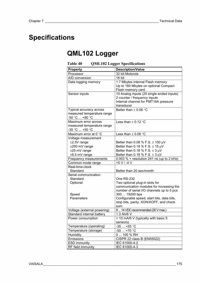
Chapter 7 _____________________________________________________________ Technical Data
VAISALA_______________________________________________________________________ 175
Specifications
QML102 LoggerTable 40 QML102 Logger SpecificationsProperty Description/ValueProcessor 32 bit MotorolaA/D conversion 16 bitData logging memory 1.7 Mbytes internal Flash memory
Up to 160 Mbytes on optional CompactFlash memory card.
Sensor inputs 10 Analog inputs (20 single ended inputs)2 counter / frequency inputsInternal channel for PMT16A pressuretransducer
Typical accuracy acrossmeasured temperature range-50 °C ... +80 °C
Better than ± 0.06 °C
Maximum error acrossmeasured temperature range-35 °C ... +50 °C
Less than ± 0.12 °C
Maximum error at 0 °C Less than ± 0.06 °CVoltage measurement ±2.5V range ±250 mV range ±25 mV range ±6.5 mV range
Better than 0.08 % F.S. ± 150 µVBetter than 0.18 % F.S. ± 15 µVBetter than 0.18 % F.S. ± 3 µVBetter than 0.18 % F.S. ± 3 µV
Frequency measurements 0.003 % + resolution 241 ns (up to 2 kHz)Common mode range +5 V / -4 VReal-time-clock Standard Better than 20 sec/monthSerial communication Standard Optional
Speed Parameters
One RS-232Two optional plug-in slots forcommunication modules for increasing thenumber of serial I/O channels up to 5 pcs300 ... 19200 bpsConfigurable speed, start bits, data bits,stop bits, parity, XON/XOFF, and checksum
Voltage (external powering) 8 ... 14 VDC recommended (30 V max.)Standard internal battery 1.3 Ah/6 VPower consumption < 10 mA/6 V (typically with basic 5
sensors)Temperature (operating) -35 ... +55 °CTemperature (storage) -50 ... +70 °CHumidity 0 ... 100 % RHEmissions CISPR 22 class B (EN55022)ESD immunity IEC 61000-4-2RF field immunity IEC 61000-4-3
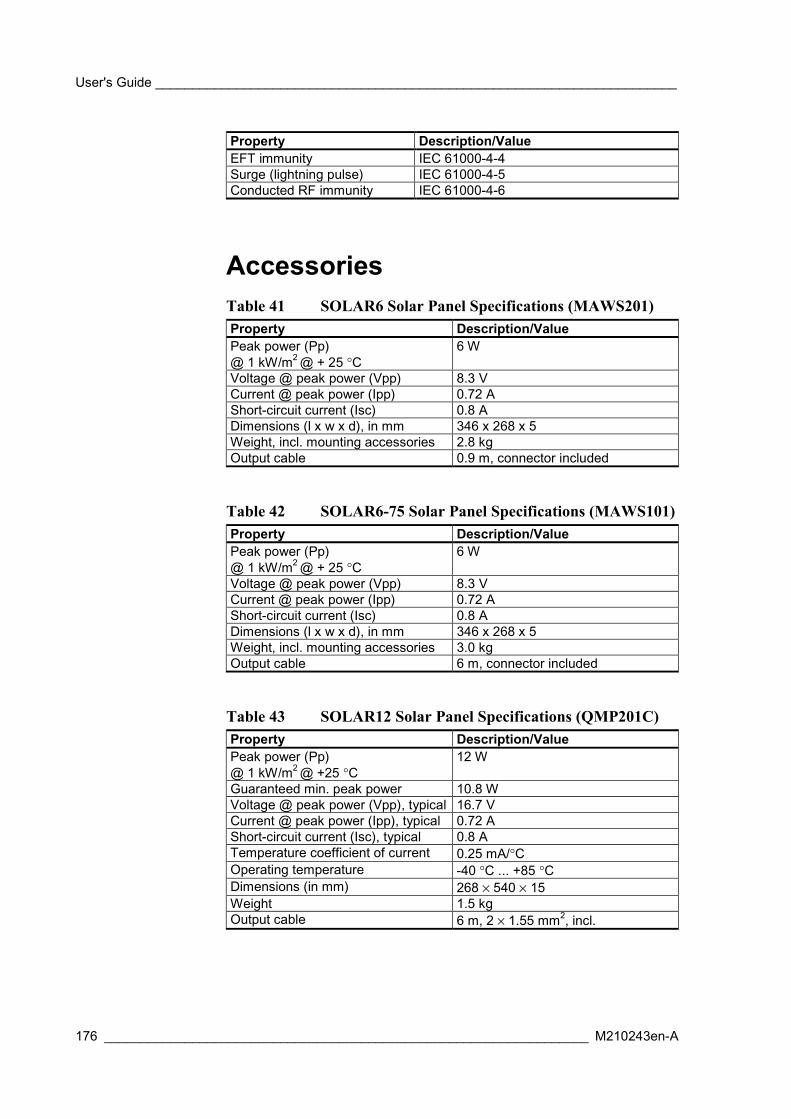
User's Guide _______________________________________________________________________
176 __________________________________________________________________ M210243en-A
Property Description/ValueEFT immunity IEC 61000-4-4Surge (lightning pulse) IEC 61000-4-5Conducted RF immunity IEC 61000-4-6
AccessoriesTable 41 SOLAR6 Solar Panel Specifications (MAWS201)Property Description/ValuePeak power (Pp)@ 1 kW/m2 @ + 25 °C
6 W
Voltage @ peak power (Vpp) 8.3 VCurrent @ peak power (Ipp) 0.72 AShort-circuit current (Isc) 0.8 ADimensions (l x w x d), in mm 346 x 268 x 5Weight, incl. mounting accessories 2.8 kgOutput cable 0.9 m, connector included
Table 42 SOLAR6-75 Solar Panel Specifications (MAWS101)Property Description/ValuePeak power (Pp)@ 1 kW/m2 @ + 25 °C
6 W
Voltage @ peak power (Vpp) 8.3 VCurrent @ peak power (Ipp) 0.72 AShort-circuit current (Isc) 0.8 ADimensions (l x w x d), in mm 346 x 268 x 5Weight, incl. mounting accessories 3.0 kgOutput cable 6 m, connector included
Table 43 SOLAR12 Solar Panel Specifications (QMP201C)Property Description/ValuePeak power (Pp)@ 1 kW/m2 @ +25 °C
12 W
Guaranteed min. peak power 10.8 WVoltage @ peak power (Vpp), typical 16.7 VCurrent @ peak power (Ipp), typical 0.72 AShort-circuit current (Isc), typical 0.8 ATemperature coefficient of current 0.25 mA/°COperating temperature -40 °C ... +85 °CDimensions (in mm) 268 × 540 × 15Weight 1.5 kgOutput cable 6 m, 2 × 1.55 mm2, incl.
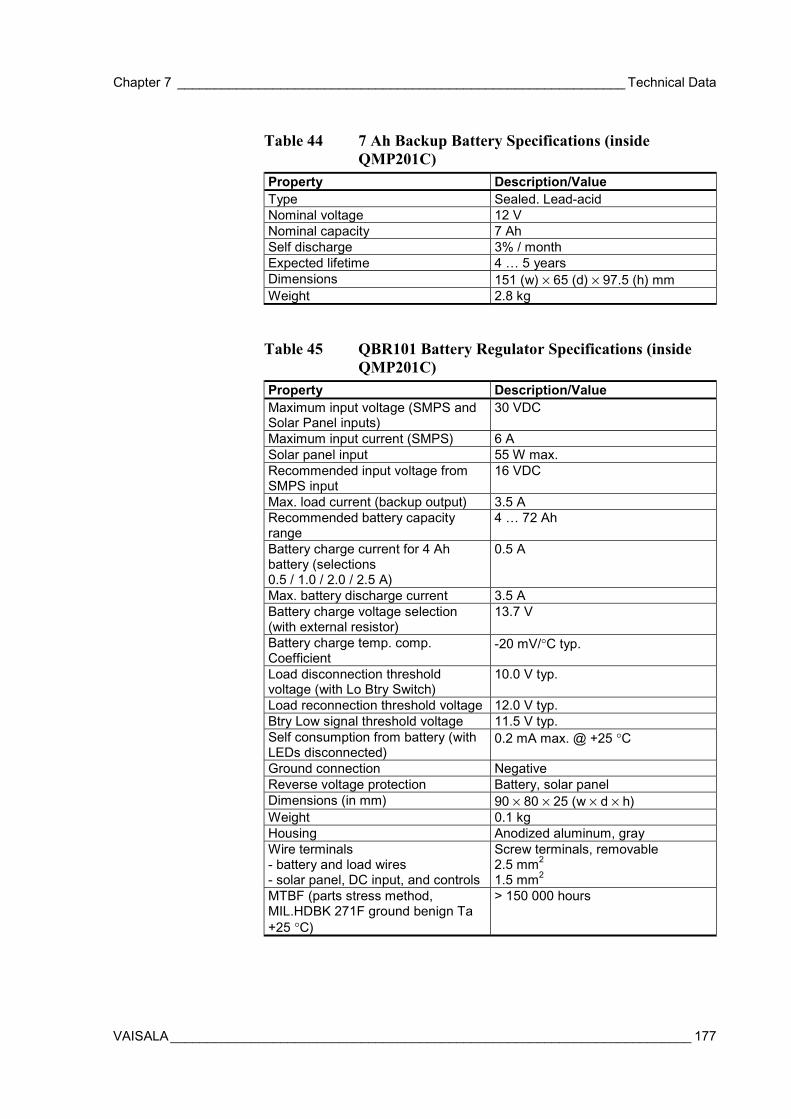
Chapter 7 _____________________________________________________________ Technical Data
VAISALA_______________________________________________________________________ 177
Table 44 7 Ah Backup Battery Specifications (insideQMP201C)
Property Description/ValueType Sealed. Lead-acidNominal voltage 12 VNominal capacity 7 AhSelf discharge 3% / monthExpected lifetime 4 … 5 yearsDimensions 151 (w) × 65 (d) × 97.5 (h) mmWeight 2.8 kg
Table 45 QBR101 Battery Regulator Specifications (insideQMP201C)
Property Description/ValueMaximum input voltage (SMPS andSolar Panel inputs)
30 VDC
Maximum input current (SMPS) 6 ASolar panel input 55 W max.Recommended input voltage fromSMPS input
16 VDC
Max. load current (backup output) 3.5 ARecommended battery capacityrange
4 … 72 Ah
Battery charge current for 4 Ahbattery (selections0.5 / 1.0 / 2.0 / 2.5 A)
0.5 A
Max. battery discharge current 3.5 ABattery charge voltage selection(with external resistor)
13.7 V
Battery charge temp. comp.Coefficient
-20 mV/°C typ.
Load disconnection thresholdvoltage (with Lo Btry Switch)
10.0 V typ.
Load reconnection threshold voltage 12.0 V typ.Btry Low signal threshold voltage 11.5 V typ.Self consumption from battery (withLEDs disconnected)
0.2 mA max. @ +25 °C
Ground connection NegativeReverse voltage protection Battery, solar panelDimensions (in mm) 90 × 80 × 25 (w × d × h)Weight 0.1 kgHousing Anodized aluminum, grayWire terminals- battery and load wires- solar panel, DC input, and controls
Screw terminals, removable2.5 mm2
1.5 mm2
MTBF (parts stress method,MIL.HDBK 271F ground benign Ta+25 °C)
> 150 000 hours

User's Guide _______________________________________________________________________
178 __________________________________________________________________ M210243en-A
Table 46 BWT15SX Mains Power Supply Unit Specifications(inside QMP201C)
Property Description/ValueOutput power 30 WOperating principle SMPSInput voltage range 85 … 264 VACFrequency range 47 … 440 HzInput current on full load: 110 VAC 220 VAC
0.6 A0.4 A
Output voltage +15 V, adjustable ± 10%Output current 2 AEfficiency 80 %Noise, ripple, and spikes ± 1 % + 50 mVp-p, max.Input regulation effect85 … 264 VAC
± 0.8 % max.
Load regulation effect0 … 2 A
± 0.9 % max.
Temperature coefficient ± 0.03 %/°COutput voltage rise time 200 ms max. at +25 °CHold-up time 20 ms min. at +25 °COver current protection Fold-back, automatic recoveringSwitching frequency(110V/230V)
50 kHz / 80 kHz
Electrical strength/ isolation: Input - Output Input - Chassis Output - Chassis Input - Output - Chassis resistance
3 kV AC, 1 minute2.5 kV AC, 1 minute500 V AC, 1 minute
50 MΩ minimumLeakage current 0.75 mA max.Operating temperature range -40 ... +60 °CWeight 250 g (chassis included)Approvals UL 1950
CSA 234 (IEC 950)VDE805EN 60959 (IEC 950)CE - EMC 89/336 EEC - LVD 73/23EEC
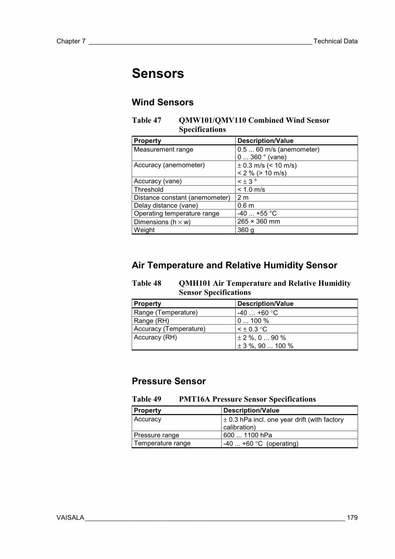
Chapter 7 _____________________________________________________________ Technical Data
VAISALA_______________________________________________________________________ 179
Sensors
Wind Sensors
Table 47 QMW101/QMV110 Combined Wind SensorSpecifications
Property Description/ValueMeasurement range 0.5 ... 60 m/s (anemometer)
0 ... 360 ° (vane)Accuracy (anemometer) ± 0.3 m/s (< 10 m/s)
< 2 % (> 10 m/s)Accuracy (vane) < ± 3 °Threshold < 1.0 m/sDistance constant (anemometer) 2 mDelay distance (vane) 0.6 mOperating temperature range -40 ... +55 °CDimensions (h × w) 265 × 360 mmWeight 360 g
Air Temperature and Relative Humidity Sensor
Table 48 QMH101 Air Temperature and Relative HumiditySensor Specifications
Property Description/ValueRange (Temperature) -40 … +60 °CRange (RH) 0 ... 100 %Accuracy (Temperature) < ± 0.3 °CAccuracy (RH) ± 2 %, 0 ... 90 %
± 3 %, 90 ... 100 %
Pressure Sensor
Table 49 PMT16A Pressure Sensor SpecificationsProperty Description/ValueAccuracy ± 0.3 hPa incl. one year drift (with factory
calibration)Pressure range 600 ... 1100 hPaTemperature range -40 ... +60 °C (operating)
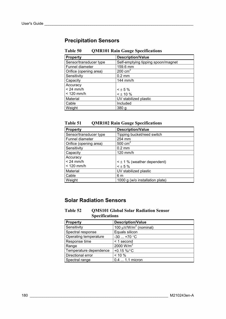
User's Guide _______________________________________________________________________
180 __________________________________________________________________ M210243en-A
Precipitation Sensors
Table 50 QMR101 Rain Gauge SpecificationsProperty Description/ValueSensor/transducer type Self-emptying tipping spoon/magnetFunnel diameter 159.6 mmOrifice (opening area) 200 cm2
Sensitivity 0.2 mmCapacity 144 mm/hAccuracy< 24 mm/h< 120 mm/h
< ± 5 %< ± 10 %
Material UV stabilized plasticCable IncludedWeight 380 g
Table 51 QMR102 Rain Gauge SpecificationsProperty Description/ValueSensor/transducer type Tipping bucket/reed switchFunnel diameter 254 mmOrifice (opening area) 500 cm2
Sensitivity 0.2 mmCapacity 120 mm/hAccuracy< 24 mm/h< 120 mm/h
< ± 1 % (weather dependent)< ± 5 %
Material UV stabilized plasticCable 6 mWeight 1000 g (w/o installation plate)
Solar Radiation Sensors
Table 52 QMS101 Global Solar Radiation SensorSpecifications
Property Description/ValueSensitivity 100 µV/W/m2 (nominal)Spectral response Equals siliconOperating temperature -30 ... +70 °CResponse time < 1 secondRange 2000 W/m2
Temperature dependence +0.15 %/°CDirectional error < 10 %Spectral range 0.4 ... 1.1 micron

Chapter 7 _____________________________________________________________ Technical Data
VAISALA_______________________________________________________________________ 181
Table 53 QMS102 Global Solar Radiation SensorSpecifications
Property Description/ValueMaximum irradiance 2000 W/m2
Spectral range 305 ... 2800 nm (50% points)Sensitivity 10 ... 35 µV/W/m2
Impedance 79 ... 200 ΩResponse time 18 seconds (95 %)Non-linearity ± 2.5 % (< 1000 W/m2)Temperature dependenceof sensitivity
6 % (-10 ... +40 °C)
Operating temperature -40 ... +80 °CZero-offset due totemperature changes
< 4 W/m2 @ 5 K/h temp. change
Tilt response < ± 2 %Signal output (atmosphericcondition)
0 ... 50 mV
Field of view 180°ISO class Second classCable length 10 m
Table 54 QMN101 Net Solar Radiation Sensor SpecificationsProperty Description/ValueSpectral response 0 ... 100 µmDetector protection Teflon coated (no domes)Sensitivity (upper detector) 10 µV/W/m2 (nominal)Recommended outputrange
-25 ... +25 mV
Sensor asymmetry 20 %Range -2000 ... +2000 W/m2
Response time (1/e) 20 s (nominal)Operating temperature - 30 ... + 70 °CDirectional error < 30 W/m2 (0 ... 60° @ 1000 W/m2)Stability < ± 2 % per yearNon-linearity < 1 % up to 2000 W/m2
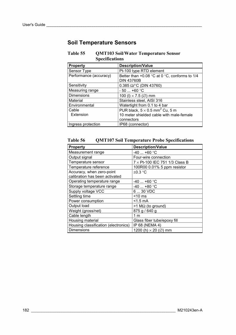
User's Guide _______________________________________________________________________
182 __________________________________________________________________ M210243en-A
Soil Temperature Sensors
Table 55 QMT103 Soil/Water Temperature SensorSpecifications
Property Description/ValueSensor Type Pt-100 type RTD elementPerformance (accuracy) Better than +0.08 °C at 0 °C, conforms to 1/4
DIN 43760BSensitivity 0.385 Ω/°C (DIN 43760)Measuring range - 50 ... +60 °CDimensions 100 (l) × 7.5 (∅) mmMaterial Stainless steel, AISI 316Environmental Watertight from 0.1 to 4 barCable Extension
PUR black, 5 × 0.5 mm2 Cu, 5 m10 meter shielded cable with male-femaleconnectors
Ingress protection IP68 (connector)
Table 56 QMT107 Soil Temperature Probe SpecificationsProperty Description/ValueMeasurement range -40 ... +60 °COutput signal Four-wire connectionTemperature sensor 7 × Pt-100 IEC 751 1/3 Class BTemperature reference 100R00 0.01% 5 ppm resistorAccuracy, when zero-pointcalibration has been activated
±0.3 °C
Operating temperature range -40 ... +60 °CStorage temperature range -40 ... +80 °CSupply voltage VCC 6 ... 30 VDCSettling time <10 msPower consumption <1.5 mAOutput load >1 MΩ (to ground)Weight (gross/net) 875 g / 640 gCable length 1 mHousing material Glass fiber tube/epoxy fillHousing classification (electronics) IP 68 (NEMA 4)Dimensions 1200 (h) × 20 (∅) mm
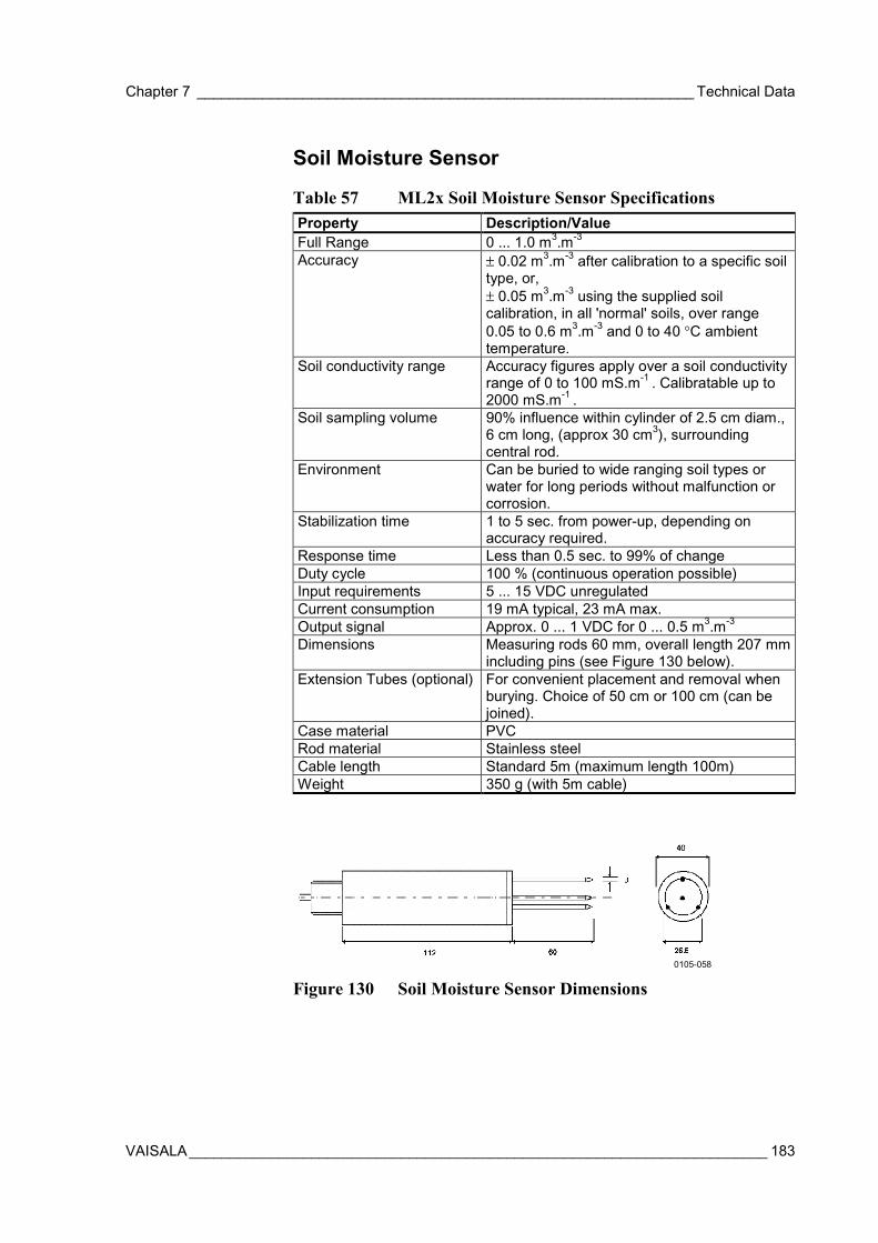
Chapter 7 _____________________________________________________________ Technical Data
VAISALA_______________________________________________________________________ 183
Soil Moisture Sensor
Table 57 ML2x Soil Moisture Sensor SpecificationsProperty Description/ValueFull Range 0 ... 1.0 m3.m-3
Accuracy ± 0.02 m3.m-3 after calibration to a specific soiltype, or,± 0.05 m3.m-3 using the supplied soilcalibration, in all 'normal' soils, over range0.05 to 0.6 m3.m-3 and 0 to 40 °C ambienttemperature.
Soil conductivity range Accuracy figures apply over a soil conductivityrange of 0 to 100 mS.m-1 . Calibratable up to2000 mS.m-1 .
Soil sampling volume 90% influence within cylinder of 2.5 cm diam.,6 cm long, (approx 30 cm3), surroundingcentral rod.
Environment Can be buried to wide ranging soil types orwater for long periods without malfunction orcorrosion.
Stabilization time 1 to 5 sec. from power-up, depending onaccuracy required.
Response time Less than 0.5 sec. to 99% of changeDuty cycle 100 % (continuous operation possible)Input requirements 5 ... 15 VDC unregulatedCurrent consumption 19 mA typical, 23 mA max.Output signal Approx. 0 ... 1 VDC for 0 ... 0.5 m3.m-3
Dimensions Measuring rods 60 mm, overall length 207 mmincluding pins (see Figure 130 below).
Extension Tubes (optional) For convenient placement and removal whenburying. Choice of 50 cm or 100 cm (can bejoined).
Case material PVCRod material Stainless steelCable length Standard 5m (maximum length 100m)Weight 350 g (with 5m cable)
0105-058
Figure 130 Soil Moisture Sensor Dimensions
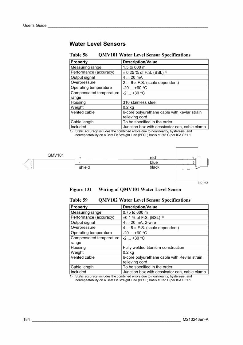
User's Guide _______________________________________________________________________
184 __________________________________________________________________ M210243en-A
Water Level Sensors
Table 58 QMV101 Water Level Sensor SpecificationsProperty Description/ValueMeasuring range 1.5 to 600 mPerformance (accuracy) ± 0.25 % of F.S. (BSL) 1)
Output signal 4 ... 20 mAOverpressure 2 ... 6 × F.S. (scale dependent)Operating temperature -20 ... +60 °CCompensated temperaturerange
-2 ... +30 °C
Housing 316 stainless steelWeight 0.2 kgVented cable 6-core polyurethane cable with kevlar strain
relieving cordCable length To be specified in the orderIncluded Junction box with dessicator can, cable clamp
1) Static accuracy includes the combined errors due to nonlinearity, hysteresis, andnonrepeatability on a Best Fit Straight Line (BFSL) basis at 25° C per ISA S51.1.
0101-008
Figure 131 Wiring of QMV101 Water Level Sensor
Table 59 QMV102 Water Level Sensor SpecificationsProperty Description/ValueMeasuring range 0.75 to 600 mPerformance (accuracy) ±0.1 % of F.S. (BSL) 1)
Output signal 4 ... 20 mA, 2-wireOverpressure 4 ... 8 × F.S. (scale dependent)Operating temperature -20 ... +60 °CCompensated temperaturerange
-2 ... +30 °C
Housing Fully welded titanium constructionWeight 0.2 kgVented cable 6-core polyurethane cable with Kevlar strain
relieving cordCable length To be specified in the orderIncluded Junction box with dessicator can, cable clamp
1) Static accuracy includes the combined errors due to nonlinearity, hysteresis, andnonrepeatability on a Best Fit Straight Line (BFSL) basis at 25° C per ISA S51.1.
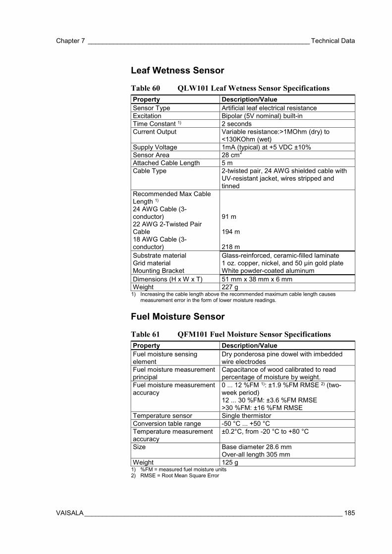
Chapter 7 _____________________________________________________________ Technical Data
VAISALA_______________________________________________________________________ 185
Leaf Wetness Sensor
Table 60 QLW101 Leaf Wetness Sensor SpecificationsProperty Description/ValueSensor Type Artificial leaf electrical resistanceExcitation Bipolar (5V nominal) built-inTime Constant 1) 2 secondsCurrent Output Variable resistance:>1MOhm (dry) to
<130KOhm (wet)Supply Voltage 1mA (typical) at +5 VDC ±10%Sensor Area 28 cm2
Attached Cable Length 5 mCable Type 2-twisted pair, 24 AWG shielded cable with
UV-resistant jacket, wires stripped andtinned
Recommended Max CableLength 1)
24 AWG Cable (3-conductor)22 AWG 2-Twisted PairCable18 AWG Cable (3-conductor)
91 m
194 m
218 mSubstrate materialGrid materialMounting Bracket
Glass-reinforced, ceramic-filled laminate1 oz. copper, nickel, and 50 µin gold plateWhite powder-coated aluminum
Dimensions (H x W x T) 51 mm x 38 mm x 6 mmWeight 227 g
1) Increasing the cable length above the recommended maximum cable length causesmeasurement error in the form of lower moisture readings.
Fuel Moisture Sensor
Table 61 QFM101 Fuel Moisture Sensor SpecificationsProperty Description/ValueFuel moisture sensingelement
Dry ponderosa pine dowel with imbeddedwire electrodes
Fuel moisture measurementprincipal
Capacitance of wood calibrated to readpercentage of moisture by weight.
Fuel moisture measurementaccuracy
0 ... 12 %FM 1): ±1.9 %FM RMSE 2) (two-week period)12 ... 30 %FM: ±3.6 %FM RMSE>30 %FM: ±16 %FM RMSE
Temperature sensor Single thermistorConversion table range -50 °C ... +50 °CTemperature measurementaccuracy
±0.2°C, from -20 °C to +80 °C
Size Base diameter 28.6 mmOver-all length 305 mm
Weight 125 g1) %FM = measured fuel moisture units2) RMSE = Root Mean Square Error
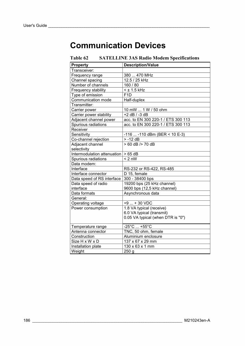
User's Guide _______________________________________________________________________
186 __________________________________________________________________ M210243en-A
Communication DevicesTable 62 SATELLINE 3AS Radio Modem SpecificationsProperty Description/ValueTransceiver:Frequency range 380 ... 470 MHzChannel spacing 12.5 / 25 kHzNumber of channels 160 / 80Frequency stability < ± 1.5 kHzType of emission F1DCommunication mode Half-duplexTransmitter:Carrier power 10 mW ... 1 W / 50 ohmCarrier power stability +2 dB / -3 dBAdjacent channel power acc. to EN 300 220-1 / ETS 300 113Spurious radiations acc. to EN 300 220-1 / ETS 300 113ReceiverSensitivity -116 ... -110 dBm (BER < 10 E-3)Co-channel rejection > -12 dBAdjacent channelselectivity
> 60 dB /> 70 dB
Intermodulation attenuation > 65 dBSpurious radiations < 2 nWData modem:Interface RS-232 or RS-422, RS-485Interface connector D 15, femaleData speed of RS interface 300 - 38400 bpsData speed of radiointerface
19200 bps (25 kHz channel)9600 bps (12,5 kHz channel)
Data formats Asynchronous dataGeneral:Operating voltage +9 ... + 30 VDCPower consumption 1.8 VA typical (receive)
6.0 VA typical (transmit)0.05 VA typical (when DTR is "0")
Temperature range -25°C ... +55°CAntenna connector TNC, 50 ohm, femaleConstruction Aluminium enclosureSize H x W x D 137 x 67 x 29 mmInstallation plate 130 x 63 x 1 mmWeight 250 g
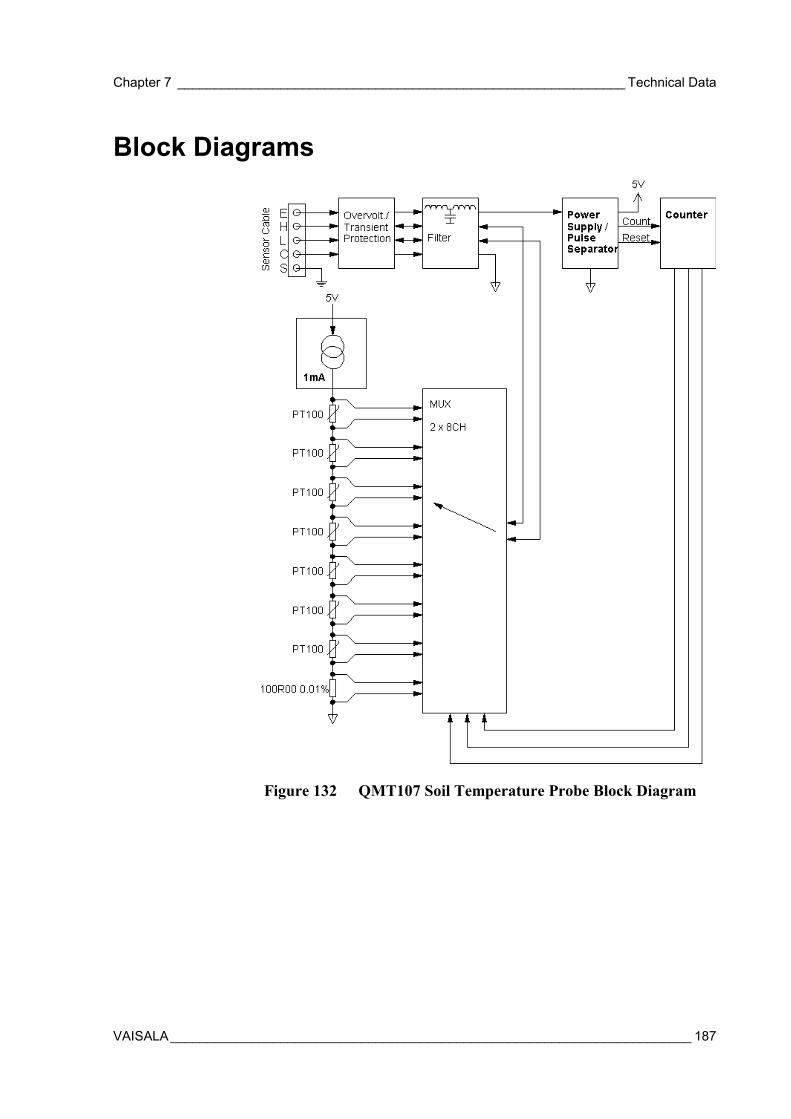
Chapter 7 _____________________________________________________________ Technical Data
VAISALA_______________________________________________________________________ 187
Block Diagrams
Figure 132 QMT107 Soil Temperature Probe Block Diagram

User's Guide _______________________________________________________________________
188 __________________________________________________________________ M210243en-A
This page intentionally left blank.

Appendix A _________________________________________________________________ Glossary
VAISALA_______________________________________________________________________ 189
APPENDIX A
GLOSSARY
This glossary includes:
- Explanations of some general meteorological terms
- Explanations of some general technical terms
- Descriptions of MAWS components and concepts
- Explanations of the terms used in MAWS specifications.
User's Guide _______________________________________________________________________
190 __________________________________________________________________ M210243en-A
Accuracy The degree of conformity of a measured or calculated value to itsactual or specified value.
Altitude The station altitude in meters from sea level.
Atmosphericpressure
The pressure at a given point due to the gravitational force on thecolumn of air above it. The official unit of pressure is Pascal(Pa = newton/m2). The unit hectopascal (hPa) has been chosen to beused in meteorological barometric pressure measurement.1 hPa = 100 Pa = 1 mbar
Barometer Instrument for measuring atmospheric pressure.
Barometricpressure
See Atmospheric pressure.
Baud The unit of signaling speed of a line, which is the number oftransitions (voltage or frequency changes) that are made per second.The term has often been erroneously used to specify bits per second.However, only at very low speeds is baud equal to bps; for example,300 baud is the same as 300 bps. Beyond that, one baud can be madeto represent more than one bit. For example, a V.22bis modemgenerates 1200 bps at 600 baud.
Celsius scale Temperature scale having the freezing point of pure water at 0 °Cand the boiling point at 100 °C under standard sea level pressure. Allthe temperatures measured with MAWS are given in Celsiusdegrees.
Configuration Set of instructions for the MAWS logger. The compiledconfiguration (a script) is in fact a program that runs in MAWS.
Crosswind The wind blowing perpendicular to the course of a moving object.
Damping ratio Describes the response of a wind vane to a sudden change in winddirection. It is defined as the ratio of the actual damping to thecritical damping. Critical damping is that value of damping whichgives the fastest transient response without overshoot.
Delay distance The passage of air necessary over a wind vane to cause the vane torespond to 50 % of a step function change in wind direction.
Appendix A _________________________________________________________________ Glossary
VAISALA_______________________________________________________________________ 191
The temperature at which the air, if cooled, would reach saturation,and at which dew would therefore begin to condense out on a solidsurface. The TD is calculated using the following formula:
15.273b
2ac
bcTD −+×
×=
where
a =RH100ln
b = 2711.5TA2.1a15.0 +×−×c = TA + 273.15TA = Actual air temperature [°C] measured by MAWS
Dew point(temperature)
RH = Actual relative humidity [%] measured by MAWS
DSI485A Serial RS-485 communication module for MAWS.
DSU232 Serial RS-232 communication module for MAWS.
Global radiation The total of direct solar radiation and diffuse sky radiation receivedby a horizontal surface. Global radiation is measured bypyranometers.
Gust The peak momentary wind velocity within a given interval of time,for example, 10 minutes. (Vmax-Vmin)/Vmean.
Hexadecimal Numbering system using the base number 16 and including the tendecimal digits (0 to 9) along with six alpha digits (A to F).
Humidity The water vapor content of the air. Weather station sensorscommonly measure relative humidity. Relative humidity is the ratioof water vapor pressure present in a gas (Pw) to the maximumpressure of water vapor that could be present in the gas in thattemperature [Pws(t)].%RH = 100 x Pw / Pws (t)
LED Light Emitting Diode
Logger The processing unit of the MAWS weather station. The electronicsof the logger take care of measuring, storing, and processing of themeasured quantities.
Logging The process of storing the measured and calculated values in thelogger's memory.
User's Guide _______________________________________________________________________
192 __________________________________________________________________ M210243en-A
Lull The minimum of wind speed during a certain time interval (asdefined in the wind calculation module of MAWS).
Modem A device that allows a terminal or computer at one location tocommunicate with a terminal or computer at a distant location viawire or telephone lines.
Precipitation Term that refers to all forms of water particles that fall upon theearth. This includes rain, snow, and hail. It is the universal practiceto distinguish between rain, snow, and total precipitation. Snow issometimes measured as such and sometimes it is melted andmeasured as water.
Pslevel The pressure sensor level in meters from the station altitude.
Pyranometer An instrument that measures solar energy received from the entirehemisphere (180 degrees field of view). The output is expressed inWatts per square meter (W/m2).
The actual atmospheric pressure at the level of station altitude or atthe height of the runway threshold. The difference of the pressuresensor level and the station altitude (or runway threshold) isindicated by the pressure sensor (pslevel) setting in MAWS. QFE isnormally used for aviation purposes. QFE is calculated using thefollowing formula:
QFE PA eHS
7996 b HS 29.33 TA= ⋅ + ⋅ + ⋅
where
PA = Station pressure measured by MAWS [hPa]HS = The height of the pressure sensor from the station level or
from the runway threshold level [m], set by the pslevelcommand
b = 0.0086 °C/m
QFE
TA = Actual air temperature [°C] measured by MAWS
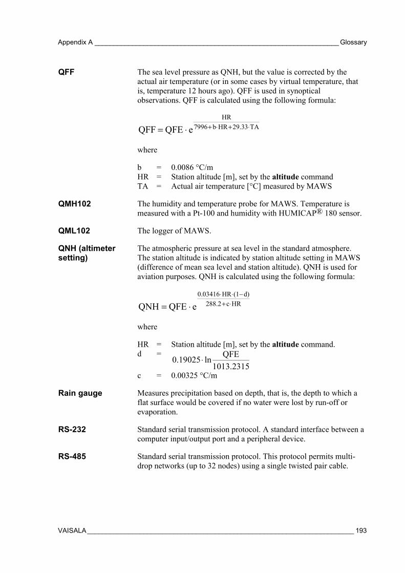
Appendix A _________________________________________________________________ Glossary
VAISALA_______________________________________________________________________ 193
The sea level pressure as QNH, but the value is corrected by theactual air temperature (or in some cases by virtual temperature, thatis, temperature 12 hours ago). QFF is used in synopticalobservations. QFF is calculated using the following formula:
QFF QFE eHR
7996 b HR 29.33 TA= ⋅ + ⋅ + ⋅
where
b = 0.0086 °C/mHR = Station altitude [m], set by the altitude command
QFF
TA = Actual air temperature [°C] measured by MAWS
QMH102 The humidity and temperature probe for MAWS. Temperature ismeasured with a Pt-100 and humidity with HUMICAP® 180 sensor.
QML102 The logger of MAWS.
The atmospheric pressure at sea level in the standard atmosphere.The station altitude is indicated by station altitude setting in MAWS(difference of mean sea level and station altitude). QNH is used foraviation purposes. QNH is calculated using the following formula:
QNH QFE e0.03416 HR (1 d)
288.2 c HR= ⋅⋅ ⋅ −+ ⋅
where
HR = Station altitude [m], set by the altitude command.d =
0.19025 ln QFE1013.2315
⋅
QNH (altimetersetting)
c = 0.00325 °C/m
Rain gauge Measures precipitation based on depth, that is, the depth to which aflat surface would be covered if no water were lost by run-off orevaporation.
RS-232 Standard serial transmission protocol. A standard interface between acomputer input/output port and a peripheral device.
RS-485 Standard serial transmission protocol. This protocol permits multi-drop networks (up to 32 nodes) using a single twisted pair cable.

User's Guide _______________________________________________________________________
194 __________________________________________________________________ M210243en-A
Solar radiation The solar energy received from the entire hemisphere. It is measuredwith a pyranometer.
Synchronizingtime
Ties the operation to the clock for software operations. For instance,if an operation is always to be performed twenty minutes to the hour,the synchronizing time should be set to 00:40:00.
WMO The World Meteorological Organization.
ZModem File transfer protocol that is used when transferring files betweenMAWS and a terminal program.