automatic transmission
TRANSCRIPT
AT07I-05
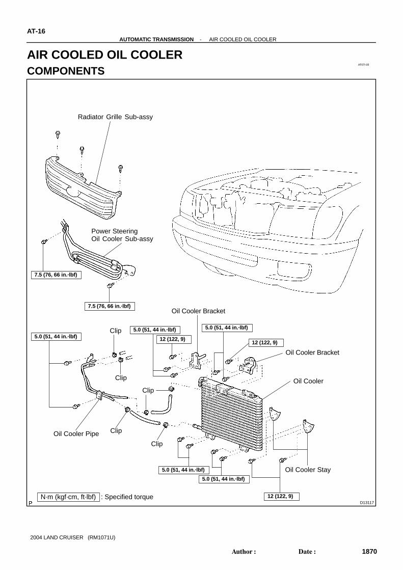
D13117N·m (kgf·cm, ft·lbf) : Specified torque
Clip
Oil Cooler Pipe
Clip
Clip
Clip
Clip
Oil Cooler Stay
Oil Cooler
12 (122, 9)
Oil Cooler Bracket
Radiator Grille Sub-assy
7.5 (76, 66 in.·lbf)
7.5 (76, 66 in.·lbf)
Power SteeringOil Cooler Sub-assy
Oil Cooler Bracket
5.0 (51, 44 in.·lbf)5.0 (51, 44 in.·lbf) 5.0 (51, 44 in.·lbf)
5.0 (51, 44 in.·lbf)
5.0 (51, 44 in.·lbf)
12 (122, 9)
12 (122, 9)
AT-16-AUTOMATIC TRANSMISSION AIR COOLED OIL COOLER
1870Author: Date:
2004 LAND CRUISER (RM1071U)
AIR COOLED OIL COOLERCOMPONENTS

AT07K-05
-AUTOMATIC TRANSMISSION AIR COOLED OIL COOLERAT-19
1873Author: Date:
INSTALLATIONInstallation is in the reverse order of removal (See page AT-17 ).HINT:After installtion, check fluid level (See page AT-3-1 ).
AT113-01
D12665
D01688
D01689
D01690
-AUTOMATIC TRANSMISSION AIR COOLED OIL COOLERAT-17
1871Author: Date:
2004 LAND CRUISER (RM1071U)
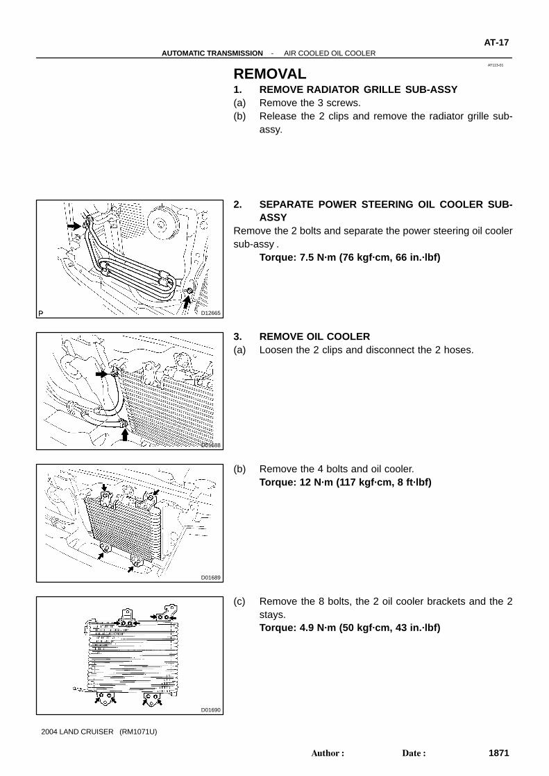
REMOVAL1. REMOVE RADIATOR GRILLE SUB-ASSY(a) Remove the 3 screws.(b) Release the 2 clips and remove the radiator grille sub-
assy.
2. SEPARATE POWER STEERING OIL COOLER SUB-ASSY
Remove the 2 bolts and separate the power steering oil coolersub-assy .
Torque: 7.5 N·m (76 kgf·cm, 66 in.·lbf)
3. REMOVE OIL COOLER(a) Loosen the 2 clips and disconnect the 2 hoses.
(b) Remove the 4 bolts and oil cooler.Torque: 12 N·m (117 kgf·cm, 8 ft·lbf)
(c) Remove the 8 bolts, the 2 oil cooler brackets and the 2stays.Torque: 4.9 N·m (50 kgf·cm, 43 in.·lbf)

D12666
D01692
AT-18-AUTOMATIC TRANSMISSION AIR COOLED OIL COOLER
1872Author: Date:
2004 LAND CRUISER (RM1071U)
4. REMOVE OIL COOLER PIPE BRACKET(a) Loosen the 2 clips and disconnect the 2 hoses.
(b) Remove the 2 bolts and the oil cooler pipe bracket.Torque: 4.9 N·m (50 kgf·cm, 43 in.·lbf)
(c) Loosen the 2 clips and disconnect the 2 hoses.
AT10Z-02
D12704
A
B
Orange
Blue
D12739
D12704
A
B
Orange
Blue
AT-6-AUTOMATIC TRANSMISSION ATF TEMPERATURE SENSOR
1860Author: Date:
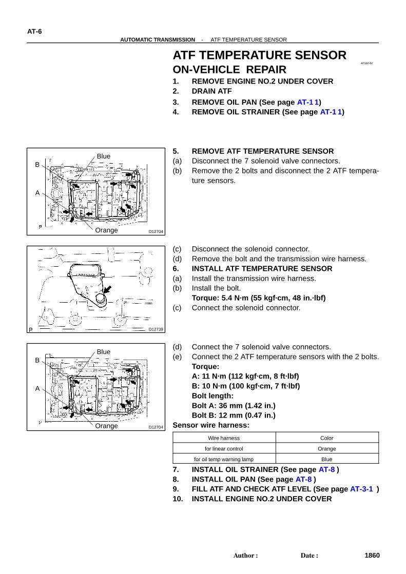
ATF TEMPERATURE SENSORON-VEHICLE REPAIR1. REMOVE ENGINE NO.2 UNDER COVER2. DRAIN ATF3. REMOVE OIL PAN (See page AT-1 1)4. REMOVE OIL STRAINER (See page AT-1 1)
5. REMOVE ATF TEMPERATURE SENSOR(a) Disconnect the 7 solenoid valve connectors.(b) Remove the 2 bolts and disconnect the 2 ATF tempera-
ture sensors.
(c) Disconnect the solenoid connector.(d) Remove the bolt and the transmission wire harness.6. INSTALL ATF TEMPERATURE SENSOR(a) Install the transmission wire harness.(b) Install the bolt.
Torque: 5.4 N·m (55 kgf·cm, 48 in.·lbf)(c) Connect the solenoid connector.
(d) Connect the 7 solenoid valve connectors.(e) Connect the 2 ATF temperature sensors with the 2 bolts.
Torque:A: 11 N·m (112 kgf·cm, 8 ft·lbf)B: 10 N·m (100 kgf·cm, 7 ft·lbf)Bolt length:Bolt A: 36 mm (1.42 in.)Bolt B: 12 mm (0.47 in.)
Sensor wire harness:
Wire harness Color
for linear control Orange
for oil temp warning lamp Blue
7. INSTALL OIL STRAINER (See page AT-8 )8. INSTALL OIL PAN (See page AT-8 )9. FILL ATF AND CHECK ATF LEVEL (See page AT-3-1 )10. INSTALL ENGINE NO.2 UNDER COVER

AT07M-02
D12728
Clutch No.2 (C2)
Clutch No.3 (C3)
Clutch No.1 (C1)One-way ClutchNo.1 (F1)
One-way ClutchNo.2 (F2)
Brake No.3(B3)
Brake No.1 (B1)
Brake No.2 (B2) One-way ClutchNo.3 (F3)
Brake No.4 (B4)
Shift Solenoid Valve SLT
Shift Solenoid Valve SL1
Shift Solenoid Valve S1
Shift Solenoid Valve S2
Shift Solenoid Valve SRShift Solenoid Valve SL2
Shift Solenoid Valve SLU
AT-2-AUTOMATIC TRANSMISSION AUTOMATIC TRANSMISSION SYSTEM
1853Author: Date:
2004 LAND CRUISER (RM1071U)
OPERATION

SL1
ParkReverseNeutral
1st2nd
4th5th1st
4th1st
3rd1st
1st
S1 C1 C2 B1 B2 B3 B4 F3F1 F2
: Operating
GearPosition
Shift LeverPosition
2nd
2nd
2nd
3rd
3rd
RN
D
4
3
2
L
P
S2 SR SL2 C3SLU
xxx
xx
x
xxxx
xxx
xx
x
x
xxxxxxx
xxxxxxxx
x
xxxxxxx
x
xxx
xxxxxx
x
x
xx
xxxxxx
xxx
xxxxxx
xxx
x
xxxxxx
xx
xxxxxx
x
xxx
xx
xx
xxx
x
xxxxx
xxxxxx
xxx
xxxxxxxxxxxxxx
x
x
xxxx
x
x
xx
x
x
xxxxxxxxxxxx
xx
xx
x
xx
xxx
xx
x x xxxx
xx
xxxx
xxxx
xxx
xxx
xx
xx
xx
F1, F2, F3 : Operate only when driving
x
-AUTOMATIC TRANSMISSION AUTOMATIC TRANSMISSION SYSTEMAT-3
1854Author: Date:
2004 LAND CRUISER (RM1071U)
AT147-03
D13650
Refill Plug
Overflow Plug
D14352
Overflow Tube
AT-3-1-AUTOMATIC TRANSMISSION AUTOMATIC TRANSMISSION SYSTEM
1855Author: Date:
2004 LAND CRUISER (RM1071U)
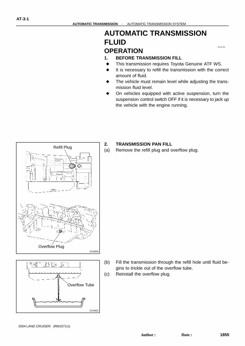
AUTOMATIC TRANSMISSIONFLUIDOPERATION1. BEFORE TRANSMISSION FILL This transmission requires Toyota Genuine ATF WS. It is necessary to refill the transmission with the correct
amount of fluid. The vehicle must remain level while adjusting the trans-
mission fluid level. On vehicles equipped with active suspension, turn the
suspension control switch OFF if it is necessary to jack upthe vehicle with the engine running.
2. TRANSMISSION PAN FILL(a) Remove the refill plug and overflow plug.
(b) Fill the transmission through the refill hole until fluid be-gins to trickle out of the overflow tube.
(c) Reinstall the overflow plug.
A04550
9 10 11 12 13 1415 16
1 2 3 4 5 6 7 8
DLC3
CG
TC
-AUTOMATIC TRANSMISSION AUTOMATIC TRANSMISSION SYSTEMAT-3-2
1856Author: Date:
2004 LAND CRUISER (RM1071U)
3. TRANSMISSION FILL(a) Fill the transmission with the correct amount of fluid as
listed in the table below.(b) Reinstall the refill plug to avoid fluid splash.
Repair Fill Amount
Transmission pan and drain plug remov-
al1.3 liters (1.37 US qts, 1.14 Imp. qts)
Transmission valve body removal 3.9 liters (4.12 US qts, 3.43 Imp. qts)
Torque converter removal 5.3 liters (5.60 US qts, 4.66 Imp. qts)
Entire transmission assembly 5.3 liters (5.60 US qts, 4.66 Imp. qts)
HINT:If you cannot add the listed amount of fluid, do the following:
(1) Install the refill plug.(2) Allow the engine to idle with air conditioning OFF.(3) Move the shift lever through entire gear range to cir-
culate fluid.(4) Wait for 30 seconds with the engine idling.(5) Stop the engine.(6) Remove the refill plug and add fluid.(7) Reinstall the refill plug.
4. FLUID CIRCULATION(a) Allow the engine to idle with the air conditioning OFF.(b) Move the shift lever through entire gear range to circulate
fluid.
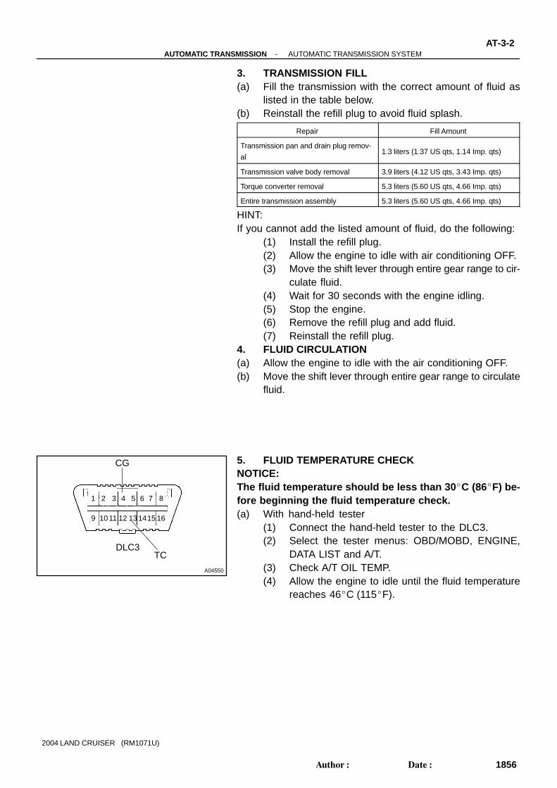
5. FLUID TEMPERATURE CHECKNOTICE:The fluid temperature should be less than 30 C (86F) be-fore beginning the fluid temperature check.(a) With hand-held tester
(1) Connect the hand-held tester to the DLC3.(2) Select the tester menus: OBD/MOBD, ENGINE,
DATA LIST and A/T.(3) Check A/T OIL TEMP.(4) Allow the engine to idle until the fluid temperature
reaches 46C (115F).
D14352
Overflow Tube
AT-3-3-AUTOMATIC TRANSMISSION AUTOMATIC TRANSMISSION SYSTEM
1857Author: Date:
2004 LAND CRUISER (RM1071U)
(b) Without hand-held tester (Using A/T OIL TEMP indicator)(1) Connect terminals between CG (4) and TC (13) of
the DLC3 using SST (09843-18040).(2) Move the shift lever back and forth between N and
D at 1.5 seconds interval for six seconds.(3) The D shift indicator on the combination meter
comes on for two seconds. This indicates that thefluid temperature check mode has been started.
(4) The D shift indicator comes on again when the fluidtemperature reaches 46C (115F) and blinkswhen it exceeds 56C (130F).
(5) Allow the engine to idle until the fluid temperaturereaches 46C (115F).
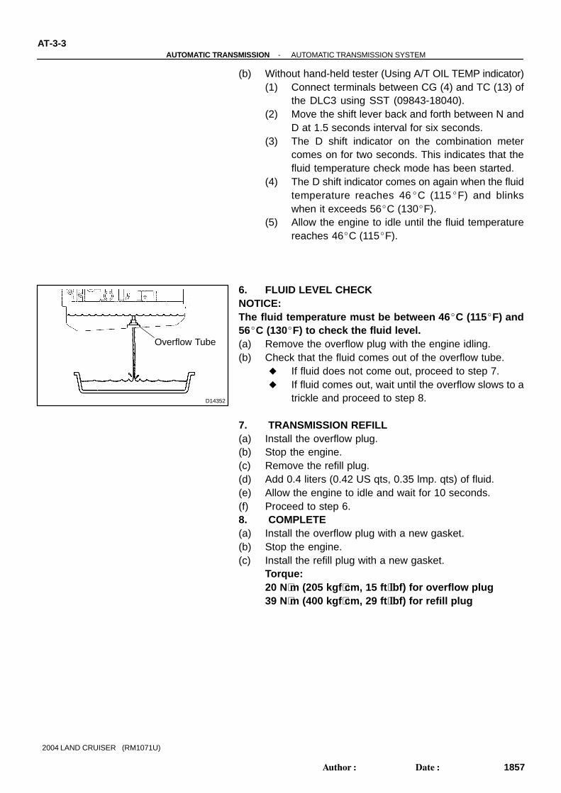
6. FLUID LEVEL CHECKNOTICE:The fluid temperature must be between 46C (115F) and56C (130F) to check the fluid level.(a) Remove the overflow plug with the engine idling.(b) Check that the fluid comes out of the overflow tube.
If fluid does not come out, proceed to step 7. If fluid comes out, wait until the overflow slows to a
trickle and proceed to step 8.
7. TRANSMISSION REFILL(a) Install the overflow plug.(b) Stop the engine.(c) Remove the refill plug.(d) Add 0.4 liters (0.42 US qts, 0.35 lmp. qts) of fluid.(e) Allow the engine to idle and wait for 10 seconds.(f) Proceed to step 6.8. COMPLETE(a) Install the overflow plug with a new gasket.(b) Stop the engine.(c) Install the refill plug with a new gasket.
Torque: 20 N⋅m (205 kgf ⋅cm, 15 ft ⋅lbf) for overflow plug39 N⋅m (400 kgf ⋅cm, 29 ft ⋅lbf) for refill plug

AT07L-02
-AUTOMATIC TRANSMISSION AUTOMATIC TRANSMISSION SYSTEMAT-1
1852Author: Date:
2004 LAND CRUISER (RM1071U)
AUTOMATIC TRANSMISSION SYSTEMPRECAUTIONIf the vehicle is equipped with a mobile communication system, refer to the precautions in the IN section.

AT080-04
D13664
Air Cleaner Cap
Radiator Reservoir
Fan and FluidCoupling Assembly
Fan Shroud
x6
x4
80 (820, 59)
80 (820, 59)
80 (820, 59)
80 (820, 59)
Front Propeller Shaft
48 (490, 35)
Hole Plug
18 (185, 13)
Torque ConverterClutch
50 (510, 37)
74 (750, 54)
50 (510, 37)
N·m (kgf·cm, ft·lbf) : Specified torque Non-reusable part
Transfer Case Protector
Engine MoutingInsulator RR
x4
x6
37 (377, 27)
71 (724, 52)
LH Front Exhaust Pipe
Transmissionwith Transfer
106 (1,080, 78)
106 (1,080, 78)
106 (1,080, 78)
GroundCable
TransmissionShift Control Rod
Pin
Rear Propeller Shaft
RH Front Exhaust Pipe
Transfer ShiftLever Boot
Upper Console Panel
Transfer Shift Lever Knob
5.4 (55, 48 in.·lbf)
Clip
Transfer ShiftLever
Engine No. 1Under Cover
Crossmember
12 (122, 9)
59 (600, 43)
29 (296, 21)
Engine No. 2Under Cover
20 (204, 15)
34 (347, 25)Oil Cooler Pipe
29 (296, 21) 29 (296, 21)
-AUTOMATIC TRANSMISSION AUTOMATIC TRANSMISSION UNITAT-29
1883Author: Date:
2004 LAND CRUISER (RM1071U)
AUTOMATIC TRANSMISSION UNITCOMPONENTS

D01624
AT082-06
-AUTOMATIC TRANSMISSION AUTOMATIC TRANSMISSION UNITAT-33
1887Author: Date:
INSTALLATION1. CHECK TORQUE CONVERTER CLUTCH INSTALLA-
TIONUsing calipers and a straight edge, measure the distance fromthe installed surface of the transmission housing to the installedsurface of the torque converter clutch.
Correct distance: More than 17.1 mm (0.673 in.)2. TRANSMISSION INSTALLATIONInstallation is in the reverse order of removal(See page AT-33 ).HINT: Transmission control rod and the park/neutral position
switch (See page DI-361 ) ATF level (See page AT-3-1 ) Conduct the road test of the vehicle (See page DI-361 )

AT12V-01
D12652
(a)
(b)(b)
(c)
Lock
D12653
D12654
D12655
AT-30-AUTOMATIC TRANSMISSION AUTOMATIC TRANSMISSION UNIT
1884Author: Date:
2004 LAND CRUISER (RM1071U)
REMOVAL1. REMOVE BATTERY2. REMOVE AIR CLEANER CAP DRIVE BELT, FAN AND
FLUID COUPLING ASSEMBLY, FAN SHROUD ANDRADIATOR RESERVOIR(See page CO-17 )
3. DISCONNECT CONNECTORS(a) Release the lock and disconnect the transmission wire
connector.(b) Disconnect the 2 transmission wire connectors.(c) Separate the connector clamp.4. REMOVE TRANSFER SHIFT LEVER BOOT(a) Remove the transfer shift lever knob.(b) Remove upper console panel (See page BO-84 ).
(c) Remove the 4 bolts and the transfer shift lever boot.Torque: 5.4 N·m (55 kgf·cm, 48 in.·lbf)
5. REMOVE ENGINE NO. 1 AND NO. 2 UNDER COVERS6. REMOVE LH AND RH FRONT EXHAUST PIPES
(See page EM-1 15)7. REMOVE FRONT AND REAR PROPELLER SHAFTS
(See page PR-4 )
8. SEPARATE TRANSMISSION SHIFT CONTROL RODRemove the clip and pin and separate the shift control rod.
9. SEPARATE TRANSFER SHIFT LEVERRemove the nut and separate the transfer shift lever rod assem-bly.
Torque: 12 N·m (122 kgf·cm, 9 ft·lbf)

D12656
(a) (b)
(a)
(a)
(b) (b)
D12657
D12658
D12659
(c)
(b)
D12660
-AUTOMATIC TRANSMISSION AUTOMATIC TRANSMISSION UNITAT-31
1885Author: Date:
2004 LAND CRUISER (RM1071U)
10. SEPARATE WIRE HARNESS(a) Disconnect 3 connectors.(b) Remove the 3 clamps from the transmission unit and sep-
arate the transmission wire.
11. REMOVE TORQUE CONVERTER CLUTCH MOUNT-ING BOLT
(a) Remove the bolt and the hole plug.Torque: 18 N·m (185 kgf·cm, 13 ft·lbf)
(b) Turn the crankshaft to gain access to each bolt.(c) Hold the crankshaft pulley nut with a wrench, and remove
the 6 bolts.Torque: 48 N·m (490 kgf·cm, 35 ft·lbf)
HINT:At the time of installation, first install the green colored bolt. Andthen install the other 5 bolts.
12. DISCONNECT OIL COOLER PIPES(a) Loosen the 2 union nuts.(b) Remove the bolt and the clamp.
Torque: 12 N·m (122 kgf·cm, 9 ft·lbf)(c) Remove the 2 union nuts and disconnect the 2 oil cooler
pipes.Torque: 34 N·m (347 kgf·cm, 25 ft·lbf)
13. SEPARATE GROUND CABLERemove the bolt and separate the ground cable.
Torque: 20 N·m (204 kgf·cm, 15 ft·lbf)14. REMOVE CROSSMEMBER AND TRANSTER CASE
PROTECTOR(a) Support the transmission with a jack.
Q07409
D12661
InscribingMark
D01622
A A
BB
D13665
(a)
(b)
(c)
(d)
(a)
(a)
(a)
(c)
(d)(e)
(d)(d)
(e)
(d)
(c)(c)
(d)
(c)
(e)(e)
(e)
AT-32-AUTOMATIC TRANSMISSION AUTOMATIC TRANSMISSION UNIT
1886Author: Date:
2004 LAND CRUISER (RM1071U)
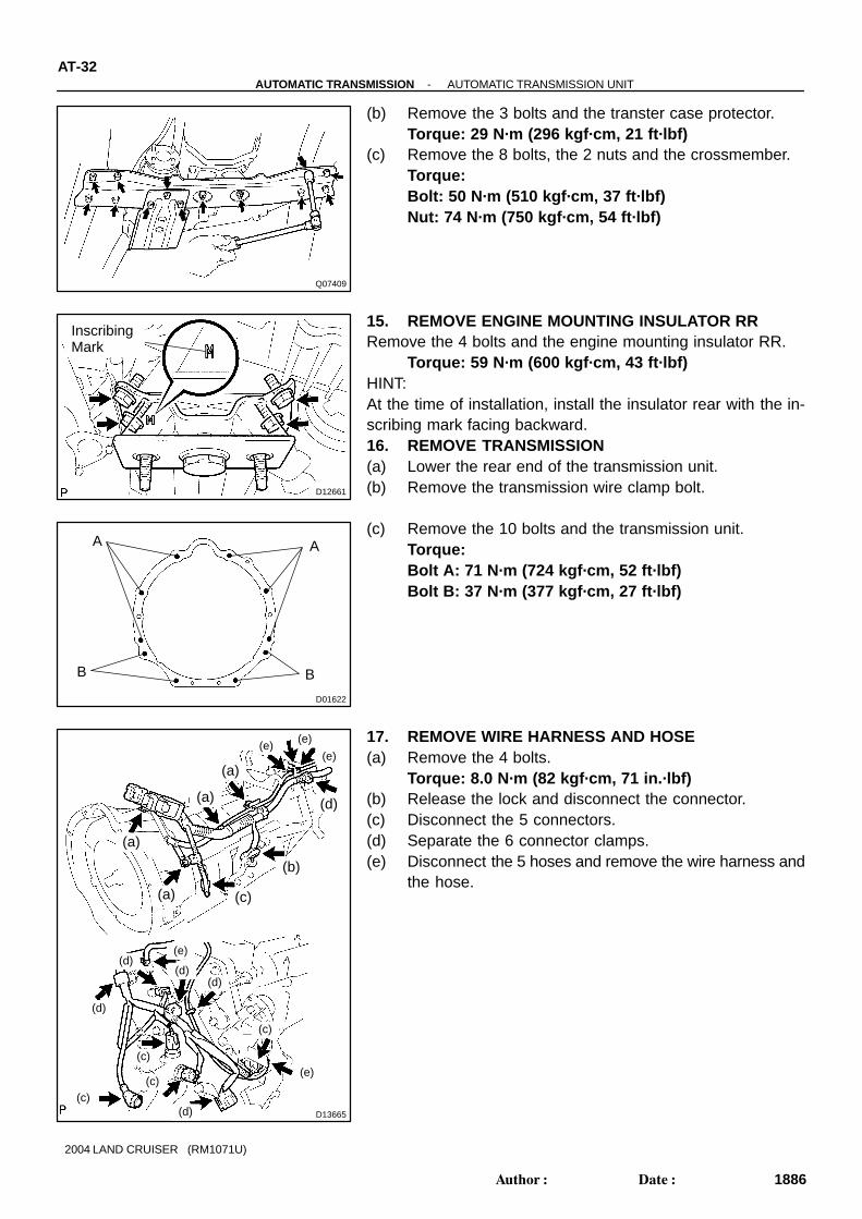
(b) Remove the 3 bolts and the transter case protector.Torque: 29 N·m (296 kgf·cm, 21 ft·lbf)
(c) Remove the 8 bolts, the 2 nuts and the crossmember.Torque:Bolt: 50 N·m (510 kgf·cm, 37 ft·lbf)Nut: 74 N·m (750 kgf·cm, 54 ft·lbf)
15. REMOVE ENGINE MOUNTING INSULATOR RRRemove the 4 bolts and the engine mounting insulator RR.
Torque: 59 N·m (600 kgf·cm, 43 ft·lbf)HINT:At the time of installation, install the insulator rear with the in-scribing mark facing backward.16. REMOVE TRANSMISSION(a) Lower the rear end of the transmission unit.(b) Remove the transmission wire clamp bolt.
(c) Remove the 10 bolts and the transmission unit.Torque:Bolt A: 71 N·m (724 kgf·cm, 52 ft·lbf)Bolt B: 37 N·m (377 kgf·cm, 27 ft·lbf)
17. REMOVE WIRE HARNESS AND HOSE(a) Remove the 4 bolts.
Torque: 8.0 N·m (82 kgf·cm, 71 in.·lbf)(b) Release the lock and disconnect the connector.(c) Disconnect the 5 connectors.(d) Separate the 6 connector clamps.(e) Disconnect the 5 hoses and remove the wire harness and
the hose.

AT07S-04
D12638N·m (kgf·cm, ft·lbf) : Specified torque
Transmission Control Rod
x6
Shift Lever Assembly
Transfer Shift Lever Knob
Upper Console Panel
8.3 (85, 73 in.·lbf)
13 (130, 9)
AT-20-AUTOMATIC TRANSMISSION FLOOR SHIFT ASSEMBLY
1874Author: Date:
2004 LAND CRUISER (RM1071U)
FLOOR SHIFT ASSEMBLYCOMPONENTS

D12639
Position Indicator Housing
Position Indicator Light Guide
Slide Cover
No. 2 Slide Cover
Shift Lever NutShift Lever Guide Cushion
Shift Lever Guide Housing
Bracket
Shift Lock Control ECU
Coller
13 (130, 9)
Plate Washer
Spacer O-RingShift Lever Seal
O-Ring Spacer
Swivel
Plate Washer
Spacer
Shaft LowerControl Bush
clip
Plate Washer
Control Lever
Pin
Shift Lever Ring
Spring
Detent Shift Lever Pin
Shift LeverSub-assembly
Shift Lock Solenoid
Shift LeverNut
Pin
Shift Lever Knob
Transmission Control Switch ( ↔ D Position)
Shift LockControl Switch
Cap
Bulb
Indicator Light Wire
Shift Lock Release Button
Spring
N·m (kgf·cm, ft·lbf) : Specified torque
MP grease
Non-reusable part
Shift LeverPlate
Transmission Control Switch(2 ↔ L Position)
Shift LockSolenoid Link
ShiftLeverLock Pin
4.9 (50, 43 in.·lbf)
Shift Lock Release Cover
Cushion
Shift LockPlateStopper
-AUTOMATIC TRANSMISSION FLOOR SHIFT ASSEMBLYAT-21
1875Author: Date:
2004 LAND CRUISER (RM1071U)

AT114-01
D12642
D12643
-AUTOMATIC TRANSMISSION FLOOR SHIFT ASSEMBLYAT-23
1877Author: Date:
2004 LAND CRUISER (RM1071U)
DISASSEMBLY1. REMOVE SHIFT LEVER KNOB2. REMOVE POSITION INDICATOR HOUSING(a) Using a small screwdriver, remove the shift lock release
cover from the position indicator housing.(b) Remove the position indicator housing assembly.3. REMOVE POSITION INDICATOR LIGHT GUIDE(a) Disconnect the indicator lamp wire from the position indi-
cator light guide.(b) Remove the position indicator light guide.4. REMOVE SLIDE COVER AND NO. 2 SLIDE COVER5. REMOVE SHIFT LEVER GUIDE HOUSING(a) Disconnect the shift lock control ECU connector from the
shift lever plate.(b) Disconnect the 2 transmission control switches and the
shift lock control switch from the shift lever guide housing.
(c) Remove the 4 bolts, nuts and the shift lever guide housingassembly.
6. DISASSEMBLE SHIFT LEVER GUIDE HOUSING(a) Using a screwdriver, pry up the 3 shift lever nuts.(b) Using nippers, cut the 3 shift lever nuts off then.HINT:Remove the shift lever lock pin of the shift lever nut in the sameway.(c) Remove the shift lever guide cushion.(d) Remove the 3 screws, the shift lock control ECU and the
shift lock solenoid.(e) Remove the shift lock control ECU bracket from the shift
lock control ECU.(f) Disconnect the transmission control switch connector
from the shift lever guide housing.(g) Remove the shift lock release button and the spring.

D12644
D04836
D04855
D12645
AT-24-AUTOMATIC TRANSMISSION FLOOR SHIFT ASSEMBLY
1878Author: Date:
2004 LAND CRUISER (RM1071U)
(h) Using a screwdriver, pry up the shift lever nut.(i) Using nipper, cut the shift lever nut off then.(j) Remove the shift lever lock pin, the shift lock plate stopper
and the cushion.
7. DISCONNECT SHIFT LOCK CONTROL ECU, SHIFTLOCK SOLENOID, SHIFT LOCK CONTROL SWITCHAND TRANSMISSION CONTROL SWITCH
(a) Disengage the secondary locking device of the shift locksolenoid.
(b) Release the locking lug of the terminal 4 and 5, and pullthe terminals out from the rear.
HINT:Remove the transmission control switch in the same way.(c) Remove the shift lock solenoid.(d) Using 2 mm dia. steel wire, remove the pin and the shift
lock solenoid link from the shift lock solenoid plunger.
(e) Disengage the secondary locking device of the shift lockcontrol ECU.
(f) Release the locking lag of the terminal 1, 2 and 8 pull theterminals out from the rear.
(g) Remove the transmission control switch. (D↔ 4)(h) Release the locking lag of the terminal 5, 6 and 12 and pull
the terminals out from the rear.(i) Remove the transmission control switch. (2↔L)(j) Release the locking lag of the terminal 7 and 14 and pull
the terminals out from the rear.

D12646
D12647
D12648
D12649
-AUTOMATIC TRANSMISSION FLOOR SHIFT ASSEMBLYAT-25
1879Author: Date:
2004 LAND CRUISER (RM1071U)
(k) Remove the indicator lamp wire.
8. REMOVE SHIFT LEVER SUB-ASSEMBLY(a) Using a magnetic finger, remove the detent shift lever pin
and the spring.
(b) Using 2 screwdrivers, remove the shift lever ring.(c) Remove the pin and shift lever sub-assembly.
9. DISASSEMBLE SHIFT LEVER PLATE(a) Remove the nut, the control lever, the plate washer, the
2 spacers and the 2 O-rings.
(b) Using pliers, remove the clip.(c) Remove the swivel, the 2 plate washers, the shaft lower
control bush and the spacer.(d) Remove the shift lever seal.(e) Remove the 4 collars.(f) Remove the 2 spring nuts.

D12641
AT116-01
D12640
AT-28-AUTOMATIC TRANSMISSION FLOOR SHIFT ASSEMBLY
1882Author: Date:
2004 LAND CRUISER (RM1071U)
INSTALLATION1. INSTALL FLOOR SHIFT LEVER ASSEMBLY(a) Install the floor shift lever assembly with the 6 bolts.
Torque: 8.3 N·m (85 kgf·cm, 73 in.·lbf)(b) Connect the connector to the floor shift lever assembly.
2. INSTALL No.1 FLOOR SHIFT GEAR SHIFTING ROD(a) Shift into the N position.(b) Connect the No.1 floor shift gear shifting rod and the con-
necting rod swivel with the nut.Torque: 13 N·m (130 kgf·cm, 9 ft.·lbf)
3. INSTALL UPPER CONSOL PANNEL(See Page BO-84 )
4. INSTALL TRANSFER SHIFT LEVER KNOB

AT115-01
D12649
D12648
D04855
AT-26-AUTOMATIC TRANSMISSION FLOOR SHIFT ASSEMBLY
1880Author: Date:
2004 LAND CRUISER (RM1071U)
REASSEMBLY1. REASSEMBLE SHIFT LEVER PLATE(a) Install the 2 spring nuts.(b) Install the 4 collars.(c) Install the shift lever seal.
(d) Install the shaft lower control bush, the spacer, the 2 platewashers and the swivel.
(e) Using pliers, install the clip.
(f) Apply MP grease to 2 new O-rings.(g) Install the 2 O-rings, 2 new spacers, the plate washer, the
control lever and the nut.Torque: 13 N·m (130 kgf·cm, 9 ft·lbf)
2. INSTALL SHIFT LEVER SUB-ASSEMBLY(a) Apply MP grease to the pin.(b) Install the shift lever sub-assembly and pin.(c) Install the shift lever ring.(d) Apply MP grease to the detent shift lever pin and the
spring.(e) Install the detent shift lever pin and spring.
3. REASSEMBLE SHIFT LOCK SOLENOID(a) Apply MP grease to the shift lock solenoid link.(b) Install the shift lock solenoid link and the pin to the shift
lock solenoid plunger.(c) Install the shift lock solenoid link with shift lock solenoid
plunger and the spring to the shift lock solenoid.
D12642
-AUTOMATIC TRANSMISSION FLOOR SHIFT ASSEMBLYAT-27
1881Author: Date:
2004 LAND CRUISER (RM1071U)
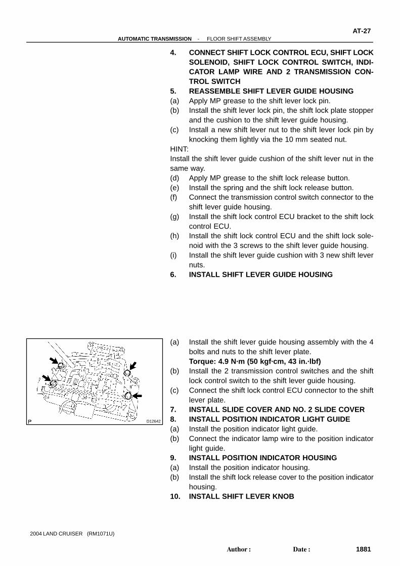
4. CONNECT SHIFT LOCK CONTROL ECU, SHIFT LOCKSOLENOID, SHIFT LOCK CONTROL SWITCH, INDI-CATOR LAMP WIRE AND 2 TRANSMISSION CON-TROL SWITCH
5. REASSEMBLE SHIFT LEVER GUIDE HOUSING(a) Apply MP grease to the shift lever lock pin.(b) Install the shift lever lock pin, the shift lock plate stopper
and the cushion to the shift lever guide housing.(c) Install a new shift lever nut to the shift lever lock pin by
knocking them lightly via the 10 mm seated nut.HINT:Install the shift lever guide cushion of the shift lever nut in thesame way.(d) Apply MP grease to the shift lock release button.(e) Install the spring and the shift lock release button.(f) Connect the transmission control switch connector to the
shift lever guide housing.(g) Install the shift lock control ECU bracket to the shift lock
control ECU.(h) Install the shift lock control ECU and the shift lock sole-
noid with the 3 screws to the shift lever guide housing.(i) Install the shift lever guide cushion with 3 new shift lever
nuts.6. INSTALL SHIFT LEVER GUIDE HOUSING
(a) Install the shift lever guide housing assembly with the 4bolts and nuts to the shift lever plate.Torque: 4.9 N·m (50 kgf·cm, 43 in.·lbf)
(b) Install the 2 transmission control switches and the shiftlock control switch to the shift lever guide housing.
(c) Connect the shift lock control ECU connector to the shiftlever plate.
7. INSTALL SLIDE COVER AND NO. 2 SLIDE COVER8. INSTALL POSITION INDICATOR LIGHT GUIDE(a) Install the position indicator light guide.(b) Connect the indicator lamp wire to the position indicator
light guide.9. INSTALL POSITION INDICATOR HOUSING(a) Install the position indicator housing.(b) Install the shift lock release cover to the position indicator
housing.10. INSTALL SHIFT LEVER KNOB
AT07T-04
D12640
D12641
AT-22-AUTOMATIC TRANSMISSION FLOOR SHIFT ASSEMBLY
1876Author: Date:
2004 LAND CRUISER (RM1071U)
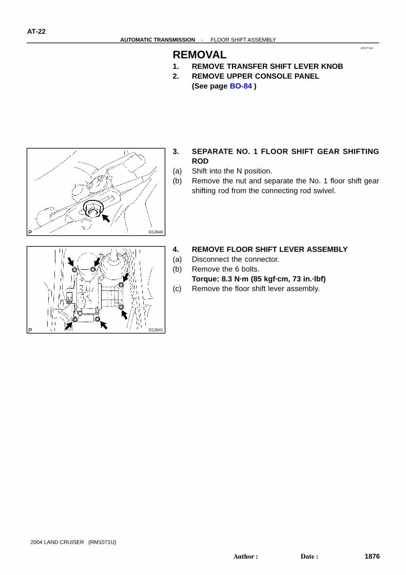
REMOVAL1. REMOVE TRANSFER SHIFT LEVER KNOB2. REMOVE UPPER CONSOLE PANEL
(See page BO-84 )
3. SEPARATE NO. 1 FLOOR SHIFT GEAR SHIFTINGROD
(a) Shift into the N position.(b) Remove the nut and separate the No. 1 floor shift gear
shifting rod from the connecting rod swivel.
4. REMOVE FLOOR SHIFT LEVER ASSEMBLY(a) Disconnect the connector.(b) Remove the 6 bolts.
Torque: 8.3 N·m (85 kgf·cm, 73 in.·lbf)(c) Remove the floor shift lever assembly.

AT112-01
D12708
D12709
D12710
D12708
AT-12-AUTOMATIC TRANSMISSION PARKING LOCK PAWL
1866Author: Date:
2004 LAND CRUISER (RM1071U)
PARKING LOCK PAWLON-VEHICLE REPAIR1. REMOVE VALVE BODY (See page AT-8 )
2. REMOVE PARKING LOCK PAWL BRACKET
3. REMOVE PARKING LOCK ROD
4. REMOVE SPRING FROM PARKING LOCK PAWLSHAFT
5. REMOVE PARKING LOCK PAWL AND SHAFT6. INSTALL PARKING LOCK PAWL AND SHAFT7. INSTALL SPRING TO PARKING LOCK PAWL SHAFT
8. INSTALL PARKING LOCK PAWL BRACKETHINT: Push the lock rod fully forward. Check that the parking lock pawl operates smoothly.
Torque: 7.4 N·m (75 kgf·cm, 65 in.·lbf)9. INSTALL VALVE BODY (See page AT-8 )

AT110-01
D12667
Lock Washer
-AUTOMATIC TRANSMISSION PARK/NEUTRAL POSITION (PNP) SWITCHAT-7
1861Author: Date:
2004 LAND CRUISER (RM1071U)
PARK/NEUTRAL POSITION (PNP)SWITCHON-VEHICLE REPAIR1. REMOVE ENGINE NO. 2 UNDER COVER2. DISCONNECT PARK/NEUTRAL POSITION SWITCH
CONNECTOR
3. REMOVE PARK/NEUTRAL POSITION SWITCH(a) Pry off the lock washer and remove the nut.(b) Remove the bolt and park/neutral position switch.4. INSTALL PARK/NEUTRAL POSITION SWITCH(a) Install the park/neutral position switch with the bolt.
Torque: 13 N·m (130 kgf·cm, 9 ft·lbf)(b) Install a new lock washer and the nut.
Torque: 6.9 N·m (70 kgf·cm, 62 in.·lbf)(c) Bent the claws on the lock washer to stake the nut.(d) Adjust the park/neutral position switch
(See page DI-361 ).5. CONNECT PARK/NEUTRAL POSITION SWITCH CON-
NECTOR6. INSTALL ENGINE NO. 2 UNDER COVER
AT07R-03
D12730
Connector A Connector BIG ACC
KLS+ESTP
PP2 SLS-
P1
SLS+
11
34
910
D12731
AT-14-AUTOMATIC TRANSMISSION SHIFT LOCK SYSTEM
1868Author: Date:
2004 LAND CRUISER (RM1071U)
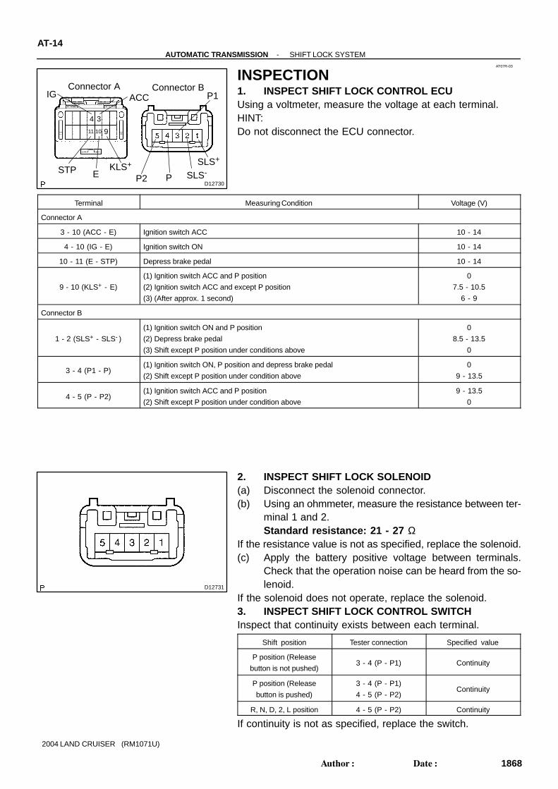
INSPECTION1. INSPECT SHIFT LOCK CONTROL ECUUsing a voltmeter, measure the voltage at each terminal.HINT:Do not disconnect the ECU connector.
Terminal Measuring Condition Voltage (V)
Connector A
3 - 10 (ACC - E) Ignition switch ACC 10 - 14
4 - 10 (IG - E) Ignition switch ON 10 - 14
10 - 11 (E - STP) Depress brake pedal 10 - 14
9 - 10 (KLS+ - E)
(1) Ignition switch ACC and P position
(2) Ignition switch ACC and except P position
(3) (After approx. 1 second)
0
7.5 - 10.5
6 - 9
Connector B
1 - 2 (SLS+ - SLS- )
(1) Ignition switch ON and P position
(2) Depress brake pedal
(3) Shift except P position under conditions above
0
8.5 - 13.5
0
3 - 4 (P1 - P)(1) Ignition switch ON, P position and depress brake pedal
(2) Shift except P position under condition above
0
9 - 13.5
4 - 5 (P - P2)(1) Ignition switch ACC and P position
(2) Shift except P position under condition above
9 - 13.5
0
2. INSPECT SHIFT LOCK SOLENOID(a) Disconnect the solenoid connector.(b) Using an ohmmeter, measure the resistance between ter-
minal 1 and 2.Standard resistance: 21 - 27 Ω
If the resistance value is not as specified, replace the solenoid.(c) Apply the battery positive voltage between terminals.
Check that the operation noise can be heard from the so-lenoid.
If the solenoid does not operate, replace the solenoid.3. INSPECT SHIFT LOCK CONTROL SWITCHInspect that continuity exists between each terminal.
Shift position Tester connection Specified value
P position (Release
button is not pushed)3 - 4 (P - P1) Continuity
P position (Release
button is pushed)
3 - 4 (P - P1)
4 - 5 (P - P2)Continuity
R, N, D, 2, L position 4 - 5 (P - P2) Continuity
If continuity is not as specified, replace the switch.

D03066
-AUTOMATIC TRANSMISSION SHIFT LOCK SYSTEMAT-15
1869Author: Date:
2004 LAND CRUISER (RM1071U)
4. INSPECT KEY INTERLOCK SOLENOID(a) Disconnect the solenoid connector.(b) Using an ohmmeter, measure the resistance between ter-
minal 1 and 2.Standard resistance: 12 - 17 Ω
If resistance value is not as specified, replace the solenoid.(c) Apply the battery positive voltage between terminals 1
and 2. Check that an operation noise can be heard fromthe solenoid.
If the solenoid does not operate, replace the solenoid.
AT07Q-03
D12729
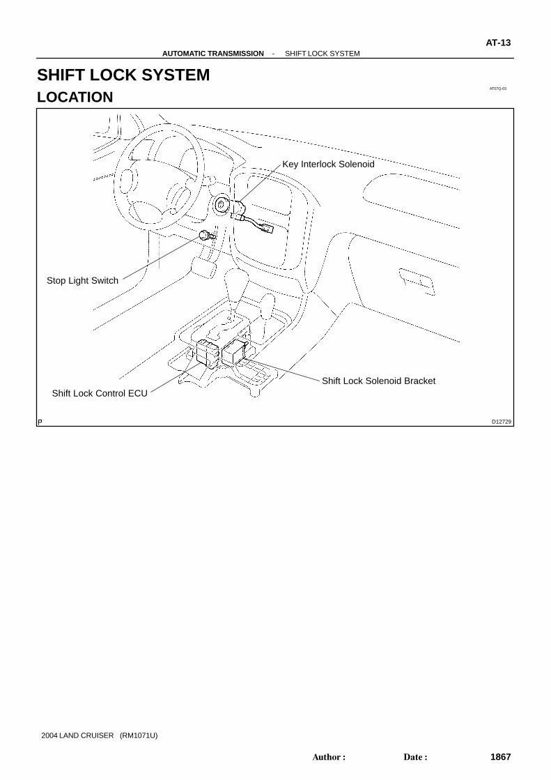
Key Interlock Solenoid
Stop Light Switch
Shift Lock Control ECUShift Lock Solenoid Bracket
-AUTOMATIC TRANSMISSION SHIFT LOCK SYSTEMAT-13
1867Author: Date:
2004 LAND CRUISER (RM1071U)
SHIFT LOCK SYSTEMLOCATION

AT5436
SST
AT07X-03
AT5437
Hold
TurnFree
Lock
Q04237
AT4184
AT-34-AUTOMATIC TRANSMISSION TORQUE CONVERTER CLUTCH AND DRIVE PLATE
1888Author: Date:
2004 LAND CRUISER (RM1071U)
TORQUE CONVERTER CLUTCHAND DRIVE PLATEINSPECTION1. INSPECT ONE-WAY CLUTCH(a) Install SST so that it fits in the notch of the converter hub
and outer race of the one-way clutch.SST 09350-30020 (09351-32020)
(b) Press on the serrations of stator with a finger and rotateit.
(c) Check if it rotates smoothly when turned clockwise andlocks up when turned counterclockwise.
If necessary, clean the converter clutch and retest the one-wayclutch.Replace the converter clutch if the clutch still fails in the test.
2. MEASURE DRIVE PLATE RUNOUT AND INSPECTRING GEAR
Set up a dial indicator and measure the drive plate runout.Maximum runout: 0.20 mm (0.0079 in.)
If runout is not within the specification or if the ring gear is dam-aged, replace the drive plate. If installing a new drive plate, notethe orientation of the spacers and tighten the bolts.
Torque:1st: 49 N·m (500 kgf·cm, 36 ft·lbf)2nd: Turn extra 90 °
3. MEASURE TORQUE CONVERTER CLUTCH SLEEVERUNOUT
(a) Temporarily mount the torque converter clutch to the driveplate. Set up a dial indicator and measure the torque converterclutch sleeve runout.Maximum runout: 0.30 mm (0.0118 in.)
If runout is not within the specification, correct it by reorientingthe installation of the torque converter clutch.If excessive runout cannot be corrected, replace the torqueconverter clutch.(b) Remove the torque converter clutch.
AT111-02
D13663
AT0103
D12703
D12704
Bolt
-AUTOMATIC TRANSMISSION VALVE BODY ASSEMBLY
AT-8
1862Author: Date:
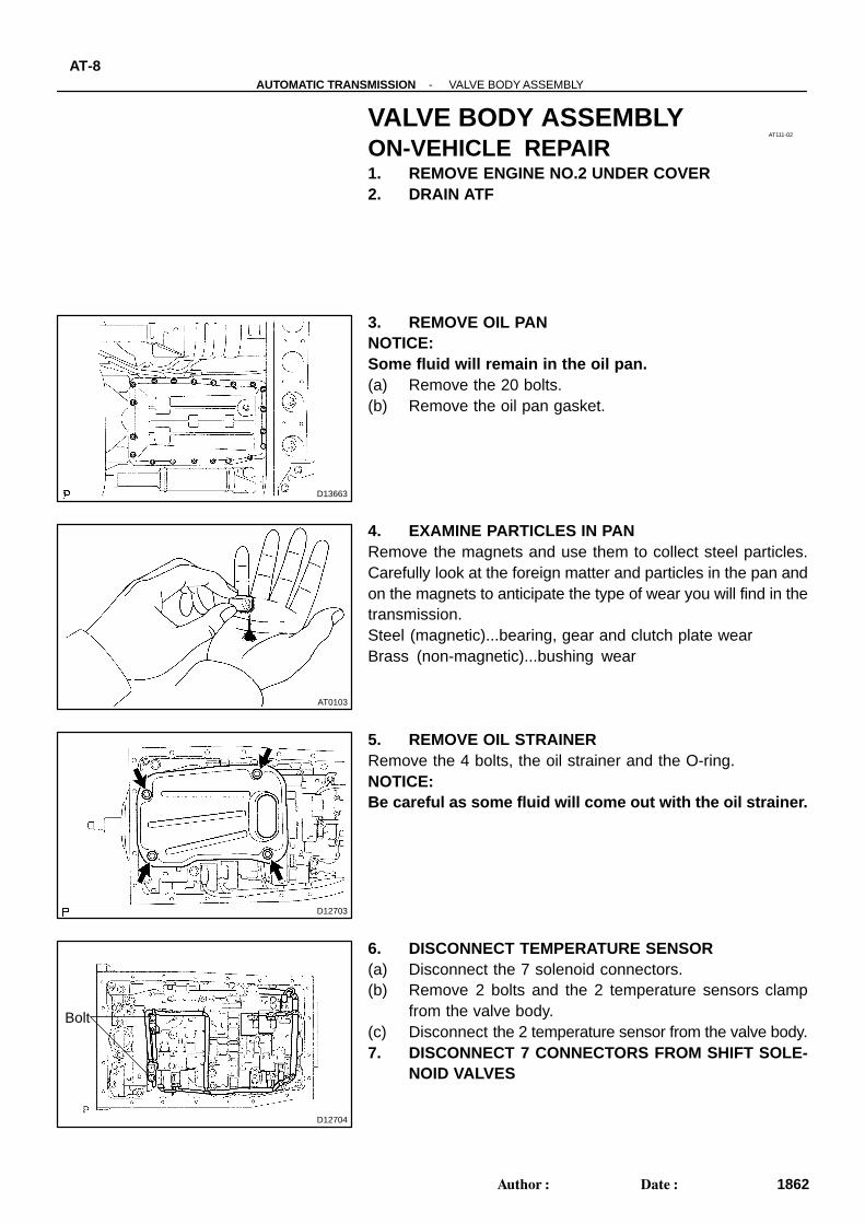
VALVE BODY ASSEMBLYON-VEHICLE REPAIR1. REMOVE ENGINE NO.2 UNDER COVER2. DRAIN ATF
3. REMOVE OIL PANNOTICE:Some fluid will remain in the oil pan.(a) Remove the 20 bolts.(b) Remove the oil pan gasket.
4. EXAMINE PARTICLES IN PANRemove the magnets and use them to collect steel particles.Carefully look at the foreign matter and particles in the pan andon the magnets to anticipate the type of wear you will find in thetransmission.Steel (magnetic)...bearing, gear and clutch plate wearBrass (non-magnetic)...bushing wear
5. REMOVE OIL STRAINERRemove the 4 bolts, the oil strainer and the O-ring.NOTICE:Be careful as some fluid will come out with the oil strainer.
6. DISCONNECT TEMPERATURE SENSOR(a) Disconnect the 7 solenoid connectors.(b) Remove 2 bolts and the 2 temperature sensors clamp
from the valve body.(c) Disconnect the 2 temperature sensor from the valve body.7. DISCONNECT 7 CONNECTORS FROM SHIFT SOLE-
NOID VALVES
D12705
D12706
ShiftSolenoidValve SL2
ShiftSolenoidValve SLU
ShiftSolenoidValve SR
ShiftSolenoidValve S2Shift
SolenoidValve S1
ShiftSolenoidValve SL1
ShiftSolenoidValve SLT
D12707
Pin
-AUTOMATIC TRANSMISSION VALVE BODY ASSEMBLYAT-9
1863Author: Date:
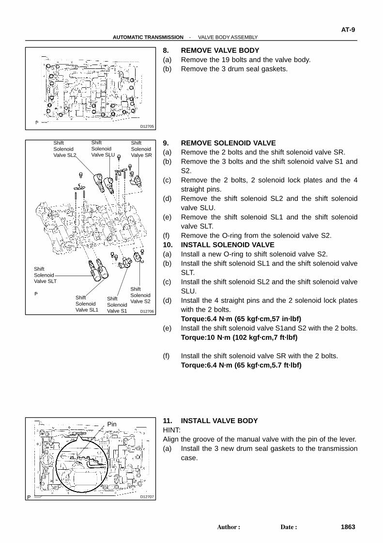
8. REMOVE VALVE BODY(a) Remove the 19 bolts and the valve body.(b) Remove the 3 drum seal gaskets.
9. REMOVE SOLENOID VALVE(a) Remove the 2 bolts and the shift solenoid valve SR.(b) Remove the 3 bolts and the shift solenoid valve S1 and
S2.(c) Remove the 2 bolts, 2 solenoid lock plates and the 4
straight pins.(d) Remove the shift solenoid SL2 and the shift solenoid
valve SLU.(e) Remove the shift solenoid SL1 and the shift solenoid
valve SLT.(f) Remove the O-ring from the solenoid valve S2.10. INSTALL SOLENOID VALVE(a) Install a new O-ring to shift solenoid valve S2.(b) Install the shift solenoid SL1 and the shift solenoid valve
SLT.(c) Install the shift solenoid SL2 and the shift solenoid valve
SLU.(d) Install the 4 straight pins and the 2 solenoid lock plates
with the 2 bolts.Torque:6.4 N·m (65 kgf·cm,57 in·lbf)
(e) Install the shift solenoid valve S1and S2 with the 2 bolts.Torque:10 N·m (102 kgf·cm,7 ft·lbf)
(f) Install the shift solenoid valve SR with the 2 bolts.Torque:6.4 N·m (65 kgf·cm,5.7 ft·lbf)
11. INSTALL VALVE BODYHINT:Align the groove of the manual valve with the pin of the lever.(a) Install the 3 new drum seal gaskets to the transmission
case.
D12705
A
A
A A A
A
AB
D12704
A
B
Orange
Blue
D12703
D13663
-AUTOMATIC TRANSMISSION VALVE BODY ASSEMBLY
AT-10
1864Author: Date:
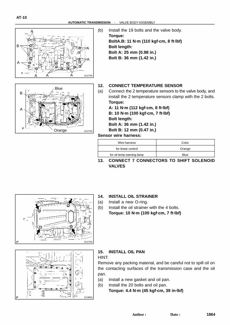
(b) Install the 19 bolts and the valve body.Torque: BoltA.B: 11 N·m (110 kgf·cm, 8 ft·lbf)Bolt length:Bolt A: 25 mm (0.98 in.)Bolt B: 36 mm (1.42 in.)
12. CONNECT TEMPERATURE SENSOR(a) Connect the 2 temperature sensors to the valve body, and
install the 2 temperature sensors clamp with the 2 bolts.Torque:A: 11 N·m (112 kgf·cm, 8 ft·lbf)B: 10 N·m (100 kgf·cm, 7 ft·lbf)Bolt length:Bolt A: 36 mm (1.42 in.)Bolt B: 12 mm (0.47 in.)
Sensor wire harness:
Wire harness Color
for linear control Orange
for oil temp warning lamp Blue
13. CONNECT 7 CONNECTORS TO SHIFT SOLENOIDVALVES
14. INSTALL OIL STRAINER(a) Install a new O-ring.(b) Install the oil strainer with the 4 bolts.
Torque: 10 N·m (100 kgf·cm, 7 ft·lbf)
15. INSTALL OIL PANHINT:Remove any packing material, and be careful not to spill oil onthe contacting surfaces of the transmission case and the oilpan.(a) Install a new gasket and oil pan.(b) Install the 20 bolts and oil pan.
Torque: 4.4 N·m (45 kgf·cm, 39 in·lbf)
-AUTOMATIC TRANSMISSION VALVE BODY ASSEMBLYAT-1 1
1865Author: Date:
16. FILL ATF AND CHECK ATF LEVEL(a) Install a new gasket and a drain plug.
Torque: 20 N·m (204 kgf·cm, 15 ft·lbf)(b) Remove the refill plug.(c) Fill new fluid through the refill hole (See page AT-3-1 ).17. INSTALL ENGINE NO.2 UNDER COVER

D12734
AT07Y-02
D12736
D12734
AT-4-AUTOMATIC TRANSMISSION VEHICLE SPEED SENSOR
1858Author: Date:
2004 LAND CRUISER (RM1071U)
VEHICLE SPEED SENSORON-VEHICLE REPAIR1. DISCONNECT NO. 1 VEHICLE SPEED SENSOR CON-
NECTOR
2. REMOVE NO. 1 VEHICLE SPEED SENSORRemove the bolt and the No. 1 vehicle speed sensor.3. DISASSEMBLE NO. 1 VEHICLE SPEED SENSOR(a) Remove the O-ring from the speedometer driven gear
assembly.(b) Remove the clip and the speedometer driven gear from
the speedometer driven gear sleeve.4. ASSEMBLE NO. 1 VEHICLE SPEED SENSOR(a) Install the speedometer driven gear and the clip to the
speedometer driven gear sleeve.(b) Coat a new O-ring with ATF.(c) Install the O-ring to the speedometer driven gear assem-
bly.5. INSTALL NO. 1 VEHICLE SPEED SENSORInstall the No. 1 vehicle speed sensor with the bolt.
Torque: 16 N·m (160 kgf·cm, 12 ft·lbf)
6. CONNECT NO. 1 VEHICLE SPEED SENSOR CON-NECTOR

D12737
Speed Sensor NT
Speed Sensor SP2
D02395
D12737
Speed Sensor NT
Speed Sensor SP2
-AUTOMATIC TRANSMISSION VEHICLE SPEED SENSORAT-5
1859Author: Date:
2004 LAND CRUISER (RM1071U)
7. DISCONNECT SPEED SENSOR NT AND SP2 CON-NECTORS
8. REMOVE SPEED SENSOR NT AND SP2(a) Remove the 2 bolts, speed sensor NT and SP2.
(b) Remove 2 O-rings from the speed sensor NT and SP2.9. INSTALL SPEED SENSOR NT AND SP2(a) Coat 2 new O-rings with ATF and install them to the
speed sensor NT and SP2.
(b) Install the speed sensor NT and SP2 with 2 bolts.Torque: 5.4 N·m (55 kgf·cm, 48 in.·lbf)
10. CONNECT SPEED SENSOR NT AND SP2 CONNEC-TORS