automatic transmission 37 automatic transmissionlinuzeus.net/arquivos/at.pdf · 37-4 automatic...
TRANSCRIPT

AUTOMATIC TRANSMISSION 37-1
37 Automatic Transmission
GENERAL 37-2
Transmission code location 37-2Automatic transmission fluid 37-3
AUTOMATIC TRANSMISSION ELECTRONICAND ELECTRICAL COMPONENTS ..... 37-11
Automatic transmission electronic andelectrical components (01M) 37-12
Automatic transmission electronic andelectrical components (09A) 37-15
Transmission Range (TR) switch,removing, installing, adjusting (01M) 37-17
Transmission Range (TR) switch,removing, installing, adjusting (09A) 37-17
BASIC SETTINGS 37-19
Basic settings, initiating 37-19Basic requirements 37-20
SHIFT MECHANISM 37-21
Shift mechanism, assembly (01M) 37-21Shift mechanism, assembly (09A) 37-24Selector lever cable, checkingand adjusting (01M) 37-27
Selector lever cable, checkingand adjusting (09A) 37-28
SHIFT LOCK 37-29
Shift lock cable,removing and installing (01M) 37-29
Shift lock cable, adjusting (01M) 37-31Shift lock cable,
removing and installing (09A) 37-33Shift lock cable, adjusting (09A) 37-35Shift lock operation, functional checking 37-36
TRANSMISSION, REMOVINGAND INSTALLING 37-37
Special tools, modifying (01M) 37-37Transmission, removing (01M) 37-37Transmission, transporting (01M) 37-45Transmission, installing (01M) 37-46Transmission, removing (09A) 37-48Transmission, transporting (09A) 37-55Transmission, installing (09A) 37-55
ATF COOLER 37-58
ATF cooler (01M) 37-59ATF cooler (09A) 37-60
TABLESa. 01M 4-speed automatic transmission
specifications 37-4b. 09A 5-speed automatic transmission
specifications 37-11
GENERAL
This section covers the 01M 4-speed, and the 09A 5-speedautomatic transmissions. Both automatic transmissions arecontrolled electro-hydraulically and feature adaptive programming and On-Board Diagnostic (OBO) capabilities.
Transmission Types
• 01M 4-speed automatic transmission
• 09A. . . . . . . . . . . . . 5-speed automatic transmission
NOTE-• For information on drive axles, including drive flange
oil seals, see 39 Differential and Final Drive.
• ATF draining and filling procedures, including ATF screen(filter) replacement, is covered in 0 Maintenance.
GENERAL
37-2
GENERAL
AUTOMATIC TRANSMISSION
I N37-0180 I
I N37-0655 I
WARNING-• Before working on the transmission or gear selector mechanism, disconnect the negative (-)battery cable.
• Disconnecting the negative (-) battery cable mayerase fault codes and basic settings in the enginemanagement and automatic transmission controlmodules. Some driveability problems may be noticed until the system re-adapts to operating conditions. OBD /I readiness codes, which may berequired for emissions testing, may also beerased. Convenience electronics (alarm system,interior light control, power locks, mirrors, andwindows) will need to be re-set using a VAG1551/1552, VAS 5051/5052 or equivalent scantool or scan tool computer program.
Transmission code location
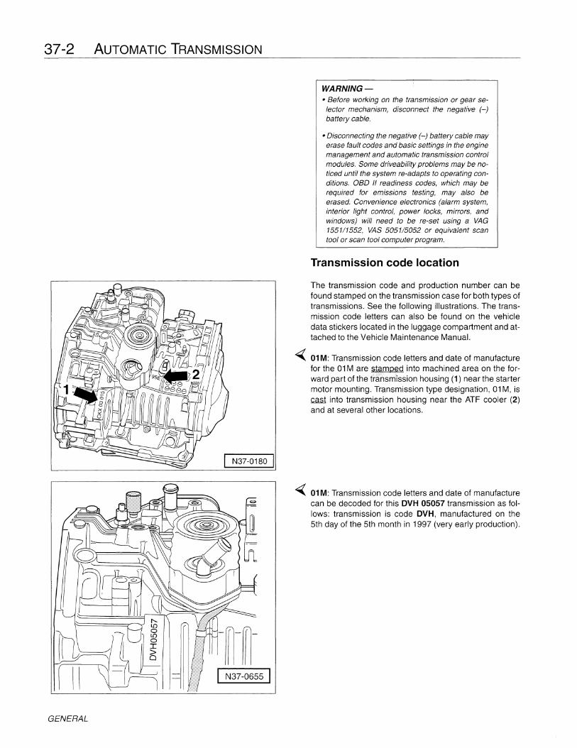
The transmission code and production number can befound stamped on the transmission case for both types oftransmissions. See the following illustrations. The transmission code letters can also be found on the vehicledata stickers located in the luggage compartment and attached to the Vehicle Maintenance Manual.
-( 01M: Transmission code letters and date of manufacturefor the 01Mare stamped into machined area on the forward part of the transmission housing (1) near the startermotor mounting. Transmission type designation, 01M, iscast into transmission housing near the ATF cooler (2)and at several other locations.
-( 01M: Transmission code letters and date of manufacturecan be decoded for this DVH 05057 transmission as follows: transmission is code DVH, manufactured on the5th day of the 5th month in 1997 (very early production).
AUTOMATIC TRANSMISSION 37-3
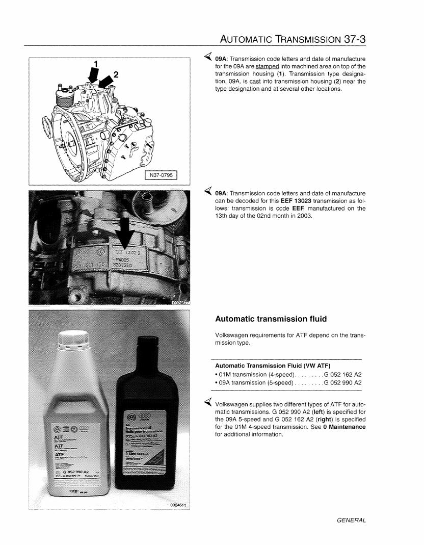
-( 09A: Transmission code letters and date of manufacturefor the 09A are §lamped into machined area on top of thetransmission housing (1). Transmission type designation, 09A, is cast into transmission housing (2) near thetype designation and at several other locations.
-( 09A: Transmission code letters and date of manufacturecan be decoded for this EEF 13023 transmission as follows: transmission is code EEF, manufactured on the13th day of the 02nd month in 2003.
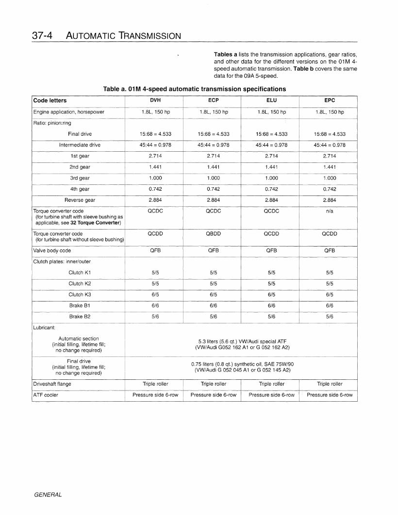
Automatic transmission fluid
Volkswagen requirements for ATF depend on the transmission type.
Automatic Transmission Fluid (VW ATF)
• 01M transmission (4-speed) G 052 162 A2• 09A transmission (5-speed) G 052 990 A2
-( Volkswagen supplies two different types of ATF for automatic transmissions. G 052 990 A2 (left) is specified forthe 09A 5-speed and G 052 162 A2 (right) is specifiedfor the 01M 4-speed transmission. See 0 Maintenancefor additional information.
GENERAL
37-4 AUTOMATIC TRANSMISSION
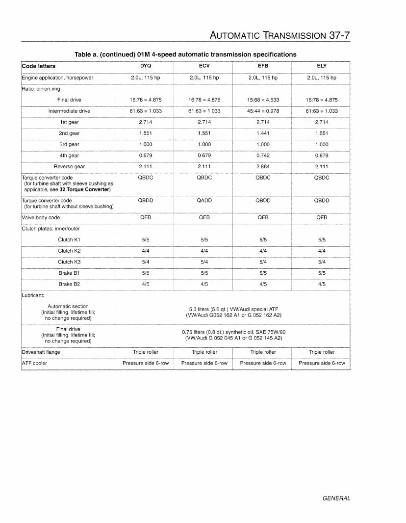
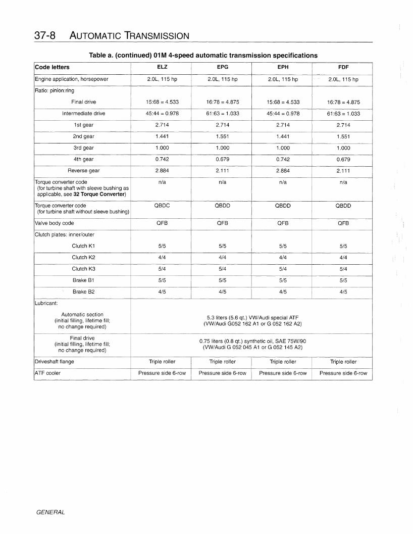
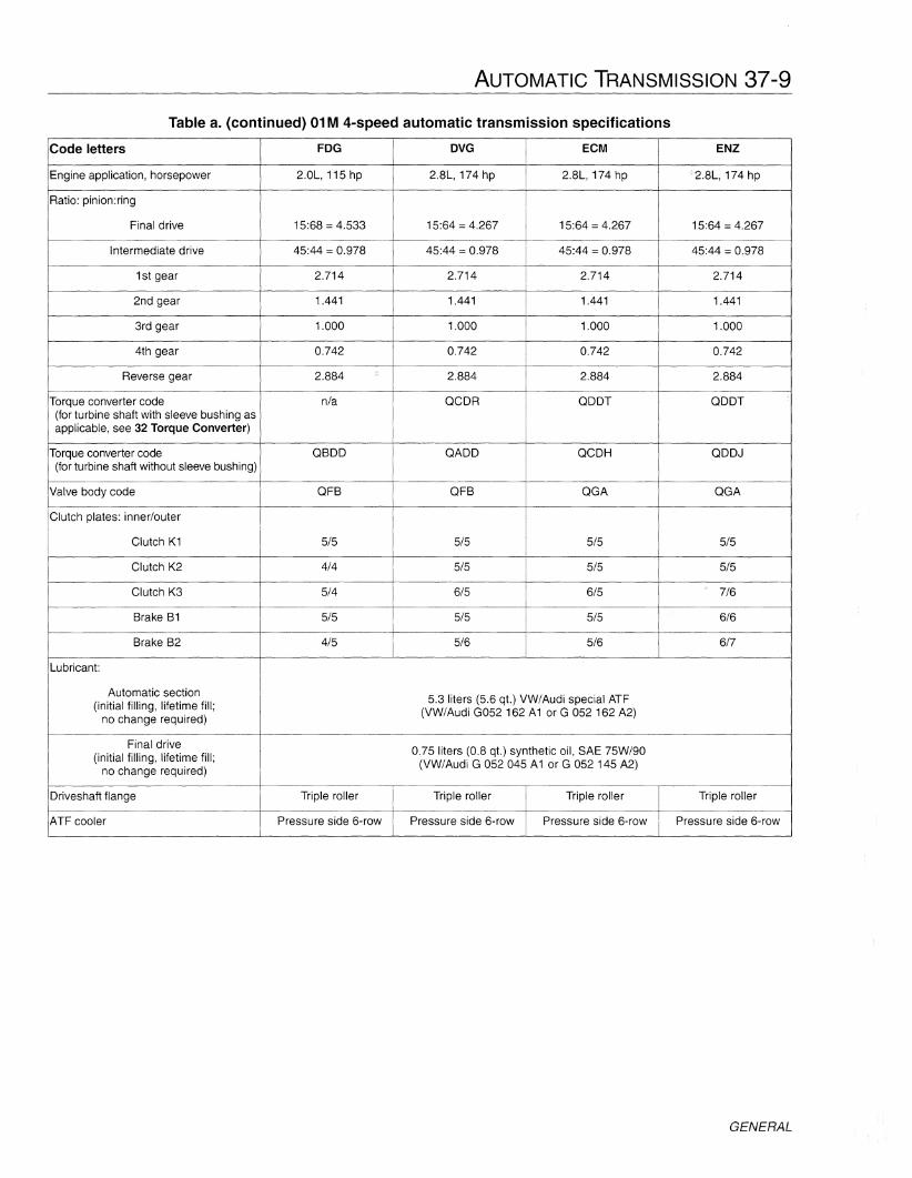
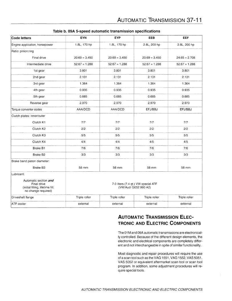
Tables a lists the transmission applications, gear ratios,and other data for the different versions on the 01M 4speed automatic transmission. Table b covers the samedata for the 09A 5-speed.
Table a. 01M 4-speed automatic transmission specifications
Code letters DVH ECP ELU EPC
Engine application, horsepower 1.8L, 150 hp 1.8L, 150 hp 1.8L, 150 hp 1.8L, 150 hp
Ratio: pinion:ring
Final drive 15:68 = 4.533 15:68 = 4.533 15:68 = 4.533 15:68 = 4.533
Intermediate drive 45:44 = 0.978 45:44 = 0.978 45:44 = 0.978 45:44 = 0.978
1st gear 2.714 2.714 2.714 2.714
2nd gear 1.441 1.441 1.441 1.441
3rd gear 1.000 1.000 1.000 1.000
4th gear 0.742 0.742 0.742 0.742
Reverse gear 2.884 2.884 2.884 2.884
Torque converter code QCOC QCOC QCOC n/a(for turbine shaft with sleeve bushing asapplicable, see 32 Torque Converter)
Torque converter code QCOO QBOO QCOO QCOO(for turbine shaft without sleeve bushing)
Valve body code QFB QFB QFB QFB
Clutch plates: inner/outer
Clutch K1 5/5 5/5 5/5 5/5
Clutch K2 5/5 5/5 5/5 5/5
Clutch K3 6/5 6/5 6/5 6/5
Brake B1 6/6 6/6 6/6 6/6
Brake B2 5/6 5/6 5/6 5/6
Lubricant:
Automatic section5.3 liters (5.6 qt.) VW/Audi special ATF
(initial filling, lifetime fill;no change required)
(VW/Audi G052 162 A1 or G 052 162 A2)
Final drive0.75 liters (0.8 qt.) synthetic oil, SAE 75W/90
(initial filling, lifetime fill;no change required)
(VW/Audi G 052045 A1 or G 052 145 A2)
Driveshaft flange Triple roller Triple roller Triple roller Triple roller
ATF cooler Pressure side 6-row Pressure side 6-row Pressure side 6-row Pressure side 6-row
GENERAL

AUTOMATIC TRANSMISSION 37-5
Table a. (continued) 01M 4-speed automatic transmission specifications
Code letters FOC OMP ECN ELT
Engine application, horsepower 1.8L, 150 hp 1.9L, 90 hp TOI 1.9L, 90 hp TOI 1.9L, 90 hp TOI
Ratio: pinion:ring
Final drive 15:68 =4.533 20:74 =3.700 20:74 =3.700 20:74 =3.700
Intermediate drive 45:44 =0.978 45:44 =0.978 45:44 =0.978 45:44 =0.978
1st gear 2.714 2.714 2.714 2.714
2nd gear 1.441 1.441 1.441 1.441
3rd gear 1.000 1.000 1.000 1.000
4th gear 0.742 0.742 0.742 0.742
Reverse gear 2.884 2.884 2.884 2.884
Torque converter code nla acoc acoc acoc(for turbine shaft with sleeve bushing asapplicable, see 32 Torque Converter)
Torque converter code acoo QCOO QCOO QCOD(for turbine shaft without sleeve bushing)
Valve body code QFB QFB QFB QFB
Clutch plates: innerlouter
Clutch K1 SiS SiS SiS SiS
Clutch K2 SiS SiS SiS SIS
Clutch K3 6/5 6/5 6/5 6/5
Brake B1 6/6 SiS SiS SiS
Brake B2 5/6 5/6 5/6 5/6
Lubricant:
Automatic section 5.3 liters (5.6 qt.) VW/Audi special ATF(initial filling, lifetime fill;
no change required)(VW/Audi G052 162 A1 or G 052 162 A2)
Final drive0.75 liters (0.8 qt.) synthetic oil, SAE 75W/90
(initial filling, lifetime fill;no change required)
(VW/Audi G 052 045 A1 or G 052 145 A2)
Oriveshaft flange Triple roller Triple roller Triple roller Triple roller
ATF cooler Pressure side 6-row Pressure side 6-row Pressure side 6-row Pressure side 6-row
GENERAL

37-6 AUTOMATIC TRANSMISSION
Table a. (continued) 01M 4-speed automatic transmission specifications
Code letters EPB EPP FOB OMN
Engine application, horsepower 1.9L, 90 hp TOI 1.9L, 90 hp TOI 1.9L, 90 hp TOI 2.0L, 115 hp
Ratio: pinion:ring
I
Final drive 20:74 =3.700 22:72 =3.273 20:74 =3.700 16:78 =4.875
Intermediate drive 45:44 =0.978 45:44 =0.978 45:44 =0.978 45:44 =0.978
1st gear 2.714 2.714 2.714 2.714
2nd gear 1.441 1.441 1.441 1.441
3rd gear 1.000 1.000 1.000 1.000
4th gear 0.742 0.742 0.742 0.742
Reverse gear 2.884 2.884 2.884 2.884
Torque converter code n/a nla nla QAOC(for turbine shaft with sleeve bushing asapplicable, see 32 Torque Converter)
Torque converter code QCOO QCOO QCOO QAOO(for turbine shaft without sleeve bushing)
Valve body code QFB QFA QFB QFBI
Clutch plates: innerlouter
Clutch K1 5/5 5/5 5/5 5/5
Clutch K2 5/5 5/5 5/5 4/4
Clutch K3 6/5 6/5 6/5 5/4
Brake B1 5/5 5/5 5/5 5/5
Brake B2 5/6 5/6 5/6 4/5
Lubricant:
Automatic section 5.3 liters (5.6 qt.) VW/Audi special ATF(initial filling, lifetime fill;
no change required)(VW/Audi G052 162 A1 or G 052 162 A2)
Final drive0.75 liters (0.8 qt.) synthetic oil, SAE 75W/90
(initial filling, lifetime fill;no change required)
(VW/Audi G 052 045 A1 or G 052 145 A2)
Oriveshaft flange Triple roller Triple roller Triple roller Triple roller
ATF cooler Pressure side 6-row Pressure side 6-row Pressure side 6-row Pressure side 6-row
GENERAL
AUTOMATIC TRANSMISSION 37-7
Table a. (continued) 01M 4-speed automatic transmission specifications
Code letters ovo ECV EFB ELY
Engine application, horsepower 2.0L, 115 hp 2.0L, 115 hp 2.0L, 115 hp 2.0L, 115 hpf----.
Ratio: pinion:ring
Final drive 16:78 = 4.875 16:78 = 4.875 15:68 = 4.533 16:78 = 4.875
Intermediate drive 61:63 = 1.033 61:63 = 1.033 45:44 = 0.978 61:63 = 1.033
1st gear 2.714 2.714 2.714 2.714
2nd gear 1.551 1.551 1.441 1.551
3rd gear 1.000 1.000 1.000 1.000
4th gear 0.679 0.679 0.742 0.679
Reverse gear 2.111 2.111 2.884 2.111
Torque converter code OBOC OBOC OBOC OBOC(for turbine shaft with sleeve bushing asapplicable, see 32 Torque Converter)
Torque converter code OBOO OAOO OBOO OBOO(for turbine shaft without sleeve bushing)
Valve body code OFB OFB OFB OFB
Clutch plates: inner/outer
Clutch K1 5/5 5/5 5/5 5/5
Clutch K2 4/4 4/4 4/4 4/4
Clutch K3 5/4 5/4 5/4 5/4
Brake B1 5/5 5/5 5/5 5/5
Brake 82 4/5 4/5 4/5I
4/5
Lubricant:
Automatic section5.3 liters (5.6 qt.) VW/Audi special ATF
(initial filling, lifetime fill;no change required)
(VW/Audi G052 162 A1 or G 052 162 A2)
Final drive0.75 liters (0.8 qt.) synthetic oil, SAE 75W/90
(initial filling, lifetime fill;no change required)
(VW/Audi G 052 045 A1 or G 052 145 A2)
Oriveshaft flange Triple roller Triple roller Triple roller Triple roller
ATF cooler Pressure side 6-row Pressure side 6-row Pressure side 6-row Pressure side 6-row
GENERAL
37-8 AUTOMATIC TRANSMISSION
Table a. (continued) 01M 4-speed automatic transmission specifications
Code letters ELZ EPG EPH FDF
Engine application, horsepower 2.0L, 115 hp 2.0L, 115 hp 2.0L, 115 hp 2.0L, 115 hp
Ratio: pinion:ring
Final drive 15:68 =4.533 16:78 =4.875 15:68 =4.533 16:78 =4.875
Intermediate drive 45:44 =0.978 61:63 =1.033 45:44 =0.978 61:63 =1.033
1st gear 2.714 2.714 2.714 2.714
2nd gear 1.441 1.551 1.441 1.551
3rd gear 1.000 1.000 1.000 1.000
4th gear 0.742 0.679 0.742 0.679
Reverse gear 2.884 2.111 2.884 2.111
Torque converter code nla nla nla nla(for turbine shaft with sleeve bushing asapplicable, see 32 Torque Converter)
Torque converter code OSOC OSOO OSDO OSOO(for turbine shaft without sleeve bushing)
Valve body code OFS QFS OFS OFS
Clutch plates: innerlouter
Clutch K1 5/5 5/5 5/5 5/5
Clutch K2 4/4 4/4 4/4 4/4
Clutch K3 5/4 5/4 5/4 5/4
Srake S1 5/5 5/5 5/5 5/5
Srake S2 4/5 4/5 4/5 4/5
Lubricant:
Automatic section5.3 liters (5.6 qt.) VW/Audi special ATF(initial filling, lifetime fill;
no change required)(VW/Audi G052 162 A1 or G 052 162 A2)
Final drive0.75 liters (0.8 qt.) synthetic oil, SAE 75W/90(initial filling, lifetime fill;
no change required)(VW/Audi G 052045 A1 or G 052 145 A2)
Oriveshaft flange Triple roller Triple roller Triple roller Triple roller
ATF cooler Pressure side 6-row Pressure side 6-row Pressure side 6-row Pressure side 6-row
GENERAL
AUTOMATIC TRANSMISSION 37-9
Table a. (continued) 01M 4-speed automatic transmission specifications
Code letters FOG OVG ECM ENZ
Engine application, horsepower 2.0L, 115 hp 2.8L, 174 hp 2.8L, 174 hp 2.8L, 174 hp
Ratio: pinion:ring
Final drive 15:68 =4.533 15:64 =4.267 15:64 =4.267 15:64 =4.267
Intermediate drive 45:44 =0.978 45:44 =0.978 45:44 =0.978 45:44 =0.978
1st gear 2.714 2.714 2.714 2.714
2nd gear 1.441 1.441 1.441 1.441
3rd gear 1.000 1.000 1.000 1.000
4th gear 0.742 0.742 0.742 0.742
Reverse gear 2.884 2.884 2.884 2.884
Torque converter code n/a QCDR QDDT QDDT(for turbine shaft with sleeve bushing asapplicable, see 32 Torque Converter)
Torque converter code QBDD QADD QCDH QDDJ(for turbine shaft without sleeve bushing)
Valve body code QFB QFB QGA QGA
Clutch plates: innerlouter
Clutch K1 5/5 5/5 5/5 5/5
Clutch K2 4/4 5/5 5/5 5/5
Clutch K3 5/4 6/5 6/5 7/6
Brake B1 5/5 5/5 5/5 6/6
Brake B2 4/5 5/6 5/6 6/7
Lubricant:
Automatic section5.3 liters (5.6 qt.) VW/Audi special ATF
(initial filling, lifetime fill;no change required)
(VW/Audi G052 162 A1 or G 052 162 A2)
Final drive0.75 liters (0.8 qt.) synthetic oil, SAE 75W/90
(initial filling, lifetime fill;no change required)
(VW/Audi G 052 045 A1 or G 052 145 A2)
Driveshaft flange Triple roller Triple roller Triple roller Triple roller
ATF cooler Pressure side 6-row Pressure side 6-row Pressure side 6-row Pressure side 6-row
GENERAL

37-10 AUTOMATIC TRANSMISSION
Table a. (continued) 01M 4-speed automatic transmission specifications
Code letters EPJ FCZ
Engine application, horsepower 2.8L, 174 hp 2.8L, 174 hp
Ratio: pinion:ring
Final drive 15:64 =4.267 15:64 =4.267
Intermediate drive 45:44 =0.978 45:44 =0.978
1st gear 2.714 2.714
2nd gear 1.441 1.441
3rd gear 1.000 1.000
4th gear 0.742 0.742
Reverse gear 2.884 2.884
Torque converter code n/a nla(for turbine shaft with sleeve bushing asapplicable, see 32 Torque Converter)
Torque converter code QDDJ QDDJ(for turbine shaft without sleeve bushing)
Valve body code QGA QGA
Clutch plates: innerlouter
Clutch K1 5/5 5/5
Clutch K2 5/5 5/5
Clutch K3 7/6 7/6
Brake B1 6/6 6/6
Brake B2 6/7 6/7
Lubricant:
Automatic section 5.3 liters (5.6 qt.) VW/Audi special ATF(initial filling, lifetime fill;
no change required)(VWIAudi G052 162 A1 or G 052 162 A2)
Final drive 0.75 liters (0.8 qt.) synthetic oil, SAE 75W/90(initial filling, lifetime fill;
no change required)(VW/Audi G 052 045 A1 or G 052 145 A2)
Driveshaft flange Triple roller Triple roller-- --
ATF cooler Pressure side 6-row Pressu re side 6-row
GENERAL
AUTOMATIC TRANSMISSION 37-11
Table b. 09A 5-speed automatic transmission specifications
Code letters EYN EYP EEB EEF
Engine application, horsepower 1.8L, 170 hp 1.8L, 170 hp 2.8L, 200 hp 2.8L, 200 hp
Ratio: pinion:ring
Final drive 20:69 =3.450 20:69 =3.450 20:69 =3.450 24:65 =2.708
Intermediate drive 52:67 =1.288 52:67 =1.288 52:67 =1.288 52:67 =1.288
1st gear 3.801 3.801 3.801 3.801
2nd gear 2.131 2.131 2.131 2.131
3rd gear 1.364 1.364 1.364 1.364
4th gear 0.935 0.935 0.935 0.935
5th gear 0.685 0.685 0.685 0.685
Reverse gear 2.970 2.970 2.970 2.970........•
Torque converter codes AAA/DCD AAA/DCD EFJ/BBJ EFJ/BBJ
Clutch plates: inner/outer
Clutch K1 7/7 7/7 7/7 7/7
Clutch K2 2/2 2/2 2/2 2/2
Clutch K3 5/5 5/5 5/5 5/5
Clutch K4 4/4 4/4 4/5 4/5
Brake B1 7/6 7/6 7/6 7/6f--- --
Brake B2 3/3 3/3 3/3 3/3
Brake band piston diameter:
Brake B3 58mm 58 mm 58mm 58mm
Lubricant:
Automatic section andFinal drive 7.0 liters (7.4 qt.) VW special ATF
(initial filling, lifetime fill; (VW/Audi G052 990 A2)no change required)
Driveshaft flange Triple roller Triple roller Triple roller Triple roller-1-----------
ATF cooler external external external external
AUTOMATIC TRANSMISSION ELECTRONIC AND ELECTRIC COMPONENTS
The 01M and 09A automatic transmissions are electronically controlled. Because of the different design elements, theelectronic and electrical components are completely different and not interchangeable in spite of similar functionality.
Most diagnostic and repair procedures will require the useof a scan tool such as the VAG 1551, VAG 1552, VAS 5051,VAS 5052 or equivalent aftermarket scan tool or scan toolprogram. In addition, some adjustment procedures will require special tools.
AUTOMATIC TRANSMISSION ELECTRONIC AND ELECTRIC COMPONENTS

37-12 AUTOMATIC TRANSMISSION
7
11
15 I0024486 I
6
16. Bolt• Tighten to 10 Nm (7 ft-Ib)
12. Cruise control switch (E45)
13. Kick down switch (F8)• Gasoline engines with cable op
erated throttle: integral with throttle cable and located onbulkhead in engine compartment
• Gasoline engines with Electronic Power Control, EPC: not aseparate component, functionis integral with Throttle PositionSensor, TPS
• Diesel engines: not a separatecomponent, function is integralwithThrottle PositionSensor,TPS
14. Brake light switch (F)• Located on brake pedal bracket
15. Park/Neutral Position, PNP relay (J226)• Located on additional relay panel
under instrument panel, left side• Marked with production number
"175"
10
11413
9
1 2
12
8
o
• Signal used by TCM only• Removing and installing,see VSS
(G68) removing and installing• Checked by OBO
9. Throttle position sensor (G69)• Gasoline engines with cable op
erated throttle: located on throttle valve housing, integral withthrottle valve control module
• Gasoline engines with ElectronicPower Control, EPC: located onaccelerator pedal, integral withThrottle Position Sensor, TPS
• Diesel engines: located on accelerator pedal, integral withThrottle Position Sensor, TPS
• Function, see TP sensor function
• Checked by OBO
10. Shift lock solenoid (N110)• Location, see Shift mecha
nism, assembly (01M).• Checked by OBO
11. Instrument cluster with OBDdata bus (J533)• With transmission selector lever
position display (Y5)
4. Valve body• Located above oil pan, bolted to
interior of transmission housing• Solenoid valves (N88, N89,
N90, N91, N92, N93, N94) areattached to the valve body
• Valves are checked by OnBoard Diagnostics (OBO)
5. Conductor strip (printed circuitfoil) with integrated AutomaticTransmission Fluid, (ATF) temperature sensor (G93)• Located in oil pan, attached to
valve body• Checked by OBO• Can be replaced without remov
ing valve body or transmission
6. Multi-function TransmissionRange, TR switch (F125)• Location, see Transmission
Range switch, location• Removing, installing, and adjust
ing, see Transmission Range(TR) switch, removing, installing, and adjusting (01M).
• Checked by OBO
7. Transmission vehicle speedsensor (G38)• Located on top of transmission
closer to engine• Signal used by TCM only• Removing and installing, see
Transmission VSS (G38) removing and installing
• Checked by OBO
8. Vehicle speed sensor (G68)• Located on top of transmission,
farther from engine
1. Transmission Control Module,TCM (J217)
• Located in air plenum, center/right• Factory coded, no user chang
es possible• Removing and installing, see
TCM removing and installing
2. Engine Control Module, ECM• Located in air plenum, center• Removing and installing, see 23
Fuel Injection-Diesel or 24Fuel Injection-Motronic (forappropriate engine code)
3. Data Link Connector (DLC)• Located under dashboard on
driver's side
Automatic transmissionelectronic and electricalcomponents (01M)
AUTOMATIC TRANSMISSION ELECTRONIC AND ELECTRIC COMPONENTS

AUTOMATIC TRANSMISSION 37-13
<liiI( TCM removing and installing
• Same position (arrow) and removal as for 09A TCM• Switch off ignition.• Remove wiper arms, rubber plenum seals, and inner
plenum cover.• Release multi-pin connector lock and slide connector
off toward center of vehicle.• Remove TCM mounting screws that are below connector.• Installation is the reverse.
NOTE-Use extra care when working around edges of windshield during plenum cover removal.
<liiI( TR switch, location
• On rear of transmission in cavity on transmission housing (2).
• Attached to extension wiring harness (1) running toconnector on upper transmission housing.
• TR switch can be disconnected at either point.
<liiI( Transmission VSS (G38) removing and installing
• Switch off ignition, remove harness connector and re-taining bolt. Pull straight out.
• When installing, replace seal.• Tighten retaining clamp bolt to 10 Nm (7 ft-Ib).• Signal used by transmission electronics only.
I N37-0181 I
AUTOMA TIC TRANSMISSION ELECTRONIC AND ELECTRIC COMPONENTS

37-14 AUTOMATIC TRANSMISSION
N01-0136 I
-( TP sensor function
• On vehicles with cable operated throttle, signal is sentto ECM which sends signal to the TCM via dedicatedwiring.
• On drive-by-wire vehicles with CAN-bus system, theTCM receives the TP sensor signal from the CAN-bus.
• The on-board diagnostics of the transmission onlychecks the signal, not the TP sensor. On vehicles without CAN-bus the wiring for the signal is also checked.
• Early version shown.
-( VSS, (G6a) removing and installing
• When transmission is installed the sensor is covered byleft transmission mount.
• Transmission must be unbolted from mounts and lowered approximately 2.5 in. to access sensor, seeTransmission, Removing and Installing.
• Switch off ignition, remove harness connector and re-taining bolt. Pull straight out.
• When installing, replace seal.• Tighten retaining clamp bolt to 10 Nm (7 ft-Ib).• Signal used by transmission electronics only.
AUTOMATIC TRANSMISSION ELECTRONIC AND ELECTRIC COMPONENTS
AUTOMATIC TRANSMISSION 37-15
87
14 I00244871
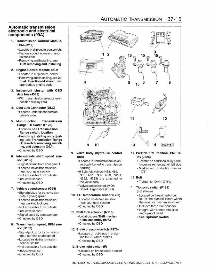
Tiptronic switch (F189)(not shown)• Located on the printed circuit
foil of the symbol insert withinthe selector mechanism cover
• Includes three Hall sensors• Integral with printed circuit foil
and symbol insert• See Tiptronic switch
*
15. Bolt• Tighten to 10 Nm (7 ft-Ib)
14. Park/Neutral Position, PNP relay (J226)• Located on additional relay panel
under instrument panel, left side• Marked with production number
"175"
11 12
5 15 6
9 10
9. Valve body (hydraullc controlunit)• Located in front of transmission,
vertically bolted to transmissionhousing
• 9 Solenoid valves (N88, N89,N90, N91, N92, N93, N281,N282, N283) are attached tothe valve body
• Valves are checked by anBoard Diagnostics (aBO)
10. ATF temperature sensor (G93)• Located inside transmission
near spur gear section• Checked by aBO
11. Shift lock solenoid (N110)• Location, see Shift mecha
nism, assembly (09A)• Checked by aBO
12. Brake pressure switch (F270)• Located on bulkhead in brake
line to R/F wheel brakes• Checked by aBO
13. Brake light switch (F)• Located on brake pedal bracket• Checked by aBO
8. Transmission speed, RPM sensor (G182)• Signal pickup for transmission
input (turbine shaft) speed• Located inside transmission
near clutch K2• Not accessible from outside• Inductive sensor• Checked by aBO
5. Multi-function TransmissionRange, TR switch (F125)• Location, see Transmission
Range switch, location• Removing, installing, and adjust
ing, see Transmission Range(TR) switch, removing, installing, and adjusting (09A).
• Checked by aBO
6. Intermediate shaft speed sensor (G265)• Signal pickup from spur gear A• Located inside transmission
near spur gear section• Not accessible from outside• Inductive sensor• Checked by aBO
7. Vehicle speed sensor (G68)• Signal pickup for transmission
output (road) speed• Located inside transmission
near parking lock gear• Not accessible from outside• Inductive sensor• Signal used by speedometer• Checked by aBO
1. Transmission Control Module,TCM (J217)
• Located inair plenum, center/right• Factory coded, no user chang
es possible• Removing and installing, see
TCM removing and installing
2. Engine Control Module, ECM• Located in air plenum, center• Removing and installing, see 24
Fuel Injection-Motronic (forappropriate engine code)
3. Instrument cluster with OBOdata bus (J533)• With transmission selector lever
position display (Y5)
4. Data Link Connector (OLC)• Located under dashboard on
driver's side
Automatic transmissionelectronic and electricalcomponents (09A)
AUTOMATIC TRANSMISSION ELECTRONIC AND ELECTRIC COMPONENTS
37-16 AUTOMATIC TRANSMISSION
N37-0805 I
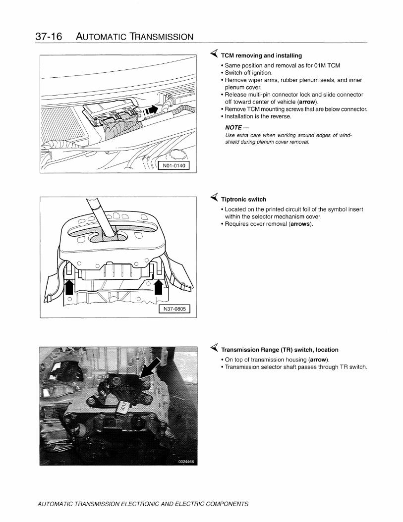
-( TCM removing and installing
• Same position and removal as for 01M TCM• Switch off ignition.• Remove wiper arms, rubber plenum seals, and inner
plenum cover.• Release multi-pin connector lock and slide connector
off toward center of vehicle (arrow).• Remove TCM mounting screws that are below connector.• Installation is the reverse.
NOTE-Use extra care when working around edges of windshield during plenum cover removal.
-( Tiptronic switch
• Located on the printed circuit foil of the symbol insertwithin the selector mechanism cover.
• Requires cover removal (arrows).
-( Transmission Range (TR) switch, location
• On top of transmission housing (arrow).• Transmission selector shaft passes through TR switch.
AUTOMA TIC TRANSMISSION ELECTRONIC AND ELECTRIC COMPONENTS

AUTOMATIC TRANSMISSION 37-17
Transmission range (TR) switch,removing, installing, adjusting (01M)
~ TR switch, removing and installing
• Switch off ignition, remove harness connector, bolt, andretaining bracket. Pull straight out.
• When installing, replace seal.• Tighten retaining clamp bolt to 10 Nm (7 ft-Ib).
- TR switch is adjusted correctly when properly installed.No separate adjust is possible.
N37-0620 I
Transmission range (TR) switch,removing, installing, adjusting (09A)
NOTE-Installation of TR switch requires special tool T10091for adjustment.
- Obtain anti-theft radio coding.
- Move selector lever into "P" position.
- Switch ignition off and disconnect battery ground strap.
Remove battery for access.
Remove battery carrier.
~ Remove nut (arrow) from selector shaft.
Pull lever (1) off selector shaft.
Pull off multi-function TR switch connector (2).
Remove three hex head securing bolts.
- Slide Multi-function TR switch F125 (3) up and off selector shaft.
AUTOMATIC TRANSMISSION ELECTRONIC AND ELECTRIC COMPONENTS

37-18 AUTOMATIC TRANSMISSION
~ To install, slide TR switch onto transmission selectorshaft and align groove (1) in selector shaft with indexmarkings (2) on TR switch.
~ Screw in three hex head securing bolts (arrows) fingertight only.
- Position adjusting device T10091 onto machined flats ofselector shaft and secure with attached set screw.
- Move selector shaft on transmission to neutral position.
- Turn TR switch until hole on switch housing (1) alignswith hole of adjusting tool.
Insert pin (2) from adjusting tool through hole in tool andinto hole in TR switch.
- Tighten 3 TR switch securing bolts.
Tightening torques
• TR switch securing bolts 6 Nm (53 in-Ib)
• Selector lever shaft nut 20 Nm (15 ft-Ib)
Install selector shaft lever and nut and tighten.
Remaining installation is the reverse of removal.
- Check selector cable adjustment,
AUTOMATIC TRANSMISSION ELECTRONIC AND ELECTRIC COMPONENTS
Rapid Data Transfer
Enter Address Word XX
Rapid Data Transfer
Select Function XX
Basic setting
Enter display group XXX
System in basic setting
HELP
0024490
HELP
0024491
HELP
0024492
--)
000
0024493
AUTOMATIC TRANSMISSION 37-19
BASIC SETTINGS
The Transmission Control Module (TCM) and the EngineControl Module (ECM) share data concerning engine andtransmission operation. Data that the TCM may not always precisely "know" is throttle range and full throttle position. The acquisition of this data is known as basicsetting. The basic setting influences automatic transmission shifting and is set at the time that the vehicle is new.
The basic setting will be lost and should be initiated aftercompletion of the following repairs:
• Engine removing and installing (replacement).• Transmission removing and installing.• Replacing or coding the Engine Control Module (ECM).• Replacing the Transmission Control Module (TCM).• Removing, installing, adjusting, and/or replacing elec
tronic throttle components at pedal or throttle housing.• If the battery is disconnected or runs down.• If the TCM is disconnected.
In these circumstances, the basic settings must be restored to insure proper automatic transmission operation.
Basic settings, initiating
Basic settings can be initiated or restored using a suitablescan tool. Follow the scan tool manufacturer's instructionsand/or use the procedure outlined below. In either case,the kickdown switch on the accelerator cable (where applicable) must function properly. Shown here is the displayfrom the VAG 1551. Others scan tool displays are similar.
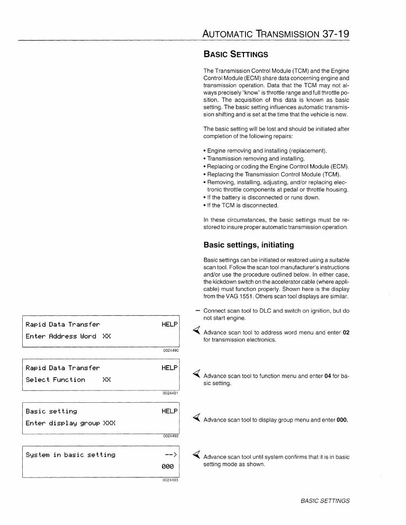
Connect scan tool to DLC and switch on ignition, but donot start engine.
Advance scan tool to address word menu and enter 02for transmission electronics.
~ Advance scan tool to function menu and enter 04 for basic setting.
~ Advance scan tool to display group menu and enter 000.
~ Advance scan tool until system confirms that it is in basicsetting mode as shown.
BASIC SETTINGS
37-20 AUTOMATIC TRANSMISSION
Push accelerator pedal all the way to the floor (past kickdown) and hold it there for a minimum of 3 seconds.
NOTE-Most scan tools and scan tool programs will not confirmcompletion of basic settings by anyon-screen display
Release accelerator pedal.
Exit program and disconnect scan tool.
Switch off the ignition.
Basic requirements
If transmission problems are experienced, the followingpoints should be considered before proceeding with indepth troubleshooting.
• Check ATF. Ensure that the level is correct and that thefluid is clean and of correct type, see 0 Maintenance.
• Make a visual inspection of the components shown forthe appropriate transmission system. Check the wiringand harness connectors for loose, damaged or corroded connections. Check that all related grounds are firmly connected and in good condition. Consult theappropriate wiring diagram, see 97 Wiring Diagrams,Fuses and Relays.
• Check the shift mechanism for proper function, seeShift Mechanism.
Review the conditions listed under Basic Settings. If anyof the conditions are met, the TCM must be reset to thebasic setting using an appropriate scan tool. If the TCMbasic settings are not re-established, driveability problems may be encountered. It may also be advantageousto reset the basic settings even if the listed repai rs havenot been done. This will assure that it is not a factor affecting driveability.
• If no faults are found up to this point, the next logicalstep is to check for faults using the a scan tool, or scantool computer program. If the transmission problem iselectrical/electronic in nature, specific DTCs will mostlikely be stored in memory.
BASIC SETTINGS
AUTOMATIC TRANSMISSION 37-21
SHIFT MECHANISM
The selector lever handle and shiftmechanism components for both the01M and 09A automatic transmissionsare different due, in part, to the additionof Tiptronic'" controls for the 09A.
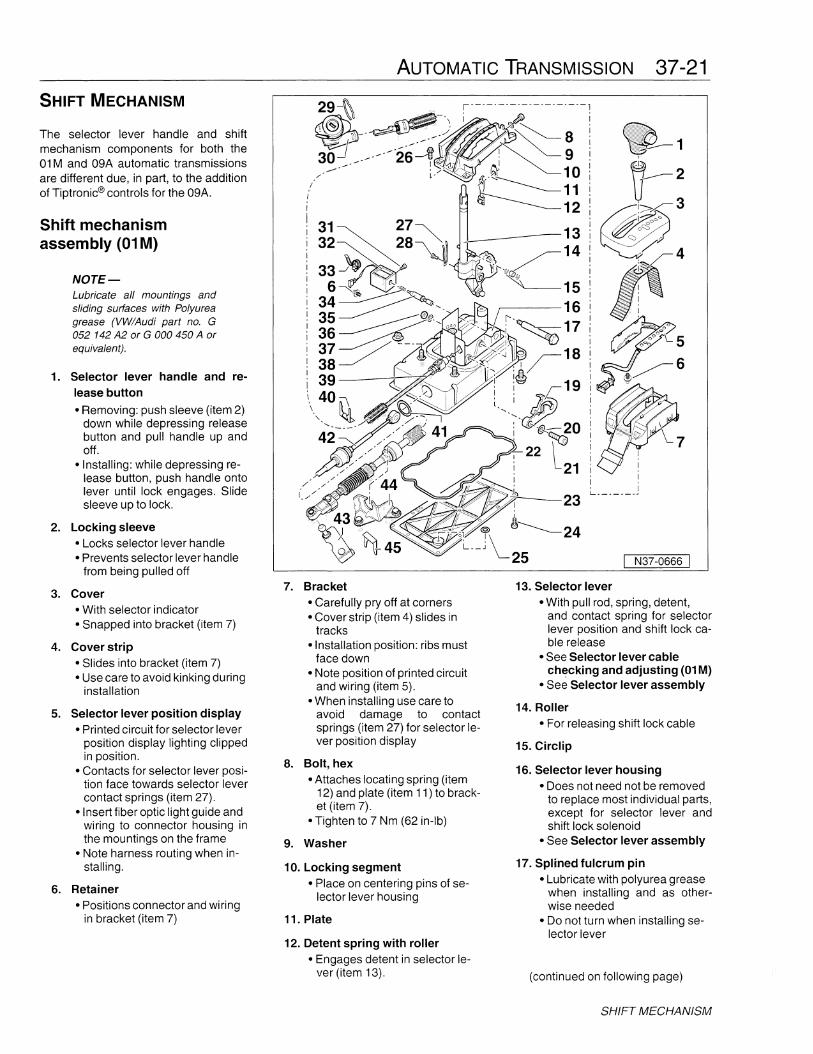
Shift mechanismassembly (01M)
NOTE-Lubricate all mountings andsliding surfaces with Polyureagrease (VW/Audi part no. G052 142 A2 or GOOD450 A orequivalent).
1. Selector lever handle and release button
• Removing: push sleeve (item 2)down while depressing releasebutton and pull handle up andoff.
• Installing: while depressing release button, push handle ontolever until lock engages. Slidesleeve up to lock.
2. Locking sleeve• Locks selector lever handle• Prevents selector lever handle
from being pulled off
3. Cover• With selector indicator• Snapped into bracket (item 7)
4. Cover strip• Slides into bracket (item 7)• Use care to avoid kinking during
installation
5. Selector lever position display• Printed circuit for selector lever
position display lighting clippedin position.
• Contacts for selector lever position face towards selector levercontact springs (item 27).
• Insert fiber optic light guide andwiring to connector housing inthe mountings on the frame
• Note harness routing when installing.
6. Retainer• Positions connector and wiring
in bracket (item 7)
i--~~) /Ai!P./~\fiI._30 _-------26~ ~I \
-- -' ! ,/,~,/ ~-
;'
I
7. Bracket• Carefully pry off at corners• Cover strip (item 4) slides in
tracks• Installation position: ribs must
face down• Note position of printed circuit
and wiring (item 5).• When installing use care to
avoid damage to contactsprings (item 27) for selector lever position display
8. Bolt, hex• Attaches locating spring (item
12) and plate (item 11) to bracket (item 7).
• Tighten to 7 Nm (62 in-Ib)
9. Washer
10. Locking segment• Place on centering pins of se
lector lever housing
11. Plate
12. Detent spring with roller• Engages detent in selector le
ver (item 13).
•.::.:..•..:::::.:...•...•...•....:...•....::.::.:::.·:::.:.:::.•:: :.:::......•.::.....•.
;zY111111111~~1
4
N37-0666 I
13. Selector lever• With pull rod, spring, detent,
and contact spring for selectorlever position and shift lock cable release
• See Selector lever cablecheckinq and adjusting (01M)
• See Selector lever assembly
14. Roller• For releasing shift lock cable
15. Circlip
16. Selector lever housing• Does not need not be removed
to replace most individual parts,except for selector lever andshift lock solenoid
• See Selector lever assembly
17. Splined fulcrum pin• Lubricate with polyurea grease
when installing and as otherwise needed
• Do not turn when installing selector lever
(continued on following page)
SHIFT MECHANISM
37-22 AUTOMATIC TRANSMISSION
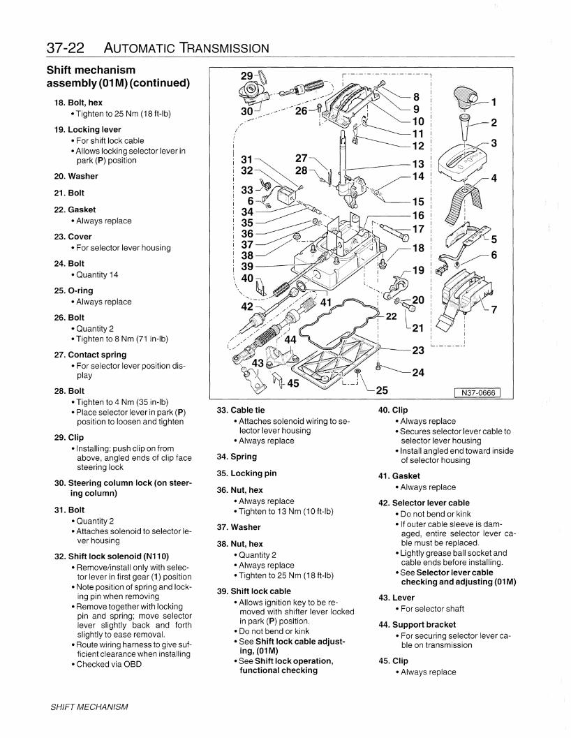
Shift mechanismassembly (01M) (continued)
18. Bolt, hex• Tighten to 25 Nm (18 ft-Ib)
19. Locking lever• For shift lock cable• Allows locking selector lever in
park (P) position
20. Washer
21. Bolt
22. Gasket• Always replace
23. Cover• For selector lever housing
24. Bolt
• Quantity 14
25. O-ring• Always replace
26. Bolt
• Quantity 2• Tighten to 8 Nm (71 in-Ib)
27. Contact spring• For selector lever position dis
play
28. Bolt• Tighten to 4 Nm (35 in-Ib)• Place selector lever in park (P)
position to loosen and tighten
29. Clip• Installing: push clip on from
above, angled ends of clip facesteering lock
30. Steering column lock (on steering column)
31. Bolt
• Quantity 2• Attaches solenoid to selector le
ver housing
32. Shift lock solenoid (N110)• Remove/install only with selec
tor lever in first gear (1) position• Note position of spring and lock
ing pin when removing• Remove together with locking
pin and spring; move selectorlever slightly back and forthslightly to ease removal.
• Route wiring harness to give sufficient clearance when installing
• Checked via aBO
SHIFT MECHANISM
33. Cable tie• Attaches solenoid wiring to se
lector lever housing• Always replace
34. Spring
35. Locking pin
36. Nut, hex
• Always replace• Tighten to 13 Nm (10 ft-Ib)
37. Washer
38. Nut, hex
• Quantity 2• Always replace• Tighten to 25 Nm (18 ft-Ib)
39. Shift lock cable• Allows ignition key to be re
moved with shifter lever lockedin park (P) position.
• Do not bend or kink• See Shift lock cable adjust
ing, (01M)• See Shift lock operation,
functional checking
4
N37-0666 I
40. Clip
• Always replace• Secures selector lever cable to
selector lever housing• Install angled end toward inside
of selector housing
41. Gasket
• Always replace
42. Selector lever cable
• Do not bend or kink• If outer cable sleeve is dam
aged, entire selector lever cable must be replaced.
• Lightly grease ball socket andcable ends before installing.
• See Selector lever cablechecking and adjusting (01M)
43. Lever• For selector shaft
44. Support bracket• For securing selector lever ca
ble on transmission
45. Clip• Always replace
AUTOMATIC TRANSMISSION 37-23
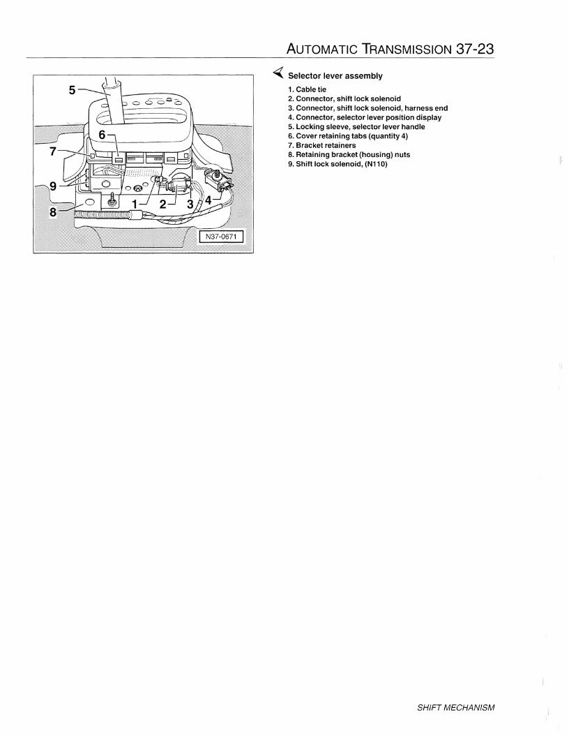
~ Selector lever assembly
1. Cable tie2. Connector, shift lock solenoid3. Connector, shift lock solenoid, harness end4. Connector, selector lever position display5. Locking sleeve, selector lever handle6. Cover retaining tabs (quantity 4)7. Bracket retainers8. Retaining bracket (housing) nuts9. Shift lock solenoid, (N110)
SHIFT MECHANISM

37-24 AUTOMATIC TRANSMISSION
Shift mechanismassembly (09A)
NOTE-Lubricate all mountings andsliding surfaces with Polyureagrease (VW/Audi part no. G052 142 A2 or GOOD 450 A orequivalent).
1. Selector lever handle and re-lease button
• Two different versions identifiedby colour. See Selector leverhandle identification.
• See, Selector lever handle re-moving and installing, early
• See, Selector lever handle re-moving and installing, late
2. Locking sleeve• Locks selector lever handle• Prevents selector lever handle
from being pulled off
3. Cover• With selector indicator• Snapped into bracket 5
4. Selector lever position display• Printed circuit for selector lever
position display lighting clippedin position.
• Note harness routing when in-stalling.
• Checked via aBO
5. Bracket• Cover strip slides in tracks
6. Cable clip
7. Bracket• For selector lever cable.• Attached to front tunnel heat
shield.
8. Locking plate• Secures selector lever cable to
mounting bracket• Always replace
9. Selector lever cable• Do not bend or kink• If outer cable sleeve is dam
aged, entire selector lever cable must be replaced.
• Do not grease cable eye andball socket.
• See Selector lever cablechecking and adjusting (09A)
SHIFT MECHANISM
_.---- .........
\
I
c;~
I7
10. Nut, self locking collared
• Quantity 4• Attaches to bolt 12• Always replace• Tighten to 10 Nm (7 ft-Ib)
11. Cover• For mounting bracket• With bonded seal
12. Bolt, hex• Quantity 4• Attaches to nut 10
13. Locking pawl• For shift lock• Locks into cable lever of mount
ing bracket.
14. Shift lock solenoid (N110)• Can be replaced with selector
mechanism installed.• Route wiring harness to give suf
ficient clearance when installing• Checked via aBO
15. Mounting bracket assembly• Mounting point for selector le
ver, detents and linkage.
·~--1
-:------2
-;-"'--- 3
6
~
N37-0772
16. Shift lock cable• Allows ignition key to be re
moved with shifter lever lockedin park (P) position.
• Do not bend or kink• See Shift lock cable adjust
ing, (09A)• See Shift lock operation,
functional checking
17. Steering column lock (on steering column)
18. Clip• Installing: push clip on from
above, angled ends of clip facesteering lock.
I N37-0981 I
I N37-0983 I
AUTOMATIC TRANSMISSION 37-25
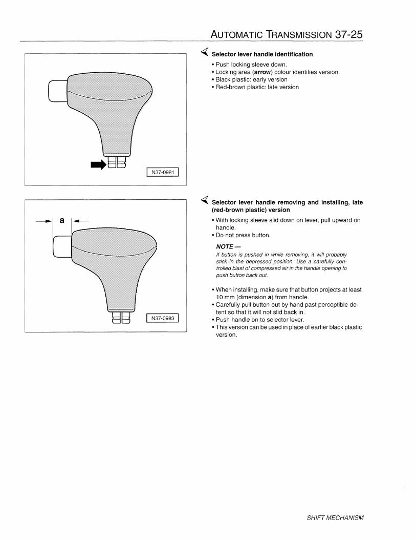
-( Selector lever handle identification
• Push locking sleeve down.• Locking area (arrow) colour identifies version.• Black plastic: early version• Red-brown plastic: late version
-( Selector lever handle removing and installing, late(red-brown plastic) version
• With locking sleeve slid down on lever, pull upward onhandle.
• Do not press button.
NOTE-If button is pushed in while removing, it will probablystick in the depressed position. Use a carefully controlled blast of compressed air in the handle opening topush button back out.
• When installing, make sure that button projects at least10 mm (dimension a) from handle.
• Carefully pull button out by hand past perceptible detent so that it will not slid back in.
• Push handle on to selector lever.• This version can be used in place of earlier black plastic
version.
SHIFT MECHANISM

37-26 AUTOMATIC TRANSMISSION
J N37-0767 I
~ Selector lever handle removing and installing, early(black plastic) version
• Move selector lever to position R.• Slide locking sleeve slid down on lever.• Pull button (2) out of handle (3) just enough so that pull
lever (arrow) hangs downward.• Pull handle off selector lever.• When installing, make sure selector lever is still in posi
tion R.• Pull button (2) out of handle (3) just enough so that pull
lever (arrow) hangs downward.• With button (2) towards driver, press handle down onto
stop.• Pull button (2) out further and guide pull lever (arrow)
into handle.• Press button (2) so that lever engages pull rod (4).• Button must now spring back to the stop.• Slide locking sleeve (1) upward in a twisting motion until
the two wide tabs of the sleeve fit into the slots of thehandle (3). The handle is locked when the sleeve canbe felt clipping into place.
• Move selector lever through all positions to check forproper operation and return to the park position.
• This version can be replaced by the red-brown plasticversion.
SHIFT MECHANISM

AUTOMATIC TRANSMISSION 37-27
Selector lever cable, checking andadjusting (01M)
Move selector lever into P position, switch ignition off andset parking brake.
Open hood and locate selector lever cable and selectorshaft lever on transmission.
~ Use a screwdriver to pry selector lever cable (1) off selector shaft lever (4) and move cable aside so that theend is free to move.
NOTE-Do not bend or kink selector lever cable.
Move selector lever from P to 1 to fully extend cable.
Check protective boot at front of selector cable for damage. If boot is damaged, replace selector cable
Move selector lever from 1 to P and check that shiftmechanism and selector lever cable move freely. If necessary replace selector lever cable or service shift mechanism as required.
Press selector cable (1) back onto selector shaft (4).
- To adjust cable, move selector lever into P position,switch ignition off and set parking brake.
Ensure that retaining clip (3) is properly seated and selector lever cable is secured on selector shaft lever.
Loosen adjustment bolt (2) at selector cable mount.
Ensure that selector shaft lever (4) is in position P ontransmission.
NOTE-With selector lever in P position, the transmission locking lever (pawl) must be engaged, locking both frontwheels.
With selector lever in P, tighten adjustment bolt (2). Ensure that circlip (3) is fully seated.
Shift through all gear positions and check for smooth operation.
Tightening torque
• Selector lever adjustment bolt 8 Nm (71 in-Ib)
SHIFT MECHANISM
37-28 AUTOMATIC TRANSMISSION
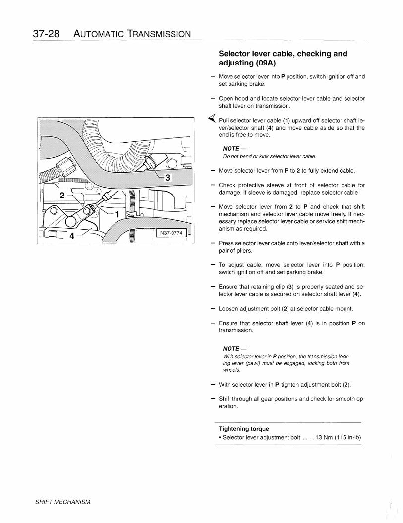
Selector lever cable, checking andadjusting (09A)
Move selector lever into P position, switch ignition off andset parking brake.
SHIFT MECHANISM
Open hood and locate selector lever cable and selectorshaft lever on transmission.
~ Pull selector lever cable (1) upward off selector shaft lever/selector shaft (4) and move cable aside so that theend is free to move.
NOTE-00 not bend or kink selector lever cable.
Move selector lever from P to 2 to fully extend cable.
Check protective sleeve at front of selector cable fordamage. If sleeve is damaged, replace selector cable
Move selector lever from 2 to P and check that shiftmechanism and selector lever cable move freely. If necessary replace selector lever cable or service shift mechanism as required.
Press selector lever cable onto lever/selector shaft with apair of pliers.
To adjust cable, move selector lever into P position,switch ignition off and set parking brake.
Ensure that retaining clip (3) is properly seated and selector lever cable is secured on selector shaft lever (4).
Loosen adjustment bolt (2) at selector cable mount.
Ensure that selector shaft lever (4) is in position P ontransmission.
NOTE-With selector lever in P position, the transmission locking lever (pawl) must be engaged, locking both frontwheels.
With selector lever in ~ tighten adjustment bolt (2).
Shift through all gear positions and check for smooth operation.
Tightening torque
• Selector lever adjustment bolt .... 13 Nm (115 in-Ib)

AUTOMATIC TRANSMISSION 37-29
SHIFT LOCK
Shift lock is used on all cars with automatic transmissionsOperation is essentially the same for both the 01M and09A transmissions. Shift lock is comprised of two mainsections, mechanical via a cable, and electro-mechanicalvia the shift lock solenoid.
The mechanical section of this feature is independent ofthe shift lock solenoid. Turning the ignition key on and offoperates a bowden cable to lock and unlock the selectorlever to enable the following:
Installation position of shift lock cable:
1. Footwell vents2. Instrument panel center support3. Heater box
The shift-lock cable is routed through the dashboard andunder the center console. Be sure to route the cable correctly when installing.
Shift lock cable,removing and installing (01M)
The electro-mechanical section of this feature is independent of the bowden cable. Turning the ignition key on operates a locking solenoid to lock and unlock the selectorlever to enable the following:
When the key is in the ON position, the cable pulls thestop lever away from the shift lever, allowing the shift lever to be moved out of park.
• Prevents movement of the shifter out of the Park, Reverse,or Neutral positions unless the brake pedal is depressed.
• Prevents removal of the ignition key from the ignitionlock unless the selector lever is in the Park (P) position.
• Prevents movement of the shifter unless the ignition keyis turned.
-( Operation of shift lock is similar for both the 01M and the09A transmissions. When the ignition key is turned to theoff position (shift lever in P), the cable pushes the stop lever into the shift lever. This locks the lever button and alsoallows the ignition key to be withdrawn from the lock cylinder. The key can only be removed from the ignition withthe lever in the P position. With the key out of the ignition,the selector lever cannot be shifted out of P position.
I N37-0665 I
Stop lever moves backto stop shift lever buttonfrom moving
Shift lever
SHIFT LOCK

37-30 AUTOMATIC TRANSMISSION
/
/
/
/
/I......
3
IJ---- 2
A37-0206 I
Disconnect battery ground (GND) strap from batterynegative (-) terminal. See the Cautions at the beginningof this repair group regarding battery disconnection.
NOTE-Be sure to have the anti-theft radio code on hand beforedisconnecting the battery.
Remove driver's side airbag and steering wheel. See 48Steering.
Remove trim under left side of instrument panel.
Remove handle for steering height and telescopic adjustment and covers for ignition/starter lock.
Turn ignition ON and move selector lever to P.
~ Remove shift lock cable clip (2) and pull cable (3) out ofignition/steering lock assembly (1).
Remove selector lever handle with release button.
SHIFT LOCK
Remove center console and extension, see 70 Trim-Interior.
~ Disconnect shift lock cable from locking lever at selectormechanism. Detach cable end from selector mechanismand press tabs (arrows) of shift lock cable retaining cliptogether while pulling locking cable out. Cable sleeve (1)and red clip (2) are utilized during adjustment procedure.
To install, guide cable between heater box and footwellvent behind instrument panel center support.
WARNING-• Be sure cable is routed correctly when installing.
• 00 not bend or kink cable.
• Be sure to adjust cable after installation.
Move selector lever to P.
Press shift lock cable into support bracket on selector lever housing until tabs (arrows) on retaining clip spreadapart.
Attach shift lock cable end in locking lever.
//
/
/
/
/<,
3
'''---2
A37-0206 I
AUTOMATIC TRANSMISSION 37-31
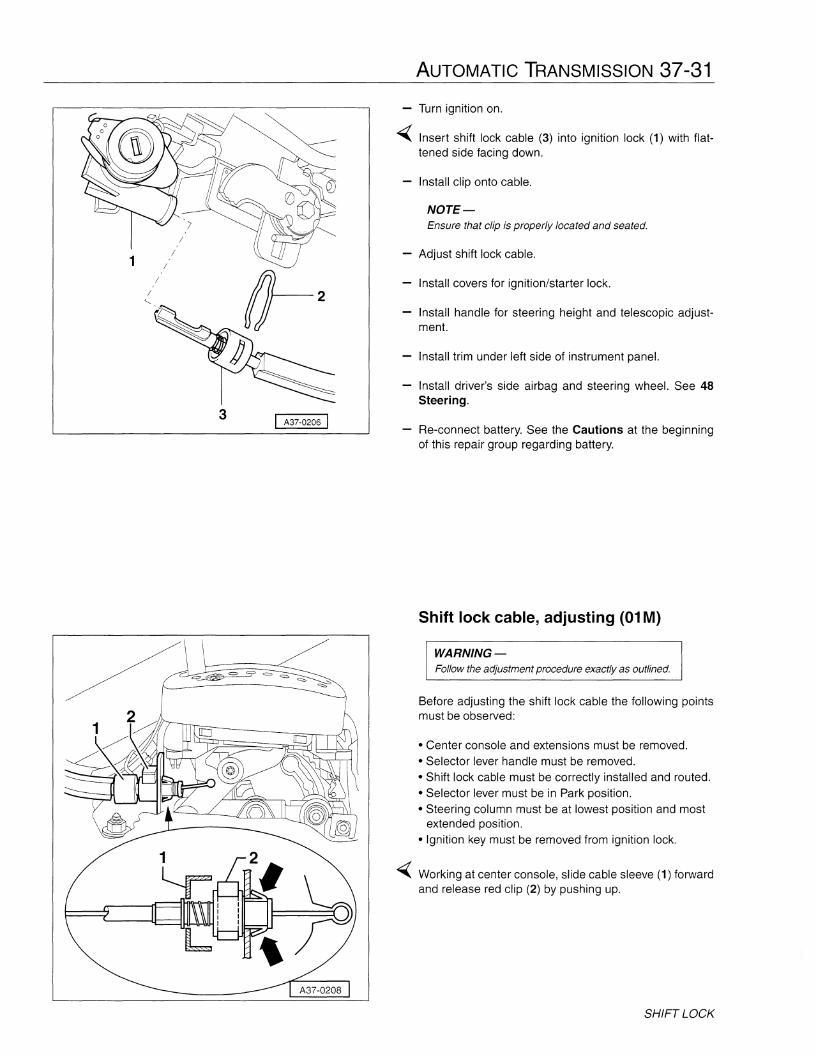
- Turn ignition on.
~ Insert shift lock cable (3) into ignition lock (1) with flattened side facing down.
Install clip onto cable.
NOTE-Ensure that clip is properly located and seated.
- Adjust shift lock cable.
Install covers for ignition/starter lock.
Install handle for steering height and telescopic adjustment.
Install trim under left side of instrument panel.
Install driver's side airbag and steering wheel. See 48Steering.
Re-connect battery. See the Cautions at the beginningof this repair group regarding battery.
Shift lock cable, adjusting (01M)
WARNING-Follow the adjustment procedure exactly as outlined.
Before adjusting the shift lock cable the following pointsmust be observed:
• Center console and extensions must be removed.• Selector lever handle must be removed.• Shift lock cable must be correctly installed and routed.• Selector lever must be in Park position.• Steering column must be at lowest position and most
extended position.• Ignition key must be removed from ignition lock.
~ Working at center console, slide cable sleeve (1) forwardand release red clip (2) by pushing up.
SHIFT LOCK
37-32 AUTOMATIC TRANSMISSION
SHIFT LOCK
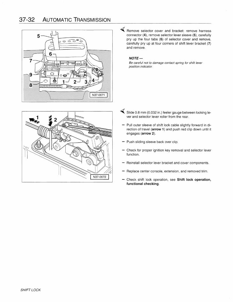
~ Remove selector cover and bracket: remove harnessconnector (4), remove selector lever sleeve (5), carefullypry up the four tabs (6) of selector cover and remove,carefully pry up at four corners of shift lever bracket (7)and remove.
NOTE-Be careful not to damage contact spring for shift leverposition indicator.
~ Slide 0.8 mm (0.032 in.) feeler gauge between locking lever and selector lever roller from the rear.
Pull outer sleeve of shift lock cable slightly forward in direction of travel (arrow 1) and push red clip down until itengages (arrow 2).
Push sliding sleeve back over clip.
Check for proper ignition key removal and selector leverfunction.
Reinstall selector lever bracket and cover components.
Replace center console, extension, and removed trim.
Check shift lock operation, see Shift lock operation,functional checking.
1
------
//
/
/
/
/<,
3
I N37-0665 I
1}-2
I N37-0773 I
AUTOMATIC TRANSMISSION 37-33
Shift lock cable,removing and installing (09A)
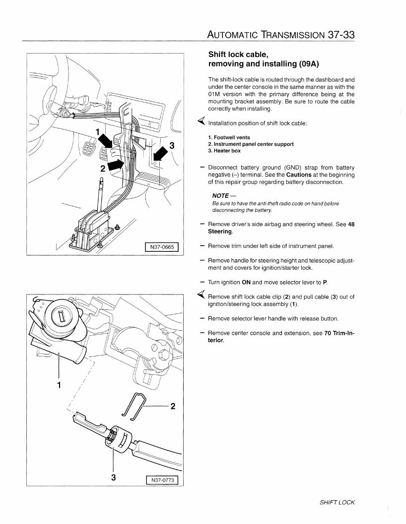
The shift-lock cable is routed through the dashboard andunder the center console in the same manner as with the01M version with the primary difference being at themounting bracket assembly. Be sure to route the cablecorrectly when installing.
Installation position of shift lock cable:
1. Footwell vents2. Instrument panel center support3. Heater box
Disconnect battery ground (GND) strap from batterynegative (-) terminal. See the Cautions at the beginningof this repair group regarding battery disconnection.
NOTE-Be sure to have the anti-theft radio code on hand beforedisconnecting the battery.
Remove driver's side airbag and steering wheel. See 48Steering.
Remove trim under left side of instrument panel.
Remove handle for steering height and telescopic adjustment and covers for ignition/starter lock.
- Turn ignition ON and move selector lever to P.
~ Remove shift lock cable clip (2) and pull cable (3) out ofignition/steering lock assembly (1).
Remove selector lever handle with release button.
Remove center console and extension, see 70 Trim-Interior.
SHIFT LOCK
37-34 AUTOMATIC TRANSMISSION
I N37-0813 I
N37-0807 I:"...
//
I N37-0813
SHIFT LOCK
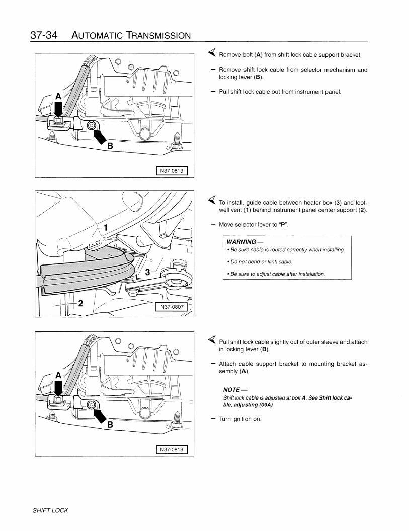
~ Remove bolt (A) from shift lock cable support bracket.
Remove shift lock cable from selector mechanism andlocking lever (B).
Pull shift lock cable out from instrument panel.
~ To install, guide cable between heater box (3) and footwell vent (1) behind instrument panel center support (2).
Move selector lever to "P".
WARNING-• Be sure cable is routed correctly when installing.
• Do not bend or kink cable.
• Be sure to adjust cable after installation.
~ Pull shift lock cable slightly out of outer sleeve and attachin locking lever (B).
- Attach cable support bracket to mounting bracket assembly (A).
NOTE-Shift lock cable is adjusted at bolt A. See Shift lock cable, adjusting (09A)
- Turn ignition on.

1
/
/
/
/
/<,
3352A
--2
I N37-0773 I
I N37-0775
AUTOMATIC TRANSMISSION 37-35
~ Insert shift lock cable (3) into ignition lock (1) with flattened side facing down.
Press clip (2) onto cable (3) from above. Ensure that angled ends of clip face ignition lock as illustrated.
NOTE-Ensure that clip is properly located and seated.
- Adjust shift lock cable.
Install covers for ignition/starter lock.
Install handle for steering height and telescopic adjustment.
Install trim under left side of instrument panel.
Install driver's airbag and steering wheel. See 48 Steering.
Re-connect battery. See the Cautions at the beginningof this repair group regarding battery.
Shift lock cable, adjusting (09A)
WARNING-Follow the adjustment procedure exactly as outlined.
Before adjusting the shift lock cable the following pointsmust be observed:
• Center console and extensions must be removed.• Shift lock cable must be correctly installed and routed.• Selector lever must be in Park position.• Steering column must be at lowest position and most
extended position.• Ignition key must be removed from ignition lock.
~ Working at center console, loosen bolt (at arrow) for shiftlock cable at support bracket.
Insert shift lock cable adjustment gauge 3352A betweenlocking lever (1) and locking cable eye (2).
- To adjust, take up free play by gently pulling shift lock cable forward (dashed arrow) and tighten bolt.
Adjustment gauge 3352A must be easy to remove andinsert when adjustment is correct. Readjust if required.
Tightening torque
• Support bracket adjustment bolt .... 10 Nm (7 ft-Ib)
Replace center console, extension, and removed trim.
Check shift lock operation, see Shift lock operation,functional checking
SHIFT LOCK

37-36 AUTOMATIC TRANSMISSION
Shift lock operation,functional checking
Start
~.
- Move seJectorlever to "P"
- Swilchlgoition off
- Withdrawrgnition key
Selector lever mechanism faulty or
steedng ~ock faufty
-Reptace faulty parts
No
Can selector lever be moved
out of"P" with button depressed?
No
Function OK
A
A
-Depress brake pedal
- lnsert ignition key
- Switch ignition on
Can selector lever be moved
out of "P'' with button depressed?
Yes
~ Yes ~ Adjustment of locking
cablemcorrect?
B
~ Yes -.
a
No
• Correct adjUstment
It must be possible to move selector 'lever into "R. N, D, 4, 3, or 2"
Can igntbonkey be withdrawn? Yes No
SHIFT LOCK
No- Depress brake peda~
- Move selector lever to "P"
Th€ ignitionkey canbe withdrawn
and the selector lever is bckedin "P"
Yes
Ignition key withdrawal lock OK.
VW 457/1
14,5
.. 125
I N34-0737 I
AUTOMATIC TRANSMISSION 37-37
TRANSMISSION, REMOVING ANDINSTALLING
This section describes the removal and installation procedure for both automatic transmission 01M and 09A.Several special tools are required along with special engine lifting and jacking equipment. These are needed tosupport and reposition the engine as the transmission isremoved from below.
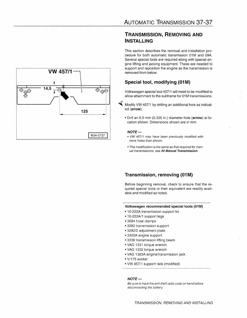
Special tool, modifying (01M)
Volkswagen special tool 457/1 will need to be modified toallow attachment to the subframe for 01M transmissions.
~ Modify VW 457/1 by drilling an additional hole as indicated (arrow).
• Drill an 8.5 mm (0.335 in.) diameter hole (arrow) at location shown. Dimensions shown are in mm.
NOTE-• VW 457/1 may have been previously modified with
more holes than shown.
• This modification is the same as that required for manual transmissions, see 34 Manual Transmission.
Transmission, removing (01M)
Before beginning removal, check to ensure that the required special tools or their equivalent are readily available and modified as noted.
Volkswagen recommended special tools (01M)
• 10-222A transmission support kit• 10-222A/1 support legs• 3094 hose clamps• 3282 transmission support• 3282/2 adjustment plate• 3300A engine support• 3336 transmission lifting beam• VAG 1331 torque wrench• VAG 1332 torque wrench• VAG 1383A engine/transmission jack• V/175 socket• VW 457/1 support rails (modified)
NOTE-Be sure to have the anti-theft radio code on hand beforedisconnecting the battery
TRANSMISSION, REMOVING AND INSTALLING

37-38 AUTOMATIC TRANSMISSION
TRANSMISSION, REMOVING AND INSTALLING
Remove engine cover.
Disconnect battery ground (GND) strap from batterynegative (-) terminal. See the Cautions at the beginningof this repair group regarding battery disconnection.
Disconnect battery positive (+) cable and remove batteryand battery tray. See 27 Engine Electrical.
~ Remove intake air hose (1), and harness connector (2),from Mass Air Flow (MAF) Sensor.
Remove vacuum hose (3) to air cleaner near MAF, whereequipped.
Remove complete air cleaner housing assembly by unscrewing bolts (4) and (5).
~ Disconnect harness connector for solenoid valves (1), vehicle speed sensor (2), Transmission Range (TR) switch(3), and transmission Vehicle Speed Sensor (VSS) (4).
NOTE-Disconnect TR switch and transmission VSS from extension harness connections on top of transmission ifequipped and move wiring to the side.
Remove bracket for power steering hose with retainer forwiring harness from transmission.
Move selector lever to park, P. Using a screwdriver, pryselector lever cable (1) off selector shaft lever (4). Adjustment bolt (2) should not be loosened.
Remove clip (3) at selector lever cable support bracketand remove selector lever cable.
NOTE-00 not bend or kink selector lever cable.

~~__1_0-_2j2 A)
AUTOMATIC TRANSMISSION 37-39
~ For all vehicles, disconnect ground cable (1) from upperengine/transmission bolt, electrical connections at starter motor (3, 4), and harness connector on top of startermotor (2).
Pull harness connector out of retainer on top of startermotor and remove retainer.
Remove upper starter mounting bolt.
~ Clamp-off ATF cooler hoses with special tool 3094clamps or equivalent and detach at ATF cooler. Seal ATFcooler with clean plugs.
Remove upper engine/transmission bolts.
~ On 4-cylinder engines, attach engine support tool 10222A with appropriate adapters and legs as shown. Adjust the support until the weight of the engine is fully supported.
WARNING-• Before installing the engine lifting hooks, disconnect all hoses and wiring in the vicinity of the engine lifting eyes, to prevent damage.
• Do not position engine sling legs on the fendermounting bolts.
TRANSMISSION, REMOVING AND INSTALLING
37-40 AUTOMATIC TRANSMISSION
TRANSMISSION, REMOVING AND INSTALLING
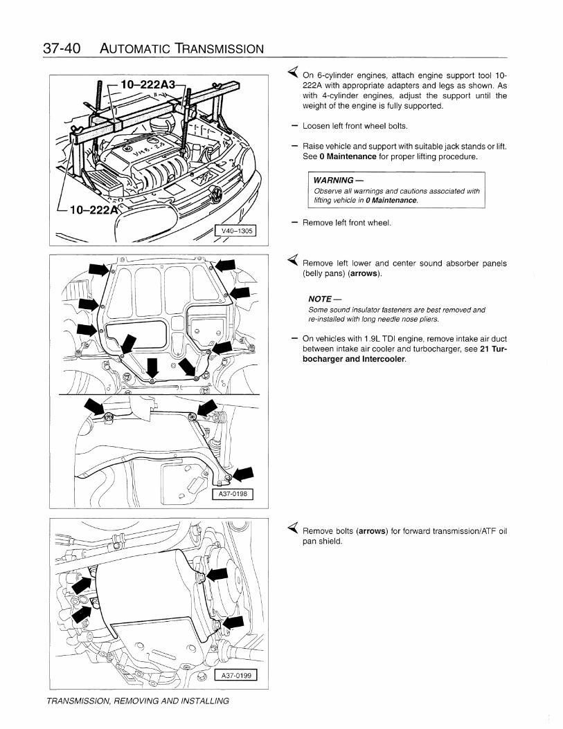
<Oiii( On 6-cylinder engines, attach engine support tool 10222A with appropriate adapters and legs as shown. Aswith 4-cylinder engines, adjust the support until theweight of the engine is fully supported.
Loosen left front wheel bolts.
Raise vehicle and support with suitable jack stands or lift.See 0 Maintenance for proper lifting procedure.
WARNING-Observe aI/ warnings and cautions associated withlifting vehicle in 0 Maintenance.
Remove left front wheel.
<Oiii( Remove left lower and center sound absorber panels(belly pans) (arrows).
NOTE-Some sound insulator fasteners are best removed andre-instal/ed with long needle nose pliers.
- On vehicles with 1.9L TOI engine, remove intake air ductbetween intake air cooler and turbocharger, see 21 Turbocharger and Intercooler.
<Oiii( Remove bolts (arrows) for forward transmission/ATF oilpan shield.

AUTOMATIC TRANSMISSION 37-41
~ Remove bracket (1) for power steering pressure line nearlower starter mounting bolt (arrow).
Remove lower starter mounting bolt and starter (2).
NOTE-Use care not to bend, kink, or damage the power steeringline.
~ Remove right inner drive axle boot shield (arrows) fromengine, if installed.
Unbolt both drive shafts at transmission drive flangesand secure (tie) up as high as possible.
NOTE-When tying up axle shafts use care not to damage thepaint on the body panels or the axles, or the axle boots.
~ Remove bolts for pendulum mount (arrows A and B).
TRANSMISSION, REMOVING AND INSTALLING
37-42 AUTOMATIC TRANSMISSION
\II II
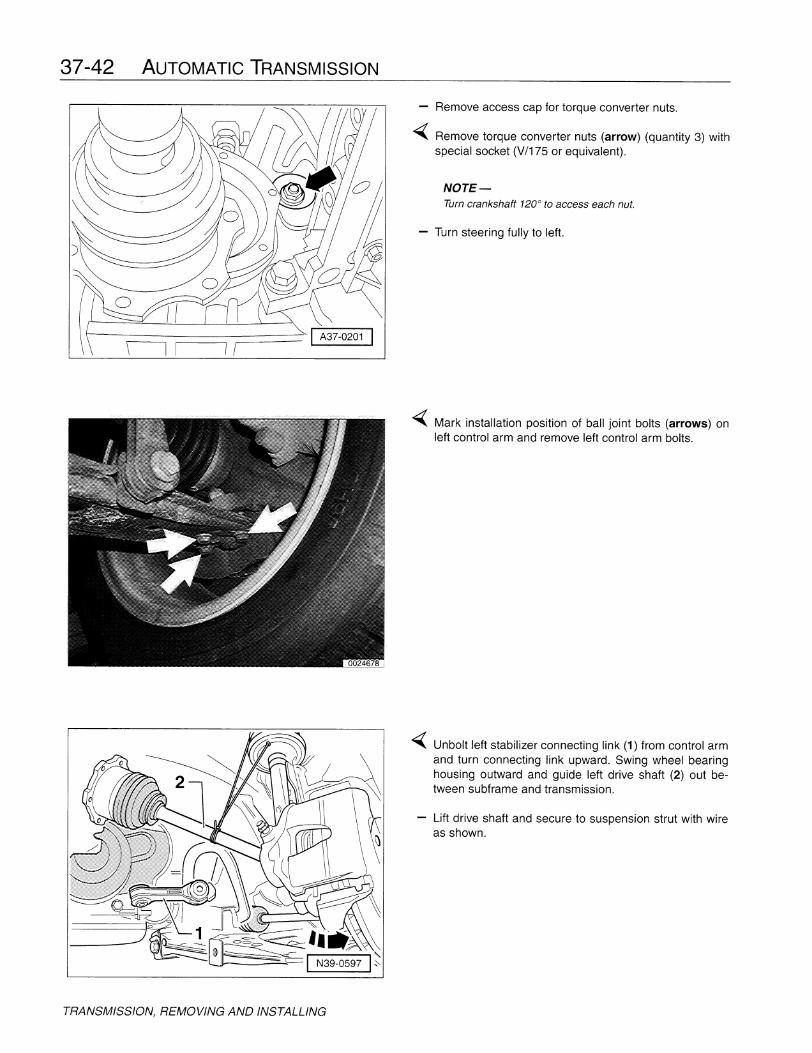
- Remove accesscap for torque converter nuts.
..;;;;;{ Remove torque converter nuts (arrow) (quantity 3) withspecial socket (V/175 or equivalent).
NOTE-Turn crankshaft 120 0 to access each nut.
- Turn steering fully to left.
TRANSMISSION, REMOVING AND INSTALLING
..;;;;;{ Mark installation position of ball joint bolts (arrows) onleftcontrol arm and remove leftcontrol arm bolts.
..;;;;;{ Unbolt left stabilizer connecting link (1) from control armand turn connecting link upward. Swing wheel bearinghousing outward and guide left drive shaft (2) out between subframe and transmission.
- Lift drive shaft and secure to suspension strut with wireas shown.
VW 457/1J N37-0660 I
AUTOMATIC TRANSMISSION 37-43
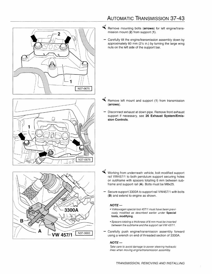
<Oiii{ Remove mounting bolts (arrows) for left engine/transmission mount (2) from support (1).
Carefully tilt the engine/transmission assembly down byapproximately 60 mm (2% in.) by turning the large wingnuts on the left side of the support bar.
<Oiii{ Remove left mount and support (1) from transmission(arrows).
Disconnect exhaust at down pipe. Remove front exhaustsupport if necessary, see 26 Exhaust System/Emission Controls.
<Oiii{ Working from underneath vehicle, bolt modified supportrail VW457/1 to both pendulum support securing holeson subframe with spacers totalling 6 mm between subframe and support rail (A). Bolts must be M8x25.
Secure support 3300A to support rail VW457/1 with bolts(B) and extend to engine as shown.
NOTE-• Volkswagen special tool 457/1 must have been previ
ously modified as described earlier under Specialtools, modifying.
• Spacers totaling a thickness of 6 mm must be insertedbetween the subframe and the support rail VW 457/1.
Carefully push engine/transmission assembly forwardusing a wrench on end of threaded section of 3300A.
NOTE-Take care to avoid damage to power steering hydrauliclines when moving engine/transmission assembly
TRANSMISSION, REMOVING AND INSTALLING

37-44 AUTOMATIC TRANSMISSION
IV37-1049 I
3282 IN37-0079 I
mli...y-~
\ I N37-0059 I
~ Assemble transmission jack with transmission supportfixture 3282, 3282/2 adjustment plate (marked096/01M), and support/clamping elements.
• Place adjustment plate 3282/2 on support fixture 3282noting that plate fits properly in one direction only andthat embossed arrow points to the front of the vehicle.
• Align arms of support fixture with holes in adjustmentplate and attach pins to arms as indicated on plate
NOTE-Arrow on adjustment plate 3282/2 must point towardfront of vehicle.
~ Place assembled transmission jack under transmission.
- Align adjustment plate to transmission and lock safetysupports on transmission jack.
~ Place safety support pin (arrow) on oil pan and secure itto transmission housing.
TRANSMISSION, REMOVING AND INSTALLING
AUTOMATIC TRANSMISSION 37-45
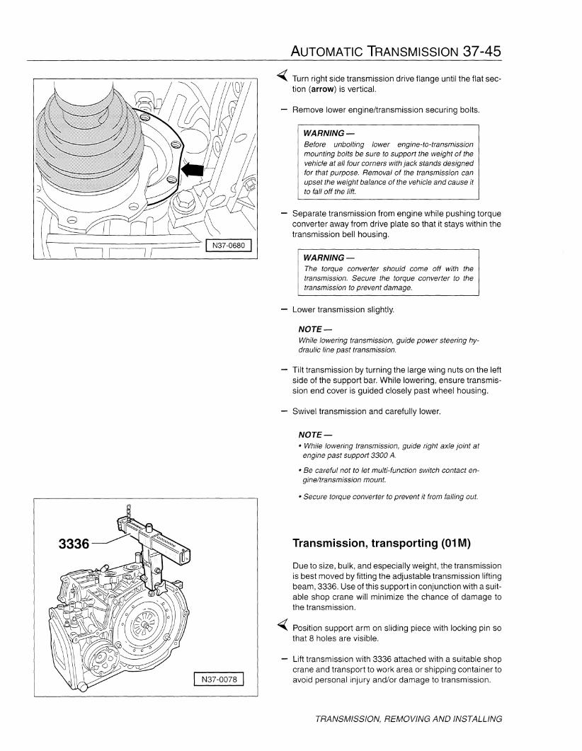
WARNING-The torque converter should come off with thetransmission. Secure the torque converter to thetransmission to prevent damage.
WARNING-Before unbolting lower engine-to-transmissionmounting bolts be sure to support the weight of thevehicle at all four corners with jack stands designedfor that purpose. Removal of the transmission canupset the weight balance of the vehicle and cause itto fall off the lift.
Remove lower engine/transmission securing bolts.
Separate transmission from engine while pushing torqueconverter away from drive plate so that it stays within thetransmission bell housing.
~ Turn right side transmission drive flange until the flat section (arrow) is vertical.
IIiiir--------------I N37-0680 I
Lower transmission slightly.
NOTE-While lowering transmission, quide power steering hydraulic line past transmission.
Tilt transmission by turning the large wing nuts on the leftside of the support bar. While lowering, ensure transmission end cover is guided closely past wheel housing.
Swivel transmission and carefully lower.
NOTE-• While lowering transmission, guide right axle joint at
engine past support 3300 A.
• Be careful not to let multi-function switch contact engine/transmission mount.
I N37-0078 I
• Secure torque converter to prevent it from falling out.
Transmission, transporting (01M)
Due to size, bulk, and especially weight, the transmissionis best moved by fitting the adjustable transmission liftingbeam, 3336. Use of this support in conjunction with a suitable shop crane will minimize the chance of damage tothe transmission.
Position support arm on sliding piece with locking pin sothat 8 holes are visible.
Lift transmission with 3336 attached with a suitable shopcrane and transport to work area or shipping container toavoid personal injury and/or damage to transmission.
TRANSMISSION, REMOVING AND INSTALLING
37-46 AUTOMATIC TRANSMISSION
VAS 5052
VAG 1552
VAG1551
I 0024463 I
Transmission, installing (01M)
NOTE-If torque converter has been removed, the torque converter seal will need to be replaced. See 32 TorqueConverter.
The transmission is installed in the reverse order of removal, noting the following:
When installing torque converter, be sure that both drivepins engage in the ATF pump inner wheel recesses.
Before installing transmission, be sure that the dowelsleeves are correctly located.
- When installing transmission, check that torque converter contact is properly positioned on drive plate.
Replace selector cable locking circlip.
Adjust selector lever cable, see Selector lever cable,checking and adjusting (01M).
Check and top up ATF level.
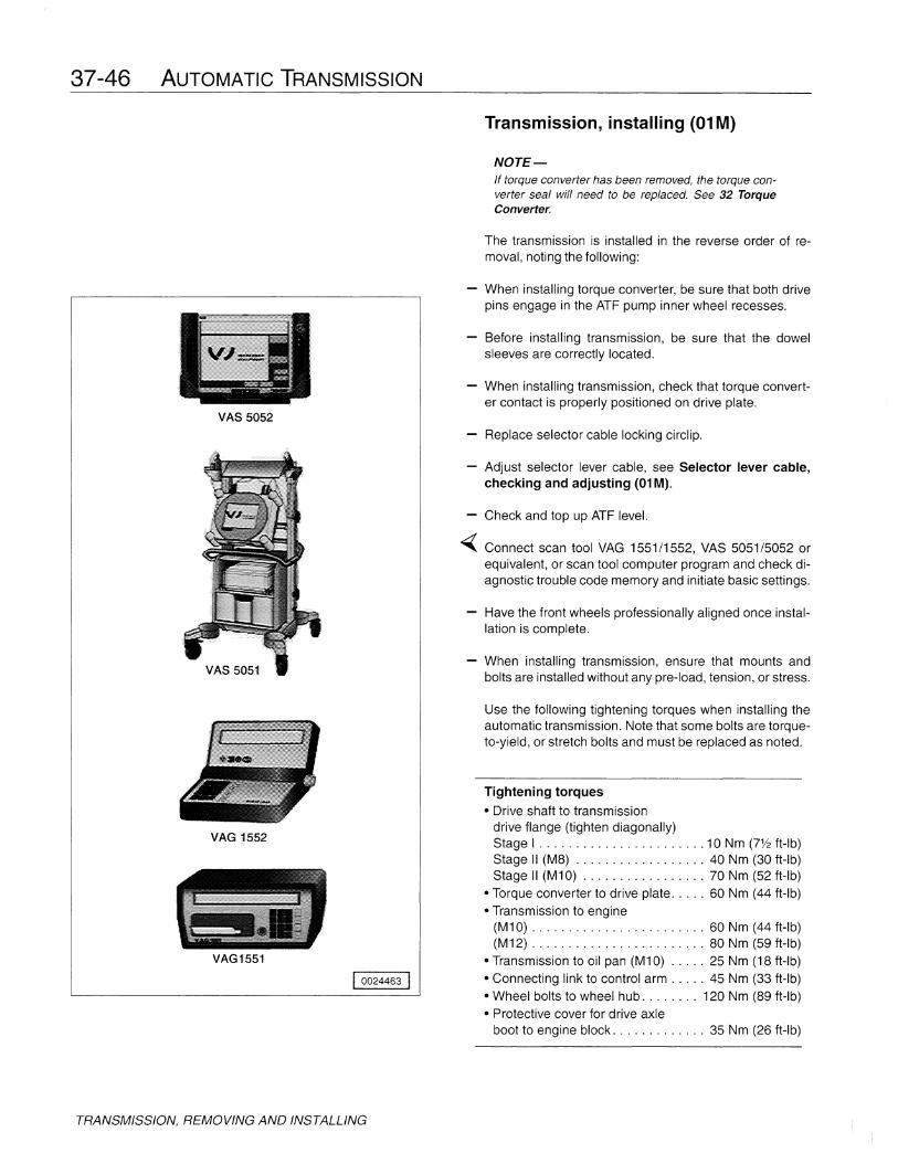
~ Connect scan tool VAG 1551/1552, VAS 5051/5052 orequivalent, or scan tool computer program and check diagnostic trouble code memory and initiate basic settings.
Have the front wheels professionally aligned once installation is complete.
When installing transmission, ensure that mounts andbolts are installed without any pre-load, tension, or stress.
Use the following tightening torques when installing theautomatic transmission. Note that some bolts are torqueto-yield, or stretch bolts and must be replaced as noted.
Tightening torques
• Drive shaft to transmissiondrive flange (tighten diagonally)Stage I 10 Nm (7112 ft-Ib)Stage II (M8) 40 Nm (30 ft-Ib)Stage II (M10) 70 Nm (52 ft-Ib)
• Torque converter to drive plate 60 Nm (44 ft-Ib)• Transmission to engine
(M10) 60 Nm (44 ft-Ib)(M12) 80 Nm (59 ft-Ib)
• Transmission to oil pan (M10) 25 Nm (18 ft-lb)• Connecting link to control arm 45 Nm (33 ft-Ib)• Wheel bolts to wheel hub 120 Nm (89 ft-Ib)• Protective cover for drive axle
boot to engine block 35 Nm (26 ft-Ib)
TRANSMISSION, REMOVING AND INSTALLING
AUTOMATIC TRANSMISSION 37-47
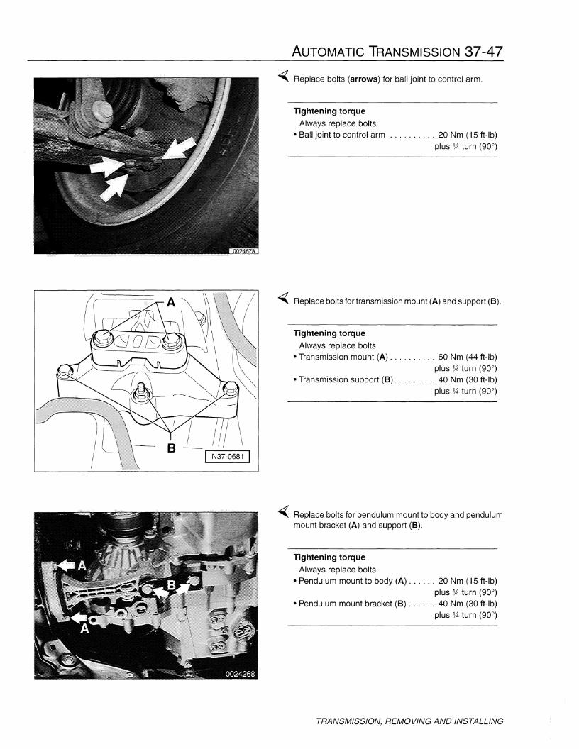
~ Replace bolts (arrows) for ball joint to control arm.
Tightening torque
Always replace bolts• Ball joint to control arm 20 Nm (15 ft-Ib)
plus 1A turn (90°)
~ Replace bolts for transmission mount (A) and support (B).
Tightening torque
Always replace bolts• Transmission mount (A) 60 Nm (44 ft-Ib)
plus 1A turn (90°)• Transmission support (B) 40 Nm (30 ft-Ib)
plus 1A turn (90°)
~ Replace bolts for pendulum mount to body and pendulummount bracket (A) and support (B).
Tightening torque
Always replace bolts• Pendulum mount to body (A) 20 Nm (15 ft-lb)
plus 1A turn (90°)• Pendulum mount bracket (B) 40 Nm (30 ft-Ib)
plus 1A turn (90°)
TRANSMISSION, REMOVING AND INSTALLING

37-48 AUTOMATIC TRANSMISSION
Transmission, removing (09A)
Before beginning removal, check to ensure that the required special tools or their equivalent are readily available and modified as noted.
Volkswagen recommended special tools (01M)
• 10-222A transmission support kit• 10-222N2 hooks• 10-222N3 supports• 10-222N8 support legs• 10-222N12 shackles• 3094 hose clamps• 3282 transmission support• 3282/32 adjustment plate• 3300A engine support• 3336 transmission lifting beam• VAG 1331 torque wrench• VAG 1332 torque wrench• VAG 1383A engine/transmission jack• V/175 socket• T10099 multi-point bit, 12 mm• T10099/1 multi-point bit, 14 mm• T10036 support rails
NOTE-Be sure to have the anti-theft radio code on hand beforedisconnecting the battery.
Place selector lever into the P position.
Remove engine cover.
TRANSMISSION, REMOVING AND INSTALLING
Disconnect battery ground (GND) strap from batterynegative (-) terminal. See the Cautions at the beginningof this repair group regarding battery disconnection.
Disconnect battery positive (+) cable and remove batteryand battery tray. See 27 Engine Electrical.
~ Remove intake air hose (1), and harness connector (2),from Mass Air Flow (MAF) Sensor.
- Remove vacuum hose (3) to air cleaner near MAF, whereequipped.
- Remove complete air cleaner housing assembly by unscrewing bolts (4) and (5).
I N37-0781 1/// ,/ \A"-"--'-......I
AUTOMATIC TRANSMISSION 37-49
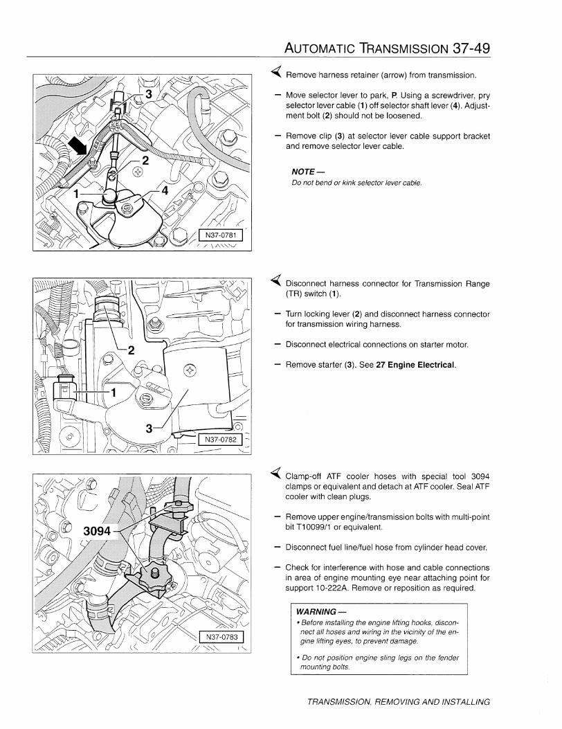
~ Remove harness retainer (arrow) from transmission.
Move selector lever to park, P. Using a screwdriver, pryselector lever cable (1) off selector shaft lever (4). Adjustment bolt (2) should not be loosened.
Remove clip (3) at selector lever cable support bracketand remove selector lever cable.
NOTE-00 not bend or kink selector lever cable.
~ Disconnect harness connector for Transmission Range(TR) switch (1).
- Turn locking lever (2) and disconnect harness connectorfor transmission wiring harness.
Disconnect electrical connections on starter motor.
Remove starter (3). See 27 Engine Electrical.
~ Clamp-off ATF cooler hoses with special tool 3094clamps or equivalent and detach at ATF cooler. Seal ATFcooler with clean plugs.
Remove upper engine/transmission bolts with multi-pointbit T10099/1 or equivalent.
Disconnect fuel line/fuel hose from cylinder head cover.
Check for interference with hose and cable connectionsin area of engine mounting eye near attaching point forsupport 10-222A. Remove or reposition as required.
WARNING-• Before installing the engine lifting hooks, disconnect all hoses and wiring in the vicinity of the engine lifting eyes, to prevent damage.
• 00 not position engine sling legs on the fendermounting bolts.
TRANSMISSION, REMOVING AND INSTALLING
37-50 AUTOMATIC TRANSMISSION
I N37-0674 I
TRANSMISSION, REMOVING AND INSTALLING
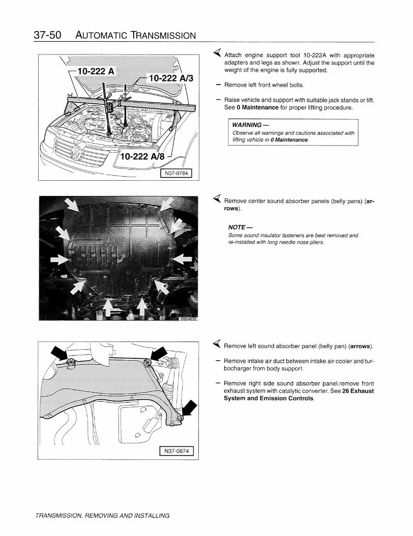
~ Attach engine support tool 10-222A with appropriateadapters and legs as shown. Adjust the support until theweight of the engine is fully supported.
Remove left front wheel bolts.
Raise vehicle and support with suitable jack stands or lift.See 0 Maintenance for proper lifting procedure.
WARNING-Observe all warnings and cautions associated withlifting vehicle in 0 Maintenance.
Remove center sound absorber panels (belly pans) (arrows).
NOTE-Some sound insulator fasteners are best removed andre-installed with long needle nose pliers.
~ Remove left sound absorber panel (belly pan) (arrows).
Remove intake air duct between intake air cooler and turbocharger from body support.
Remove right side sound absorber panel. remove frontexhaust system with catalytic converter. See 26 ExhaustSystem and Emission Controls.

N37-0785
I II
N37-0786 1-<
1 N40-0259 I
AUTOMATIC TRANSMISSION 37-51
~ Remove ground strap (1) from retainer on transmission.
- Remove power steering hydraulic line (2) from rear oftransmission (arrows).
Remove retainer (3).
Remove power steering hydraulic line from rear of transmission (in area of pendulum support) and secure (tie)out of the way with wire.
Remove retaining bracket from valve body cover.
Unbolt both drive shafts at transmission drive flangesand secure (tie) up as high as possible.
~ Remove lower rear engine/transmission securing bolt (A).
Remove access cap for torque converter nuts.
Remove torque converter nuts (arrow) (quantity 3) withspecial socket (V/175 or equivalent).
NOTE-Turn crankshaft 120 0 to access each nut.
Loosen retainer (B) for oil level/temperature sensor cableand turn to the side.
- Turn steering fully to left.
~ Mark installation position of ball joint bolts (arrows) onleft control arm and remove left control arm bolts.
TRANSMISSION, REMOVING AND INSTALLING
37-52 AUTOMATIC TRANSMISSION
TRANSMISSION, REMOVING AND INSTALLING
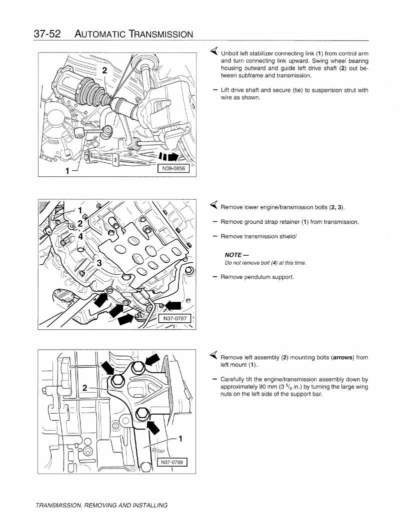
"'iiii( Unbolt left stabilizer connecting link (1) from control armand turn connecting link upward. Swing wheel bearinghousing outward and guide left drive shaft (2) out between subframe and transmission.
- Lift drive shaft and secure (tie) to suspension strut withwire as shown.
"'iiii( Remove lower engine/transmission bolts (2, 3).
- Remove ground strap retainer (1) from transmission.
- Remove transmission shield/
NOTE-Do not remove bolt (4) at this time.
- Remove pendulum support.
"'iiii( Remove left assembly (2) mounting bolts (arrows) fromleft mount (1).
- Carefully tilt the engine/transmission assembly down byapproximately 90 mm (3 5/ 8 in.) by turning the large wingnuts on the left side of the support bar.

A
I N37-0790 I
AUTOMATIC TRANSMISSION 37-53
~ Turn right side transmission drive flange (B) until the flatsection is vertical.
Bolt support rail T10036 to both pendulum support securing holes on subframe (A) and tighten.
Secure support 3300A to support rail T10036 with bolts(arrows) and extend to engine as shown.
Carefully push engine/transmission assembly forwardusing a wrench on end of threaded section of 3300A.
NOTE-Take care to avoid damage to power steering hydrauliclines when moving engine/transmission assembly.
~ Assemble transmission jack with transmission supportfixture 3282, 3282/32 adjustment plate (marked 09A),and support/clamping elements.
• Place adjustment plate 3282/32 on support fixture 3282noting that plate fits properly in one direction only andthat embossed arrow points to the front of the vehicle.
• Align arms of support fixture with holes in adjustmentplate and attach pins to arms as indicated on plate
• Symbols on plate (A, B) indicate type of clamps required.
NOTE-Arrow on adjustment plate 3282/32 must point towardfront of vehicle.
3282 I N37-0791 I
~ Place assembled transmission jack under transmission.
Align adjustment plate to transmission and lock safetysupports on transmission jack.
Secure transmission to support 3282 with bolt (A).
Remove engine/transmission bolt (arrow).
WARNING-Before unbolting lower engine-to-transmissionmounting bolts be sure to support the weight of thevehicle at all four corners with jack stands designedfor that purpose. Removal of the transmission canupset the weight balance of the vehicle and cause itto fall off the lift.
TRANSMISSION, REMOVING AND INSTALLING

37-54 AUTOMATIC TRANSMISSION
TRANSMISSION, REMOVING AND INSTALLING
<Separate transmission from engine while pushing torqueconverter away from drive plate (dashed arrow) so thatit stays within the transmission bell housing.
WARNING-The torque converter should come off with thetransmission. Secure the torque converter to thetransmission to prevent damage.
Lower transmission slightly.
NOTE-While lowering transmission, guide power steering hydraulic line past transmission.
Swing transmission towards subframe.
<Lower transmission carefully and guide right side driveflange shaft (A) in area of engine drive plate and left sidedrive flange (B) out past subframe.
NOTE-• While lowering transmission, use transmission support 3282 to change tilt angles.
• Secure torque converter to prevent it from falling out.
If transmission is to be replaced, unbolt (arrows) originalmount (A) and transfer to new unit.

~10-222A12
w~~~,~10-222A112J
I N37-0780 I
AUTOMATIC TRANSMISSION 37-55
Transmission, transporting (09A)
Due to size, bulk, and especially weight, the transmissionis best moved by fitting the lifting hooks, 10-222AJ2 and10-222AJ12. Use of this support in conjunction with a suitable shop crane will minimize the chance of damage tothe transmission.
<liiiii( Lift transmission with a suitable shop crane and transportto work area or shipping container to avoid personal injury and/or damage to transmission.
Transmission, installing (09A)
The transmission is installed in the reverse order of removal, noting the following:
Install torque converter.
<liiiii( The torque converter is installed correctly when the distance (a) between the transmission housing flange andthe machined contact surface for the securing studs is asspecified.
• 21 mm (0.827 in) for 4-cylinder engines• 17 mm (0.669 in) for 6-cylinder engines
If distance (a) is not correct, torque converter is not properly installed. Slide converter out and reposition until correct distance is obtained.
NOTE-When installing transmission into vehicle, be sure thattorque converter does not move. If torque converterslips out, installation distance may change and transmission can not be installed.
<liiiii( If transmission is to be replaced, unbolt (arrows) originalmount (A) and transfer to new unit.
Before installing transmission, be sure that the dowelsleeves are correctly located.
When installing transmission, check that torque converter contact is properly positioned on drive plate.
Replace selector cable locking circlip.
Adjust selector lever cable, see Selector lever cable,checking and adjusting (09A).
TRANSMISSION, REMOVING AND INSTALLING
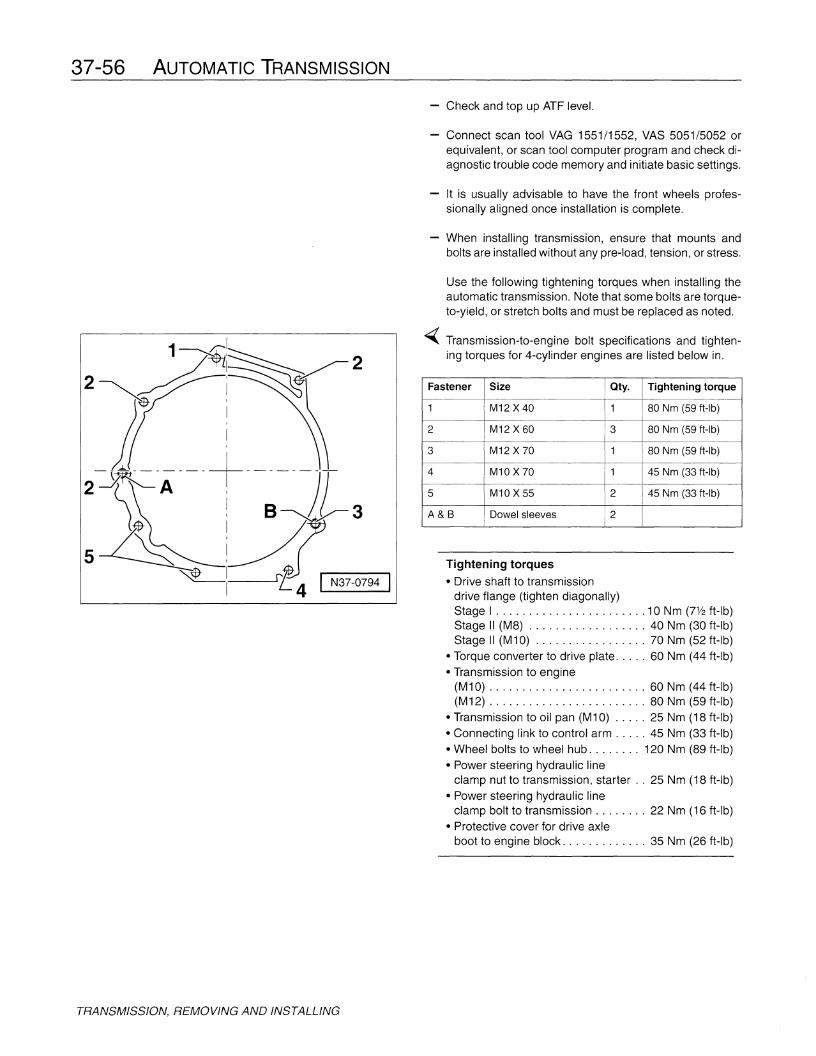
37-56 AUTOMATIC TRANSMISSION
- Check and top up ATF level.
- Connect scan tool VAG 1551/1552, VAS 5051/5052 orequivalent, or scan tool computer program and check diagnostic trouble code memory and initiate basic settings.
It is usually advisable to have the front wheels professionally aligned once installation is complete.
- When installing transmission, ensure that mounts andbolts are installed without any pre-load, tension, or stress.
Tightening torques
• Drive shaft to transmissiondrive flange (tighten diagonally)Stage I 10 Nm (7112 ft-Ib)Stage II (M8) 40 Nm (30 ft-Ib)Stage II (M10) 70 Nm (52 ft-Ib)
• Torque converter to drive plate 60 Nm (44 ft-Ib)• Transmission to engine
(M10) 60 Nm (44 ft-Ib)(M12) 80 Nm (59 ft-Ib)
• Transmission to oil pan (M10) 25 Nm (18 ft-Ib)• Connecting link to control arm 45 Nm (33 ft-Ib)• Wheel bolts to wheel hub 120 Nm (89 ft-Ib)• Power steering hydraulic line
clamp nut to transmission, starter .. 25 Nm (18 ft-lb)• Power steering hydraulic line
clamp bolt to transmission 22 Nm (16 ft-Ib)• Protective cover for drive axle
boot to engine block 35 Nm (26 ft-Ib)
Use the following tightening torques when installing theautomatic transmission. Note that some bolts are torqueto-yield, or stretch bolts and must be replaced as noted.
~ Transmission-to-engine bolt specifications and tightening torques for 4-cylinder engines are listed below in.
Fastener Size Qty. Tightening torque
1 M12 X 40 1 80 Nm (59 ft-lb)
2 M12 X 60 3 80 Nm (59 ft-Ib)
3 M12 X 70 1 80 Nm (59 ft-lb)
4 M10 X 70 1 45 Nm (33 ft-lb)
5 M10 X 55 2 45 Nm (33 ft-lb)
A&B Dowel sleeves 2
:Sl~: rt.4 I N37-0794 I
1~:~ 22 ~~'~~~ !
II
I
5
TRANSMISSION, REMOVING AND INSTALLING

AUTOMATIC TRANSMISSION 37-57
~ Replace bolts (arrows) for ball joint to control arm.
Tightening torque
Always replace bolts• Ball joint to control arm 20 Nm (15 ft-Ib)
plus % turn (90°)
~ Replace bolts (arrows) for transmission mount (1, 2).
Tightening torque
Always replace bolts• Transmission mount (arrows) ..... 50 Nm (37 tt-lb)
plus 1)+ turn (90°)
~ Replace bolts for pendulum mount to body and pendulummount bracket (A) and support (B).
Tightening torque
Always replace bolts• Pendulum mount to body (A) 20 Nm (15 ft-Ib)
plus 1)+ turn (90°)
• Pendulum mount bracket (B) 40 Nm (30 ft-Ib)plus 1)+ turn (90°)
TRANSMISSION, REMOVING AND INSTALLING

37-58 AUTOMATIC TRANSMISSION
ATFCOOLER
-( Replace bolts (arrows) for transmission mount (A) totransmission.
Tightening torque
Always replace bolts• Transmission mount (A) 50 Nm (37 ft-lb)
plus % turn (90°)
-( Torque bolts (arrows) for transmission shield in sequence (1,2,3,4).
Tightening torque
Torque in sequence• Transmission shield 22 Nm (16 ft-lb)
ATF COOLER
The 01M and 09A transmissions both use a cooler to control the temperature of the fluid. Hot, pressurized fluid issupplied to one section of the cooler. The heat is thentransferred to the engine coolant through the other section and dissipated through the radiator. The coolerworks in reverse when the engine and transmission arecold to help bring the ATF up to operating temperaturemore quickly.
If the vehicle has ATF in the cooling system, alwayscheck the ATF cooler. If the ATF shows evidence of engine coolant contamination, also check the cooler for internal leakage. Engine coolant contamination of the ATFwill result in serious internal transmission problems, particularly with the friction materials.

ATF cooler (01M)
1. Banjo bolts
• Hollow bolts• Tighten to 35 Nm (26 ft-lb)
2. O-ring, upper• Always replace
3. ATF cooler• See Removing• See Installing
4. O-ring, lower• Always replace
5. Transmission housing
6. Seal• Always replace
7. Sealing/level plug
8. Cap• To secure ATF sealing/level
plug after checking ATF level• Always replace
9. ATF filler tube
10. O-ring• Always replace
11. Location of transmission codeand production numbers
AUTOMATIC TRANSMISSION 37-59
~ Removing
• Clamp-off ATF cooler hoses withspecial tool 3094 clamps orequivalent and detach at ATFcooler.
• Seal ATF cooler with clean plugs.• Remove banjo bolts (arrows) and
lift cooler out.- Installing
• Install in reverse order.• Always replace O-rings.
ATFCOOLER

37-60 AUTOMATIC TRANSMISSION
ATF cooler (09A)
1. Transmission housing
2. O-ring, large• Always replace
3. ATFcooler• See Removing• See Installing
4. Special bolt• Tighten to 40 Nm (35 ft-Ib)
5. Dished washer• When properly installed, outer
circumference touches washer,item 6 below.
6. Washer
7. O-Ring• Always replace
~4I ~5
~6cb~T 7~
I____ .J
N37-0798
~ Removing
• Remove air cleaner assembly.• Clamp-off ATF cooler hoses with
special tool 3094 clamps or equivanlent.
• Detach hoses at ATF cooler.• Seal ATF cooler with clean plugs.• Remove center special bolt and
lift cooler out.
ATFCOOLER
~ Installing
• Install in reverse order.• Always replace O-rings.• Install cooler (1) so that locating
tab aligns with slot in transmission housing (B).
• Torque special bolt (A) to specification.
I N37-0799 I