automatic robotic spray painting of low volume high ... · pdf fileproceedings of the 33rd isr...
TRANSCRIPT

Proceedings of the 33rd ISR (International Symposium on Robotics) October 7 – 11, 2002
Automatic Robotic Spray Painting ofLow Volume High Variant Parts
M. Vincze, A. Pichler, G. Biegelbauer K. Häusler e-mail: {vm,ap,gb}@infa.tuwien.ac.at, e-mail: [email protected], Automation and Control Institute ACIN Profactor Produktionsforschungs GmbH Vienna University of Technology 4400 Steyr, Austria 1040 Vienna, Austria
H. Andersen, O. Madsen, M. Kristiansene-mail: {henrik,i9om,morten}@iprod.auc.dk
Department of Production, University of Aalborg9220 Aalborg, Denmark
ABSTRACTWith the advance in IT technology sensors andprocessing power exist to achieve fully automatedrobot programming in industrial tasks. This paperreports on the EU-project FlexPaint, which devised amethodology to automatically generate robotprograms for spray painting of unknown parts. Thesolution uses four steps: laser triangulation sensing,geometric feature detection, tool path planning, andthe generation of the collision-free executable robotprogram. Demonstrations at industrial partners showthe results.Keywords Automated robot programming, featuredetection, path generation, collision avoidance, spraypainting.
1 INTRODUCTIONThe objective of the European RTD project FlexPaint(www.flexpaint.org) is to automate robot pro-gramming for painting applications of small lot sizeswith a very high number of part variants. Presentlyrobotic painting is economically feasible for large lotsizes, since a robot program needs to be established(using off-line programming and/or manual teach-in)for each single part variant. The project goal is toprovide economic possibilities for usage of robots inpainting of large part families (e.g., see Figure 1).The goal is to reduce human programming effort by75 percent and the human spray painting effort by 90percent.
The technical challenge is to develop a method thatcan fulfil the spray painting task similar to a humanpainter, who is able to paint a geometry never seenbefore. A possible solution is to utilize CAD data tocalculate a paint path and to measure the actual partlocation. However, 3D CAD data is often not fullyavailable and hence this approach is limited to fewapplications. Within FlexPaint an "inverse approach"is developed, which does not require any CAD data.
Figure 1: Examples of a part family of gearboxeswith motor and a close-up of one of the parts, acompressor tank, a steering column and other smallparts in a frame. Parts are represented in roughlycorrect relative size.
The procedure is to automatically obtain robotic paintpaths from range sensor data and to automaticallygenerate a feasible, complete and executable robotprogram. The approach copes with a large spectrumof parts such as motors with gears, small parts onframes (car mirrors, plates, pipes, etc.), or largecompressor tanks. For each industrial customer thepart families (comprising up to 70.000 variants) areknown (Figure 1). The goal is to be able to paint anyorder of parts coming along the conveyor. Thetechnical challenge is to detect the geometry of thepart on the conveyor, to automatically infer from the

Proceedings of the 33rd ISR (International Symposium on Robotics) October 7 – 11, 2002
geometry the robotic painting trajectory and toautomatically generate a collision-free robot program.
1.1 Related WorkRelated work is the automatic generation of a 3Dpaint path, which has been attempted in theSmartPainter project. The painting motion wasgenerated by virtually folding out the surfaces to bepainted, putting on the painting motion and foldingback the surfaces and letting the painting motionsfollowing this folding of surfaces [1, 7]. However,this strategy is only applicable when 3D models ofthe objects are available and the curvature of theobjects is relatively small. The patented technologyfrom Advanced Robotics Technologies uses a 2Ddigital photo as input [US patent no. US 5,429,682].The user decides on the screen where to apply paintstrokes. The path planning for a robot is then doneautomatically.
First approaches to obtain an automatic tool path in3D are known from milling turbine blades byconsidering planar cross sections [4, 10] or using agrid cell approach [11].
2 FLEXPAINT APPROACHThe FlexPaint approach is based on the observationthat the parts comprise a large number of elementarygeometries with typical characteristics for an entireproduct family. Examples are rib-sections (coolingribs), cylindrical surfaces (typical for motors), andcavities (typical for hollow structures or constructionsto obtain stiffness). Another type of surface is forexample the surfaces of a rear view mirror. Thesesurfaces are smooth free-form surfaces, which arevery difficult to represent by use of simple geometricattributes such as cylinders, spheres and boxes.Relying on elementary geometries the technical goalbecomes to specify these elementary geometries insuch a way that generic methods for detection and forpath planning can be developed and that the varietyof geometries seen in the applications isencompassed.
The specification of elementary geometry types isbased on the observed part geometries and on theconstraints of the painting process. The idea is todetect elementary geometries that can be linked to aspecific process model, that is a model for thepainting process of this elementary geometry. Forexample, the geometry "flat surface" can be paintedwith a simple pattern of straight paint strokes. Morecomplex geometric shapes, such as cavities or ribs,need specific painting strategies: spraying into thecavity and painting parallel to the rib orientation,respectively.
The elementary geometry types are defined in theGeometry Library and related to the processknowledge, which is specified in the Procedure
Library. The complete FlexPaint approach is shownin Figure 2. The next sections will outline its maincomponents.
Figure 2: Block diagram of the FlexPaint system.
2.1 Part Measurement with Laser Trian-gulation Sensor
When the parts move along a conveyor, a laser rangesensing device scans the parts and obtains a 3Dmeasurement of point data of the object. The scansare triggered by the actual part motion of theconveyor (see Figure 3). For a part size of one metera resolution of better than one millimeter is obtained.Up to 700 scans per second are taken. This isobtained with a calibration as shown in Figure 4.
Figure 3: Schematic drawing of part measurementusing the sheet of light system of IVP, Sweden.
Often several parts are mounted on frames or skids.In this case a scan of the frame/skid is taken andsubtracted from the final image. Figure 5 shows anexample for a part measured with frame and the partdata automatically extracted. For every part detectedall other processing steps are performed individually.Finally, if parts are close to each other, larger robotpainting motions are obtained by painting severalparts with one stroke.

Proceedings of the 33rd ISR (International Symposium on Robotics) October 7 – 11, 2002
Figure 4: Set-up at ABB with the calibration box.
Figure 5: Original depth image of part and frame(top) and the extracted part (bottom).
2.2 FeatureFinderThe FeatureFinder developed by ACIN has the taskof detecting the part geometry using the geometricdefinitions of the geometry library. The output is adescription of the scanned part surface usingelementary geometries.FeatureFinder detects three classes of features, whichare relevant for the painting process: free-formsurfaces, cavities and rib sections. Classical rangeimage processing typically starts from segmentation(see e.g., a comparison in [2]). Finding features isthen constrained to defined geometric properties suchas planes or conics [6, 9].
The specific geometry of the three classes of featuresis not known, attributes (lower than surrounding rim,parallel ribs) define the feature. Hence, a genericapproach to feature detection is required.Figure 6 summarizes the developed image processingprocedure. The calibrated images which aresegmented into single parts are taken and the threeelementary features are detected with specific
procedures, which will be shortly outlined below.Details can be found in [8].
Figure 6: Block diagram of the FeatureFinder and itsimage processing procedures.
First cavities and ribs are detected. All remainingsurface parts are considered free-form surfaces.
A cavity is defined as a region where surface pointsare locally lower (in the sense of an outward surfacenormal) than a surrounding rim. The challenge is todevelop a robust procedure to handle noise andshadows of the range data.
The rim of the cavity is detected with an accuracy inthe range of the resolution. By using interpolationpoints the discovered cavities also include potentialareas of sensor shadow. This is important to detectthe full cavity region for the painting process. Thecavity is then represented as a mesh that covers theopening of the cavity. Figure 7 shows the meshrepresentation of the complete part. The opening ofthe cavities are represented as dark mesh. The meshrepresentation also has the advantage that it allowssignificant data reduction to render automatedgeneration of the painting trajectory fast.
Figure 7: The opening of the cavities are detectedautomatically and marked dark. The opening as wellas the remaining range image data is shown as mesh.Cavity detection for these examples is executed inabout ten seconds.
Proceedings of the 33rd ISR (International Symposium on Robotics) October 7 – 11, 2002
Figure 7 indicates a drawback of the noise tolerantmethod. The final mesh has difficulties representingsharp corners and the very narrow rim (3 pixels)between the two cavities of the sockets. However, amethod to better triangulate concave regions isalready in development.
A rib section is defined by a minimal number ofequidistant parallel lines. After edge detection theoriginal line segments are grouped into longer linesusing collinearity, proximity and overlap [3, 5]. Thelines are grouped using parallelism. Finally, a featurevector (distance, overlap, length, number of lines) ofall line groups is generated and used for classifyingrib sections. Figure 8 gives an example of a groupingresult.
Figure 8: Line segments and lines extracted from rawdata using grouping techniques.
2.3 PaintPlannerIn the next process step the painting trajectory for thespray gun is calculated for each of the elementarygeometries. Neighbouring paint strokes are fused toobtain longer and smoother trajectories. The finalresult is a complete paint path for the spray gun.
The module "Generate Painting Trajectory", shown inFigure 2, specifies a trajectory of the spray gun,which satisfies the desired paint quality. In thismodule only spray gun motions are considered inrelation to process quality. No restrictions of robotsare made and collisions between the spray gun and itssurroundings are not considered. The module uses theGeometry Library and the Procedure Library in orderto plan this trajectory. The Geometry Libraryspecifies for each geometric primitive one or morepainting procedures, which may be applied forpainting that particular type of geometric primitive.The painting procedure specifies how to apply spraygun motions to the surfaces in order to achieve asatisfactory process quality. The Procedure Library isestablished through experimental work.
The basic idea is to enable planning of paint strokesthat continue throughout the parts even thoughdifferent geometric primitives must be covered along
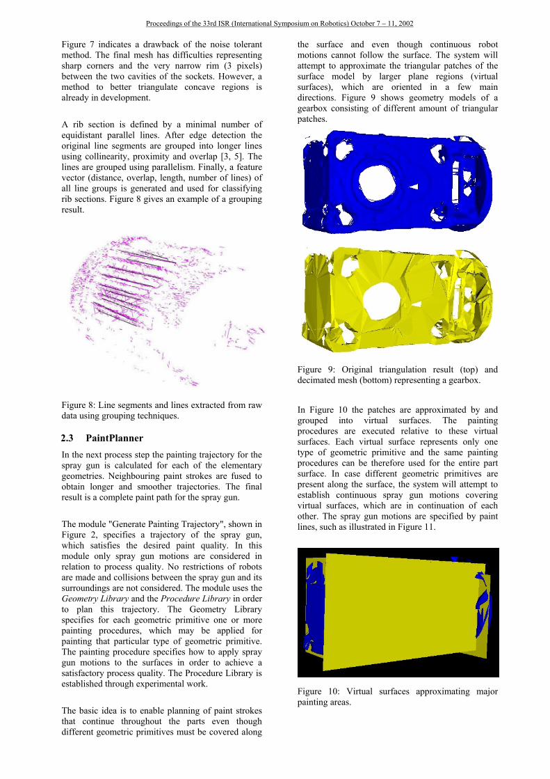
the surface and even though continuous robotmotions cannot follow the surface. The system willattempt to approximate the triangular patches of thesurface model by larger plane regions (virtualsurfaces), which are oriented in a few maindirections. Figure 9 shows geometry models of agearbox consisting of different amount of triangularpatches.
Figure 9: Original triangulation result (top) anddecimated mesh (bottom) representing a gearbox.
In Figure 10 the patches are approximated by andgrouped into virtual surfaces. The paintingprocedures are executed relative to these virtualsurfaces. Each virtual surface represents only onetype of geometric primitive and the same paintingprocedures can be therefore used for the entire partsurface. In case different geometric primitives arepresent along the surface, the system will attempt toestablish continuous spray gun motions coveringvirtual surfaces, which are in continuation of eachother. The spray gun motions are specified by paintlines, such as illustrated in Figure 11.
Figure 10: Virtual surfaces approximating majorpainting areas.

Proceedings of the 33rd ISR (International Symposium on Robotics) October 7 – 11, 2002
Figure 11: The painting strokes represented by lines.
From this and Figure 10 it can be seen that the paintlines follow the directions and the plane positions ofthe virtual surfaces. The painting procedure specifieshow many strokes the spray gun must make along thepaint line and which painting parameters are appliedin each of these strokes.
2.4 Automatic Generation of Collision-FreeRobot Programs
Next collision-free robot motion is established basedon the tool trajectory obtained from the PaintPlanner(see Figure 2). The actual paint trajectories arecalculated for a given robot manipulator. TheToolPlanner software from AMROSE Robotics ApS,is utilized for generating collision-free motions. Thistool has been customized for the FlexPaint projectand checks if any collisions occur between the robotand its surroundings. It uses a simplified solid model(a convex hull approximation) of the part to includethe workpiece into collision avoidance. Thissimplified geometry model, frame and paint paths areshown in Figure 12.
Figure 12: Simplified geometry model of a steeringcolumn, the frame (vertical bars) and paint paths withspray nozzle orientation.
Finally, the off-line programming systemRobotStudio from ABB converts the collision-freerobot trajectory into an executable robot program (seeFigure 13). RobotStudio internally utilizes a virtualcontroller of any ABB robot, hence, the physicalrobot will execute the program just as it is simulatedon the computer.
Figure 13: Simulation of the collision-free robotmotion.
3 EXPERIMENTAL RESULTSThe system is already implemented as a prototypeand has been tested in ABB's technical center inEichen, Germany (see Figure 4). The purpose of theseexperiments was to prove the basic system concept. Itwas realized that process quality has to be optimizedby establishing validated painting procedures for theindividual geometric primitives. The paintingprocedures used were not established by precedingexperiments. Since the surface was scanned onlyfrom one side of the part it was only possible toperform automatic spray painting of the scannedsurface. However, it was observed that a relativelygood painting quality was achieved on these parts ofthe surfaces, which were scanned. Figure 14 showsthe robot executing automatically generatedprograms.
Figure 14: The robot painting a steering column and agearbox with automatically generated programs.

Proceedings of the 33rd ISR (International Symposium on Robotics) October 7 – 11, 2002
The prototype installation demonstrated to be capableof realizing production constraints: (1) any series ofparts of the industrial parts shown in Figure 1 can bescanned. And, (2) the motion of the conveyor requiresan overall processing time of about 60 seconds.Range image processing requires about 30 seconds ona standard PC and path planning can also be executedin 30 seconds on a high end PC.
4 CONCLUSION AND OUTLOOKAn approach to automatically spray paint families ofunknown parts has been presented. The approach usesa sensing cell in front of the painting cell, where thepart geometry is acquired. From the part geometryprocess-relevant features are extracted andcorresponding paint routines are found and groupedto obtain optimal painting trajectories. Finally acollision-free robot path and an executable robotprogram are generated.
All steps are fully automatic and no intervention of anoperator is needed. The individual tools(FeatureFinder, PathPlanner, ToolPlanner) exist inprototype versions. First implementations at industrialusers show that the approach is feasible. Parts can bescanned and robot programs are generatedautomatically for a part rate of one per minute usingconventional PC technology.
At present only convex parts can be paintedautomatically, though L-shaped objects are alsopossible. Complex concave shapes, such as the truckchassis in Figure 15 are not possible.
It is planned to improve the FlexPaint process byusing robot-mounted sensors to be able to scansections of parts that are not visible with fixedsensors. Another extension will be methods to "teach"other than the existing geometric features.
Figure 15: Robotic painting of a complete truckchassis.
Even though the project is primarily aimed towardsrobotic spray painting, the "inverse approach"proposed can be applied for obtaining processmotions for a large range of processes in the field of
surface treatment. Examples of processes in whichthe approach is intended to be applied are: powderpainting, washing and cleaning with liquid (includinghigh-pressure cleaning), washing and cleaning withphysical contact between tool and part, degreasing,sandblasting, polishing, sealing, grinding, deburringand gluing.
REFERENCES[1] Hertling, P., Hog, L., Larsen, L., Perram, J.W.,
Petersen, H.G.: Task Curve Planning for PaintingRobots - Part I: Process Modeling andCalibration; IEEE Transactions on Robotics andAutomation 12(2), April 1996, 324-330.
[2] Hoover, A., et.al.: An experimental comparisonof range image segmentation algorithms; IEEETransactions on Pattern Analysis and MachineIntelligence 18(7), 1-17, 1996.
[3] Iqbal, Q., Aggarwal, J.K.: Applying perceptualgrouping to content-based image retrieval:Building images, IEEE International Conferenceon Computer Vision and Pattern Recognition,Fort Collins, Colorado, Vol. 1, pp. 42--48, 1999.
[4] Kwok, K.S., Louks, C.S., Driessen, B.J.: Rapid3-D Digitizing and Tool Path Generation forComplex Shapes; IEEE International Conferenceon Robotics and Automation, 2789-2794, 1998.
[5] Lowe, D.G.: Three-Dimensional Object Recogni-tion from Single Two-Dimensional Images;Artificial Intelligence 31(3), 355-395, 1987.
[6] Marshall, D.; Lukacs, G.; Martin, R.: Robustsegmentation of primitives from range data in thepresence of geometric degeneracy; IEEETransactions on Pattern Analysis and MachineIntelligence 23(3), 304 -314, 2001.
[7] Olsen, M.M., Petersen, H.G.A: A new methodfor estimating parameters of a dynamic robotmodel; IEEE Transactions on Robotics andAutomation 17(1), 95 -100, 2001.
[8] Pichler, A., Vincze, M.: Cavity and RibDetection in Range Images for AutomatedRobotic Spray Painting of Lot Size One; IROS2002, submitted.
[9] Robertson, C., Fisher, R.B., Werghi, N.,Ashbrook, A.P.: Finding Machined Artifacts inComplex Range Data Surfaces, Proc. ACDM2000, Plymouth, UK, Springer LNCS, 2000.
[10] Sheng, X., Krömker, M.: Surface Reconstructionand Extrapolation from Multiple Range Imagesfor Automatic Turbine Blades Repair; IEEEIECON Conference Vol. 3, 1315-1320, 1998.
[11] Tse, W.C., Chen, Y.H.: A robotic system forrapid prototyping, IEEE International Conferenceon Robotics and Automation Vol.3, 1815 -1820,1997.