automatic presser-foot force control for industrial sewing...
TRANSCRIPT

Automatic presser-foot force control for industrial sewing machines
Abstract
Purpose To develop and test control methods for real-time automatic presser-foot force control in industrial sewing machines. In this work, a closed-loop controller that controls presser-foot maximum vertical displacement is presented and compared to existing solutions that adjust force depending on sewing speed. Automatic force control can reduce problems such as stitch irregularity, stitch distortions and material damage, besides making material handling easier. Design/methodology/approach An electromagnetic force actuator was integrated in an industrial lockstitch machine. A computer-based control system was designed implementing either speed-variable force control, closed-loop control, or emulating a traditional constant-force system. Maximum presser-foot displacement values were measured and analysed in relevant sewing situations, and seam quality was assessed. Findings Constant-force control does not allow optimal force setting at all speeds. Speed-variable force control is an improvement, but requires empirical setting of the speed-force relation, not always assuring optimal operation. Closed-loop control adapts force to the requirement of each sewing situation more precisely. Sewing quality is good and material handling is eased. Research limitations/implications The actuator has to be optimised regarding response time and maximum force. Some aspects in the behaviour of the control system and actuator have to be further studied. Practical implications The proposed control system enables the automatic setting and adaptation of force to all sewing situations, making material handling easier at low speeds without compromising feeding performance at high speed. The closed-loop controller may be used as teach-in system for speed-dependent control. Originality/value This is the first prototype of a closed-loop control system for presser-foot force on a lockstitch sewing machine and the first comparative study of control methods for presser-foot force control.

Keywords
presser-foot force control, closed-loop control, electromagnetically actuated presser-
foot, fabric feeding system, sewing process, controller teach-in
Paper type: Technical Paper

1 Introduction and Objectives
1.1 Introduction
Clear and precise knowledge of the sewing process, as well as tools to control and
optimise machine functions are increasingly important in the sewing industry. On one
hand, the traditional garment production faces ever higher requirements on product
quality, manufacturing flexibility and lower set-up times for reduced time-to-market.
On the other hand, technical textiles impose tighter tolerances often associated to safety
issues, for which a higher level of control of the processes is required.
However, due to difficulties in collecting understandable data, to interpret the
interdependence of each parameter, and to various technological issues, no major
advances in this regard have resulted in the last decades.
This paper is focused on one of the most important functions involved in the process -
fabric feeding - specifically addressed to the feeding system of an industrial lockstitch
sewing machine (Figure 1) and deals with the design and development of a closed-loop
presser-foot controller. The objective of this controller is to provide the presser-foot
with the exact force needed to ensure constant contact with the sewn fabrics in all
situations. Control is performed in real-time, on a stitch-by-stitch basis.

Figure 1. Basic drop-feed fabric feeding system.
1.2 Literature review
Several researchers have studied the effect of the feeding system set-up on seam quality,
in some cases with instrumented sewing machines to measure some of the sewing
parameters, including the variables more directly related to the material feeding process:
force on the presser-foot and presser-foot vertical displacement.
The first studies on seam quality can be accredited to Dorkin and Chamberlain (1961).
Their work analyses the relation of seam pucker occurrence with the behaviour of the
feeding system. The operation of the feeding system is described in a very detailed way.

Based on this work, Johnson (1974) developed experiments and presented a
mathematical model for the movement of the presser-foot in a sewing machine. Johnson
was particularly concerned on predicting the contact losses between presser-foot and
feed-dogs, concluding that contact losses increase with sewing speed and decrease when
presser-foot pre-tension is increased.
Further work on presser-foot “bouncing” was produced by Frank and Mo (1974), who
applied a pneumatic actuator to a Union Special lockstitch machine.
Mende (1982) presented a more complete model to describe presser-foot movement and
force that confirmed and refined the conclusions drawn by Johnson , Frank and Mo.
Matthews and Little (1988) equipped a sewing machine with sensors to measure force
on the needle and presser-foot bars. Their studies focused mainly on the feeding system,
and the results reported by Johnson, Frank and Mo, and Mende, were again
experimentally confirmed.
Barrett (1992) materialized the previous results into the concept of an active actuation
system for the presser-foot, called “autodamp”, which used an electromagnetic actuator
with a “maglev” presser-foot controller proposed by Barrett and Clapp (1995, 1996).
The main objective of the set-up was to maintain constant force between the presser-
foot and the fabric.
Chmielowiec and Lloyd (1995) equipped a Pfaff lockstitch machine with sensors
measuring presser-foot force and displacement, thread tension and needle penetration
force. They were able to detect the effect of “presser-foot bouncing”.

Amirbayat et al. (1995, 1996) studied the performance of the feeding system by
measuring vertical presser-foot displacement with a contactless arrangement using a
Hall-effect sensor.
Stylios et al. (1990, 1992, 1995a, 1995b, 1996) analysed several aspects of “intelligent
garment manufacturing”. In these studies, both the organizational as well as the
technical aspects of sewing process control were discussed. The concept of “the
Sewability Integrated Environment” was introduced. Lockstitch and overedge sewing
machines were equipped with sensors measuring sewing speed, thread tension, tension
disk, presser-foot and feed-dog pressures, and differential feed setting. Stepper motors
were used to adjust thread tensions, and a pneumatic actuator allowed setting the force
on the presser-foot. An extensive experiment with a variety of fabric types was carried
out and a neuro-fuzzy control system was designed and trained to adjust presser-foot
pressure and thread tensions. The system took as inputs a fabric sewability factor
computed on basis of material parameters, and sewing speed. Reported results were
very interesting.
Rocha et al (1996) equipped an overedge sewing machine with sensors to measure
several sewing parameters, amongst which presser-foot force. The phenomenon of
presser-foot bouncing could also be detected on the force signals.
Silva (2002), extensively analysed the relation between presser-foot force,
displacement, sewing speed, material properties and the resulting sewing problems.
1.3 Problem definition

The drop-feed systems found on several types of sewing machines basically comprise
three components: a presser foot, a throat plate and a feed dog (figure 1). The throat
plate is a smooth surface that supports the fabric being sewn with openings for the
needle and the feed dog to pass. The presser foot, with a helical spring working under
compression in the presser-foot bar, is responsible for guaranteeing the required
pressure to control fabrics feeding and to constrain their movement during needle
penetration and withdrawal. The feed dog, made up by teethed elements, is used to
move the fabrics a certain desired distance (called stitch length) between needle
penetrations. During its movement, the feed dog rises above the throat plate to engage
the fabric against the underside of the presser foot before starting the advancing motion.
Some of the problems in the sewing process, which results in an irregular stitch
formation and other sewing defects, rely on the interaction between the presser-foot and
the feed dog. The drop-feed system is the most simple and inexpensive system of all. It
is not adequate for sewing elastic materials, that are stretched during feeding. In this
case, a differential bottom feed is used, normally found on overedge, interlock and
chainstitch sewing machines. Other feeding systems combine the drop-feed (simple or
differential) with a feeding presser-foot and needle feed. These are used to work with
heavier materials, and can virtually eliminate the problems of ply-shift. However, the
problem of adequate presser-foot force adjustment is present in all of these systems.
It is common knowledge in the sewing industry that the setting of presser-foot force can
never be chosen optimally for every sewing situation. Low presser-foot force, for
instance, favours material handling and reduces damage on the fabric. However, it will
cause problems at higher speed, in which loss of contact between fabric and presser-
foot, and phenomena such as “presser-foot bouncing” produce stitch irregularities which
are an obvious functional and aesthetical defect in a seam.

Silva et al. (2002, 2003) performed extensive experimentation on an overedge machine
with a standard presser-foot system, equipped with a helical compression spring. In
these experiments, Silva observed irregularity of stitch length according to materials,
sewing speed and presser-foot force settings. During these experiments, signals of
vertical presser-foot displacement (Figure 1) were acquired. Figure 2 shows the typical
waveforms at two different sewing speeds. The acquired signals were processed
dividing the waveform of each stitch in two phases: Phase 1 – fabric feeding, and phase
2 – needle penetration and withdrawal/stitch formation. The peak displacement values
in these phases were then computed.
Figure 2. Typical presser-foot displacement curves at two different sewing speeds: 2000 and 4700
spm (stitches per minute): Phase 1 – fabric feeding; phase 2 – needle penetration and
withdrawal/stitch formation. The image shows two stitch cycles.

It has been has found that both peaks tend to increase with sewing speed and this
increase can be related to presser-foot bouncing and in consequence the loss of contact
between the presser-foot and the fabrics (Silva, 2002). Increasing the force on the
presser-foot in this situation avoids the contact losses, reducing both displacement
peaks. It was also observed that presser-foot bouncing is worse with thinner fabrics,
because thicker fabrics provide some damping to the impact between feed dog and
presser-foot. For this reason, in theory, presser-foot force has to be higher when
working with thinner fabrics; however, this represents a problem, because thinner
fabrics are generally more sensitive to damage.
To improve the feeding process, in a first phase an electromagnetically actuated presser-
foot (using a proportional force solenoid) was designed and integrated into the overegde
machine. Force applied on the presser-foot was then varied according to the sewing
conditions (Silva, 2002), and more elaborate control systems were tested (Silva et al.,
2003, 2004a, 2004b, 2010). It was shown that a control system aiming to maintain the
main presser-foot displacement peak within a pre-determined value resulted in good
seam quality, with regular stitch length and reduced ply-shift.
The only system currently commercially available that tackles the problems relating to
fabric feeding with variable speed is the PFAFF SRP (Speed-Responsive Presser-foot).
In this system, the pre-tension of the spring that exerts force on the presser-foot is
varied dynamically by displacing a linear motor. This is an advance over traditional
machines, in which presser-foot pre-tension is set mechanically and remains constant.
Nevertheless, the system lacks a quantitative method of determining the ideal force for
each sewing speed. The speed-force curve is set according to subjective evaluation of
the sewing technician.

The system presented in this paper is also different from the previous work by Stylios et
al (1995b, 1996) in several aspects. The most important difference is the presser-foot
displacement feedback, which allows monitoring the process and allows a closed-loop
control of the process itself, in real time, given that presser-foot displacement reflects
the state of the process directly. Another difference is that the tests to determine
material parameters and thus the sewability factor are unnecessary, a simple sewing test
is sufficient for adjustment of the system. Finally, in the current work a proportional
force-solenoid is used instead of the pneumatic actuator. This type of actuator provides
much simpler, linear control and in principle allows faster actuation, which is important
at sharp sewing speed variations, common in daily operation.
1.4 Purpose and objectives of this study
The objective of this study is to transpose Silva’s approach to a lockstitch machine and
perform a more extensive study by testing a broader range of sewing situations and
compare the system’s performance using three different approaches: i) constant force on
the presser-foot, ii) speed-variable force (feedforward control) and iii) closed-loop
(feedback) control of force using presser-foot vertical displacement. Moreover, and
specifically regarding closed-loop control, another objective is to test automated
methods to define the controller references.
The closed-loop control system uses the presser-foot maximum vertical displacement as
feedback variable. The aim is to keep this value within limits, on one hand assuring that
there is no excessive compression of the fabrics, and on the other hand maintaining the
presser-foot in contact with the fabrics at higher speeds, by increasing force on the
presser-foot. In this way, regular material feeding is assured, thus reducing problems

such as stitch length irregularity, ply shift, seam distortions at sharp speed variations
and material damage by excessive presser-foot force. Moreover, it allows lower
presser-foot force at low speed, easing material handling (e.g. turning) for the operator.
An additional benefit of the displacement measurement feedback is the possibility of
detecting defects, such as folds, wrinkles, wrong number of fabric plies or misalignment
of the fabric plies.
Finally, it would make the adjustment of the machines much easier, quicker and much
more objective, eliminating the trial-and-error methods generally employed. This is
especially important considering the current trend of apparel manufacture: small order
quantities and ever increasing material and style variety.
2 System Set-up
Figure 3 shows the set-up of the hardware on a Zoje lockstitch machine. The controller
uses a Schaevitz model DC-EC 250 LVDT for displacement measurement and a
Wandfluh PI60V proportional force solenoid with Wandfluh P02 proportional-amplifier
as current driver.
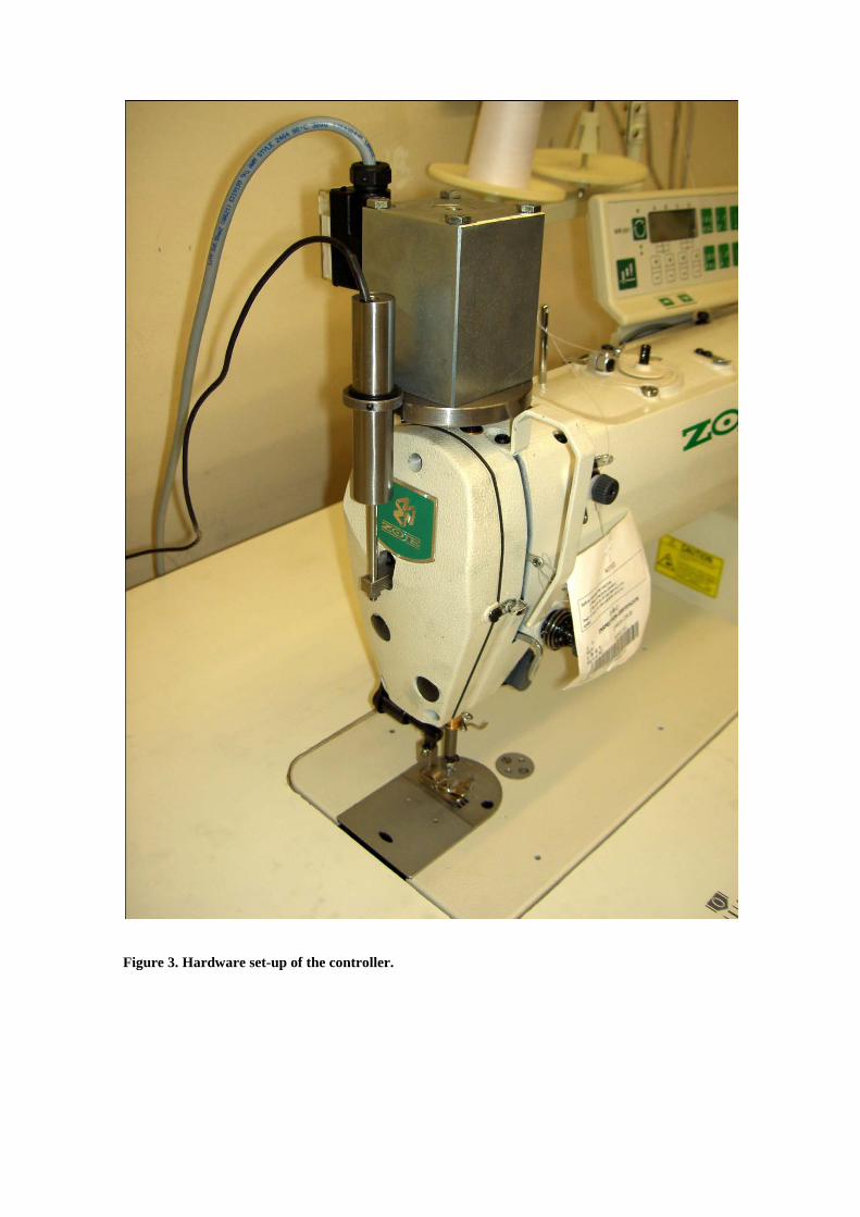
Figure 3. Hardware set-up of the controller.

The proportional force solenoid was chosen instead of another type of actuator because
of its straightforward force control, since force is proportional to the input current over a
wide range of stroke. The Wandfluh PI60 presents a rated maximum force of 65 N, a
maximum stroke of 6 mm (with proportional force behaviour assured up to 3 mm) and a
step response time of about 50 ms. The response time is not stated on the datasheet; the
value has been conveyed by the manufacturer. This value is a fundamental parameter to
consider. It measures the time the actuator needs between 10% and 90% of the final
output value after a very fast (stepwise) change in the input current. Considering that the
sewing machine has a maximum speed of 4000 stitches per minute, each stitch takes
about 15 ms, which means that the actuator is only able to converge to the final desired
value after a little more than 3 stitches. Some problems at sharp speed variations may be
anticipated due to this. Still, this type of actuators is one of the fastest available,
adequate for a proof-of-concept.
Preliminary experiments showed, however, poor results using the force solenoid
coupled directly to the presser-foot bar, such that the set-up was modified to include a
spring. The actuator would thus vary pre-tension of the spring, similarly to PFAFF’s
SRP system. In this configuration, the actuator is able to produce a maximum force of
about 33 N (computed on basis of the maximum stroke of the actuator and the spring
constant).
A PC was equipped with a National Instruments PCI-6251 data acquisition board and
software to control the system was developed in Labview (Figure 4). Labview has been
selected as development tool for its outstanding flexibility in the development of the
controller prototype.

The developed software implements three different types of force control: Constant
force, speed-dependent force (open-loop or feedforward control) or closed-loop
(feedback) control of the presser-foot vertical displacement. During machine operation
the values of force (calculated), presser-foot displacement and sewing speed (acquired)
are displayed (Figure 4). Controller parameters can be changed for experimentation.

Figure 4. Control software general view

3 Controller Design
3.1 Constant Force
In this case the force is set up as a constant value, reproducing the mode of operation of
a regular industrial sewing machine.
3.2 Speed-dependent control
This mode emulates the operation of the Pfaff SRP system. The force on the presser-
foot is set as a function of speed (Figure 5). A 4th-order polynomial was used to
implement the speed-force function (the feedforward map).
Figure 5. Speed-dependent open-loop control implemented according to the speed-variable force
control curve example presented in Figure 7.
3.3 PID closed-loop control
In the new proposed solution, the force applied to the fabric is varied depending on the
error computed between the measured maximum presser foot displacement values and
the reference value (Figure 6).

Figure 6. Closed-loop control block diagram.
The PID control is implemented on basis of Labview’s PID control toolkit as follows
(National Instruments, 2006).
The current displacement error is computed according to equation 1:
𝑒(𝑘) = 𝑅𝑒𝑓 − 𝐷𝑖𝑠𝑝 (1)
with
e(k) : Displacement error in stitch k
Ref : Displacement reference
Disp : Measured maximum displacement
Based on this error, the algorithm calculates the proportional (equation 2), integral
(equation 3) and partial derivative action (equation 4) of the controller as
𝑂𝑃(𝑘) = 𝐾𝑝 ∗ 𝑒(𝑘) (2)
𝑂𝐼(𝑘) = 𝐾𝑝𝑇𝑖∑ �𝑒(𝑖)+𝑒(𝑖−1)
2�𝑘
𝑖=1 ∆𝑡 (3)
𝑂𝐷(𝑘) = −𝐾𝑝𝑇𝑑
[(𝐷𝑖𝑠𝑝 (𝑘) − 𝐷𝑖𝑠𝑝 (𝑘 − 1)] (4)
with
OP: Proportional action output
kp: Controller gain
OI : Integral action output
Ti : Integral time, in minutes
OD : Proportional action output
Td : Derivative time, in minutes
The output of the controller is the sum of the three actions:
𝑂(𝑘) = 𝑂𝑃(𝑘) + 𝑂𝐼(𝑘) + 𝑂𝐷(𝑘)
with
O: Total controller output, in Volt (actuator force control signal)
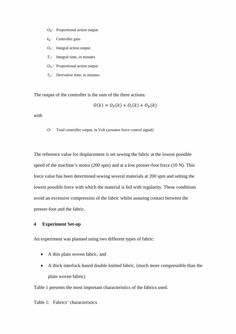
The reference value for displacement is set sewing the fabric at the lowest possible
speed of the machine’s motor (200 spm) and at a low presser-foot force (10 N). This
force value has been determined sewing several materials at 200 spm and setting the
lowest possible force with which the material is fed with regularity. These conditions
avoid an excessive compression of the fabric whilst assuring contact between the
presser-foot and the fabric.
4 Experiment Set-up
An experiment was planned using two different types of fabric:
• A thin plain woven fabric, and
• A thick interlock-based double knitted fabric, (much more compressible than the
plain woven fabric)
Table 1 presents the most important characteristics of the fabrics used.
Table 1: Fabrics’ characteristics
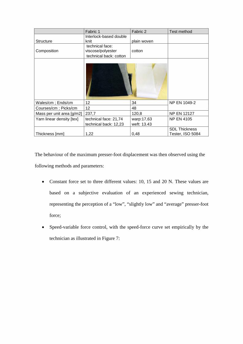
Fabric 1 Fabric 2 Test method
Structure Interlock-based double knit plain woven
Composition
technical face: viscose/polyester cotton
technical back: cotton
Wales/cm ; Ends/cm 12 34 NP EN 1049-2 Courses/cm ; Picks/cm 12 48
Mass per unit area [g/m2] 237,7 120,8 NP EN 12127 Yarn linear density [tex] technical face: 21,74 warp:17,63 NP EN 4105
technical back: 12,23 weft: 13.43
Thickness [mm] 1,22 0,48
SDL Thickness Tester, ISO 5084
The behaviour of the maximum presser-foot displacement was then observed using the
following methods and parameters:
• Constant force set to three different values: 10, 15 and 20 N. These values are
based on a subjective evaluation of an experienced sewing technician,
representing the perception of a “low”, “slightly low” and “average” presser-foot
force;
• Speed-variable force control, with the speed-force curve set empirically by the
technician as illustrated in Figure 7:

Figure 7. Speed-variable force control curve.
• PID closed loop force control with the following parameters:
Proportional gain kp= 1.44;
Integral time Ti =0,05 min, and
Derivative time Td=0,001 min.
A first approach to the PID settings was obtained using the Ziegler-Nichols method.
The values were then tuned to assure a compromise between the system’s behaviour at
the different sewing speeds for the two fabrics. As expected, the ideal values were
dependent on the fabric type and on sewing speed, but it was possible to find a set-up
assuring adequate operation in all of the analysed situations (except low-speed
operation, as will be seen later).
The references were defined as 1.05 mm for the woven fabric and 1.42 mm for the
knitted fabric.
The following sewing situations were then produced:

• Gradual increase of speed up to 4000 spm;
• Sharp speed variations between 1000 and 3000 spm. The reason why 3000 spm
was used instead of 4000 spm will be explained later.
Results were then evaluated considering:
• The maximum displacement values for each situation;
• The ability of the system to maintain the references defined, and
• The system response to sharp speed variations.
An additional evaluation was made analyzing the ply-shift produced. For this purpose,
two plies of fabric 50 cm long were sewn with the ends exactly aligned. The seam was
performed without any influence of the operator besides holding the fabrics gently to let
the fabric be fed by the machine. The resulting ply-shift was then evaluated measuring
the misalignment of the sewn fabric plies at the seam end.
5 Results
The experiment generated a large set of data, the most significant of which will be
herein presented.

5.1 Constant force
Figure 8 shows the results obtained for the plain woven fabric. The reference
displacement value defined for this fabric was 1.05 mm.
Figure 8. Presser-foot displacement measured on the plain woven fabric with constant force, speed
varying gradually from 0 to 4000 spm, and presser-foot forces of 10 N (upper graph), 15 N (middle
graph) and 20 N (lower graph).

As can be observed, the constant force setting does not meet the requirements of sewing
at variable speed. At 20 N presser-foot force it is possible to notice that force is
excessive at low speeds (displacement much lower than the reference, fabric
compressed) whilst still not enough at higher speeds (displacement higher than the
reference, possible contact losses).
5.2 Speed-variable force control
Figure 9 shows the result of a gradual increase of speed using the speed-dependent force
controller.
Figure 9. Presser-foot displacement measured on plain woven fabric with speed-variable force
control. Presser-foot maximum displacement (upper graph), presser-foot force (middle graph) and
sewing speed (lower graph).
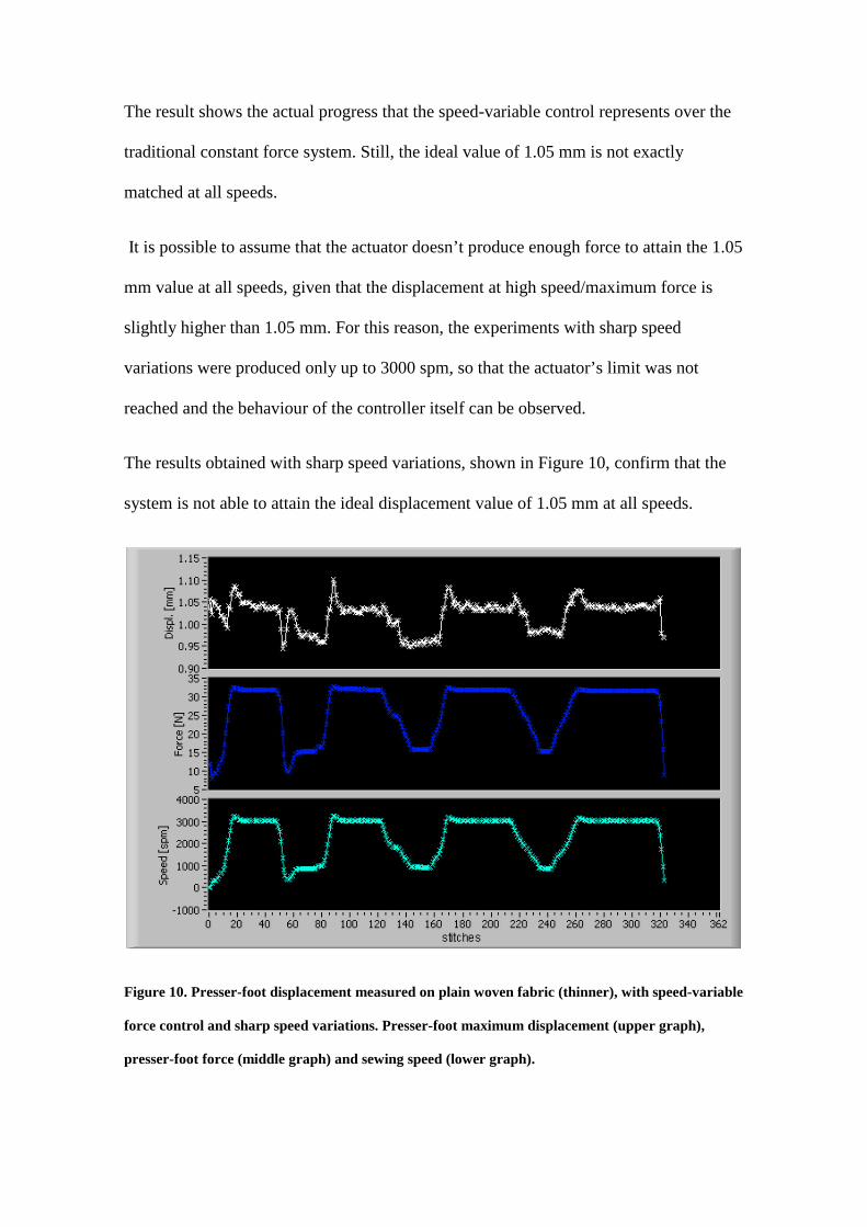
The result shows the actual progress that the speed-variable control represents over the
traditional constant force system. Still, the ideal value of 1.05 mm is not exactly
matched at all speeds.
It is possible to assume that the actuator doesn’t produce enough force to attain the 1.05
mm value at all speeds, given that the displacement at high speed/maximum force is
slightly higher than 1.05 mm. For this reason, the experiments with sharp speed
variations were produced only up to 3000 spm, so that the actuator’s limit was not
reached and the behaviour of the controller itself can be observed.
The results obtained with sharp speed variations, shown in Figure 10, confirm that the
system is not able to attain the ideal displacement value of 1.05 mm at all speeds.
Figure 10. Presser-foot displacement measured on plain woven fabric (thinner), with speed-variable
force control and sharp speed variations. Presser-foot maximum displacement (upper graph),
presser-foot force (middle graph) and sewing speed (lower graph).

It is possible to see that the system exerts excessive force at low speeds (compressing
the fabric below 1.05 mm), but at 3000 spm it is able to approximate this reference.
Nevertheless, the displacement variation is very low. The system takes about 5 stitches
to converge to the final displacement value, due to the actuator’s response time. In fact,
at 3000 spm, each stitch takes about 20 ms, meaning that the actuator’s step response
may be slightly higher than the 50ms specified.
5.3 PID closed-loop force control
The behaviour of the system with increasing speed on the plain woven fabric (Figure
11) shows that the actuating system does not produce enough force to maintain the
displacement reference of 1.05 mm at all speeds. Maximum force is produced at about
2500 spm and up to that point the system is able to maintain the reference.
Figure 11. Presser-foot displacement measured on plain woven fabric, with PID force control.
Presser-foot maximum displacement (upper graph), presser-foot Force (middle graph) and sewing
speed (lower graph).

As expected, the behaviour of the system is better when sewing the thicker fabric
(Figure 12). In this case the ideal displacement defined was 1.42 mm.
Figure 12. Presser-foot displacement measured on knitted fabric with PID force control. Presser-
foot maximum displacement (upper graph), presser-foot force (middle graph) and sewing speed
(lower graph).
In both situations the controller evidences slight instability at low speed, at which the
force is switched between two values.
Sharp speed variations have been produced between 1000 and 3000 spm on the plain
woven (thinner) fabric. The results in Figure 13 show that the control system is able to
converge to the defined reference after about 5 stitches, which should correspond to the
actuator’s response time. In fact, it is higher than the 50 ms specified (5 stitches @ 3000
spm correspond to 100 ms).
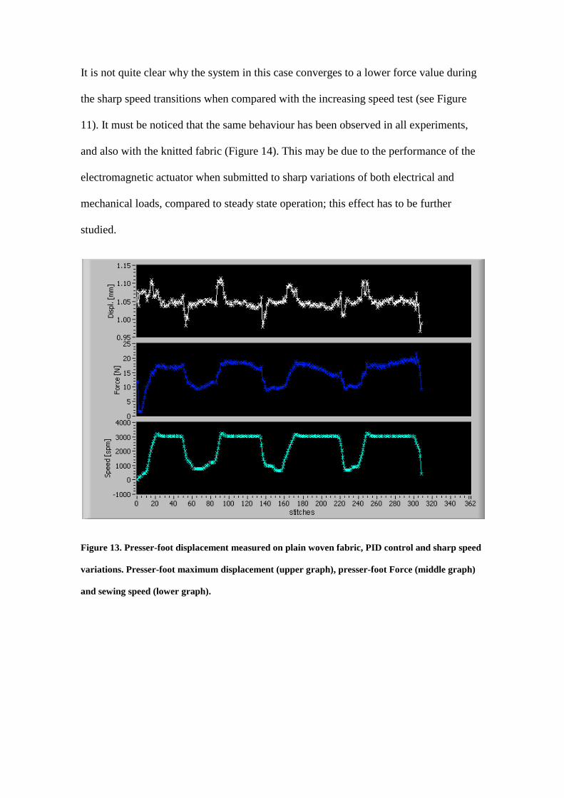
It is not quite clear why the system in this case converges to a lower force value during
the sharp speed transitions when compared with the increasing speed test (see Figure
11). It must be noticed that the same behaviour has been observed in all experiments,
and also with the knitted fabric (Figure 14). This may be due to the performance of the
electromagnetic actuator when submitted to sharp variations of both electrical and
mechanical loads, compared to steady state operation; this effect has to be further
studied.
Figure 13. Presser-foot displacement measured on plain woven fabric, PID control and sharp speed
variations. Presser-foot maximum displacement (upper graph), presser-foot Force (middle graph)
and sewing speed (lower graph).

Figure 14. Presser-foot displacement measured on knitted fabric, with PID control and sharp speed
variations. Presser-foot maximum displacement (upper graph), presser-foot force (middle graph)
and sewing speed (lower graph).
5.4 Seam quality results
Ply-shift evaluation was used to assess the effect of the controller’s performance on
seam quality. Results showed that ply-shift ranged from 1mm (0,2%) up to 12 mm
(2,4%) on the 50 cm long seams that were produced, and is approximately proportional
to the presser-foot force.
At constant force, low force settings reduce ply-shift, but the system is unable to control
the fabric at high speeds. In this situation, the stitch length exhibits a clearly visible
reduction, especially during sharp speed transitions. Higher forces can produce more
damage on the fabric and impede proper handling of the fabrics.

The samples sewn with sharp speed variations using the PID control were inspected at
the locations of the seam where the speed variations occurred, and no particular
difference in stitch length or any other defect were observed, despite the delay in
actuation shown in the measured displacement values.
In the speed-variable and PID force controls, ply-shift is dependent on sewing speed. It
was observed that the seams produced with these two types of force control are more
even at all speeds and that handling of the fabrics is much easier due to force reduction
at low speeds. The PID controller produced the most regular seams; however, the
difference observed in seam quality between variable-speed and closed-loop controls is
not significant, if compared to the major improvement attained by both systems over the
constant-force approach.
6 Discussion of Results
According to all testing conditions and obtained results, the speed-variable force control
and PID force control techniques presented the best results in terms of sewing
performance, when compared with the constant force actuation. The PID controller
demonstrated a more precise force adjustment to every situation.
Based on the visual inspection of the sewn samples and on the ply-shift evaluation
carried out, both types of force control present a major advantage, especially at lower
speeds, whilst maintaining normal operation at higher speeds. The stitch length also
showed to be more regular considering the whole speed range. In the particular situation
of sharp speed transitions that generally produces some kind of local distortion of the
seam (stitch length variations, folds), both systems performed better than the traditional
spring-based system.

In general, it can be said that the two approaches present the best compromise between
ease of handling and seam quality at low speeds without sacrificing performance at high
speed.
The efficiency of the speed-variable force control, however, depends mainly on the
correct adjustment of the speed-force relationship. From this point of view, the PID
controller presents a clear advantage. Measurement of presser-foot displacement
waveforms in this system also enables process monitoring, i.e. the detection of defects.
On the other hand, the PID control is technically more complex.
An interesting solution would be the combination of both approaches: A speed-variable
force controller on the machine, programmed by a “teach-in” programming device
based on the PID controller. For this purpose, sewing speed would be varied from
minimum to maximum and the PID loop would determine the force necessary to
maintain a certain reference. This external programming device would be connected to
the machine when necessary and would also allow the remote setting of the speed-force
function on other, similar machines.
7 Future work
Further research work has to be undertaken to implement adjustment of PID parameters
to speed, in order to correct low-speed instability. However, as these also depend on
fabrics characteristics, autotuning systems will be considered. It has to be determined if
the PID controller settings are applicable to a wide range of materials, or if the
controller should be tuned for each material for maximum performance. This would be a
drawback for the solution if it can not be done automatically. In this case the use of the
PID controller as teach-in device is suggested. For teach-in, the response time of the
control system is not important, it is just important that the system converges to a force

value for a range of sewing speeds, providing the optimal the speed-force curve to be
use in the speed-dependent control. However, it has to be said that in this work two very
different materials were tested, and the controller performed well on both of them
(except at low speed).
Another aspect to analyse in further detail is the actuator performance and possibly
actuator selection itself. The behaviour of the actuator during sharp speed variations has
to be analysed and optimised in terms of step response time and effects produced by
quickly varying mechanical load.
Tests have to be carried out to check if it is really necessary to maintain the reference
established or if a tolerance can be considered, especially at high speeds, since an
excessive presser-foot force may cause other sewing defects.
Finally, the system should be adapted to and tested on machines with other types of
feeding systems, such as combined drop-feed with upper feeding.
8 Concluding Remarks
This paper summarizes the latest developments and contributions to the development of
new sewing machines capable to set-up automatically and to self-adjust to the required
operation settings during the sewing process.
A scientific understanding of the feeding process, to improve sewing machine design
and performance, has been achieved and an electromagnetically actuated presser-foot
solution has been presented, to equip an industrial lockstitch sewing machine. Two
control strategies have been presented and adopted, based on the use of a feedforward
control and a feedback control. Both controllers perform well, being a major progress

when compared to traditional systems. The seam quality evaluation also reflects this
good performance, for all testing speeds and conditions.
The proposed control systems represent a further step towards a more knowledgeable
adjustment of the machines.
Acknowledgements
This research work was co-funded by Zoje Sewing Machine Co.,Ltd and is a follow-up
from a research project previously funded by FCT (Fundação para a Ciência e
Tecnologia- POSI/SRI/38944/2001 )
References
Dorkin, M., Chamberlain N (1961), “Seam Pucker: Its Cause and Prevention”,
Clothing Institute, Technological Report No. 10
Johnson, E. (1973) Some Factors Affecting the Performance of High Speed Sewing
Machines. Clothing Research Journal, Vol. 1, No. 1, pp. 3-35.
Frank, T., Mo, E. (1974), “A Simple Test for Assessing Presser Foot Bounce”, Clothing
Research Journal, Vol. 2, No. 2, pp. 81-84, 1974.
Mende, S. (1982), “ Untersuchung des Zusammenwirkens von Transporteur / Nähgut /
Nähfuß / Stichplatte bei Industrienähmaschinen”, Textiltechnik, 32 (5), pp. 291-294,
Matthews, B. N. , Little, T. (1988), “Sewing Dynamics, Part I: Measuring Sewing
Machine Forces at High Speeds”, Textile Research Journal, 58, pp. 383-391.

Barrett, G. (1992), “ Sewing Dynamics: The Autodamp Technology for the Elimination
of Presser Foot Bounce”, North Carolina State University Leaflet, 7/92
Barrett, G., Clapp, T. (1995), “Coprime Factorization Design of a Novel Maglev Presser
Foot Controller”, Mechatronics Journal, Vol. 5, No. 2/3, Elsevier Science Ltd, pp. 279-
294
Barrett, G., Clapp, T. (1996), “Sewing machine having presser bar system for
maintaining constant contact force between presser foot and fabric”, United States
Patent 5551361
Chmielowiec, R., Lloyd, D. (1995), “The Measurement of Dynamic Effects in
Commercial Sewing Machines”, Proceedings of The 3rd Asian Textile Conference, Vol.
II, pp. 814-828
Amirbayat, J., Alagha, M., Porat, I. (1995), “Factors Affected by Machine Settings and
Fabric Properties in Knitwear Production Part I: Seam Shrinkage and Thread
Consumption”, Journal of the Textile Institute 86, No. 1, pp. 110-118
Amirbayat, J., Alagha, M., Porat, I. (1996), “Study of Positive Needle Thread Feed
During Chainstitch Sewing”, Journal of the Textile Institute 87 Part 1, No. 2, pp. 389-
395, 1996.
Stylios, G. (1990), “Prognosis of Sewability Problems in Garment Manufacture Using
Computer Based Techniques”, Proceedings of the IEEE International Conference on
Systems Engineering 9-11 August, Pittsburgh, PA, USA
Stylios, G., Fan, J., Sotomi, J., Deacon, R. (1992), “Introducing a New Concept in
Garment Manufacture, The Sewability Integrated Environment Incorporating Automatic

Objective Measurement Systems”, 2nd International Clothing Conference, July, 1992
and International Journal of Clothing Science and Technology. Vol. 4 No 4
Stylios, G., Sotomi, J., Zhu, R., Xu, Y., Deacon, R. (1995), “The Mechatronic
Principles for Intelligent Sewing Environments”, Mechatronics Journal Vol. 5, No.
2/3, Elsevier Science Ltd, pp. 309-319
Stylios, G., Sotomi, J. (1995), “A Neuro-fuzzy Control System for Intelligent Overlock
Sewing Machines”, International Journal of Clothing Science and Technology Vol. 7,
No. 2/3, pp. 49-55
Stylios, G. (1996), “The Principles of Intelligent Textile and Garment Manufacturing
Systems”, Assembly Automation Vol. 16, No. 3, pp. 40-44
Rocha, A.M., Lima, M.F., Ferreira, F.N., Araújo, M.D. (1996), “Developments in
Automatic Control of Sewing Parameters”, Textile Research Journal, 66, 4, (p251-256)
Silva, L.F. (2002), “Estudo de Mecanismos Alternativos de Controlo do Sistema de
Alimentação de Máquinas de Costura Industriais”, PhD Thesis, School of Engineering,
University of Minho, Guimarães, Portugal, retrieved September 20th from
http://hdl.handle.net/1822/37
Silva, L.F., Lima, M., Carvalho, H., Rocha, A., Ferreira, F., Monteiro, J., Couto, C.
(2003), “Actuation, Monitoring and Closed-loop Control of Sewing Machine Presser
Foot”, Transactions of the Institute of Measurement and Control Vol. 25(5), Arnold
Journals, UK, pp. 419-432.
Silva, L.F., Carvalho, H., Soares, F. (2004), “Improving Feeding Efficiency of a Sewing
Machine by On-Line Control of the Presser Foot”, Proceedings of the 4th International

Conference on Advanced Engineering Design – AED’2004, University of Glasgow,
Glasgow, Scotland, UK, 5-8 September 2004.
Guhr, F., Silva, L.F., Soares, F., Carvalho, H. (2004), “Fuzzy Logic Based Control
Strategies for an Electromagnetic Actuated Sewing Machine Presser Foot”, Proceedings
of the IEEE ICIT’2004 – International Conference on Industrial Technology, December
8-10, 2004, Hammamet, Tunisia.
Carvalho, H., Rocha, A., Monteiro, J., Silva, L.F. (2003), “Planning, Control and
Monitoring Tools for Industrial Garment Assembly Processes”, Proceedings of the
IEEE International Conference on Industrial Technology, pp 381-386, Maribor,
Slovenia, 10-12 December 2003
Silva, L.F., Carvalho, H. , Soares, F., Guhr, F. (2010), “Adaptive Control of an
Electromagnetically Actuated Presser-Foot for Industrial Sewing”, 15th IEEE
International Conference on Emerging Technologies and Factory Automation, Faculty
of Engineering of The University of the Basque Country, Bilbao, Spain, 13-16
September
National Instruments Corporation , “LabVIEW PID Control Toolkit User Manual” , 2006