automatic line coloring (alc) - topology
TRANSCRIPT

zenon manual Automatic Line Coloring
(ALC) - Topology
v.8.20

© 2020 Ing. Punzenberger COPA-DATA GmbH
All rights reserved.
Distribution and/or reproduction of this document or parts thereof in any form are permitted solely
with the written permission of the company COPA-DATA. Technical data is only used for product
description and are not guaranteed properties in the legal sense. Subject to change, technical or
otherwise.

Contents
1 Welcome to COPA-DATA help ............................................................................................................... 5
2 Automatic Line Coloring (ALC) - Topology ......................................................................................... 5
3 ALC elements ............................................................................................................................................... 6
3.1 Procedural elements via Combined element .........................................................................................8
3.1.1 Switch example - colors from ALC ................................................................................................................. 14
3.1.2 Connection points of procedural elements ................................................................................................ 17
3.1.3 Switch input/output ............................................................................................................................................. 19
3.1.4 Measuring points .................................................................................................................................................. 20
3.2 Lines .................................................................................................................................................................... 21
3.2.1 Example ..................................................................................................................................................................... 25
3.2.2 Connection points of lines ................................................................................................................................ 26
3.3 Checking the project .................................................................................................................................... 27
4 Configuration ............................................................................................................................................ 28
4.1 Configuration of the sources ..................................................................................................................... 29
4.1.1 Coloring mode for UNDEFINED ...................................................................................................................... 33
4.2 Configuration of topological interlockings .......................................................................................... 34
4.2.1 Disconnector under load - interlocking conditions ................................................................................ 38
4.3 Configuration of the screen marker........................................................................................................ 40
5 Function: Change ALC source color ..................................................................................................... 41
6 Alias for detail screens ............................................................................................................................ 43
7 Fault locating in electric grids ............................................................................................................... 45
7.1 Search for ground fault ............................................................................................................................... 47
7.1.1 Mode of the search for ground faults .......................................................................................................... 48
7.1.2 Ground fault detection type ............................................................................................................................. 49
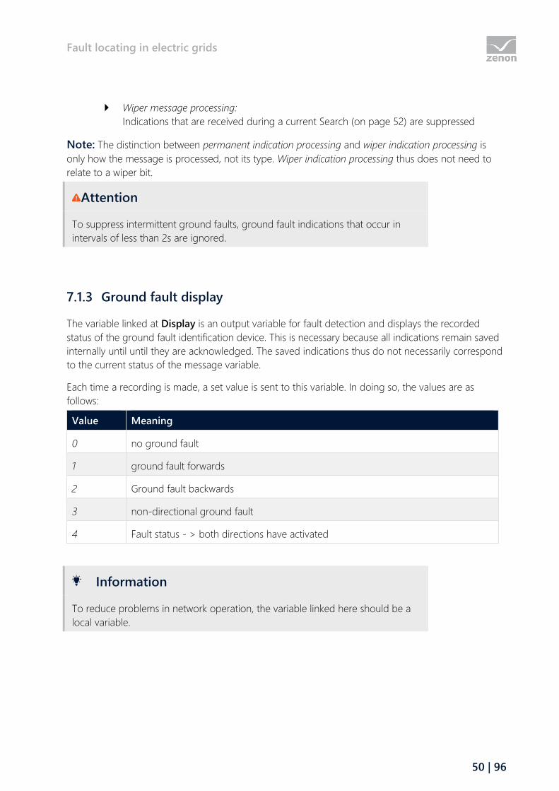
7.1.3 Ground fault display ............................................................................................................................................ 50
7.1.4 Earth fault triggering ........................................................................................................................................... 51
7.1.5 Start search for ground fault ............................................................................................................................ 52
7.1.6 Acknowledge ground fault indication .......................................................................................................... 53
7.1.7 Stop search for ground fault ............................................................................................................................ 54
7.2 Short circuit search ........................................................................................................................................ 54
7.2.1 Short-circuit recognition type .......................................................................................................................... 55
7.2.2 Ground fault display ............................................................................................................................................ 56
7.2.3 Ground fault detection triggering .................................................................................................................. 56
7.2.4 Acknowledge short-circuit message ............................................................................................................. 57
7.3 Curb..................................................................................................................................................................... 58
8 Impedance-based fault locating and load distribution calculation ............................................ 60
8.1 Impedance-based fault locating of the short circuit ........................................................................ 61
8.2 Load distribution calculation ..................................................................................................................... 62
8.3 Expanded topological model .................................................................................................................... 63
8.4 API ....................................................................................................................................................................... 64
9 Load flow calculation .............................................................................................................................. 66
9.1 General ............................................................................................................................................................... 66
9.2 Requirements .................................................................................................................................................. 68
9.3 Engineering in the Editor ............................................................................................................................ 68
9.3.1 Transformers ........................................................................................................................................................... 70
9.3.2 Configuration of the load flow output parameters ................................................................................. 73
9.4 Screen type Load flow (n-1) calculation ................................................................................................ 74
9.4.1 Engineering in the Editor ................................................................................................................................... 78
9.5 Screen switching for the load flow (n-1) calculation ........................................................................ 78
9.5.1 Load flow calculation screen switching filter ............................................................................................. 80
9.5.2 Column selection................................................................................................................................................... 81
9.5.3 Column format ....................................................................................................................................................... 82
9.6 Operation in Runtime ................................................................................................................................... 85
9.6.1 Topologic interlockings ...................................................................................................................................... 86
9.6.2 View in zenon Runtime ....................................................................................................................................... 87
9.7 Calculation ........................................................................................................................................................ 87
9.7.1 Busbars and branches ......................................................................................................................................... 88
9.7.2 Calculation of the electrical sizes .................................................................................................................... 89
9.7.3 Parallel lines ............................................................................................................................................................. 89
9.7.4 Transformers ........................................................................................................................................................... 90
9.7.5 Capacitors ................................................................................................................................................................ 91
9.8 Warning messages and LOG entries ...................................................................................................... 91
10 State Estimator.......................................................................................................................................... 94
10.1 Engineering in the Editor ............................................................................................................................ 95

Welcome to COPA-DATA help
5 | 96
1 Welcome to COPA-DATA help
ZENON VIDEO TUTORIALS
You can find practical examples for project configuration with zenon in our YouTube channel
(https://www.copadata.com/tutorial_menu). The tutorials are grouped according to topics and give an
initial insight into working with different zenon modules. All tutorials are available in English.
GENERAL HELP
If you cannot find any information you require in this help chapter or can think of anything that you
would like added, please send an email to [email protected].
PROJECT SUPPORT
You can receive support for any real project you may have from our customer service team, which
you can contact via email at [email protected].
LICENSES AND MODULES
If you find that you need other modules or licenses, our staff will be happy to help you. Email
2 Automatic Line Coloring (ALC) - Topology
The topological coloring of lines allows easy automatic dynamizing of tubes in technology (for media)
as well as in the energy distribution (for electricity). So process controlled coloring of topological nets
can easily be realized.
Because the tube structure is designed in the screen with all its technological elements (e.g. tanks and
valves, or generators, switches and consumers), it is internally emulated as a model and the media
flow is displayed in the Runtime.

ALC elements
6 | 96
In order to allow screen-overlapping models the entire design and configuration is always
project-wide. You therefore have one entire topological model per project, which is used for the
calculation of the tube statuses and ultimately for the coloring of the tubes.
The whole topology is created automatically from the graphic design. No other engineering actions
are necessary.
Information
Starting with a source, the ALC algorithm runs through each switch only once
per direction.
DETAIL SCREENS
To display individual screens, a partial area can be taken from the topological network and displayed
individually by means of alias. A detail screen (on page 43) can be displayed with the data from
different equipment parts, for instance outputs or partial networks.
3 ALC elements
Automatic Line Coloring (ALC) makes it possible to color lines depending on the process status. The
combined element is used as the process element. Automatic line coloring allows easy automatic
dynamizing of tubes in technology (for media) as well as in the topological networks (for electricity).
ENGINEERING
For the design two types of screen elements with different functions are distinguished. On the one
hand these are procedural elements (on page 8) (source, switch/disconnector, drain, transformer or
link) and on the other hand lines (on page 21).
In doing so, the technical elements have a function and a color (source and transformer). If the
procedural elements are active, the connected lines take on the color of these elements at the source
and transformer or they take on the color of the element's input line for the switch and the link. If the
procedural elements are inactive, the color of the lines is taken from the definition in the editor.
The different functions of the elements are assigned in the properties of the combined element.
ALC elements
7 | 96
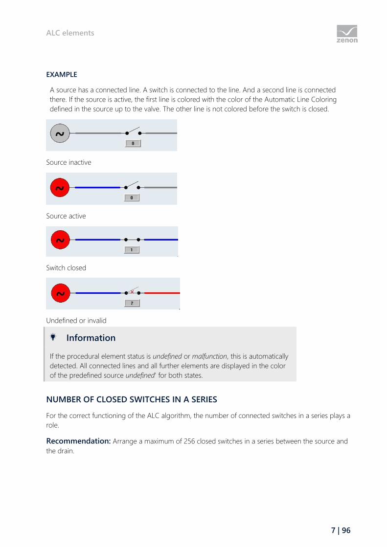
EXAMPLE
A source has a connected line. A switch is connected to the line. And a second line is connected
there. If the source is active, the first line is colored with the color of the Automatic Line Coloring
defined in the source up to the valve. The other line is not colored before the switch is closed.
Source inactive
Source active
Switch closed
Undefined or invalid
Information
If the procedural element status is undefined or malfunction, this is automatically
detected. All connected lines and all further elements are displayed in the color
of the predefined source undefined' for both states.
NUMBER OF CLOSED SWITCHES IN A SERIES
For the correct functioning of the ALC algorithm, the number of connected switches in a series plays a
role.
Recommendation: Arrange a maximum of 256 closed switches in a series between the source and
the drain.
ALC elements
8 | 96
3.1 Procedural elements via Combined element
Procedural elements are created in zenon with a combined Element. Their state determines the
coloring of the connected line.
Attention
When ALC is activated, the combined element has no effect on the drawing of
lines. It only controls the visibility of elements.
This means: Even invisible lines continue to forward their colors.
This also applies to ALC lines whose visibility is determined by a variable. This
does not include lines with Alias. These display the color, but do not forward it.
SETTINGS
The procedural type of the combined element is defined by the value of the Function type property.
The available options are:
Function type Description
No function The element has no function in the ALC.
Note: The "no function" function type is the default value.
Source Passes on its color. If the source is active (value: 1), all connected lines
that have the Color from ALC option set in the Automatic Line
Coloring properties group are allocated the color of the source. The
color is defined in the project properties as the source color. (e.g. tanks
or generators). A source is a single pole with a static source number
assigned to it. The source is switchable over the state of its main
variable. Generally, sources are considered as net-synchronous and
detachable.
For the Interconnect various voltage levels topological interlocking (on
page 34), the nominal voltage of the source is taken into account.
You can find details on the source in the configuration of the sources
(on page 29) chapter.
Generator A generator generally behaves like a source, but it is considered as an
independent and not net-synchronous.
For the Interconnect grids topological interlocking (on page 34), the
number of the source that is linked to a generator is taken into account.
Switch With this lines can be split. If the switch is closed/active (value: 1), then
the connection between the two lines is closed and the line is colored in
the Runtime up to the next switch with the defined source color. In this

ALC elements
9 | 96
Function type Description
case a switch forwards the source color of the input line to the output
line.
If the status of the switch is invalid (value: 3) or undefined (value: 2) or
the status of the main variable is INVALID, the line is colored in the
undefined color from the ALC configuration. The parameters of the
colors are configured in the ALC configuration property in the
Automatic Line Coloring project properties group. A switch thus
delivers source number 0 (undefined) to its output (connection 2)
instead of the incoming source number.
Example: see Switch example - colors from ALC (on page 14) section.
Note: If the Switch input/output property is active, the input and
output of this element are reversed for the ALC.
Disconnector A disconnector generally behaves like a switch. However, a disconnector
in the topological model must not be switched when live - topological
interlocking "Disconnector under load" in the command processing.
As with the switch, the main variable determines the status: On, off,
intermediate position, malfunction.
Note: If the Switch input/output property is active, the input and
output of this element are reversed for the ALC.
Transformer A transformer is a drain and a source at the same time. SO with a
transformer the input color (input source) can be transformed to a new
output color (transformer source color).
The output line is only displayed as active once the transformer has an
active input line. However the output line does not get the color of the
input line as with a switch, but instead the color of the transformer's
own source. So a source has to be defined for each transformer. A
transformer cannot be switched active or inactive, it always is active,
regardless of the value of the linked variable.
Note: If the Switch input/output property is active, the input and
output of this element are reversed for the ALC.
Reverse-feed-compatible transformer:
To have a transformer capable of reverse feed, you must select, for
Source for reverse feed, a different source than UNDEFINED [0]. This
means that the transformer behaves the same for both directions - from
the input to the output (forward) and also from the output to the input
(backward). The only difference is that the source number of the

ALC elements
10 | 96
Function type Description
Source for reverse feed property and not the Source property is used
for relaying the information (e.g. colors) in the topological model.
Note: Faulty network statuses or missing configurations, such as a feed
from the input and output at the same time or a short circuit from input
and output are not specially colored. This means that the transformer
capable of taking a reverse feed behaves like two transformers switched
to run antiparallel that are not capable of taking a reverse feed.
Capacitor The capacitor can only be connected as a load on one side. For the
Load flow calculation, the capacitor serves as compensation for the
reactive power.
Valve A slider (a valve) acts in a similar manner to a switch, but it is used for
water and gas lines.
Value of the main variable:
Switch OFF: Value 0 -> Slider closed-> No forwarding
Slider ON: Value 1 -> Slider open completely-> Water flow
Slider value 2 (intermediate) -> Slider partially open-> Water flow
Slider value 3 (error) -> Slider malfunction
Note: If the Switch input/output property is active, the input and
output of this element are reversed for the ALC.
Check valve The check valve only forwards information in one direction.
Value of the main variable:
Value 0:
The forwarding is not active (= the valve is closed)
Value 1 or 2:
Forwarding is only possible in one direction. In doing so, the
color of the source is only forwarded from the input to the
output. Forwarding in the opposite direction is not envisaged.
This also concerns the forwarding of ALC information for the
color of the earth.
Value 3:
Forwarding is undefined. This then occurs, for example if the
check valve is faulty. In this case the status is only forwarded at
the output.
Note: If the Switch input/output property is active, the input and
ALC elements
11 | 96
Function type Description
output of this element are reversed for the ALC.
The check valve is also taken into account by the topological
interlocking (on page 34).
Drain This defines the end of the line. The drain does not influence the
coloring; it is only used so that the model can be displayed in full. If an
external program (e.g. VBA) should access the model, then the drain
probably is needed for further calculations, and so has to be inserted.
In Energy projects, the drain is used for representing consumers. These
are used to calculate the ALC - topological interlockings (in the
command processing) 'Device would not be supplied'.
Terminator For bus bar ends. Blocks the error message "Line only connected on one
side" when being compiled in the Editor.
Link A link serves to continue a line at another place. If a link is "supplied" by
a line, all other links with the same link name also are supplied by this
line. Here it does not matter, whether the links are in the same screen
or on different screens in the project. Topological networks can thus be
designed throughout screens. More than two links with the same link
name in the project are also permitted.
Links are configured with the Link name property.
Links can be supplied by several lines at the same time or can
themselves supply several lines. In principle there is no difference
between inputs and outputs. The ALC colors of the sources are
forwarded to all connected lines.
A link cannot be switched active or inactive in the event of a value
change: it is always active. For this reason, it is not absolutely necessary
to link the combined element to a variable.
Caution: Two link elements cannot be connected directly to one line.
In between, there has to be at least one other procedural element
(switch/disconnector or transformer).
The source number given - for the source and transformer function types - is forwarded via closed
switches (disconnnectors, sliders etc.) up to the devices (drains). The colors of all connected lines and
process-related elements are calculated dynamic from the higher-level sum of the supplying source
numbers.

ALC elements
12 | 96
SOURCE AND LINK NAME
Parameter Description
Source Here a source is assigned to an element. In this drop-down list all sources
defined in the ALC configuration (in the project properties) are available.
All source names are listed.
This property is only active if the function type 'source', 'transformer' or
'generator' has been selected.
You can find details on the source in the configuration of the sources (on
page 29) chapter.
Attention: Use the pre-defined system sources for this (ID 0..9).
Configure separate sources for this linking:
For the configuration of your own sources, click the ... button in the
ALC configuration property in the Automatic Line Coloring
project properties group.
The system sources UNDEFINED [0], GROUND FAULT [1], SHORT
FAULT [2] and GROUNDED [3] are only envisaged for the
configuration of the grounding.
The pre-defined system sources SYSSOURCE4 [4] to SYSSOURCE9
[9] serve as placeholders.
Link name The link name can be configured here for the link function type. All
identical link names in a project correlate with each other.
You can find further information about this in the Link function type.
This property is only active, if the function type link has been selected.
VARIABLES OF PROCESS-RELATED ELEMENTS
In order for a switch, disconnector or slider etc. to be given the status (open, closed, invalid), a BOOL
data type or integer variable must be linked in the respective combined element as the main variable.
Example:
IEC870 driver: Variables with Typ ID T01..T37
IEC850 driver: Variables */Pos/stVal[ST]
DNP3 driver: Input Variables
Pre-requisite: the DPI/DPC mapping has not been deactivated in the driver.

ALC elements
13 | 96
Information
For the position of a switch, only the first two bits of the main variable are taken
into account.
The first bit is the actual switching; 0 is OFF and 1 is ON.
The second bit is the error bit. There is no error if it is 0.
The status of a source ("present" (ON) / "not present" (OFF)) is also evaluated using the linked main
variable. For this evaluation, a BOOL data type variable of the internal driver is recommended. Then
(as is usual in practice) the source can be linked to the rest of the topology via a switch or
disconnector. As a result, it is possible to forward the color of the source - depending on the position
of the switch.
Note: For the main variable of a source that is connected to the network via a switch/disconnector
(ground, for example), create a variable for the internal driver. For this variable, configure the
Calculation properties with the value network and Initial value with value 1 ("always present"). You
can find this properties in the Internal Variable variable properties group. Alternatively, you can also
link a source to the process variable directly (the source and its switch in one). As a result, you can
deactivate or avoid the topological interlocking when switching the source.
STATUSES
The following applies for statuses:
A switch and a source are switched on (closed) if the value of the linked variable is 1.
A switch is invalid if the value of the linked variable is >1 or has an INVALID status bit.
An invalid switch provides the source number 0 (undefined) at its exit (connection 2) instead
of the source number entering. In the direction from input to output, the switch behaves as if
it were open.
Note: if the main variable has the status INVALID, the whole subsequent network is INVALID,
because the status of the network is not known. The status INVALID is forwarded using
subsequent closed switches.
Attention
If, in the statuses of the combined element, the color and the fill color from the
ALC property is activated, it is not just the lines but also the procedural elements
that are colored in the Runtime.
ALC elements
14 | 96
3.1.1 Switch example - colors from ALC
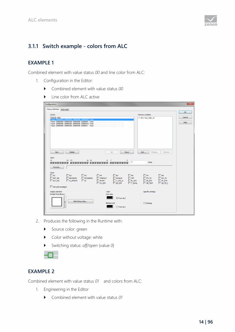
EXAMPLE 1
Combined element with value status 00 and line color from ALC:
1. Configuration in the Editor:
Combined element with value status 00
Line color from ALC active
2. Produces the following in the Runtime with:
Source color: green
Color without voltage: white
Switching status: off/open (value 0)
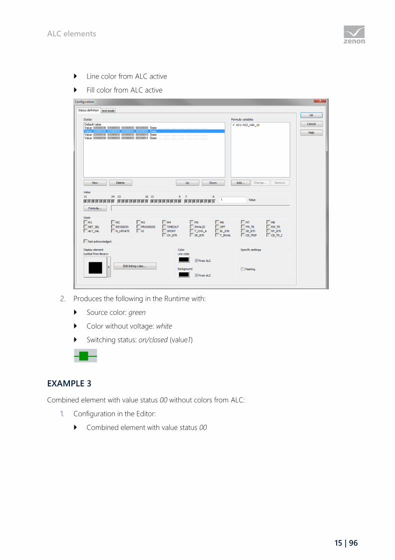
EXAMPLE 2
Combined element with value status 01 and colors from ALC:
1. Engineering in the Editor
Combined element with value status 01
ALC elements
15 | 96
Line color from ALC active
Fill color from ALC active
2. Produces the following in the Runtime with:
Source color: green
Color without voltage: white
Switching status: on/closed (value1)
EXAMPLE 3
Combined element with value status 00 without colors from ALC:
1. Configuration in the Editor:
Combined element with value status 00

ALC elements
16 | 96
Line color from ALC not active
2. Produces the following in the Runtime with:
Source color: green
Color not energized and construction color of the line: white
Defined line and fill color of the combined element: black
Switching status: off/open (value 0)
EXAMPLE 4
Combined element with value status 01 without colors from ALC:
1. Engineering in the Editor
Combined element with value status 01
Line color from ALC inactive

ALC elements
17 | 96
Fill color from ALC inactive
2. Produces the following in the Runtime with:
Source color = green
Color not energized and construction color of the line: white
Defined line and fill color of the combined element: black
Switching status: on/closed (value1)
3.1.2 Connection points of procedural elements
When configuring, a line is connected to a procedural element (combined element) by overlapping
drawings in the screen at connection points of the combined element. Only one line can be
connected to the same connection point at the same time. All lines that start within the area defined,
are connected (Topology from the graphic).
ALC elements
18 | 96
Attention
Use ALC elements only in un-rotated state because:
The calculation for the topological model for the ALC in the Editor is based on
the position of the elements in un-rotated state and without considering any
dynamics.
CONNECTION POINTS AND CONNECTION AREAS
The connection area for a connection point is in the middle of each side of the combined
element. Each combined element thus has four connection points.
The size of a connection area corresponds to 2/3 of the height and width of a combined
element, but no more than 20 pixels.
Each connection area is centered in the middle of the respective element corner and
stretches symmetrically inwards and outwards, to a maximum of 10 respective pixels.
Attention
If the combined element is less than 30 pixels, connection areas within an
element overlap. Lines that could touch can cause errors (compilation, coloring).
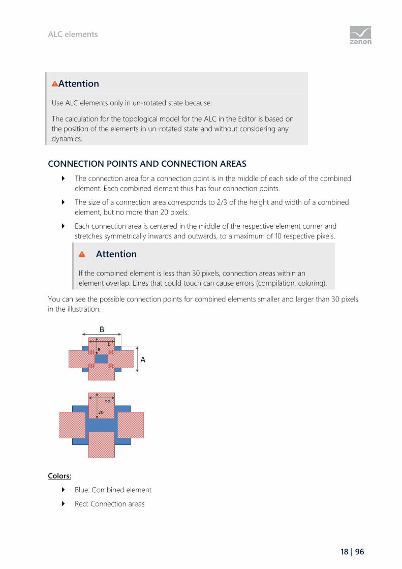
You can see the possible connection points for combined elements smaller and larger than 30 pixels
in the illustration.
Colors:
Blue: Combined element
Red: Connection areas
ALC elements
19 | 96
Dimensions:
A: height of the Combined element
B: width of the Combined element
a: Width of the connection area: 2/3 of A, but a maximum of 20 pixels.
b: Length of the connection area: 2/3 of B, but a maximum of 20 pixels.
RULES
If a line is outside the connection area, no connection is detected and there is thus no
coloring of the line. So there will also be no coloring for further lines.
With sources, drains and Links, all described connection points can in principle be used.
Attention: With sources and drains, only one connection point can be used at the same
time. If different connection points are used at the same time, undefined states can occur.
Elements of the type Link can also use several connection points at the same time. The
incoming color information is passed on to all lines.
With switches/disconnectors/sliders and transformers, the connection 1 (supply) is on the left
or on the top and connection 2 (output) is on the right or on the bottom. This sequence can
be changed with the Switch input/output property.
Attention: At switches and transformers it has to be cared, that only one input connection
and one output connection is used. The simultaneous use of several input or output
connection points results in inconsistencies and is therefore not reliable.
For all procedural elements the following is true: Only one line can be connected to a
connection point. Junctions cannot be realized directly on an element but must be drawn
with lines.
3.1.3 Switch input/output
If a transformer, a disconnector or a switch is configured, the input and output can be swapped. To
do this:
1. Select either transformer, disconnector or switch as a Function type
2. Activate the checkboxSwitch input/output
The input is then set at the bottom right and the output at the top left.
OVERVIEW
Device configuration Input Output
normal left right
normal top bottom

ALC elements
20 | 96
Device configuration Input Output
swapped right left
swapped bottom top
3.1.4 Measuring points
Variables are linked for the visualization of ALC sources that currently supply the process-technical
element or start from this element.
These variables are supplied with the current values from the ALC module. Names of the sources can
be visualized by the ALC module by displaying these variables.
These properties are summarized in the Automatic Line Coloring properties group combined
element and summarized in the Condition area.
Configurable properties:
Input active sources
(STRING data type)
Output active sources
(STRING data type)
Highest priority source input
(numeric data type)
Highest priority source output
(numeric data type)
DISPLAY IN RUNTIME
The linked variables are displayed with the following values in zenon Runtime:
Number (on page 29) of the active sources (STRING data type):
Active source number(s): The numbers of all active sources are summarized in a STRING
variable.
This is applicable for both input and output.
Several source numbers are separated by a semicolon (;). Sorting is carried out
according to the priority of the source.
Note: With multiple sorting, the source is represented with several entries at the input.
<Empty>: not supplied
Number of the highest priority source (numerical variable):

ALC elements
21 | 96
0 or greater: Number of the highest priority source. This is applicable for both input and
output.
-1: not supplied
3.2 Lines
Lines are represented by the vector elements Line, Polylines and Pipe.
If the Color from ALC property is activated for a line, the coloring is defined by the ALC
configuration. Lines are automatically colored by the system depending on the status of the
procedural elements and the ALC settings. The color is usually defined by the highest priority source
number of the medium flowing through the line. If the status is empty/not supplied, the element is
not colored by Automatic Line Coloring. In this case, the configuration of the Line color property (in
the Line properties group or Line color in the Line color dynamic properties group) is used for
visualization in the Runtime.
Attention
Even invisible lines that have an activated Color from ALC property continue to
forward the colors to the linked ALC elements. This forwarding occurs regardless
of whether they are visible or invisible in the Runtime.
Exception: Lines with Alias display the color, but do not forward it.
Note: A line can be displayed invisibly due to:
Configurations of the properties of Visibility:
The properties are located in the Visibility/flashing properties group
states of the Combined element that do not currently apply
The ALC color will continue to be forwarded nonetheless. The value of the linked variable does not
play a role. It only affects visibility, not the forwarding.
You define the display type of the line by means of drop-down lists:
Priority for display
display multiple supplies
display secured supply
The following options are available in the properties of the lines:
Parameter Description
Color from ALC Activates the automatic line coloring for this vector element.
That means: If the source for the line is active and all
switches/valves leading from the source to the line are closed,
the line is colored accordingly. If the line is fed by a single

ALC elements
22 | 96
Parameter Description
source, the defined source color is used for coloring the line.
The line width is not changed.
Note: If Alias is activated, this alters the behavior. The line
then displays the color of a different element and does not
forward it.
Priority for display Defines if multiple supply, secured supply or both are displayed.
Default: Multiple supply
Secured supply The element is displayed according to the rules of the secured
supply.
A line is then considered to have a secure supply if it is
supplied by at least two different switches or transformers with
a non-system source. System sources do not contribute to
secured supply, but do not exclude it.
Multiple supply The element is displayed according to the rules of the multiple
supply.
A line is considered to have multiple supplies if it is supplied by
at least two different sources. In doing do, it does not matter if
they are system sources or user sources and from which side
the line is supplied by the sources.
No priority The coloring rules for multiple supply and for secured supply
are applied at the same time if both criteria are met.
That means: The line is displayed twice as wide and in the form
of a two-colored, dashed line if the following have been
configured for a line:
has multiple supplies and a secured supply
the priority is set to No priority
The display for multiple supply is set to two sources with
highest priority,
the display for secured supply is set to double width
display multiple supplies Multiple supply means that a line is supplied by multiple
sources at the same time. Here you can define how lines with
multiple supply are displayed.
Default:highest priority source
highest priority source The line gets the color of the source with the highest priority.
Note: Priorities correspond to the sequence chosen in the

ALC elements
23 | 96
Parameter Description
ALC configuration.
two highest priority sources Applies for lines fed by two or more different sources. The two
sources with the highest priorities define the coloring. The line
is displayed with these two colors (dashed). The dash length
can be changed using the Dashing length supplied multiple
times property.
System sources apply for multiple supplies just as with genuine
sources and color lines in two colors it they are configured
accordingly.
Alternative color The color defined in the Alternative color property is used.
Dashing length supplied
multiple times
Defines the dash length (in pixels) of lines, polylines or tubes
for the dashed ALC coloring for two sources with the highest
priority for display multiple supplies.
Possible values:
Minimum: 0 (automatic dash length)
Maximum: 32767
Default: 0
Alternative color Alternative color for the ALC coloring of lines, polylines or
tubes with multiple supplies.
display secured supply Secured supply means that a line gets multiple supplies from
one source (parallel). Here you can define how Secured supply
is displayed.
A line is always displayed as having a secure supply if it is
supplied by at least two switches with a genuine source (not
system source).
Default: normal
double width Relevant for lines fed in parallel by the same source. If this is
the case, the line is displayed with double the configured
width.
Example: A line of line width 5 is displayed with a width of 10 if
it has a secure supply.
If this line is fed by two or more different sources
(multi-supply), the line width does not change!
The color is always defined by the source with the highest
ALC elements
24 | 96
Parameter Description
priority!
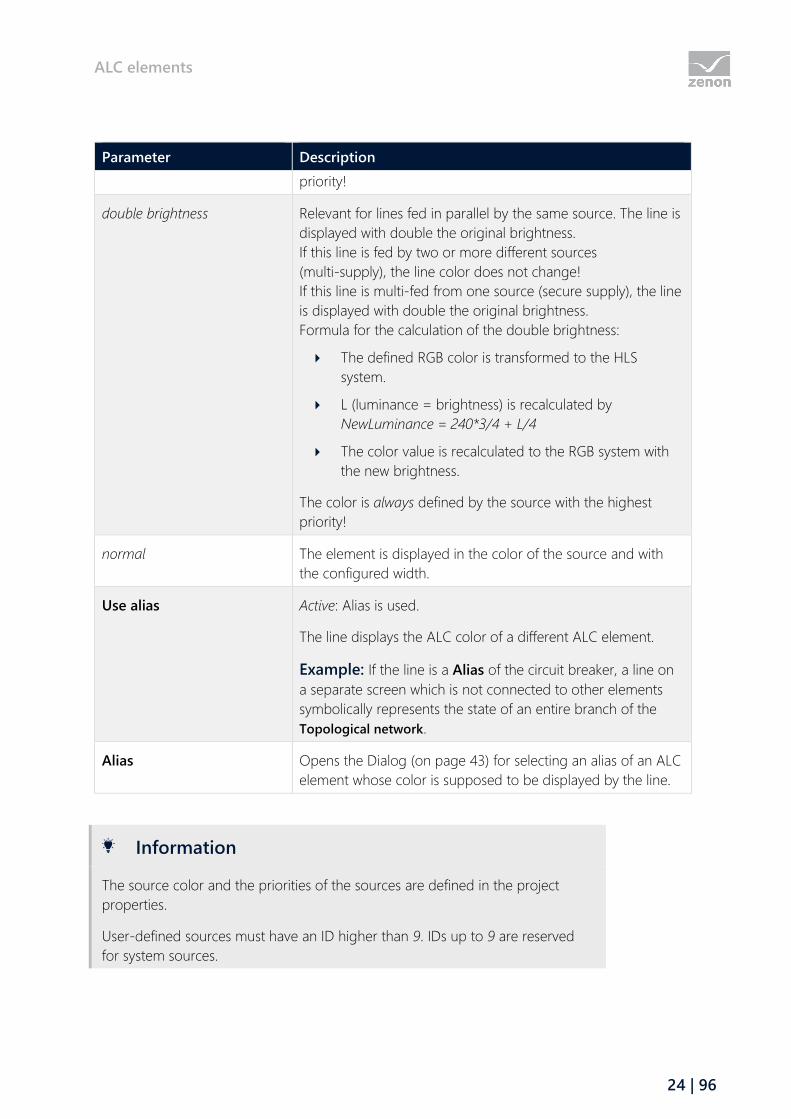
double brightness Relevant for lines fed in parallel by the same source. The line is
displayed with double the original brightness.
If this line is fed by two or more different sources
(multi-supply), the line color does not change!
If this line is multi-fed from one source (secure supply), the line
is displayed with double the original brightness.
Formula for the calculation of the double brightness:
The defined RGB color is transformed to the HLS
system.
L (luminance = brightness) is recalculated by
NewLuminance = 240*3/4 + L/4
The color value is recalculated to the RGB system with
the new brightness.
The color is always defined by the source with the highest
priority!
normal The element is displayed in the color of the source and with
the configured width.
Use alias Active: Alias is used.
The line displays the ALC color of a different ALC element.
Example: If the line is a Alias of the circuit breaker, a line on
a separate screen which is not connected to other elements
symbolically represents the state of an entire branch of the
Topological network.
Alias Opens the Dialog (on page 43) for selecting an alias of an ALC
element whose color is supposed to be displayed by the line.
Information
The source color and the priorities of the sources are defined in the project
properties.
User-defined sources must have an ID higher than 9. IDs up to 9 are reserved
for system sources.
ALC elements
25 | 96
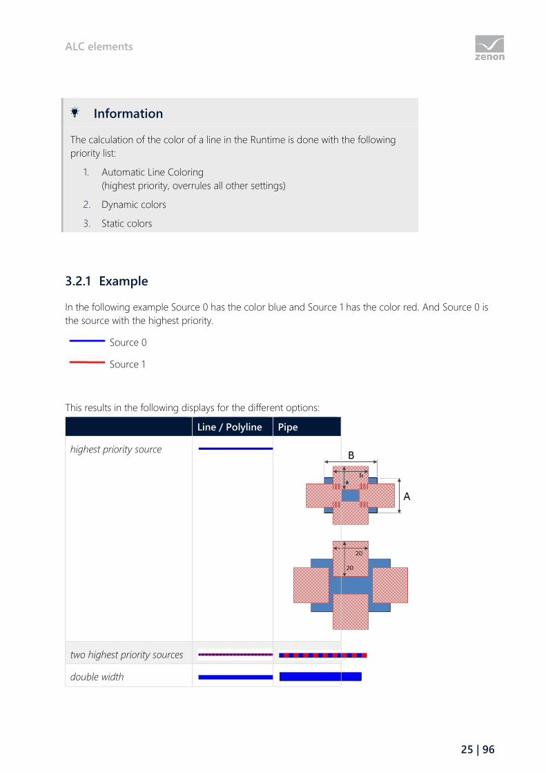
Information
The calculation of the color of a line in the Runtime is done with the following
priority list:
1. Automatic Line Coloring
(highest priority, overrules all other settings)
2. Dynamic colors
3. Static colors
3.2.1 Example
In the following example Source 0 has the color blue and Source 1 has the color red. And Source 0 is
the source with the highest priority.
Source 0
Source 1
This results in the following displays for the different options:
Line / Polyline Pipe
highest priority source
two highest priority sources
double width
ALC elements
26 | 96
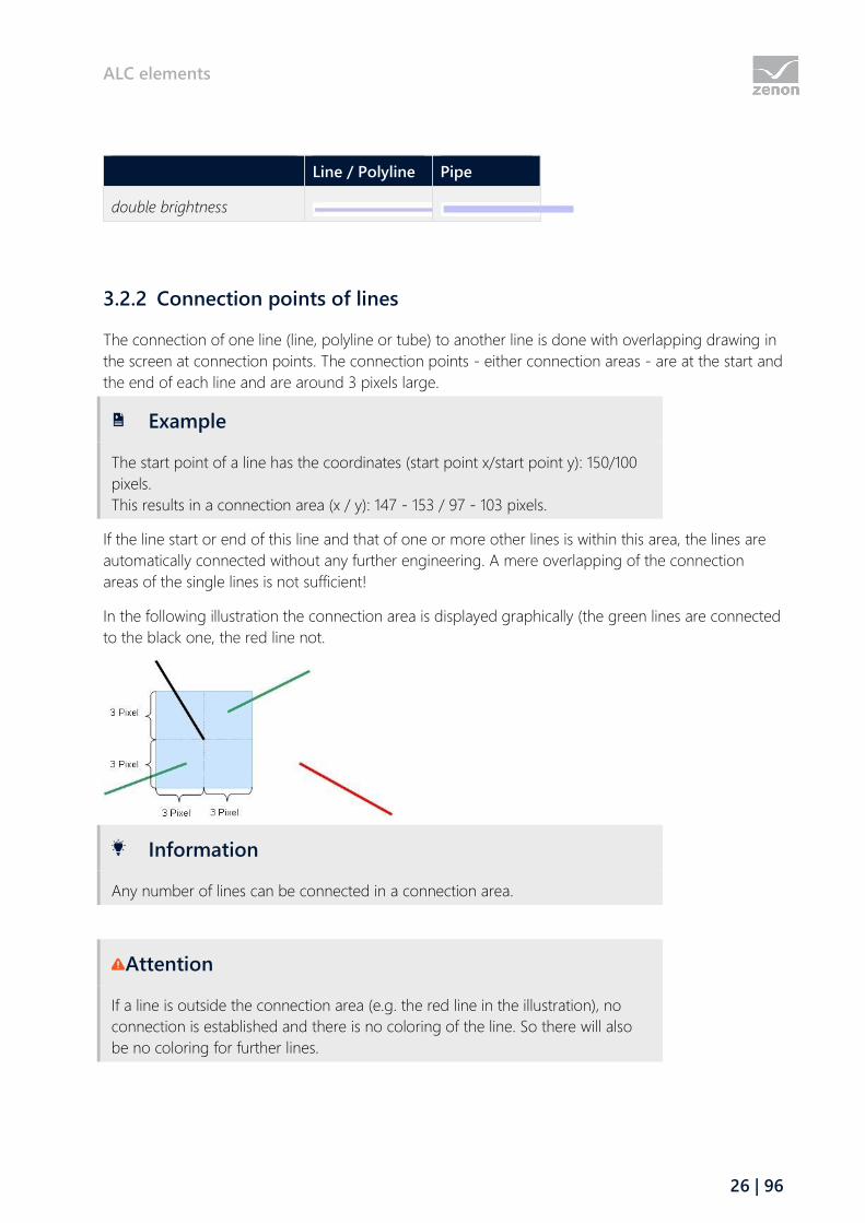
Line / Polyline Pipe
double brightness
3.2.2 Connection points of lines
The connection of one line (line, polyline or tube) to another line is done with overlapping drawing in
the screen at connection points. The connection points - either connection areas - are at the start and
the end of each line and are around 3 pixels large.
Example
The start point of a line has the coordinates (start point x/start point y): 150/100
pixels.
This results in a connection area (x / y): 147 - 153 / 97 - 103 pixels.
If the line start or end of this line and that of one or more other lines is within this area, the lines are
automatically connected without any further engineering. A mere overlapping of the connection
areas of the single lines is not sufficient!
In the following illustration the connection area is displayed graphically (the green lines are connected
to the black one, the red line not.
Information
Any number of lines can be connected in a connection area.
Attention
If a line is outside the connection area (e.g. the red line in the illustration), no
connection is established and there is no coloring of the line. So there will also
be no coloring for further lines.

ALC elements
27 | 96
Line crossings can easily be realized, if the ends of the lines are not in the connection area.
Attention
Use ALC elements only in un-rotated state because:
The calculation for the topological model for the ALC in the Editor is based on
the position of the elements in un-rotated state and without considering any
dynamics.
3.3 Checking the project
Engineer the desired procedural elements and lines in one or more screens and save these screens.
Then you can check via Create all Runtime files or Create changed Runtime files whether there are any
errors or conflicts in the screens. If error or conflicts should exist, corresponding error messages or
warnings are displayed in the output window.
Information
Double click the corresponding line in the output window. The screen with the
erroneous screen element will be opened automatically. If the erroneous screen
element is part of a symbol, the corresponding symbol is automatically selected.
The following error message can be displayed.
ALC: Screen '%s' - Two Link elements with different Link number or name are connected to
line '%s' . (double clicking opens the screen and selects the line.)
ALC: Screen '%s' - More than two connection points are used at element '%s'. For each
element only one input and one output may be used. (double clicking opens the screen and
selects the element)
The following warnings can be displayed.
ALC: Screen '%s' - Alias line '%s' is connected to a no-alias line. (double clicking opens the
screen and selects the line.)
ALC: Screen '%s' - Alias element '%s' is connected to a no-alias line. (double clicking opens
the screen and selects the element)

Configuration
28 | 96
ALC: Screen '%s' - No-alias element '%s' is connected to an alias line. (double clicking opens
the screen and selects the element)
ALC: Screen '%s' - Line '%s' is only connected on one side. (double clicking opens the screen
and selects the line.)
ALC: Screen '%s' - Element '%s' is not connected. (double clicking opens the screen and
selects the element)
ALC: Screen '%s' - Element '%s' is only connected on one side. (double clicking opens the
screen and selects the element)
In the error messages or warnings the corresponding elements are identified using the element
reference. This reference also serves as the link key for ALC aliases.
4 Configuration
To configure ALC:
1. In project properties, select ALC configuration the property in the Automatic Line
Coloring group
2. Click on the ... button.
3. The dialog for configuration is opened
4. Configure the desired properties for:
Sources (on page 29)
Create a new source.
To do this, click on the New button. This creates a new entry with the name Source [serial
number] at the end of the list of the sources.
Note: In doing so, note that the system sources (ID 0..9) have a pre-defined meaning or
are reserved for future versions.
Then configure the colors of the new source by selecting the color value with a mouse
click and clicking on the ... button. This opens the drop-down menu to select the colors.
Note also the principles for coloring for UNDEFINED (on page 33).
Interlockings (on page 34)
Configure which topological interlockings the Command Processing module should take
into account.
Note: this tab is only available with a valid license for the optional ALC - Topology
Package module.
Screen marker (on page 40)

Configuration
29 | 96
Configure the color table for the screen marker for impedance-based fault locating.
Note: this tab is only available with a valid license for the optional ALC - Topology
Package module.
4.1 Configuration of the sources
The sources, e.g. their names and colors (sequence and priority), are configured project-specifically
within the project properties under ALC configuration. Sources with ID between 0 and 9 are
reserved for system sources. The configuration of those that already have a function (such as
GROUNDED - the color of the "earth" source) may not be changed. Those that do not yet have any
functionality in the current zenon version remain reserved for future versions.
Configuration
30 | 96
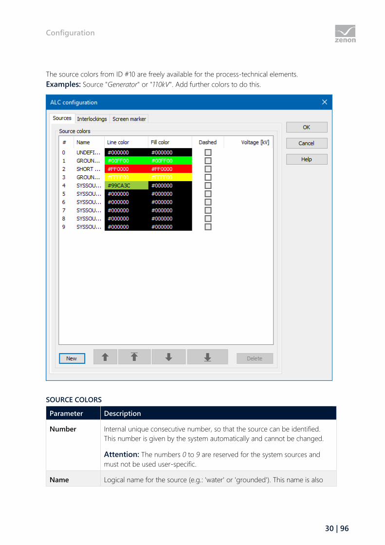
The source colors from ID #10 are freely available for the process-technical elements.
Examples: Source "Generator" or "110kV". Add further colors to do this.
SOURCE COLORS
Parameter Description
Number Internal unique consecutive number, so that the source can be identified.
This number is given by the system automatically and cannot be changed.
Attention: The numbers 0 to 9 are reserved for the system sources and
must not be used user-specific.
Name Logical name for the source (e.g.: 'water' or 'grounded'). This name is also
Configuration
31 | 96
Parameter Description
used when selecting the source number for Combined elements. You can
change the name by clicking it with the left mouse button. With this edit
mode is switched on. The changes are accepted with the Enter key or by
selecting another source.
Note: The labels are not language switchable.
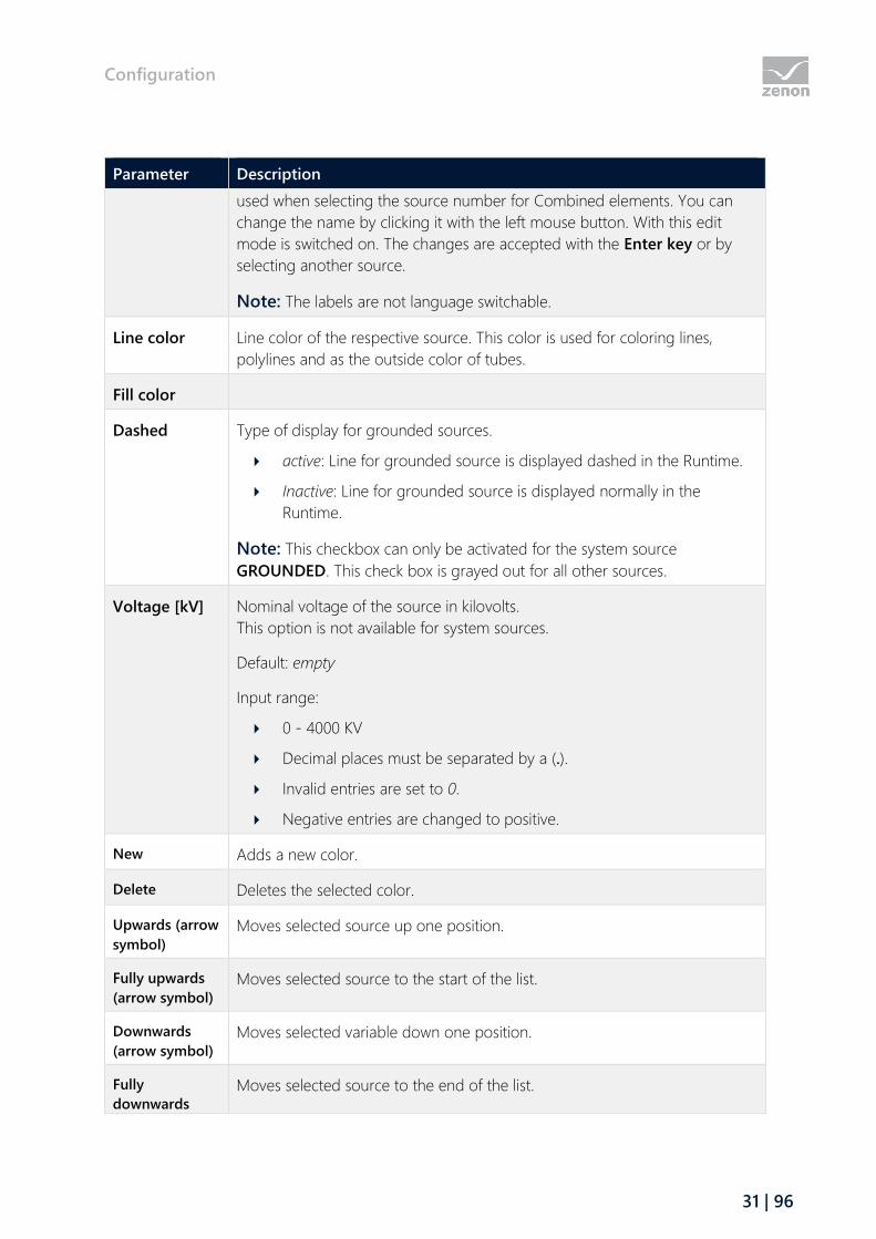
Line color Line color of the respective source. This color is used for coloring lines,
polylines and as the outside color of tubes.
Fill color
Dashed Type of display for grounded sources.
active: Line for grounded source is displayed dashed in the Runtime.
Inactive: Line for grounded source is displayed normally in the
Runtime.
Note: This checkbox can only be activated for the system source
GROUNDED. This check box is grayed out for all other sources.
Voltage [kV] Nominal voltage of the source in kilovolts.
This option is not available for system sources.
Default: empty
Input range:
0 - 4000 KV
Decimal places must be separated by a (.).
Invalid entries are set to 0.
Negative entries are changed to positive.
New Adds a new color.
Delete Deletes the selected color.
Upwards (arrow
symbol) Moves selected source up one position.
Fully upwards
(arrow symbol) Moves selected source to the start of the list.
Downwards
(arrow symbol) Moves selected variable down one position.
Fully
downwards
Moves selected source to the end of the list.
Configuration
32 | 96
Parameter Description
(arrow symbol)
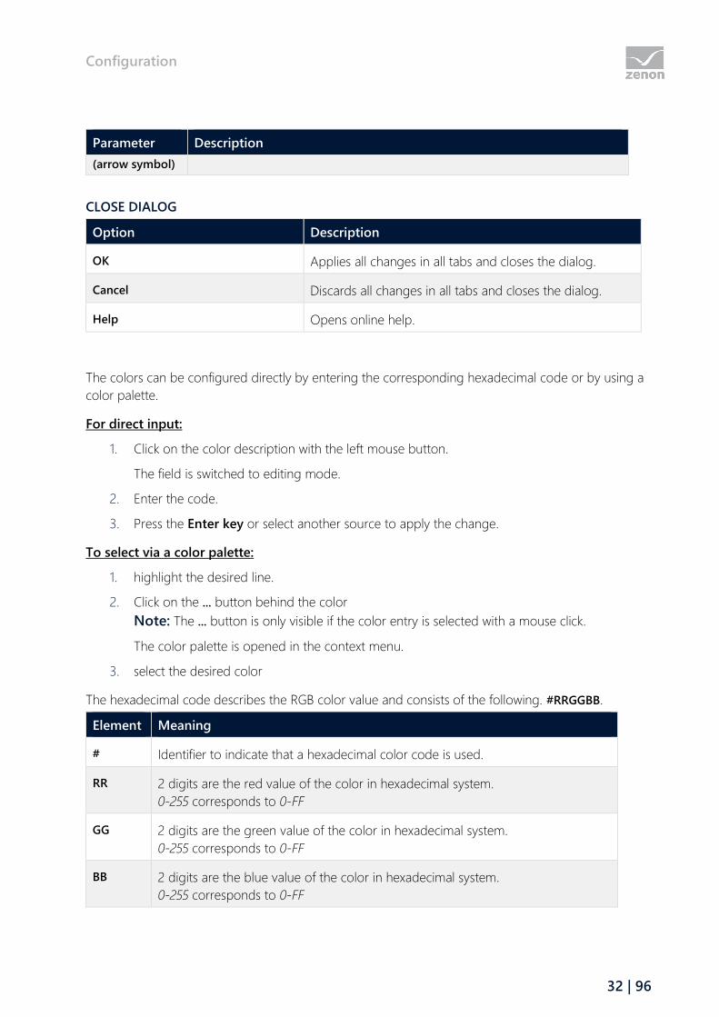
CLOSE DIALOG
Option Description
OK Applies all changes in all tabs and closes the dialog.
Cancel Discards all changes in all tabs and closes the dialog.
Help Opens online help.
The colors can be configured directly by entering the corresponding hexadecimal code or by using a
color palette.
For direct input:
1. Click on the color description with the left mouse button.
The field is switched to editing mode.
2. Enter the code.
3. Press the Enter key or select another source to apply the change.
To select via a color palette:
1. highlight the desired line.
2. Click on the ... button behind the color
Note: The ... button is only visible if the color entry is selected with a mouse click.
The color palette is opened in the context menu.
3. select the desired color
The hexadecimal code describes the RGB color value and consists of the following. #RRGGBB.
Element Meaning
# Identifier to indicate that a hexadecimal color code is used.
RR 2 digits are the red value of the color in hexadecimal system.
0-255 corresponds to 0-FF
GG 2 digits are the green value of the color in hexadecimal system.
0-255 corresponds to 0-FF
BB 2 digits are the blue value of the color in hexadecimal system.
0-255 corresponds to 0-FF

Configuration
33 | 96
Information
The sequence in this list represents the priority of the sources, with the first
element having the highest priority.
To change the priorities of the single sources, they can be moved upwards or
downwards using the arrow buttons
Attention
Limitations when deleting the sources and resetting fault colorings:
Sources with ID between 0 and 9 are reserved for system sources. You can:
not be deleted:
not be reset as an erroneous color
Deleting sources
In order for sources to be able to be deleted, they must have an ID from 10.
Only the source with the highest ID can be deleted.
Resetting erroneous colorings
In order for erroneous colorings to be able to be reset once the cause has been
rectified, no system source colors can be used. A color for IDs from 10 must be
selected.
4.1.1 Coloring mode for UNDEFINED
Coloring in the network can be implemented in two modes with the UNDEFINED status:
Standard
Input takes priority
This setting is made using the Automatic Line Coloring/Mode for coloring project property.
STANDARD
The internal calcualtion of the topology (= graph search) starts with a source and goes through the
whole network, so that each closed switch (switch variable has the value 1) per direction is only gone
Configuration
34 | 96
through once, so no cycles occur. In doing so, each node visited (=line segment) is colored with the
source color. The directly-related lines are marked as a node.
If the search finds a switch that has a switch variable with one of the following states, the UNDEFINED
color is used for coloring from this point onwards:
INVALID [value: any],
is invalid [value: 3]
is in intermediate position [value: 2])
The graph search is now continued in the same form. Each switch is gone through just once per
direction with the UNDEFINED color. Therefore each switch can be gone through a maximum of four
times per source:
1. with source number in forwards direction,
2. with source number in backwards direction,
3. with UNDEFINED in forwards direction,
4. with UNDEFINED in backwards direction,
INPUT TAKES PRIORITY
With the Prior supply setting, only lines that have a supply from at least one source but not clearly
from any one source are colored as UNDEFINED. If a line is supplied with at least one source, it can
no longer receive an UNDEFINED color from another source.
This search is a two-stage search:
In the first stage, as with Standard, the source color is distributed in the network from each
switched source, as long as the next switch is closed. The search is ended if the switch is open
or invalid/undefined.
In the second stage, the search is started at each invalid/undefined switch that receives a
supply from one side and the UNDEFINED color is distributed to the unsupplied side. This
search also considers the switches that are invalid/undefined as closed and thus distributes
the UNDEFINED color in the network until it meets a clearly open switch. In addition, a search
is ended if a line element is reached that is already supplied.
4.2 Configuration of topological interlockings
The Command Processing module can automatically calculate the interlockings in Runtime. These
interlockings are based on the dynamic status of an electricity grid. The topology of the grid is
configured via ALC. If the Command Processing detects that the execution of a command
corresponds to the interlocking condition, the execution of the command is prevented.
Configuration
35 | 96
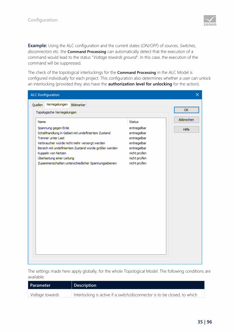
Example: Using the ALC configuration and the current states (ON/OFF) of sources, Switches,
disconnectors etc. the Command Processing can automatically detect that the execution of a
command would lead to the status "Voltage towards ground". In this case, the execution of the
command will be suppressed.
The check of the topological interlockings for the Command Processing in the ALC Model is
configured individually for each project. This configuration also determines whether a user can unlock
an interlocking (provided they also have the authorization level for unlocking for the action).
The settings made here apply globally, for the whole Topological Model. The following conditions are
available:
Parameter Description
Voltage towards Interlocking is active if a switch/disconnector is to be closed, to which

Configuration
36 | 96
Parameter Description
ground grounded potential is connected to and one or more connections in
the ALC model are live or undefined.
This ensures that the voltage towards the ground in a line is also
detected by an intermediate transformer.
Default status: unlockable
Examples:
After switching the element, one side is grounded and the other
is live.
Switching operation
in area with
undefined status
Interlocking is active if a switch/disconnector is to be closed and both of
its connectors are undefined or invalid.
Default status: unlockable
Disconnector under
load
Interlocking is active if certain conditions have been met for switching
the disconnector on (= close) or off (= open).
Default status: unlockable
Conditions: see "Disconnector under load - interlocking conditions (on
page 38)" section.
Device would not be
supplied
Interlocking is active if a switch/disconnector is to be opened and a
device that is switched on and supplied with voltage from a source
(drain) then loses supply.
Default status: unlockable
Area with undefined
status would increase
Interlocking is active if a switch/disconnector is to be closed and one
connector has the status undefined or invalid and the other does not.
The interlocking is also reported if the command has been configured
with the switching direction none.
Default status: unlockable
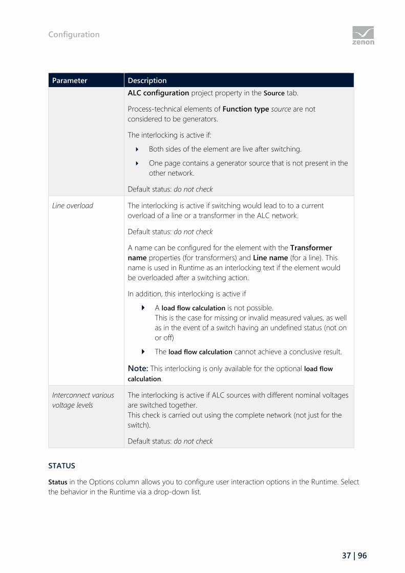
Interconnect grids This interlocking is to prevent unintended connection of two networks
with different generator sources.
Interlocking is active if two ALC network areas in which different
generators are located are switched together. Process-technical
generator elements with different numbers of sources are considered
different generators.
Note: The numbers of the sources are configured in the dialog of the
Configuration
37 | 96
Parameter Description
ALC configuration project property in the Source tab.
Process-technical elements of Function type source are not
considered to be generators.
The interlocking is active if:
Both sides of the element are live after switching.
One page contains a generator source that is not present in the
other network.
Default status: do not check
Line overload The interlocking is active if switching would lead to to a current
overload of a line or a transformer in the ALC network.
Default status: do not check
A name can be configured for the element with the Transformer
name properties (for transformers) and Line name (for a line). This
name is used in Runtime as an interlocking text if the element would
be overloaded after a switching action.
In addition, this interlocking is active if
A load flow calculation is not possible.
This is the case for missing or invalid measured values, as well
as in the event of a switch having an undefined status (not on
or off)
The load flow calculation cannot achieve a conclusive result.
Note: This interlocking is only available for the optional load flow
calculation.
Interconnect various
voltage levels
The interlocking is active if ALC sources with different nominal voltages
are switched together.
This check is carried out using the complete network (not just for the
switch).
Default status: do not check
STATUS
Status in the Options column allows you to configure user interaction options in the Runtime. Select
the behavior in the Runtime via a drop-down list.
Configuration
38 | 96
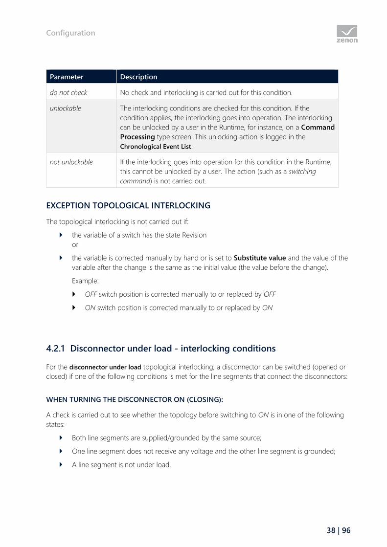
Parameter Description
do not check No check and interlocking is carried out for this condition.
unlockable The interlocking conditions are checked for this condition. If the
condition applies, the interlocking goes into operation. The interlocking
can be unlocked by a user in the Runtime, for instance, on a Command
Processing type screen. This unlocking action is logged in the
Chronological Event List.
not unlockable If the interlocking goes into operation for this condition in the Runtime,
this cannot be unlocked by a user. The action (such as a switching
command) is not carried out.
EXCEPTION TOPOLOGICAL INTERLOCKING
The topological interlocking is not carried out if:
the variable of a switch has the state Revision
or
the variable is corrected manually by hand or is set to Substitute value and the value of the
variable after the change is the same as the initial value (the value before the change).
Example:
OFF switch position is corrected manually to or replaced by OFF
ON switch position is corrected manually to or replaced by ON
4.2.1 Disconnector under load - interlocking conditions
For the disconnector under load topological interlocking, a disconnector can be switched (opened or
closed) if one of the following conditions is met for the line segments that connect the disconnectors:
WHEN TURNING THE DISCONNECTOR ON (CLOSING):
A check is carried out to see whether the topology before switching to ON is in one of the following
states:
Both line segments are supplied/grounded by the same source;
One line segment does not receive any voltage and the other line segment is grounded;
A line segment is not under load.

Configuration
39 | 96
WHEN TURNING THE DISCONNECTOR OFF (OPENING):
A check is carried out to see whether the topology after switching to OFF is in one of the following
states:
Both line segments are supplied by the same source;
One line segment stops receiving voltage, the other line segment is grounded;
A line segment stops being under load.
Information
Meaning of "not under load"
The status not under load means:
Either:
All switches and disconnectors connected to the line segment are open.
Or:
Switches and disconnectors connected to the line segment are closed but
only connect to a further segment that is also not under load.
In addition, all of the following conditions must be met for the status of not
under load:
All sources and consuming devices connected to the line segment are
switched off.
No transformer may be connected to the line segment.
It must not be a line that is only connected to this disconnector (one open
line).

Configuration
40 | 96
4.3 Configuration of the screen marker
Here you configure the color table for the color marker for the impedance-based fault detection and
calculation of load distribution (on page 64). See also: AddMarker.
Parameter Description
Number Unique internal serial number for clear assignment. This number is given by
the system automatically and cannot be changed.
Line color Line color of the screen marker.
Fill color Fill color of the screen marker.
New Adds a new color.
Delete Deletes the selected color.
Note: Only the last color in the list can be deleted. Standard colors cannot
be deleted.
The colors can be configured directly by entering the corresponding hexadecimal code or by using a
color palette.
For direct input:
1. Click on the color description with the left mouse button.
Function: Change ALC source color
41 | 96
The field is switched to editing mode.
2. Enter the code.
3. Press the Enter key or select another source to apply the change.
To select via a color palette:
1. highlight the desired line.
2. Click on the ... button behind the color
Note: The ... button is only visible if the color entry is selected with a mouse click.
The color palette is opened in the context menu.
3. select the desired color
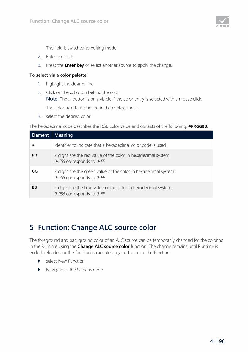
The hexadecimal code describes the RGB color value and consists of the following. #RRGGBB.
Element Meaning
# Identifier to indicate that a hexadecimal color code is used.
RR 2 digits are the red value of the color in hexadecimal system.
0-255 corresponds to 0-FF
GG 2 digits are the green value of the color in hexadecimal system.
0-255 corresponds to 0-FF
BB 2 digits are the blue value of the color in hexadecimal system.
0-255 corresponds to 0-FF
5 Function: Change ALC source color
The foreground and background color of an ALC source can be temporarily changed for the coloring
in the Runtime using the Change ALC source color function. The change remains until Runtime is
ended, reloaded or the function is executed again. To create the function:
select New Function
Navigate to the Screens node
Function: Change ALC source color
42 | 96
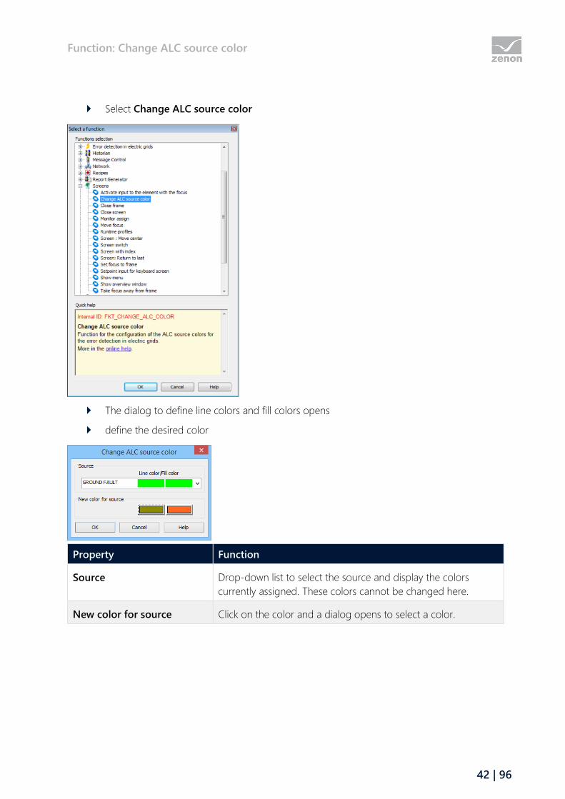
Select Change ALC source color
The dialog to define line colors and fill colors opens
define the desired color
Property Function
Source Drop-down list to select the source and display the colors
currently assigned. These colors cannot be changed here.
New color for source Click on the color and a dialog opens to select a color.
Alias for detail screens
43 | 96
6 Alias for detail screens
To display individual screens, a partial area can be taken from the topological network and displayed
individually by means of an Alias. The screen elements in the detail screen are not included in the
topological model, but do however get their ALC colors from the model. These screen elements
relate to an alias of the screen elements from the overall screen.
Attention
Aliases are only valid within a project.
This means that for symbols that contain elements with links to aliases:
If the symbol is added to the general symbol library or the library in the global
project and edited there, all ALC alias information is lost without notice!
CREATE ALIAS
Aliases can be created for the elements:
Line
Polyline
Pipe
Combined element
Attention
An ALC alias cannot be created if a period (.) is contained in the name of the
selected screen.
Solution: Replace the period in the screen name with a different character, such
as an underscore for example (_).
To create a source element as an alias:
Activate, in the Automatic Line Coloring properties group for the element, the Use alias.
Note: To do this, the ALC module must be licensed and the Color from ALC property must
be activated.
In the Alias property, click on the ... button.
Alias for detail screens
44 | 96
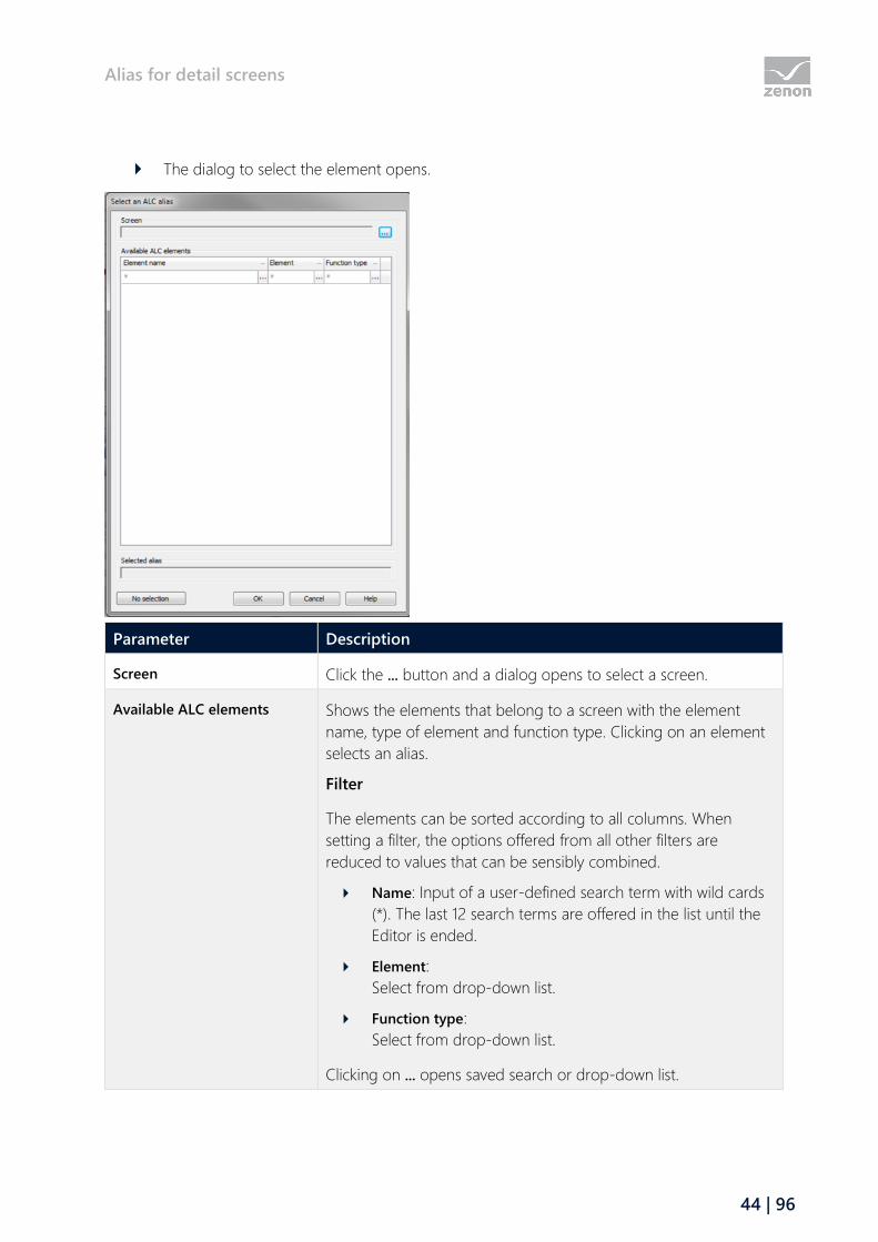
The dialog to select the element opens.
Parameter Description
Screen Click the ... button and a dialog opens to select a screen.
Available ALC elements Shows the elements that belong to a screen with the element
name, type of element and function type. Clicking on an element
selects an alias.
Filter
The elements can be sorted according to all columns. When
setting a filter, the options offered from all other filters are
reduced to values that can be sensibly combined.
Name: Input of a user-defined search term with wild cards
(*). The last 12 search terms are offered in the list until the
Editor is ended.
Element:
Select from drop-down list.
Function type:
Select from drop-down list.
Clicking on ... opens saved search or drop-down list.
Fault locating in electric grids
45 | 96
Parameter Description
If a filter is active, clicking on the X deletes the filter.
Selected alias Shows the selected element in the field of Available ALC elements.
no selection Removes selected element.
OK Saves selection and closes dialog.
Cancel Discards changes and closes dialog.
Help Opens online help.
Information
When selecting an element for a new alias, only elements and screens from the
same project that the alias was defined in can be selected. Elements from
subprojects or parallel projects are not available.
REPLACING ALIAS NAMES
Aliases can be changed when switching screens with Replace link. A detail screen can therefore be
displayed with the data from different equipment parts, for instance lines or partial networks. Alias
names are replaced along the lines of variables and functions. It is also possible to replace in elements
that are used in symbols. For selecting the target the same selection dialog is opened as for the Alias
property.
7 Fault locating in electric grids
Fault location uses special coloring via ALC to mark the parts of a network that have a ground fault or
earth fault. Starting points for fault detection are called ground fault or short circuit recognition device
(such as a detector of a protective device) that are assigned to a circuit breaker. It is assumed that the
ground fault and short circuit reporters are always at the output of the circuit breaker element. For
this reason, when configuring, the corresponding variables (with detection from the protective device)
should be linked to Function type switch elements.
The detections from protective devices are displayed with special coloring with the source colors ID 1
and ID 2. The coloring is only carried out if the detection is applicable for a protective device whilst
the lines are live. At the same time as this, the detections are set to the additional variables for display.
Faults can thus also be shown graphically in a zenon screen. This display can, for example, be carried
out by the configuration of an additional combined element that is only visible if the corresponding
status (= invalid status) is the case.

Fault locating in electric grids
46 | 96
The display must be reset manually (acknowledged) once the protective devices have retracted the
reports.
Information
This function is only available when both the "Energy Edition" and the
"Automatic Line Coloring" modules are licensed.
ERROR DETECTION
Error detection runs locally on each computer in the zenon network. Each client in the network has its
own independent model and can therefore search for ground faults and short circuits in different
parts of the topology.
Error detection in the electrical network is divided into:
Search for ground fault (on page 47)
Search for short-circuit (on page 54)
To configure error detection
You require a license for ALC and zenon Energy Edition
configure the appropriate screens
Configure (on page 8) ALC to the corresponding combined elements with the switch function
configure (on page 21) the lines so that they are colored by ALC
Special functions are available in the Runtime for error detection:
Start search for ground fault (on page 52)
acknowledge (on page 53) ground fault message (on page 53)
Stop search for ground fault (on page 54)

Fault locating in electric grids
47 | 96
Acknowledge short-circuit message (on page 57)
COLORINGS
Errors can be displayed with special coloring of the lines in the ALC if the notifications are received
whilst the lines are live. In the Runtime, the color assigned by ALC changes automatically as soon as
the status of the line changes. The colorings configured can be changed in the Runtime via the
Change ALC source color (on page 41) function.
Messages are processed in the order in which they arrive. In the event of conflicts
The colors for displaying errors take priority
short circuit messages have priority over ground fault messages
7.1 Search for ground fault
The search for a ground fault serves to highlight the network parts that may have a ground fault by
coloring these. The color is taken from the engineering of ALC source colors (on page 28) for the
GROUND FAULT (ID 1) source. At the same time as this, the notifications are set to the additional
variables for graphical display.

Fault locating in electric grids
48 | 96
The network parts that may have a ground fault are derived from the ground fault indication from
ground fault detection devices (ground indicators, protective device that records ground faults). The
following is applicable for ground fault indications:
Each device can have one, two or three ground fault indications.
This ground fault indications are handled either by permanent indication processing or by
wiper indication processing.
For directional ground fault detection devices with direction detection, the direction can be
lagging or leading in relation to triggering.
Leading:
Initially, the indication is determined using the direction (forwards and/or backwards)
and reported, then the indication by means of triggering.
Lagging:
First the triggering, then the direction is determined and reported.
Information
A network component that may have a ground fault is then no longer
considered to have a ground fault if this has been successfully connected.
ENGINEERING
To configure a search for a ground fault:
1. assign the combined element that represents the switching element to the Function type
switch (on page 49)
2. Define the mode of search for ground fault (on page 48), ground fault trigger (on page 51)
and ground fault display (on page 50).
3. Create the functions for start search for ground fault (on page 52), acknowledge ground fault
indication (on page 53) and end search for ground fault (on page 54)
Information
In order to also be able to limit ground faults in mixed networks, only one area
with ground faults is searched per path, starting with a source.
7.1.1 Mode of the search for ground faults
The ground fault search can either:
color the network part potentially subject to a short circuit
or
Fault locating in electric grids
49 | 96
the whole network where the short circuit is located
The coloring mode is defined via the Mode of the search for ground faults property.
To configure the property:
navigate to the Automatic Line Coloring node in properties
select the desired mode in the Mode of the search for ground faults property drop-down
list
Color grid part: colors only the grid parts that are potentially subject to a short circuit
Color entire grid: colors the entire coherent grid, in which a ground fault is located
This setting can be changed in the Runtime via the zenon API object model. In doing so, the ground
fault search is recalculated once again.
7.1.2 Ground fault detection type
The direction and type of message processing for the combined element of type switch are
configured by means of the Type property.
To do this, carry out the following steps:
1. Navigate to the Automatic Line Coloring property group in the combined element
properties
2. Navigate to the area Ground fault recognition
3. Select the desired type with direction and type of indication processing from the drop-down
list in the Type property
Direction:
indicates if the raising edge of trigger indication or if the raising edge of a direction
comes before it
leading:
The current direction status is used for the raising edge of the trigger indication.
lagging:
after a raising edge of the trigger indication, the first raising edge of a direction is waited
on; if this does not occur within 2 seconds, the earth fault device is considered
non-directional
Indication processing:
Specifies how indications are processed.
none:
normal switch; indications are not processed
Permanent indication processing:
Newly received indications are considered as new ground fault trip
Fault locating in electric grids
50 | 96
Wiper message processing:
Indications that are received during a current Search (on page 52) are suppressed
Note: The distinction between permanent indication processing and wiper indication processing is
only how the message is processed, not its type. Wiper indication processing thus does not need to
relate to a wiper bit.
Attention
To suppress intermittent ground faults, ground fault indications that occur in
intervals of less than 2s are ignored.
7.1.3 Ground fault display
The variable linked at Display is an output variable for fault detection and displays the recorded
status of the ground fault identification device. This is necessary because all indications remain saved
internally until until they are acknowledged. The saved indications thus do not necessarily correspond
to the current status of the message variable.
Each time a recording is made, a set value is sent to this variable. In doing so, the values are as
follows:
Value Meaning
0 no ground fault
1 ground fault forwards
2 Ground fault backwards
3 non-directional ground fault
4 Fault status - > both directions have activated
Information
To reduce problems in network operation, the variable linked here should be a
local variable.

Fault locating in electric grids
51 | 96
7.1.4 Earth fault triggering
The variable for the earth fault detection device indication is defined via the Triggering property. It
can contain information on the presence of an ground fault and the direction of the ground fault
from the point of view of the ground fault recognition device. In doing so, a distinction is made
between:
Non-directional ground fault recognition devices
directed ground fault recognition devices with a trip alarm
directed ground fault recognition devices without a trip alarm
To configure the variable for the Triggering:
1. navigate to the Automatic Line Coloring node in the combined element properties
2. open the node Ground fault recognition
a) For non-directional ground fault recognition devices:
Click on the ... button in the Triggering property
select the variable you wish to import in the dialog that opens
The properties for the direction remain empty
b) for directional ground fault recognition devices with a trip alarm
link the variable with Triggering and add the appropriate direction:
Forward:
link a variable to the Forwards property
Backward:
link a variable to the Backwards property
c) for directional ground fault recognition devices without a trigger indication
Link the variable with the corresponding direction:
Forward:
link a variable to the Forwards property
Backward:
link a variable to the Backwards property
The Triggering property remains empty
Note: If you address a directional ground fault recognition devices with Forwards in both directions,
this is then considered erroneous and ignored.
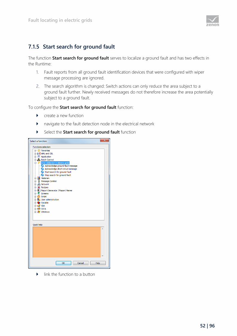
Fault locating in electric grids
52 | 96
7.1.5 Start search for ground fault
The function Start search for ground fault serves to localize a ground fault and has two effects in
the Runtime:
1. Fault reports from all ground fault identification devices that were configured with wiper
message processing are ignored.
2. The search algorithm is changed: Switch actions can only reduce the area subject to a
ground fault further. Newly received messages do not therefore increase the area potentially
subject to a ground fault.
To configure the Start search for ground fault function:
create a new function
navigate to the fault detection node in the electrical network
Select the Start search for ground fault function
link the function to a button

Fault locating in electric grids
53 | 96
7.1.6 Acknowledge ground fault indication
With the Acknowledge ground fault message function, an internally recorded ground fault from a
ground fault indication device can be acknowledged in the Runtime. In doing so, the
internally-latched ground fault status is reset if the status is still pending, or highlighted as
acknowledged. A recorded ground fault message is only deleted internally if this has been
acknowledged and is no longer pending.
Rules when acknowledging:
If a variable that corresponds to a triggering or direction variable of a ground fault
recognition device is linked, this special ground fault indication is acknowledged.
If no variable has been linked, all ground fault indications are acknowledged.
Acknowledgment can also take place via the zenon API object model.
To configure the Acknowledge ground fault message function:
create a new function
navigate to the fault detection node in the electrical network
Select the Acknowledge ground fault message function
the dialog to select a variable opens
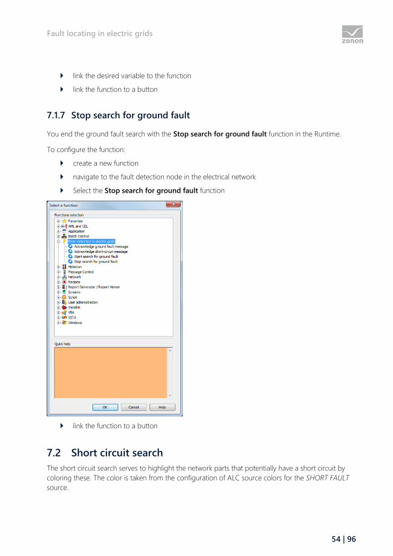
Fault locating in electric grids
54 | 96
link the desired variable to the function
link the function to a button
7.1.7 Stop search for ground fault
You end the ground fault search with the Stop search for ground fault function in the Runtime.
To configure the function:
create a new function
navigate to the fault detection node in the electrical network
Select the Stop search for ground fault function
link the function to a button
7.2 Short circuit search
The short circuit search serves to highlight the network parts that potentially have a short circuit by
coloring these. The color is taken from the configuration of ALC source colors for the SHORT FAULT
source.

Fault locating in electric grids
55 | 96
The network parts that are potentially subject to short circuits are deduced from short circuit reports.
A short circuit identification device (short circuit indicator, protective device) can have one to three
short circuit messages. For directional short circuit indication devices, the direction can be lagging or
leading in relation to triggering. A network component that potentially has a short circuit is then no
longer considered to have a ground fault if this has been successfully connected.
ENGINEERING
To configure the short circuit search:
1. assign the combined element that represents the switching element to the Function type
switch (on page 55)
2. Define ground fault display (on page 56) andtriggering of ground fault detection (on page
56)
3. Set up the function for acknowledgment of ground fault message (on page 57)
7.2.1 Short-circuit recognition type
The direction and type of message processing for the combined element are determined by means of
the Type setting. For project configuration:
1. navigate to the Automatic Line Coloring node in the combined element properties
2. open the node Short-circuit detection
3. Select the desired type in the Type property
Direction:
indicates if the raising edge of trigger indication or if the raising edge of a direction
comes before it
leading:
With rising edge of the trigger indication, the current status of the direction is used.
lagging:
After a rising edge of the trigger indication, the first rising edge of a direction is waited
for,; if this does not occur within 2 seconds, the short circuit identification device is
considered non-directional
Indication processing:
states which indication can be processed
None:
normal switch; indications are not processed
Permanent indication processing:
Newly received indications are considered as new ground fault trip
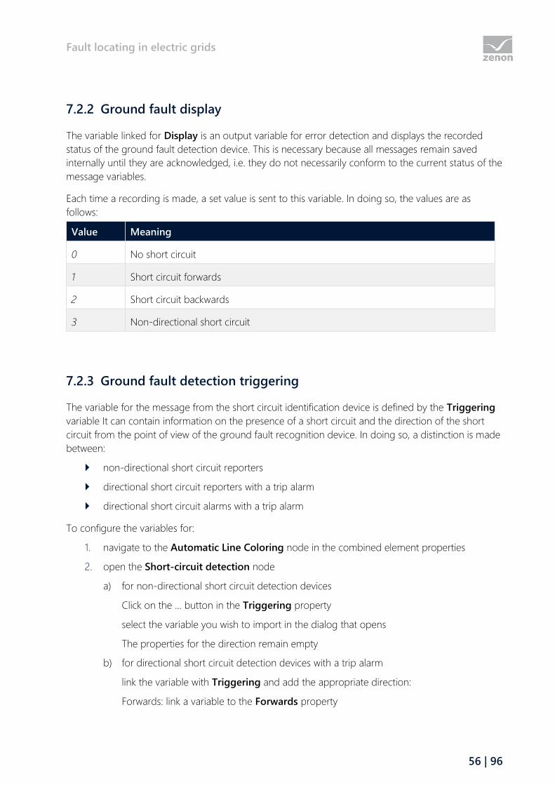
Fault locating in electric grids
56 | 96
7.2.2 Ground fault display
The variable linked for Display is an output variable for error detection and displays the recorded
status of the ground fault detection device. This is necessary because all messages remain saved
internally until they are acknowledged, i.e. they do not necessarily conform to the current status of the
message variables.
Each time a recording is made, a set value is sent to this variable. In doing so, the values are as
follows:
Value Meaning
0 No short circuit
1 Short circuit forwards
2 Short circuit backwards
3 Non-directional short circuit
7.2.3 Ground fault detection triggering
The variable for the message from the short circuit identification device is defined by the Triggering
variable It can contain information on the presence of a short circuit and the direction of the short
circuit from the point of view of the ground fault recognition device. In doing so, a distinction is made
between:
non-directional short circuit reporters
directional short circuit reporters with a trip alarm
directional short circuit alarms with a trip alarm
To configure the variables for:
1. navigate to the Automatic Line Coloring node in the combined element properties
2. open the Short-circuit detection node
a) for non-directional short circuit detection devices
Click on the ... button in the Triggering property
select the variable you wish to import in the dialog that opens
The properties for the direction remain empty
b) for directional short circuit detection devices with a trip alarm
link the variable with Triggering and add the appropriate direction:
Forwards: link a variable to the Forwards property
Fault locating in electric grids
57 | 96
Backwards: link a variable to the Backwards property
c) for directional short circuit detection devices without a trip alarm
Link the variable with the corresponding direction:
Forwards: link a variable to the Forwards property
Backwards: link a variable to the Backwards property
The Triggering property remains empty
7.2.4 Acknowledge short-circuit message
With the Acknowledge short-circuit message function, an internally recorded short circuit from a
short circuit indication device can be acknowledged in the Runtime. In doing so, the internally-latched
ground fault status is reset if the status is still pending, or highlighted as acknowledged. A recorded
short circuit message is only deleted internally if this has been acknowledged and is no longer
pending.
Rules when acknowledging:
If a variable that corresponds to a triggering or direction variable of a short circuit
recognition device is linked, this special short circuit message is acknowledged.
If no variable has been linked, all short circuit messages are acknowledged.
Acknowledgment can also take place via the zenon API object model.
TO CONFIGURE THE ACKNOWLEDGE SHORT-CIRCUIT MESSAGE FUNCTION:
create a new function
navigate to the fault detection node in the electrical network
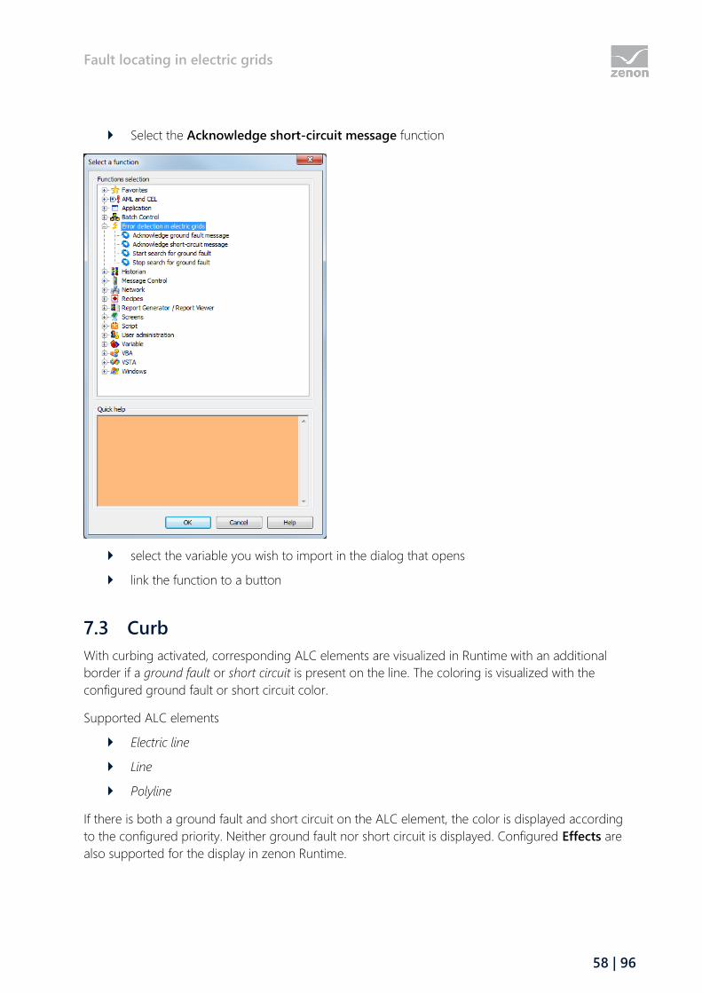
Fault locating in electric grids
58 | 96
Select the Acknowledge short-circuit message function
select the variable you wish to import in the dialog that opens
link the function to a button
7.3 Curb
With curbing activated, corresponding ALC elements are visualized in Runtime with an additional
border if a ground fault or short circuit is present on the line. The coloring is visualized with the
configured ground fault or short circuit color.
Supported ALC elements
Electric line
Line
Polyline
If there is both a ground fault and short circuit on the ALC element, the color is displayed according
to the configured priority. Neither ground fault nor short circuit is displayed. Configured Effects are
also supported for the display in zenon Runtime.

Fault locating in electric grids
59 | 96
ENGINEERING IN THE EDITOR
Carry out the following steps to configure curbing:
Configure the colors for ground fault and short circuit.
To do this, click on the ... button in the ALC configuration property in the Automatic
Line Coloring project properties group.
The ALC configuration dialog is opened.
Amend the colors for the pre-existing GROUND FAULT and SHORT FAULT entries.
To do this, click on the ... button in the line color column. The color is selected from a
drop-down list.
Create or selected a zenon screen in the Editor.
Draw a line, polyline or pipeline or select an existing element.
Activate, in the Automatic Line Coloring project properties group, the Color from ALC
property.
Activate the Use curb property and configure the width of the curbing in the Curb width
[px] property.
NOTE ON CONFIGURATION
The following configuration is recommended for a clean graphic display of the curbing in Runtime:
Draw ALC line elements.
As a result, it is possible that the display of one line protrudes into another.
To clean a graphics defect:
a) Highlight the element that overlaps due to the configuration.
b) Select the Element position entry in the context menu.

Impedance-based fault locating and load distribution calculation
60 | 96
c) Select the Background entry.
The selected element is moved to the background. As a result, the correct display of the line elements
is guaranteed.
8 Impedance-based fault locating and load distribution
calculation
Impedance based fault detection and calculation of load distribution extend the ALC module.
Whereas the ALC base model identifies nodes and beams, this special model also detects lines and
their parameters.
Fault locating from protection is possible by means of configuration in the zenon Editor. Therefore, for
example, the location of the error can be visualized in a zenon screen with a marker.
In addition, this ALC model provides properties and methods for external evaluation of the fault
location and load distribution via API.

Impedance-based fault locating and load distribution calculation
61 | 96
PROPERTIES FOR ALC AND THE EXTENDED TOPOLOGICAL MODEL
The ALC elements Combined element and Line (line, polyline, pipe) have special properties for
impedance-based fault locating and to calculate the load distribution. The properties for the load
distribution calculation is configured in the Editor. The evaluation is not carried out in zenon however,
but is available via the zenon API as algorithms to be created by users.
FILE FOR EXPANDED TOPOLOGICAL MODEL
The simple topological model of the ALC base module for the coloring is supplemented by an
expanded topological model that includes all lines as separate beams. The extended topological
model is stored as ALC.xml and can be read by external applications this way. ALC.xml contains two
sections:
GraphElements:
contains the extended topological model without aliases
GraphAliases:
contains only the aliases
8.1 Impedance-based fault locating of the short circuit
With impedance-based fault locating, an error marker is set at the location of the failure in the
topology. The impedance values measured by protective devices are evaluated by the ALC module.
Based on the topology, the fault markers are positioned in the screen correctly in a zenon screen.
If a short circuit occurs and the reactance is not equal to zero, the search for the location of the short
circuit starts:
Short circuit:
Reported by a linked variable for the Triggering property (Short-circuit detection
properties group of the element).
Reactance:
Value of the variable (from the REAL data type), that is linked to the Reactance value from
protection property (Topological properties properties group of the element) .
Information
Impedance-based causes of error can no longer be applied to mash networks in
this topology.

Impedance-based fault locating and load distribution calculation
62 | 96
POSITION OF THE MARKER
All lines are run through in the corresponding direction. The direction results from negative or
positive reactancy. The respective reactancy of the line run through is deducted and the search
continues until the residual reactancy is less than the reactancy of the next line. A marker is drawn in
the line. The position of the marker corresponds to the residual reactancy.
If there is no reactancy value, no marker is set in the event of a short circuit indication. In order for the
marker to be drawn correctly, the area must not be under load during the short circuit indication.
With lagging short-circuit indications, the reactancy is only evaluated if the notification of direction
has been received or the timeout of 2 seconds has expired.
The search is canceled if an open shift element or another ALC element has been found. Each part of
the network and each individual line therein must only run once per trigger, there are thus less
markers that occur in the line network than would be possible.
When reloading, markers that already exist are drawn at the same point as before reloading. Changes
to the configuration of the fault locating are only evaluated after another short circuit.
If a short circuit indication is removed and acknowledged, all markers of this short circuit trigger are
deleted.
Note: Depending on the order of the rectification of the short circuit and switching on again, marker
can remain drawn in, although the line is no longer colored as a short circuit.
8.2 Load distribution calculation
With impedance-based fault locating, an error marker is set at the location of the failure in the
topology. The location is calculated from impedance, on the basis of the expanded topology.
To configure the impedance-based fault location in the zenon Editor, carry out the following steps:
1. Activate impedance-based fault location:
a) To do this, click on the project in your Workspace.
a) Click on the Automatic Line Coloring project property group.
b) Activate property Fault location based on impedance.
Optional:
Configure the Maximum acceptable current overload [%] of the line.
Configure the setting for the line overload interlocking in the ALC configuration
property. This interlocking is not activated by default.
2. Configure the display of the screen markers with the project properties:
a) Screen marker size

Impedance-based fault locating and load distribution calculation
63 | 96
b) Line width of the screen marker
c) Display type of the screen marker
3. Create a zenon screen.
4. Position the combined element on the zenon screen.
The variable selection dialog is opened.
5. Configure the ALC settings for the combined element:
a) Ensure that the combined element has been selected.
b) Switch to the Automatic Line Coloring property group.
c) In the Function type property, select the Switch entry from the drop-down list.
d) Link the Reactance value from protection property (in the Topological properties
properties section) to a REAL data type variable with the value of the measured
impedance.
e) Select the type of Short-circuit detection in the drop-down list of the Type property.
f) Configure the color of the marker in the Marker color property.
8.3 Expanded topological model
Each object has a unique ID, via which it is referenced in the file. The attributes correspond to a
subset of the zenon screen elements that have created the elements.
GRAPHELEMENT
ID Description
Picture Screen name
ElementID Screen element ID
ElementRef Screen element reference
Type Screen element -type (see "element")
SourceID Source number
ReverseSourceID Source name in reverse direction
Variable Status variable
VarProtReact Reactance variable
MaxIType Type of maximum current
MaxIVal Maximum current constant value
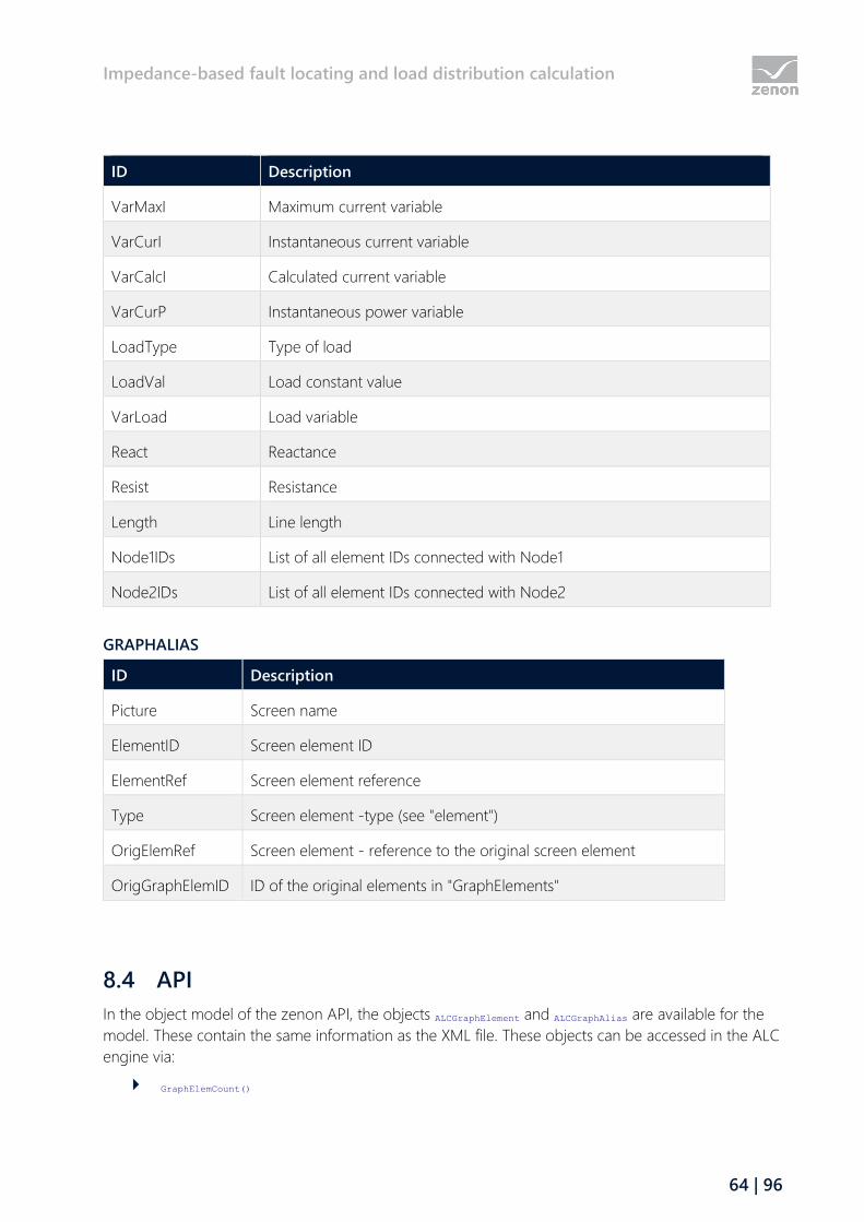
Impedance-based fault locating and load distribution calculation
64 | 96
ID Description
VarMaxI Maximum current variable
VarCurI Instantaneous current variable
VarCalcI Calculated current variable
VarCurP Instantaneous power variable
LoadType Type of load
LoadVal Load constant value
VarLoad Load variable
React Reactance
Resist Resistance
Length Line length
Node1IDs List of all element IDs connected with Node1
Node2IDs List of all element IDs connected with Node2
GRAPHALIAS
ID Description
Picture Screen name
ElementID Screen element ID
ElementRef Screen element reference
Type Screen element -type (see "element")
OrigElemRef Screen element - reference to the original screen element
OrigGraphElemID ID of the original elements in "GraphElements"
8.4 API
In the object model of the zenon API, the objects ALCGraphElement and ALCGraphAlias are available for the
model. These contain the same information as the XML file. These objects can be accessed in the ALC
engine via:
GraphElemCount()

Impedance-based fault locating and load distribution calculation
65 | 96
GraphAliasCount()
GraphElemItem()
GraphAliasItem()
USER-SPECIFIC TOPOLOGICAL INTERLOCKINGS
If a topological interlocking is checked, the following event is called up at the ALC engine:
void CheckInterlocking(IALCEdge* pALCEdge, long nNewState, tpLockResult* LockResult, BSTR* bsText, VARIANT_BOOL*
bUnlockable);
The switch/disconnector to be switched and the new status is transferred. The event can fill LockResult,
bUnlockable and bsText in order to display a violated interlocking condition. If the event handler returns
tpBusy in LockResult, the event handler is queried until it no longer provides tpBusy, however for a
maximum of 10 seconds. The interlocking is active after 10 seconds. The interlocking text and
unlockability are reported back in bsText and bUnlockable.
SCREEN MARKER
Marker elements can be inserted into screens via the zenon API. These marker elements are available
for the following elements:
Line
Polyline
Pipe
These are added or deleted via the API functions in DynPictures:
BSTR AddMarker(BSTR bsScreenName, long nElementID, short nPosition, short nLineColorIndex, short nFillColorIndex);
VARIANT_BOOL DelMarker(BSTR bsID);
The GUID of the marker, which is supplied by AddMarker(), identifies the marker uniquely and serves
as both the element name (with the prefix "$MARKER_") as well as the key for deletion via DelMarker().
The markers inserted via API are saved in the project according to the screen. Attention: Saving is
not remanant, i.e. only until Runtime is restarted.
The markers set there are displayed regardless of the monitor on which the screen is opened. The
markers are treated internally as normally operable screen elements. Mouse events are called up for
this.
The appearance of the markers is set using the project settings in the Automatic Line Coloring area
of the project configuration:
Display type of the screen marker: Triangle, circle, square, cross
Screen marker size: Size in pixels:
Line width of the screen marker: Width in pixels
Load flow calculation
66 | 96
Marker color: is defined via the index in the marker color table (on page 40), that is located in
the properties of the screen elements in the Automatic Line Coloring group
9 Load flow calculation
The Load Flow Calculation module implements the following functionality:
Calculation for 3-phase, high-performance energy networks.
Derivation of the load flow model from screens with ALC elements (active elements, closed
switches etc.)
Calculation of the load flow for the current model status (from the values of the ALC
elements).
Topological interlockings, based on advance calculation of the ALC model.
(n-1) calculation.
Visualization of a possible network overload, for example in the event of a failure of a line.
The configuration is carried out in the zenon Editor by setting the parameters of ALC properties for
the corresponding screen elements (combined elements, line, ...). The parameters for these
configurations of the load flow calculation are set in the corresponding properties for ALC screen
elements (on page 68) in zenon Editor.
In zenon Runtime, the calculation (on page 87) is carried out on the basis of the Newton-Raphson
method for iterative and approximative solution of non-linear equation systems. The problem is set
with complex values: applicable for N bars, of which G with generators, is 2N - G - 1 real unknown
(voltage on the load bars, phase of the bars). The nominal voltage without phase moving is assumed
as a starting value.
The results of the load flow calculation are output to the variables that are linked at the respective
ALC element. This configuration continues to serve as a basis for subsequent (n-1) calculations. The
result of this calculation can be visualized with the "load flow (n-1) calculation" screen type in Runtime.
9.1 General
The topological network was displayed with the help of ALC elements.
A requirement for the load flow calculation is that the topological network is configured with the help
of ALC elements. A zenon screen (single-phase or three-phase ALC single line screen) with combined
elements and lines must be present. The properties relevant for load flow calculation must be
configured correctly for these screen elements.
The load flow calculation determines:

Load flow calculation
67 | 96
For consuming devices (loads)
The voltage and the phase.
For generators
The reactive power and the phase.
For lines
Current (average value)
Power factor
Voltage at the input and output
Active power at the input and output
Reactive power at the input and output
For transformers:
Current at the input and output
Voltage at the input and output
Active power at the input and output
Reactive power at the input and output
The values calculated this way can be output to variables that are linked to ALC elements.
The current can also be given as an alternative to power: I = S/U. This is not necessary if the current is
already available via linked variables.
The load flow is calculated using the connection branches between the busbars. to do this, the
generators, transformers and loads are assigned to the bars and the branches (also parallel) are
formed from the lines and switches. Lines with zero impedance are integrated into the busbars.
REQUIRED MEASURED VALUES
The following measured values are necessary for the input of the load flow calculation:
For generators and sources:
The active power and the voltage.
A generator is the reference for the phase; the active power is also calculated for it.
Note: Sources do not have output values that can be calculated.
For consuming device (loads)
The active power and reactive power.
For transformers:
The coil ratio and the phase shift.
The parameters for nominal power [MW], power loss, magnetization losses, stepped switches
and phase shift can be set in the Editor.

Load flow calculation
68 | 96
For lines:
The complex impedance (resistance and reactance).
For capacitors:
Increment (s), interconnection (v) and position (i).
This results in the applied reactive power as a measured value: Q = s*v[i].
Note: Only active elements are taken into account.
9.2 Requirements
It is recommended that the load flow calculation is carried out on a powerful computer with a 64-bit
operating system.
With the ALC elements, there must be sufficient variables linked to measured values.
9.3 Engineering in the Editor
Configuration steps for the Load Flow Calculation module:
1. Activate the Load flow calculation.
a) Go to the Automatic Line Coloring property group in the project properties.
a) In the Activate load flow calculation property, select the Load Flow entry from the
drop-down menu.
2. Set the parameters for existing ALC screen elements.
The setting of the parameters for the load flow calculation is configured in the following
properties of the ALC screen elements for the Automatic Line Coloring properties group.
Note also the information in the property help for the respective properties.
The availability depends on the configured Function type of the ALC element.
ALC screen element Combined element
Function type Source:
Load flow calculation - input
a) Function type Generator:
Load flow calculation - input
Load flow calculation output
b) Function type Drain:
Load flow calculation - input
Load flow calculation output
Load flow calculation
69 | 96
c) Function type Transformer:
Load flow calculation transformer input
Load flow calculation transformer output
Note also the configuration notes in chapter three-coil transformer (on page 70).
d) Function type Capacitor:
Capacitor
ALC screen element Line or pipe:
Load flow line parameter
Load flow line result
3. Link the ALC screen element to variables that provide measured values from the process.
Example: A PLC provides the current value of the active power of a generator. You link the
variables for this measured value in the combined element with which you display this
generator in the topological network. You configure this linking in the Load flow calculation
- input properties group for the Active power dynamic [MW] property.
4. Link the ALC screen element to variables in which the result of the load flow calculation is
written.
You can use internal driver variables to do this. You can use these variables in zenon screens
to display the output values.
Note: Note the Configuration of the output parameters (on page 73) chapter.
CONFIGURATION STEPS FOR (N-1) CALCULATION
1. Carry out the configuration steps for the Load flow calculation.
2. Activate the (n-1) calculation.
a) Go to the Automatic Line Coloring property group in the project properties.
b) Activate property Activate (n-1) calculation.
3. Configure a zenon Load flow (n-1) calculation screen.
You can find further information on this in the Screen of type Load flow (n-1) calculation (on
page 74) chapter.
4. Configure a function Screen switch.
Information
If command input is used in the project, a line overload (on page 34) topological
interlocking can also be configured.
Load flow calculation
70 | 96
9.3.1 Transformers
The ratio of the coil numbers of a transformer correspond to the ratio of the primary voltage to
secondary voltage. The information about voltage is gained from the ALC configuration of the
source colors and the parameters for this do not also need to be set up separately.
Attention
A transformer must be configured for load-flow calculation with:
Nominal output [MW] > 0
Loss reactive power [MVar] > 0
If the transformer does not have tap changing, the properties minimum tap change = maximum
tap change = nominal tap change = 1 should be configured; the tap change increment can be
0%. The transformer thus remains configured to 100% nominal output.
Note: If there are voltages due to deviations from the ratio as a result of the construction type, the
difference can be given as increment. You can thus set the parameters of the transformer in such a
way that it always remains at one stage next to the nominal.
TRANSFORMER WITH TAP CHANGE
Tap changer of the power transformers are for dynamic changes to the transmission ratios. In order
to take the tap change into account, the following settings should be set for load flow calculation:
Minimum tap change - the lowest level.
Maximum tap change - the highest level.
Nominal - the level at which the transformer provides the secondary nominal voltage.
It is the level at which the voltage ratio is equal primary voltage and secondary voltage; and
equal to 100%.
Tap-change increment [%] - percentage indication of the increment per level, based on
nominal = 100% - upwards and downwards.
Current position tap change - a variable that provides the current position of the tap
change from the process; for example, a 'step position information' of the IEC870 driver or
*/TapChg/stVal[ST] of the IEC850.
Example:
A transformer with 380 kV primary voltage and 110 kV secondary voltage:
200 MW nominal output
Minimum tap change = 1
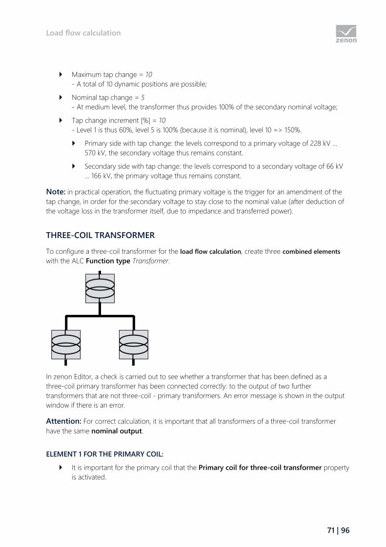
Load flow calculation
71 | 96
Maximum tap change = 10
- A total of 10 dynamic positions are possible;
Nominal tap change = 5
- At medium level, the transformer thus provides 100% of the secondary nominal voltage;
Tap change increment [%] = 10
- Level 1 is thus 60%, level 5 is 100% (because it is nominal), level 10 => 150%.
Primary side with tap change: the levels correspond to a primary voltage of 228 kV …
570 kV, the secondary voltage thus remains constant.
Secondary side with tap change: the levels correspond to a secondary voltage of 66 kV
… 166 kV, the primary voltage thus remains constant.
Note: in practical operation, the fluctuating primary voltage is the trigger for an amendment of the
tap change, in order for the secondary voltage to stay close to the nominal value (after deduction of
the voltage loss in the transformer itself, due to impedance and transferred power).
THREE-COIL TRANSFORMER
To configure a three-coil transformer for the load flow calculation, create three combined elements
with the ALC Function type Transformer.
In zenon Editor, a check is carried out to see whether a transformer that has been defined as a
three-coil primary transformer has been connected correctly: to the output of two further
transformers that are not three-coil - primary transformers. An error message is shown in the output
window if there is an error.
Attention: For correct calculation, it is important that all transformers of a three-coil transformer
have the same nominal output.
ELEMENT 1 FOR THE PRIMARY COIL:
It is important for the primary coil that the Primary coil for three-coil transformer property
is activated.

Load flow calculation
72 | 96
Link the variables for the result of the load flow calculation in the Load flow calculation
transformer output properties group in the properties for the inputs:
Current Input [A]
Voltage input [kV]
Active power input [MW]
Reactive power input [MVar]
Note: The primary transformer should also have a source color for ALC.
ELEMENT 2 AND 3 FOR THE SECONDARY AND TERTIARY COIL:
When configuring the secondary and tertiary coil, it is important that the Primary coil for
three-coil transformer property is not activated.
Link the variables for the result of the load flow calculation in the Load flow calculation
transformer output properties group in the properties for the outputs:
Current Output [A]
Voltage output [kV]
Active power output [MW]
Reactive power output [MVar]
INTERACTION OF THE CONFIGURED PARAMETERS FOR A THREE-COIL TRANSFORMER
The three-coil transformer only uses increments from the primary transformer (and ignores them for
the secondary transformers). The phase shift is only evaluated by the secondary transformers. The
losses correspond to the transformer's data sheet or the following calculation: Nominal voltage
multiplied by the short circuit voltage [%] / 100.
With secondary transformers, power losses are stated in relation to the primary coil. The losses
between the secondary and the tertiary coil are taken into account when calculating the triangle with
the primary transformer.
Magnetization losses are only taken into account by the primary coil.
For correct calculation, it is important that all transformers of a three-coil transformer have the same
nominal output.
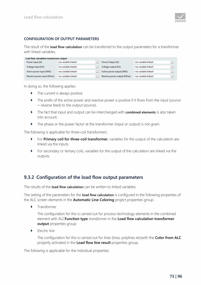
Load flow calculation
73 | 96
CONFIGURATION OF OUTPUT PARAMETERS
The result of the load flow calculation can be transferred to the output parameters for a transformer
with linked variables.
In doing so, the following applies:
The current is always positive.
The prefix of the active power and reactive power is positive if it flows from the input (source
= reverse feed) to the output (source).
The fact that input and output can be interchanged with combined elements is also taken
into account.
The phase or the power factor at the transformer (input or output) is not given.
The following is applicable for three-coil transformers:
For Primary coil for three-coil transformer, variables for the output of the calculation are
linked via the inputs.
For secondary or tertiary coils, variables for the output of the calculation are linked via the
outputs.
9.3.2 Configuration of the load flow output parameters
The results of the load flow calculation can be written to linked variables.
The setting of the parameters for the load flow calculation is configured in the following properties of
the ALC screen elements in the Automatic Line Coloring project properties group .
Transformer
The configuration for this is carried out for process-technology elements in the combined
element with ALCFunction type transformer in the Load flow calculation transformer
output properties group
Electric line
The configuration for this is carried out for lines (lines, polylines etc)with the Color from ALC
property activated in the Load flow line result properties group.
The following is applicable for the individual properties:

Load flow calculation
74 | 96
Name Unit Range of
values
Formula
Current Amperes I ≥ 0,0 I = (VOn - VOff) / Z / √3
Power factor None 0,0 ≤ cos φ ≤
1,0
cos φ = P / S =
P / √(P^2+Q^2)
Voltage input kV U ≥ 0,0 VOn
Voltage output kV U ≥ 0,0 VOff
Active power input MW POff + jQOn = VOn *ΔV / Z
Reactive power input MVar
Active power output MW POff + jQOff = VOff *ΔV / Z
Reactive power output MVar
OUTPUT OF VALUES
All calculated values are output at each component (line or transformer) on a path.
The following is applicable for this:
The input is at the top-left (if the line is exactly diagonal, the input is at the top right).
The power is positive if the flow is from the input to the output.
Active power or reactive power at the input and output have the same prefix.
The loss as POn - POff or QOn - QOff is therefore always ≥ 0.0.
Active and reactive power of a line can have a different prefix.
Current, voltage and power factor are always positive.
The current along a path (with overall impedance Z) is constant.
The power factor is always determined at the output.
If a line has no impedance, the values at the input and output are the same.
If a line is part of a busbar, only the current voltage at the input and output is given.
9.4 Screen type Load flow (n-1) calculation
The new Load flow (n-1) calculation screen type visualizes the calculated "N-1" scenario in Runtime, for
example a possible network overload in the event of a failure of a line.

Load flow calculation
75 | 96
A line or a transformer is removed from the network for the (n-1) calculation. The Load Flow
Calculation module calculates the resultant load for the other components (lines and transformers) in
this network and visualizes the consequences. This is determined for all lines and transformers.
The list in the screen can serve to find the part of a path that is under most load (line or transformer,
line load column) after a component is taken from the network (line failure). The load from line
failure that is displayed is in relation to the probability with which the component could fail. A
switching (or failure) in the area of line failure would lead to a transfer of the load flow to line load.
ENGINEERING
Two procedures are available to create a screen:
The use of the screen creation dialog
The creation of a screen using the properties
Steps to create the screen using the properties if the screen creation dialog has been deactivated in
the menu bar under Tools, Settings and Use assistant:
1. Create a new screen.
To do this, select the New screen command in the tool bar or in the context menu of the
Screens node.
2. Change the properties of the screen:
a) Name the screen in the Name property.
b) Select load flow (n-1) calculation in the Screen type property.
c) Select the desired frame in the Frame property.
3. Configure the content of the screen:
a) Select the Elements (screen type) menu item from the menu bar.
b) Select Insert template in the drop-down list.
The dialog to select pre-defined layouts is opened. Certain control elements are inserted
into the screen at predefined positions.
c) Remove elements that are not required from the screen.
d) If necessary, select additional elements in the Elements drop-down list. Place these at the
desired position in the screen.
4. Create a screen switch function.
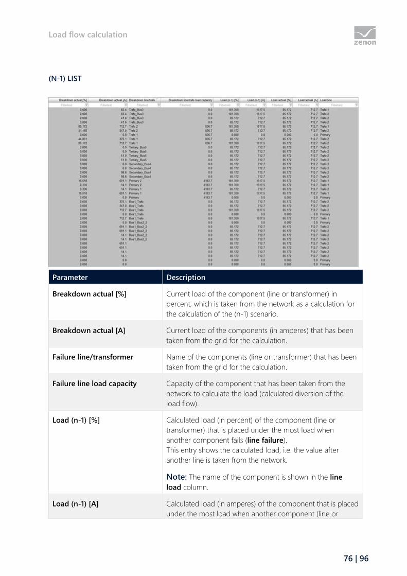
Load flow calculation
76 | 96
(N-1) LIST
Parameter Description
Breakdown actual [%] Current load of the component (line or transformer) in
percent, which is taken from the network as a calculation for
the calculation of the (n-1) scenario.
Breakdown actual [A] Current load of the components (in amperes) that has been
taken from the grid for the calculation.
Failure line/transformer Name of the components (line or transformer) that has been
taken from the grid for the calculation.
Failure line load capacity Capacity of the component that has been taken from the
network to calculate the load (calculated diversion of the
load flow).
Load (n-1) [%] Calculated load (in percent) of the component (line or
transformer) that is placed under the most load when
another component fails (line failure).
This entry shows the calculated load, i.e. the value after
another line is taken from the network.
Note: The name of the component is shown in the line
load column.
Load (n-1) [A] Calculated load (in amperes) of the component that is placed
under the most load when another component (line or
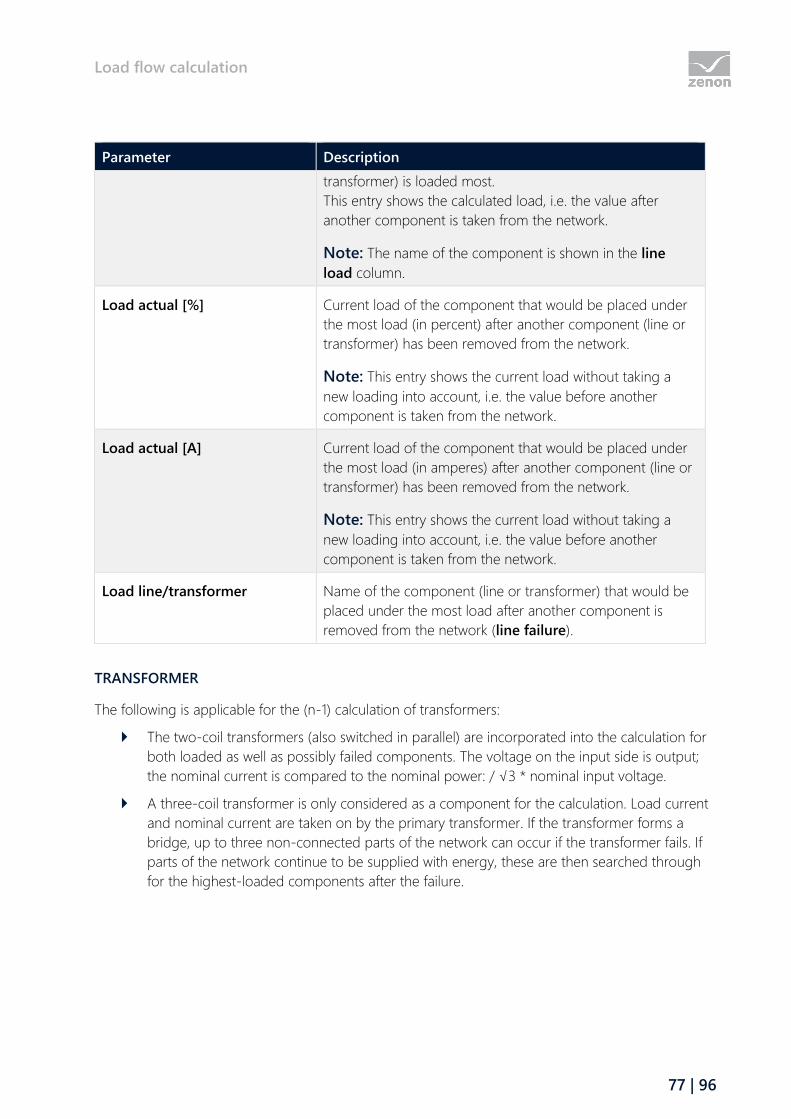
Load flow calculation
77 | 96
Parameter Description
transformer) is loaded most.
This entry shows the calculated load, i.e. the value after
another component is taken from the network.
Note: The name of the component is shown in the line
load column.
Load actual [%] Current load of the component that would be placed under
the most load (in percent) after another component (line or
transformer) has been removed from the network.
Note: This entry shows the current load without taking a
new loading into account, i.e. the value before another
component is taken from the network.
Load actual [A] Current load of the component that would be placed under
the most load (in amperes) after another component (line or
transformer) has been removed from the network.
Note: This entry shows the current load without taking a
new loading into account, i.e. the value before another
component is taken from the network.
Load line/transformer Name of the component (line or transformer) that would be
placed under the most load after another component is
removed from the network (line failure).
TRANSFORMER
The following is applicable for the (n-1) calculation of transformers:
The two-coil transformers (also switched in parallel) are incorporated into the calculation for
both loaded as well as possibly failed components. The voltage on the input side is output;
the nominal current is compared to the nominal power: / √3 * nominal input voltage.
A three-coil transformer is only considered as a component for the calculation. Load current
and nominal current are taken on by the primary transformer. If the transformer forms a
bridge, up to three non-connected parts of the network can occur if the transformer fails. If
parts of the network continue to be supplied with energy, these are then searched through
for the highest-loaded components after the failure.

Load flow calculation
78 | 96
9.4.1 Engineering in the Editor
The load flow N-1 calculation screen is to visualize current loads of a component (line or transformer)
as well as calculated loads on components (line or transformer). The calculated loads show the values
of a component with the assumption that another component of the mesh network is no longer
present.
ENGINEERING
Two procedures are available to create a screen:
The use of the screen creation dialog
The creation of a screen using the properties
Steps to create the screen using the properties if the screen creation dialog has been deactivated in
the menu bar under Tools, Settings and Use assistant:
1. Create a new screen.
To do this, select the New screen command in the tool bar or in the context menu of the
Screens node.
2. Change the properties of the screen:
a) Name the screen in the Name property.
b) Select load flow (n-1) calculation in the Screen type property.
c) Select the desired frame in the Frame property.
3. Configure the content of the screen:
a) Select the Elements (screen type) menu item from the menu bar.
b) Select Insert template in the drop-down list.
The dialog to select pre-defined layouts is opened. Certain control elements are inserted
into the screen at predefined positions.
c) Remove elements that are not required from the screen.
d) If necessary, select additional elements in the Elements drop-down list. Place these at the
desired position in the screen.
4. Create a screen switch function.
9.5 Screen switching for the load flow (n-1) calculation
To open a Load flow (n-1) calculation screen in the Runtime:
1. Configure a screen of type Load flow (n-1) calculation (on page 74).

Load flow calculation
79 | 96
2. Create a function Screen switch for this screen.
3. Define the desired column settings.
CREATE A SCREEN SWITCH FUNCTION
A Screen switch function is for calling up screens in the Runtime. You can configure the graphical
appearance of the list for screen switching to a load flow (n-1) calculation screen.
ENGINEERING
Steps to create the function:
1. Create a new function:
In the toolbar or in the context menu of the Functions node, select New function.
The dialog to select a function is opened.
2. Navigate to node Screens
3. Select the Screen switching function
The dialog for selecting a screen is opened.
4. Select the desired screen.
Note: If you select a screen from another project, ensure that the project is running in the
Runtime.
5. Confirm your selection by clicking on the OK button.
The Filter dialog to configure the graphical appearance of the display in Runtime is opened.
6. Click on the column selection (on page 81) button and configure the content that you want
to display in Runtime.
7. Click on the column format (on page 82) button and configure the appearance of the list in
the Runtime.
8. Name the function in the Name property.
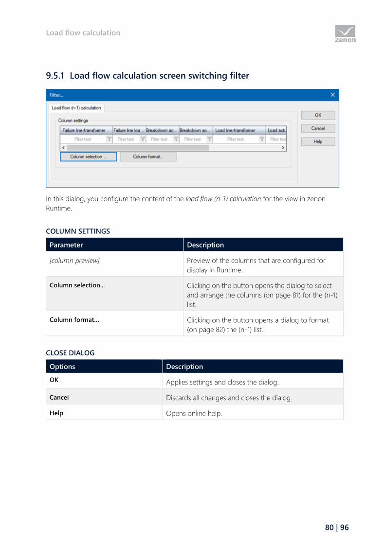
Load flow calculation
80 | 96
9.5.1 Load flow calculation screen switching filter
In this dialog, you configure the content of the load flow (n-1) calculation for the view in zenon
Runtime.
COLUMN SETTINGS
Parameter Description
[column preview] Preview of the columns that are configured for
display in Runtime.
Column selection... Clicking on the button opens the dialog to select
and arrange the columns (on page 81) for the (n-1)
list.
Column format… Clicking on the button opens a dialog to format
(on page 82) the (n-1) list.
CLOSE DIALOG
Options Description
OK Applies settings and closes the dialog.
Cancel Discards all changes and closes the dialog.
Help Opens online help.
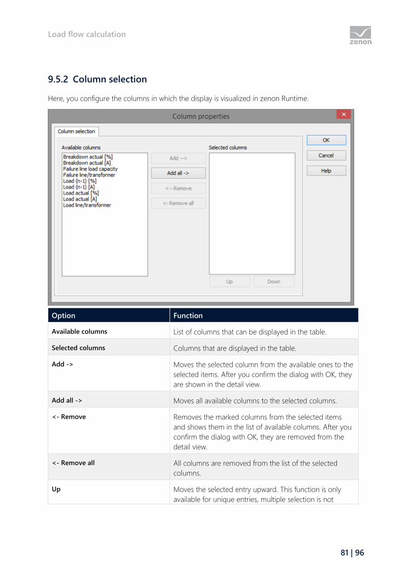
Load flow calculation
81 | 96
9.5.2 Column selection
Here, you configure the columns in which the display is visualized in zenon Runtime.
Option Function
Available columns List of columns that can be displayed in the table.
Selected columns Columns that are displayed in the table.
Add -> Moves the selected column from the available ones to the
selected items. After you confirm the dialog with OK, they
are shown in the detail view.
Add all -> Moves all available columns to the selected columns.
<- Remove Removes the marked columns from the selected items
and shows them in the list of available columns. After you
confirm the dialog with OK, they are removed from the
detail view.
<- Remove all All columns are removed from the list of the selected
columns.
Up Moves the selected entry upward. This function is only
available for unique entries, multiple selection is not

Load flow calculation
82 | 96
Option Function
possible.
Down Moves the selected entry downward. This function is only
available for unique entries, multiple selection is not
possible.
CLOSE DIALOG
Options Description
OK Applies settings and closes the dialog.
Cancel Discards all changes and closes the dialog.
Help Opens online help.
9.5.3 Column format
Configuration of the properties of the columns for configurable lists. The settings have an effect on
the respective list in the Editor or - when configuring screen switching - in Runtime.
AVAILABLE COLUMNS
Option Description
Available columns List of the available columns via Column selection. The
highlighted column is configured via the options in the
Settings area.

Load flow calculation
83 | 96
SETTINGS
Option Description
Settings Settings for selected column.
Labeling Name for column title.
The column title is online language switchable. To do this,
the @ character must be entered in front of the name.
Width Width of the column in characters.
Calculation: Number time average character width of the
selected font.
Alignment Alignment. Selection by means of radio buttons.
Possible settings:
Left: Text is justified on the left edge of the column.
Centered: Text is displayed centered in the
column.
Right: Text is justified on the right edge of the
column.
User-defined colors Properties in order to define user-defined colors for text
and background. The settings have an effect on the Editor
and Runtime.
Note:
These settings are only available for configurable
lists.
In addition, the respective focus in the list can be
signalized in the Runtime by means of different text
and background colors. These are configured using
the project properties.
User defined colors Active: User-defined colors are used.
Text color Color for text display. Clicking on the color opens the
color palette to select a color.
Background color Color for the display of the cell background. Clicking on
the color opens the color palette to select a color.
Lock column filter in the Runtime Active: The filter for this column cannot be changed
in the Runtime.
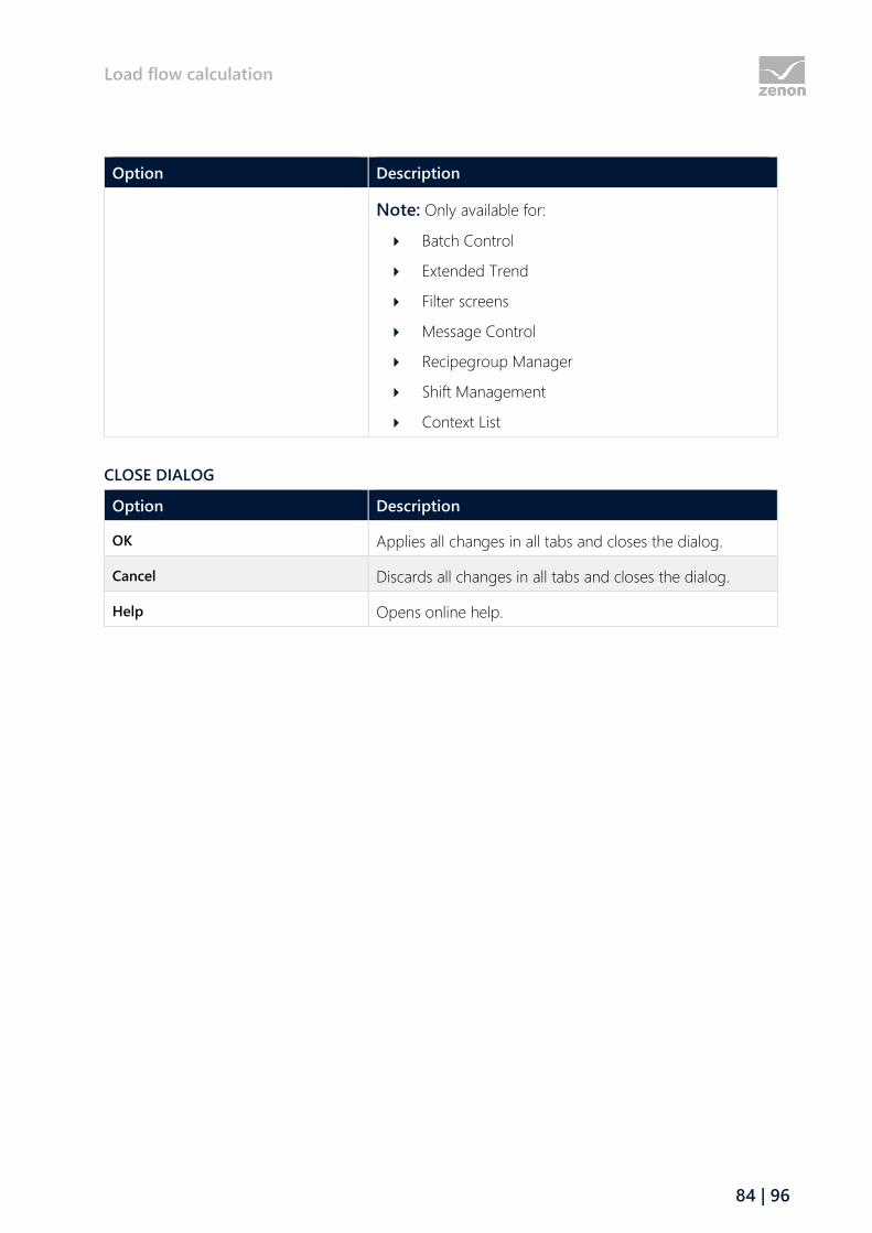
Load flow calculation
84 | 96
Option Description
Note: Only available for:
Batch Control
Extended Trend
Filter screens
Message Control
Recipegroup Manager
Shift Management
Context List
CLOSE DIALOG
Option Description
OK Applies all changes in all tabs and closes the dialog.
Cancel Discards all changes in all tabs and closes the dialog.
Help Opens online help.

Load flow calculation
85 | 96
9.6 Operation in Runtime
If you want to edit the list directly using the monitor, activate the Multi-Touch functionality.
You can find detailed information in relation to this in the Configure interactions chapter.
The following is applicable for the operation of the load flow (n-1) calculation screen in zenon
Runtime:
The list can be sorted
Click for the sorting on the column heading.
The sorting sequence is visualized with an arrow symbol next to the column heading:
Arrow upwards: ascending sorting
Arrow downwards: descending sorting
Another click on the column heading reverses the sorting order.
The list can be filtered
To filter the list:
Enter the desired filter term in the input field below the heading. The default description
of an empty field is filter text (shown in gray font).
DISPLAY OF LONGER TEXTS IN THE LIST
Longer texts can also be displayed in the Runtime over several lines using the Automatic word wrap
property.
In the Editor, go to Representation in the properties of the respective list properties and activate the
checkbox of the Automatic word wrap property.
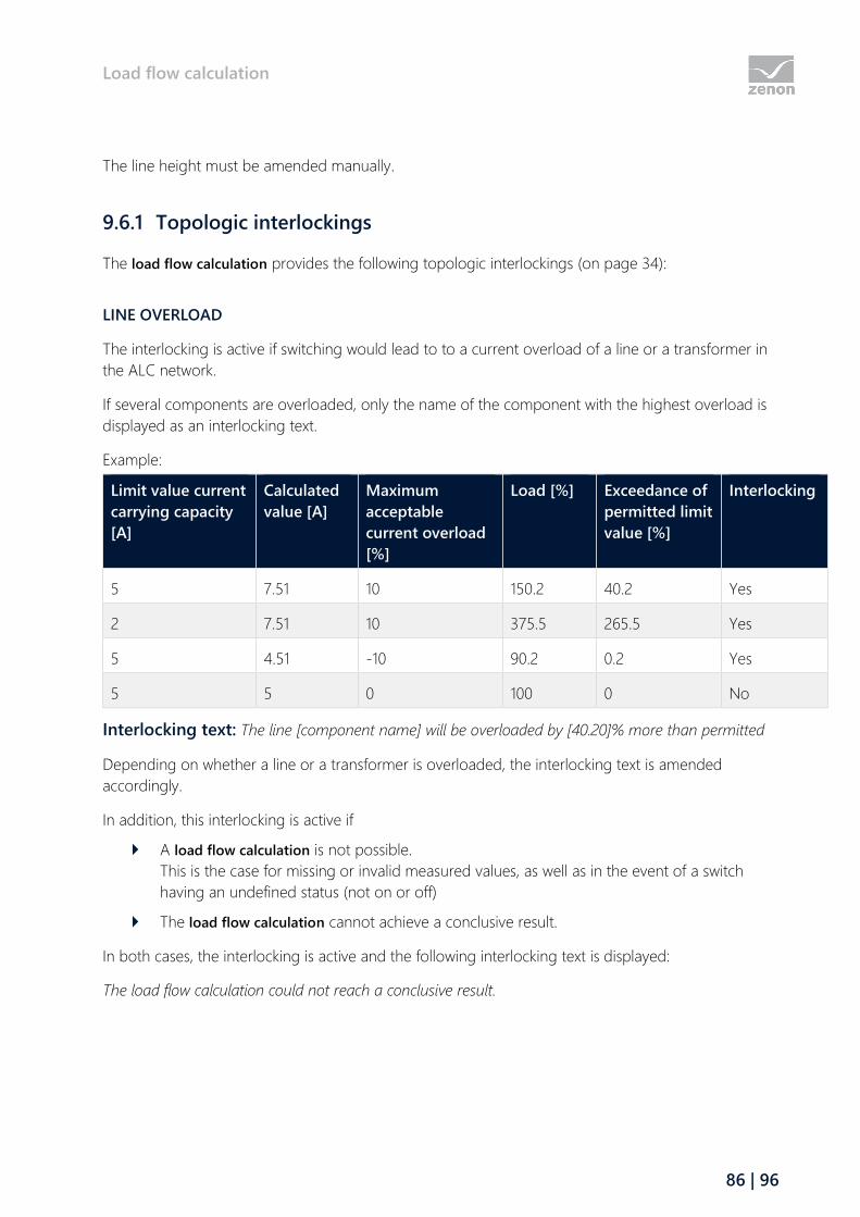
Load flow calculation
86 | 96
The line height must be amended manually.
9.6.1 Topologic interlockings
The load flow calculation provides the following topologic interlockings (on page 34):
LINE OVERLOAD
The interlocking is active if switching would lead to to a current overload of a line or a transformer in
the ALC network.
If several components are overloaded, only the name of the component with the highest overload is
displayed as an interlocking text.
Example:
Limit value current
carrying capacity
[A]
Calculated
value [A]
Maximum
acceptable
current overload
[%]
Load [%] Exceedance of
permitted limit
value [%]
Interlocking
5 7.51 10 150.2 40.2 Yes
2 7.51 10 375.5 265.5 Yes
5 4.51 -10 90.2 0.2 Yes
5 5 0 100 0 No
Interlocking text: The line [component name] will be overloaded by [40.20]% more than permitted
Depending on whether a line or a transformer is overloaded, the interlocking text is amended
accordingly.
In addition, this interlocking is active if
A load flow calculation is not possible.
This is the case for missing or invalid measured values, as well as in the event of a switch
having an undefined status (not on or off)
The load flow calculation cannot achieve a conclusive result.
In both cases, the interlocking is active and the following interlocking text is displayed:
The load flow calculation could not reach a conclusive result.
Load flow calculation
87 | 96
INTERCONNECT VARIOUS VOLTAGE LEVELS
The interlocking is active if switching actions lead to an interconnection of two ALC network areas with
different nominal voltages of the ALC sources.
INTERCONNECT GRIDS
The interlocking is active if switching actions lead to an interconnection of two ALC network areas with
different generators. Process-technical generator elements with different numbers of sources are
considered different generators.
The interlocking is active under the following preconditions:
Both sides of the element are live after switching.
One page contains a generator source that is not present in the other network.
Information
You can find further details on topologic interlockings in the Configuration of the
topologic interlocking (on page 34) in this manual.
9.6.2 View in zenon Runtime
9.7 Calculation
The calculation is carried out on the basis of the Newton-Raphson method for iterative and
approximative solution of non-linear equation systems. The problem is set with complex values:
applicable for N bars, of which G with generators, is 2N - G - 1 real unknown (voltage on the load
bars, phase of the bars). The nominal voltage without phase moving is assumed as a starting value.
The iterative calculations of the Jacobian matrix and results are repeated until the L2 norm of the
correction vector is less than one thousandth.
VALIDATION
When compiling the Runtime files in zenon Editor, a consistency check of the ALC configuration is
carried out. Error notices are displayed in the Editor's output window.
The analysis is carried out in several steps:
First the network, starting form the sources and generators, is searched through.
The search is continued for a switch, disconnector, valve and check valve.
Load flow calculation
88 | 96
The search is ended with end elements (consuming device, capacitor, end element) and
transformer.
All sources that are found in the process are in the same network segment. With a
transformer - depending on the side - the source or the source for reverse feed is taken into
account.
All transformers that have only been taken into account on one side during the first stage of
the search are the starting point for renewed network investigation on the side that has not
been taken into account.
In doing so, the search takes the defined voltage into account, not the source ID.
System sources are not taken into account during this search.
Note that this output is always applicable for the last zenon screen. The sequence of the screens
results from the basis of the topological model. After correction of this configuration error, it is
recommended that the messages in the output window are heeded once again. You can find further
information on the output messages in the Warning messages and LOG entries (on page 91) chapter.
9.7.1 Busbars and branches
IDENTIFICATION AND VALIDATION OF THE BUSBARS
At the start of the load flow calculation, the busbar model is built up from the current topological
model and the switch positions or conditions and loads of sources.
After identification of the busbars, a check is carried out to see whether they meet the minimum
requirements for the load flow. If the requirements are not met, these busbars are removed from the
model.
Minimum requirements:
The busbar determined for a generator must provide a positive net power: Power of the
generator less power of the loads.
Active busbars must have an outgoing connection for sources and generators.
There must be an incoming connection for drains.
Passive busbars must have at least two connections.
If a busbar is removed, this is logged in the LOG file.
VERIFICATION OF JUNCTIONS
The strongest bar of the busbars with generators is selected as a reference bar (slack-bus). All busbars
connected to the reference bar are combined into a partial network. The network is subdivided into
zones with the same voltage by transformers. The partial networks are numbered consecutively. As a
result, all generator bars are assigned to a network.

Load flow calculation
89 | 96
In doing so, the voltage requirement must be met (by the source, generator, transformer or line)
without contradictions. The network cannot be calculated if this is not the case. In the event of a fault,
a warning message is generated in the LOG file for each busbar.
TRANSFER INTO THE CALCULATION MATRIX
For each partial network that contains at least one load bus, the per-unit system is created, arranged
according to voltage and output of the reference bar. The complex admittance values of the existing
connections are incorporated into the calculation matrix. In addition, the known values for PQ or PV
are also applied. All unknown values are considered as 0.
9.7.2 Calculation of the electrical sizes
The reactive power of all generator bars and the active power of the reference bar are calculated. The
calculated phase of the bars is distributed to all source or drain Function type ALC elements. The
calculated voltage is only distributed to drain Function type ALC elements. The reactive power on
the generator bar that does not come from the loads is distributed to the Generators, in proportion to
the active power generated.
The current that flows through two bars corresponds to voltage multiplied by admittance; the
transferred power is calculated from the product of the voltage and the voltage difference, taking into
account the phases, as a complex value, multiplied by the admittance. The difference between the
power fed-in and the power received in a branch is the power loss. Current and power are output to
all ALC line elements between the bars. There is a power loss on each ALC line element with
impedance, corresponding to the proportion of the total impedance. With a serial connection of
several impedance-loaded lines, the fed-in power is output at the first element. The power taken is
output at the last line element. Because only one power output or the current (input or output) can
be output, the fed-in power is output at the first ALC line element. The power taken is output at the
last ALC line element.
All calculated values are written to the linked variables. Existing values of a previous calculation are
overwritten by the most recent result of calculation or set to the value 0 if the element is no longer
under load.
9.7.3 Parallel lines
Parallel connection paths are only permitted between two busbars if they are connected to one
another in series. Attention: Intermeshing between two line paths is not supported.
A line can have impedance (resistance from actual resistance and reactance).
Admittance is the inverse of this complex resistance (impedance).
The impedance of a line path is the sum of the impedances of the individual parts of the line.
Load flow calculation
90 | 96
A current flows through each line path, according to the difference in voltage, multiplied by
the admittance of the path.
The fed-in power per path is calculated from the initial voltage, multiplied by current.
The power loss on the line path is distributed to the lines proportionally.
9.7.4 Transformers
A transformer forms a connection between two busbars, the same as a line. A line with impedence
can be directly connected to a transformer.
A transformer calculates its admittance from power loss, nominal voltage and nominal power. The
admittance is used in the same way as the impedance of a line. The load-independent magnetization
losses are treated as a shunt with transformers. Increment and phase shift are taken into account as a
complex factor when creating the admittance matrix. If several transformers are switched in parallel
between two busbars, the inputs and outputs (primary an secondary side) must be on the same side.
Transformers switched in parallel must have the same output.
Note: In doing so, increment and phase shift must correlate.
Each three-coil transformer has a busbar on the secondary side, to which to transformers must be
connected with their primary side in a star shape. Together, these three transformers generate entries
in the admittance matrix (from the triangle to the star).
The three-coil transformer only uses increments from the primary transformer (and ignores them for
the secondary transformers). The phase shift is only evaluated by the secondary transformers. The
losses correspond to the transformer's data sheet or the following calculation: Nominal voltage
multiplied by the short circuit voltage [%] / 100.
With secondary transformers, power losses are stated in relation to the primary coil. The losses
between the secondary and the tertiary coil are taken into account when calculating the triangle with
the primary transformer.
Magnetization losses are only taken into account by the primary coil.
For correct calculation, it is important that all transformers of a three-coil transformer have the same
nominal output.
The following is applicable in general for three-phase systems: Apparent power MVA = √(MW^2 +
MVar^2) = √3 * kV * A / 1000
With transformers, the reverse feed is also taken into account (load flow of secondary or tertiary coils
to other coils).
Note: For a load-flow calculation, the transformer must have these parameters:
Nominal output [MW]: > 0
Load flow calculation
91 | 96
Loss reactive power [MVar]: > 0
9.7.5 Capacitors
The following is applicable for the calculation with capacitors:
When creating the model, a capacitor is treated the same as a load: it is connected to a
busbar – alone or with other loads or sources.
The increment is the nominal power: the interconnection and position result from the
multiplier and the current power as a product.
The load flow calculation determines the equivalent admittance from nominal power,
multiplier and nominal voltage. The admittance results in the actual voltage as well as the
fed-in reactive power.
9.8 Warning messages and LOG entries
ENGINEERING
The following warning messages are displayed in the output window of zenon Editor when compiling.
Warning message Description
ALC: Screen ‘screen01’ - The transformer
'trafo01' is defined as a three-coil
transformer but has faulty engineering.
Configuration error for a three-coil transformer.
There must be precisely two further transformers
(that are not themselves 3-coil primary
transformers) connected
You can find further information on this in the
"Three-coil transformer (on page 70)" chapter.
ALC: No voltages defined for the sources in
the project.
Configuration errors due to missing voltage levels
of the user-defined sources with the ALC source
configuration.
No source is configured with a voltage in the
current configuration of the ALC configuration.
The consistency check is terminated.
ALC: The following sources with different
voltages are in the same network segment:
Configuration errors due to different voltage levels
in ALC screens.
Load flow calculation
92 | 96
Warning message Description
%s The current configuration of the ALC
configuration contains several sources with
different voltage levels in the same network
segment.
ALC: At least one of the sources must define
the voltage of the area: %s
Configuration error with missing voltage levels in
the ALC source configuration.
The current configuration of the ALC
configuration contains several related sources but
none of these sources has a voltage configured.
ALC: Elements without connection to a
source: %s
Configuration error for incorrect positioning of an
ALC element on a zenon screen.
The current configuration contains at least one
element that is not supplied by a voltage source.
CALCULATION
The following warning and error messages are logged in the LOG file and can be evaluated with the
Diagnosis Viewer.
Warning message Level Description
Power Flow Bus voltage
missing or different
at[source var: gen138kV]
[transformer
var: trans30/110kV]
Warning No voltage or no unique voltage is defined for the
sources used at a busbar. The linked variables serves as
identification.
Power Flow Bus voltage
missing
Warning A busbar does not have its own source and is not
connected to any busbar that has a uniquely defined
voltage.
Cannot calculate load
flow due to invalid switch
positions or measured
values
Error The load flow calculation cannot be carried out. Possible
reasons:
Missing or invalid measured values
Undefined status of a switch (not on or off)
Calculation of load flow
did not converge to a
result.
Error The load flow calculation could not achieve a conclusive
result.
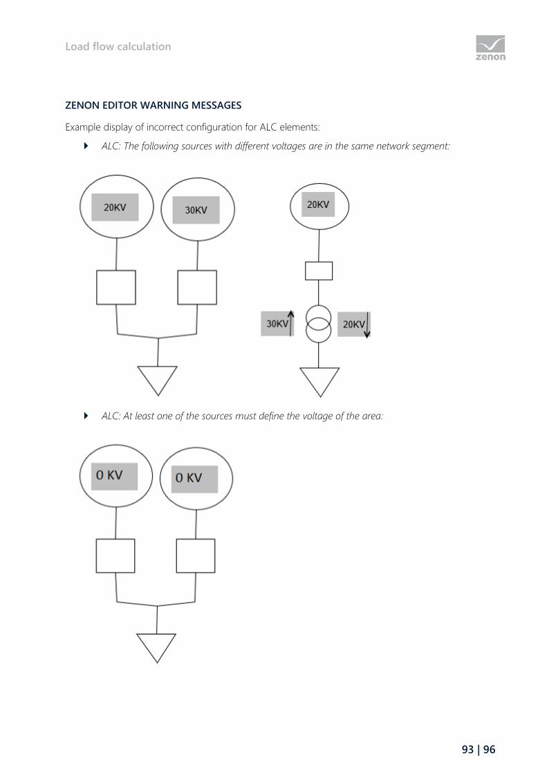
Load flow calculation
93 | 96
ZENON EDITOR WARNING MESSAGES
Example display of incorrect configuration for ALC elements:
ALC: The following sources with different voltages are in the same network segment:
ALC: At least one of the sources must define the voltage of the area:
State Estimator
94 | 96
ALC: Elements without connection to a source:
10 State Estimator
The State Estimator module is an additional module to the Load Flow Calculation module.
If, at the nodes in the topological network, not all power in or out is known for a load flow calculation,
the State Estimator can reconstruct this from several measured values in the network.
Electrical parameters (power outputs) are estimated by the State Estimator. To do this, the State
Estimator measures the values of all measuring points on lines.
The measured values are configured in the properties of the functional ALC elements. These
elements include the combined element as well as all lines. Variables that display the
measured values for the calculation of the state estimator are linked in these properties.
These measured values are the basis for the calculation of the load flow in the topological
network.
The result of the State Estimator is written to the same variables as the result of a load flow
calculation. This result is also used for a topological interlocking check, as well as the (n-1)
calculation.
Starting from a given Jacobian matrix of the Load Flow Calculation module, the voltages and phase
differences of the individual busbars are calculated.
The State Estimator determines approximated values for voltage and phases. These calculated values
are compared to the measured values. The calculation is repeated recursively until the precision
required for the State Estimator has been achieved. This precision is 0.0001.
The state estimator can only detect whether the precision has been achieved if an over-determined
network that is fully observable has been configured. Over-determined means that the state estimator
has received more relevant measured values than the result values (voltage and phase per bus) that it
must calculate. A network is thus observable if each line has meaningful measured values or both
buses - without measured values of this line - are known or can be calculated.

State Estimator
95 | 96
The state estimator starts calculations - like the load-flow calculation- with an assumed phase 0 on
each bus and a known voltage; or the nominal voltage as an estimated value. Because a current does
not provide information on the phase or the direction of the power, the entry of the measured value
of the current is not sufficient for calculation. The effective power or reactive power to lines is needed
for the calculation.
Attention: The circumstances of the measured values of the voltage, current and power factor (cos
phi) being known cannot be used to calculate effective power and reactive power from them: this is
because the direction of the resultant load flow remains unknown, the prefix of the power is not
known.
Only once the power is measured for all sources and drains on a bus are measured can this net
power continue to be used in the calculation. This is the case regardless of active power or reactive
power. The power can thus only be determined at a bus directly if only one line or only the net power
is unknown. Otherwise there is a recursive estimate.
10.1 Engineering in the Editor
Configuration steps for the State Estimator module:
1. Activate the State Estimaotr.
a) Go to the Automatic Line Coloring property group in the project properties.
a) In the Activate load flow calculation property, select the Load flow with State Estimator
entry from the drop-down menu.
2. Set the parameters for ALC screen elements that represent lines in the topological network.
Information
The State Estimator module builds on the configuration for the Load Flow
Calculation (on page 66) module.
The State Estimator needs entry of measured values of the effective power or reactive power to
lines.
Note: Because a current does not provide information on the phase or the direction of the power,
the entry of the measured value of the current is not sufficient for calculation.
Configure the measured value of the power factor (cos phi) if either effective power or reactive
power at the same point are known (i.e. if not both). The state estimator will then calculate the other
power (with the same prefix) and use it for further calculations (no longer the power factor).
Even if the voltage, current and power factor (cos phi) are known for a line, it is not sufficient in
order to calculate the measured values of the effective power and reactive power - the prefix of

State Estimator
96 | 96
the power remains unknown. The voltage and the current are taken into account in further
calculations.