automatic flight control system table of … flight control system table of contents ... the...
TRANSCRIPT

AUTOMATIC FLIGHT CONTROL SYSTEM
Table of Contents
May 06/2005 Flight Crew Operating Manual Volume 2REV 2 CSP 100-6 04-00-01
Introduction ......................................................................................................................... 04-01-01Flight Directors (FD) ............................................................................................................ 04-01-02
Description ................................................................................................................. 04-01-02Components and Operation....................................................................................... 04-01-02Flight Director Command Bars................................................................................... 04-01-02Cross-Pointer Command Bars ................................................................................... 04-01-03Flight Guidance Mode Display Area .......................................................................... 04-01-03
Flight Guidance Panel (FGP) .............................................................................................. 04-01-04Flight Director Synchronization ........................................................................................... 04-01-06Flight Director Lateral Modes .............................................................................................. 04-01-07Flight Director Vertical Modes ............................................................................................. 04-01-13Autopilot .............................................................................................................................. 04-01-21
Components and Operation....................................................................................... 04-01-21Description ................................................................................................................. 04-01-21Autopilot Engagement................................................................................................ 04-01-21Autopilot Servo Motors............................................................................................... 04-01-21Out-Of-Trim Indicators ............................................................................................... 04-21-23Master Disconnect Switch.......................................................................................... 04-01-23Autopilot and Yaw Damper Disconnect Lever............................................................04-01-23Autopilot Disengagement........................................................................................... 04-01-23Autopilot Takeoff Configuration Warning.................................................................... 04-01-23
Yaw Damper........................................................................................................................ 04-01-23Description ................................................................................................................. 04-01-23
Controls and Indications...................................................................................................... 01-01-24Description ................................................................................................................. 01-01-24
PFD Messages.................................................................................................................... 04-01-25EICAS Messages ................................................................................................................04-01-27
REV 2


AUTOMATIC FLIGHT CONTROL SYSTEM
Sep 13/2004 Flight Crew Operating Manual Volume 2REV 1 CSP 100-6 04-01-01
INTRODUCTION
The automatic flight control system (AFCS) provides a means of automatically controlling the aircraft flight path. TheAFCS reduces the flight crew workload by providing steering commands through the flight director or automatically flyingthe aircraft through the autopilot. The main functions of the AFCS are:
- Dual independent flight directors- Two axis (pitch and roll) autopilot- Single axis yaw damper
When manually flying the airplane, dual flight directors provide steering commands to the pilots through flight directorcommand bars displayed on the primary flight displays. For automatic flight control, the flight director steering commandsare coupled to the autopilot.
REV 1

AUTOMATIC FLIGHT CONTROL SYSTEM
Volume 2 Flight Crew Operating Manual May 06/200504-01-02 CSP 100-6 REV 2
FLIGHT DIRECTORS (FD)
DESCRIPTION
The flight directors display flight guidance cues on the attitude indicators, thereby assisting the flight crew in maintaininga specified flight path. The flight guidance cues are displayed in the form of flight director command bars. The crew canchoose to hand fly the aircraft with "raw data" (flight directors not displayed), hand fly the aircraft using the flight directorcommand bars, or couple the autopilot to the flight director.
COMPONENTS AND OPERATION
The flight director (and autopilot and yaw damper) processing is done within two flight guidance computer cards in theintegrated avionics processor system (IAPS). The left and right flight guidance computer cards are identical. During pre-cision approach and go-around modes, each flight director provides guidance to the onside displays. In all other flight di-rector modes, only one flight director provides guidance to both left and right flight displays.
The pilot flying can select the onside flight director using the transfer (XFR) button on the flight guidance panel.
If the active flight director fails, a red boxed FD appears on the primary flight display and a cyan FD1(2) FAIL CAS mes-sage is displayed. Selecting the XFR switch on the FGP deselects the failed flight director and allows the functional flightdirector to become active.
FLIGHT DIRECTOR COMMAND BARS
The flight directors provide visual pitch and roll control guidance by means of single cue inverted V-shaped command bars,or cross-pointer command bars. The selection of the preferred display of command bars is made by pushing the REF buttonto show page 3/3 on the PFD. The flight director command bars provide visual guidance to the pilot regardless of the au-topilot engagement mode.
SINGLE CUE COMMAND BARS
20
10
CF
O1101002_
017
SINGLE CUE
DESIRED ATTITUDE20
10
PITCH DOWN COMMAND PITCH UP COMMAND
ROLL LEFT AND CLIMB
COMMAND
ROLL RIGHT AND DESCEND
COMMAND
V 2

AUTOMATIC FLIGHT CONTROL SYSTEM
May 06/2005 Flight Crew Operating Manual Volume 2REV 2 CSP 100-6 04-01-03
FLIGHT DIRECTORS (FD) (Cont)
CROSS-POINTER COMMAND BARS
FLIGHT GUIDANCE MODE DISPLAY AREA
Lateral and vertical FD modes are presented in the flight mode annunciator display on each PFD. The flight guidance modedisplay area is located above the attitude indicator.
The mode display area is divided into three sections, separated by two gray vertical lines. The left section displays lateralmodes. The center section displays the autopilot, yaw damper, and active flight director status. The right section displaysvertical modes. Active modes are displayed in green on the top line and armed modes are displayed in white on the bottomline.
20
10
CF
O1
101002_0
20
DOUBLE CUE
DESIRED ATTITUDE
PITCH DOWN COMMAND PITCH UP COMMAND
ROLL LEFT AND CLIMB
COMMAND
ROLL RIGHT AND CLIMB
COMMAND
20
10
00
225IAS
M
.54
.50
.42
.38
4
2
1
1
4
ALTS
20
10
20
10
350 16000
350 00
4
3
100
00
00
352 0080
20
2
29.92 IN
.68
.687
9
UTC
° C
11 : 42
SAT -60-5 ° CISA
385
ROLL AP YD PITCH

AUTOMATIC FLIGHT CONTROL SYSTEM
Volume 2 Flight Crew Operating Manual Sep 13/200404-01-04 CSP 100-6 REV 1
FLIGHT GUIDANCE PANEL (FGP)
The FGP is the mode selection panel that selects and controls the flight director, autopilot, and yaw damper functions. TheFGP is located on the glare shield and is accessible to both pilots. The FGP is divided by the functional areas they perform.Those fuctional areas are:
- Flight director/course- Lateral modes- Vertical modes- Autopilot
The flight guidance panel controls are as follows:
FD button — The FD 1 and 2 buttons are used to select and deselect the onside flight director. The flight director is thelateral and vertical steering commands and the text messages representing the selected modes. Push the FD button to selectthe onside flight director. When the flight director is activated using the FD button, the basic modes pitch and roll are au-tomatically selected. With the FD active, push the FD button to deselect the flight director. With the autopilot engaged andthe flight director showing, deselection of the flight director using the FD button removes the steering commands and notthe text messages, however, the flight director continues to supply steering commands to the autopilot.
CRS knob — A course set knob (CRS) is located at each end of the FGP. These knobs individually set the courses on theleft and right PFD HSI displays. The CRS knob primarily set the course for a VOR radial or LOC course. The course knobshave a push button in the center to synchronize the display to the aircraft “direct-to” course.
NAV (navigation) button — Pressing the NAV button alternately selects and deselects the navigation mode. The NAVmode normally intercepts route segments identified with VOR radials and intercepts and flies desired FMS tracks.
HDG button and knob— Pressing the HDG button engages the heading mode and displays a green HDG annunciationon the PFDs. The heading button controls the heading bug and digital display. Pressing the push button in the center of theHDG knob synchronizes the HDG bug on all display units to the aircraft current heading. The flight director command barscommand a turn in the direction the heading bug was moved to achieve the set heading.
APPR (approach) button — The APPR mode is used for all approaches, regardless of NAV source or whether a verticalmode is also associated with the approach. Pressing the APPR button arms both localizer and glideslope modes andis normally used to select lateral and vertical steering for ILS and FMS. The VOR approach mode is selected by pressingthe APPR mode button with the navigation receiver tuned to a VOR frequency and selected as the active nav source. Whenthe navigation receiver is tuned to an ILS frequency, ILS is selected as the active navigation source. Selection of APPRmode when the NAV source is FMS engages the FMS lateral mode the same as described for NAV, and also arms VNAVfor approach.
B/C button — The back course button is used to alternately select and deselect the back course mode for flying a localizerback course approach.
1/2 BANK button — Pressing this button alternately selects or deselects a reduced maximum bank angle of 15° (for alllateral modes, except roll) on both FDs. When selected, a green 1/2 bank arc appears on the top of the attitude directionindicators.
FLC (flight level change) button — Depressing the FLC button engages the flight level change mode, which sycronizeson engagement to the current airspeed/mach. The speed reference can then be changed with the SPEED knob. Pushing theFLC switch again disengages the mode.
SPEEDHDGCRS
DOWN
UP
ALT AP/YD DISC CRS
FD NAV
1/2 BANK
HDG APPR
B/C
FLC VS
VNAV
ALT AP
XFR
YD FD
CF
O040
1002_ 0
01
DIRECT SY NC
C
ANC E
L
PUSH PUSHPUSH PUSH
DIRECT
IA
S /M A C
H
PUSH
S/M A C
H
PUSH
1

AUTOMATIC FLIGHT CONTROL SYSTEM
Sep 13/2004 Flight Crew Operating Manual Volume 2REV 1 CSP 100-6 04-01-05
FLIGHT GUIDANCE PANEL (FGP) (Cont)
SPEED knob — The rotary SPEED knob changes the IAS/Mach speed reference (FLC mode). The speed knob changesthe bug airspeed or Mach at any time. The integral PUSH IAS/MACH button within the SPEED knob toggles the airspeedtape between IAS and Mach. The master flight director computes the airspeed reference, and the slave flight director syn-chronizes to this reference.
VS button — The VS switch selects vertical speed mode. When activated, the system maintains the vertical speed refer-ence. The vertical speed reference is set to the current vertical speed at the time of mode selection. After mode selection,rotation of the DOWN/UP wheel slews the vertical speed reference in the direction of knob rotation. Range is ±8000 fpm.
VNAV (vertical navigation) button — Pressing the VNAV button arms and then captures the FMS pitch steering com-mands of the FDs if FMS is selected as the NAV source, the FMS is programmed for a vertical navigation profile, the alti-tude preselector is set below existing altitude, and the aircraft is within the TOD (top of descent) window or above theexisting altitude for VNAV climb (i.e. VFLC).
ALT (altitude hold) button — Altitude hold may be engaged by depressing the ALT button on the FGP. WhenALT engages, the FD holds the existing altitude at the time the ALT button was pushed except during a precision approachwith the glideslope captured.
ALT (altitude select) knob — A preselected altitude is set via the ALT rotary knob. The altitude preselect mode providesa means for FD/AP to climb or descend to a preselected altitude and then level off and maintain the preselected altitude. Ifan altitude deviation (±200 ft) has occurred, the altitude preselect digits will turn amber and flash, press the PUSH CAN-CEL button in the center of the ALT knob to cancel the flashing. The digits will then revert to cyan.
AP (autopilot) button — Pressing this button engages the autopilot. Pressing a second time disengages the autopilot.
YD (yaw damper) button — Pressing this button engages yaw damper. The YD can be engaged independently ofthe autopilot, but the autopilot system does not engage without the YD.
XFR (transfer) button — Selects the desired flight director (left or right) to command the autopilot.

AUTOMATIC FLIGHT CONTROL SYSTEM
Volume 2 Flight Crew Operating Manual May 06/200504-01-06 CSP 100-6 REV 2
FLIGHT DIRECTOR SYNCHRONIZATION
Flight director synchronization is selected by pushing the AP/FD sync button, located on the side of each control wheel,while in operational mode, which enables FD synchronization selection. FD synchronization selection is enabled while inroll, lateral GA, pitch, vertical TO, altitude hold, vertical speed, flight level change and vertical GA modes.
FD synchronization is deselected when the AP/FD button is released, and no vertical or lateral mode is active that has asynchronization reference, a lateral or vertical mode switch is pressed, or the FD is off.
CF
O11
0100
2_03
0
AUTOPILOT
SYNCHRONIZATION
SWITCH
IDINPH
TX
OFF
RUN
L ENGINE
OFF
RUN
TO
CLB
MAXREV
APR
TO
IDLE
MAX
R ENGINE
REV
TO/GA
CFO
1101
002-
029
TOGA
SWITCH (2)
TAKE-OFF/GO AROUND
(TO/GA) SWITCH
THRUST
REVERSER
LEVER
REV
REV
CLB
IDLE
TO/GA
APR
EV 2

AUTOMATIC FLIGHT CONTROL SYSTEM
May 06/2005 Flight Crew Operating Manual Volume 2REV 2 CSP 100-6 04-01-07
FLIGHT DIRECTOR LATERAL MODES
There are eight lateral FD modes.
- ROLL- TO (takeoff)- HDG (heading)- NAV (navigation, i.e. FMS, VOR)- GA (go-around)- APPR (approach)- BC (back course)- 1/2 BNK (half bank)
Lateral modes are armed or activated by push buttons on the flight guidance panel or the thrust levers. Disabling the activelateral mode is accomplished by re-selecting the active FGP push button or by selecting another lateral mode.
ROLL MODE
Roll mode is the default lateral mode of the flight director. When the autopilot is engaged and no other lateral mode is se-lected, the flight director automatically defaults to the basic ROLL mode. Roll mode generates commands to hold the ex-isting heading when the mode is selected unless the roll angle is over 5°. In that case, commands are generated to hold theroll angle present at the time of mode selection. The roll mode reference is reset to the current heading, or the current rollangle upon autopilot engagement or flight director synchronization.
The FD automatically defaults to the basic ROLL mode when NAV mode is being used and the navigation source is lost.ROLL mode is annunciated by a green ROLL in the active lateral field of the PFD.
CF
O0401002_006
00
225IAS
M
.54
.50
.42
.384200
4
2
1
1
4
ALTS
AP YD PTCH
20
10
20
10
350 16000
350 00
4
3
100
00
00
352 00
80
20
2
29.92 IN
.46
.46.5
1
UTC
° C
11 : 42
SAT -15
-5 ° CISA
ROLL

AUTOMATIC FLIGHT CONTROL SYSTEM
Volume 2 Flight Crew Operating Manual May 06/200504-01-08 CSP 100-6 REV 2
FLIGHT DIRECTOR LATERAL MODES (Cont)
LATERAL TAKEOFF MODE
Pushing one of the TO/GA switches, prior to the start of the takeoff roll, activates the lateral and vertical takeoff modes.However, a takeoff flap setting is required to get proper takeoff mode display.
The lateral takeoff mode generates a heading hold command once airborne. The heading hold is based upon the actual air-craft heading at the moment of weight-off-wheels. The mode has a 5° bank angle authority. Lateral takeoff mode is annun-ciated by a green TO in the active lateral field of the PFD.
HEADING MODE
The HDG switch and knob generate commands to capture and maintain a pilot selected heading. Selected headings are dis-played by a digital heading readout and heading bug on the PFD.
Heading mode is selected by pushing the HDG push button on the FGP. The HDG knob is used to change the selected head-ing command. Pressing the push button in the center of the knob resets the heading bug and digital readout to the currentaircraft heading.
Heading mode is indicated by a green HDG in the active lateral field of the PFD.
CF
O0401002_014
00
225IAS
M
.54
.50
.42
.384200
4
2
1
1
4
ALTS
YD
20
10
20
10
350 16000
350 00
4
3
100
00
00
352 00
80
20
2
29.92 IN
.46
.46.5
1
UTC
° C
11 : 42
SAT -15
-5 ° CISA
TO TO
CF
O0401002_007
00
225IAS
M
.54
.50
.42
.384200
4
2
1
1
4
AP YD PTCH
20
10
20
10
350 16000
350 00
4
3
100
00
00
352 00
80
20
2
29.92 IN
.46
.46.5
1
UTC
° C
11 : 42
SAT -15
-5 ° CISA
HDG

AUTOMATIC FLIGHT CONTROL SYSTEM
May 06/2005 Flight Crew Operating Manual Volume 2REV 2 CSP 100-6 04-01-09
FLIGHT DIRECTOR LATERAL MODES (Cont)
NAV MODE
This mode is activated by pushing the (NAV) switch on the FGP, and it can be deselected in one of the following ways:
- Pushing NAV switch again- Selecting another lateral mode- Changing the frequency of the onside navigation signal- Changing the NAV source- Turning off the flight directors with the AP disengaged- Changing coupled side
Navigation mode generates commands to capture and track the active navigation source, displayed on the PFD. Navigationmode arms when it is selected, but it cannot capture if the FGC is not receiving valid navigation data.
The following are navigation submodes:
- FMS navigation mode- VOR navigation mode- LOC and backcourse mode
Prior to capture, the flight director operates in heading mode. The capture point is a function of closure rate. Navigationcapture clears the heading select mode. A localizer capture also clears the half bank mode.
Dead reckoning operation is executed during the VOR station passage.
When navigation mode is selected, the active lateral mode is annunciated on the PFD by the green HDG (in lateral capturefield) and the armed navigation is annunciated in and a white Nav source identifier (VOR1, VOR2, LOC1, LOC2, FMS1,FMS2 in the lateral arm field). Navigation mode capture/tracking is annunciated on the PFD with a green message in thelateral capture field, which identifies the navigation source (VOR1, VOR2, LOC1, LOC2, FMS1, FMS2). Dead reckoningoperation is annunciated on the PFD by a small green DR letters, added to the lateral nav capture annunciation.
The flight director provides a NAV to NAV capture logic that allows automatic transition from FMS navigation to LOC orback course mode, when FMS is the selected NAV source.
CF
O0401002_011
00
225IAS
M
.54
.50
.42
.384200
4
2
1
1
4
AP YD
20
10
20
10
350 16000
350 00
4
3
100
00
00
352 00
80
20
2
29.92 IN
.46
.46.5
1
UTC
° C
11 : 42
SAT -15
-5 ° CISA
LNV 1 VS
REV 2

AUTOMATIC FLIGHT CONTROL SYSTEM
Volume 2 Flight Crew Operating Manual May 06/200504-01-10 CSP 100-6 REV 2
FLIGHT DIRECTOR LATERAL MODES (Cont)
GO AROUND MODE
When airborne, pressing either TOGA switch activates the lateral and vertical go-around modes. Lateral go-around modegenerates a heading hold command with a five degree bank angle authority. Lateral go-around is annunciated with a greenGA message in the lateral capture field of the PFD.
Pushing the TOGA switch disengages the autopilot. The resultant autopilot warning may be cancelled by another push ofthe TOGA switch or by pushing the MWS switch on the control wheel.
GA is deselected if the following occurs:
- Autopilot engagement.- Another lateral or vertical mode is selected.- Pressing the SYNC button, which selects pitch and roll modes.- Turning off the Flight Directors.- Changing the coupled side.
Selection of GA causes the flight directors to operate independently. Selection of GA mode disengages the autopilot (butnot the Yaw Damper), and clears all other existing modes.
00
225IAS
M
.54
.50
.42
.384200
4
2
1
1
4
AP YD PTCH
20
10
20
10
350 16000
350 00
4
3
100
00
00
352 00
80
20
2
29.92 IN
.46
.46.5
1
UTC
° C
11 : 42
SAT -15
-5 ° CISA
VOR1
00
225IAS
M
.54
.50
.42
.384200
4
2
1
1
4
350 16000
350 00
4
3
100
00
00
352 00
80
20
2
29.92 IN
.46
.46.5
1
UTC
° C
11 : 42
SAT -15
-5 ° CISA
20
10
ALTS
YDGA GA
20
10
EV 2
AUTOMATIC FLIGHT CONTROL SYSTEM
Sep 13/2004 Flight Crew Operating Manual Volume 2REV 1 CSP 100-6 04-01-11
FLIGHT DIRECTOR LATERAL MODES (Cont)
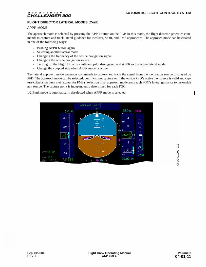
APPR MODE
The approach mode is selected by pressing the APPR button on the FGP. In this mode, the flight director generates com-mands to capture and track lateral guidance for localizer, VOR, and FMS approaches. The approach mode can be clearedin one of the following ways:
- Pushing APPR button again- Selecting another lateral mode- Changing the frequency of the onside navigation signal- Changing the onside navigation source- Turning off the Flight Directors with autopilot disengaged and APPR as the active lateral mode- Change the coupled side when APPR mode is active
The lateral approach mode generates commands to capture and track the signal from the navigation source displayed onPFD. The approach mode can be selected, but it will not capture until the onside PFD’s active nav source is valid and cap-ture criteria has been met (except for FMS). Selection of an approach mode arms each FGC’s lateral guidance to the onsidenav source. The capture point is independently determined for each FGC.
1/2 Bank mode is automatically deselected when APPR mode is selected.
CF
O04
0100
2_01
2
00
225IAS
M
.54
.50
.42
.384200
4
2
1
1
4
APPR VOR1 AP YD
20
10
20
10
350 16000
350 00
4
3
100
00
00
352 0080
20
2
29.92 IN
.46
.46.5
1
UTC
° C
11 : 42
SAT -15-5 ° CISA
1

AUTOMATIC FLIGHT CONTROL SYSTEM
Volume 2 Flight Crew Operating Manual Sep 13/200404-01-12 CSP 100-6 REV 1
FLIGHT DIRECTOR LATERAL MODES (Cont)
B/C MODE
The localizer/back course mode can be selected by pushing the B/C button on the FGP. Back course mode can be deselectedin one of the following ways:
- Pressing the B/C button again- Selecting another lateral mode- Changing the frequency of the navigation signal- Changing the preselect navigation source (other than changing to localizer)
Back course mode generates the command to capture and track the back course signal from the selected LOC source, dis-played on the PFD. Upon back course mode selection, the flight director will arm to capture the signal from the selectednav source. If the flight director is in nav mode capturing/tracking FMS (with the LOC as preselect source) it will continueto track FMS and arm for LOC capture.
Back course capture clears half bank and heading modes. Back course mode is annunciated on the PFD with two messages:green in the lateral capture field indicating captured NAV source and also green in the lateral arm field, which identifiesthe armed NAV source (B/C1 or B/C2).
CF
O04
0100
2_01
3
00
225IAS
M
.54
.50
.42
.384200
4
2
1
1
4
APPR B/C 2 AP YD ALTS
20
10
20
10
350 16000
350 00
4
3
100
00
00
352 0080
20
2
29.92 IN
.46
.46.5
1
UTC
° C
11 : 42
SAT -15-5 ° CISA
1

AUTOMATIC FLIGHT CONTROL SYSTEM
May 06/2005 Flight Crew Operating Manual Volume 2REV 2 CSP 100-6 04-01-13
FLIGHT DIRECTOR LATERAL MODES (Cont)
1/2 BANK MODE
Half bank mode can be manually selected by pushing the 1/2 BANK button on the FGP except when any of the followingmodes is active; Approach Capture or Track, NAV Capture or Track in LOC or GA. It will be automatically selected whenclimbing through 31 600 ft. pressure altitude (the half bank transition altitude) or if the aircraft is above that altitude whenthe flight director is turned on. This mode selection is inhibited when the aircraft is in takeoff mode, go aroundmode, approach mode capture or localizer capture.
The Half Bank Mode is manually cleared by pushing the 1/2 BANK button again. This mode is automatically cleared whendescending through the half bank transition altitude, by takeoff mode, by go-around mode, by approach capture or any lo-calizer capture.
The Half Bank Mode reduces the maximum commanded bank angle to 15°. Half Bank Mode has no effect on roll modeoperation. Half Bank Mode is annunciated by a green arc drawn above the roll scale index marks on the PFD. The lengthof the mark represents +/- 15° of roll.
FLIGHT DIRECTOR VERTICAL MODES
There are 10 vertical flight director modes.
- Pitch (PTCH)- Altitude preselect (ALTS)/Altitude hold (ALT)- Takeoff (TO)- Overspeed- Vertical Navigation (VNAV)- Glidepath (GP)- FLC- Vertical speed (VS)- Glideslope (GS)- Go-around (GA)
Vertical modes are armed or activated by switches or a UP/DOWN wheel on the flight guidance panel or TOGA switcheson the thrust levers. Disabling the active vertical mode is accomplished by pushing the active FGP push button orby selecting another vertical mode.
00
225IAS
M
.54
.50
.42
.384200
4
2
1
1
4
350 16000
350 00
4
3
100
00
00
352 00
80
20
2
29.92 IN
.46
.46.5
1
UTC
° C
11 : 42
SAT -15
-5 ° CISA
10
20
1/2 BNK HDG
ALTV FLC GP
AP YD
APPR LOC2
20
FLC
10
REV 2

AUTOMATIC FLIGHT CONTROL SYSTEM
Volume 2 Flight Crew Operating Manual May 06/200504-01-14 CSP 100-6 REV 2
FLIGHT DIRECTOR VERTICAL MODES (Cont)
PITCH MODE
When pitch mode is selected, the flight director generates commands to hold the current pitch attitude. Selection of the PitchMode is automatic in the following cases:
- Any other vertical mode has been deselected, either manually or automatically- Autopilot is engaged with the FD off- Flight Director is ON with no other vertical mode(s) selected- The SYNC button is pressed in go-around mode- Go-around is active mode and another lateral mode is selected- While the AP is engaged or FD is ON, the coupled side is changed- The pre-select altitude is changed during the pre-select altitude capture- The FGP UP/DOWN wheel is moved (except in: VS Mode, Vertical Glide path, Capture or Track, or Overspeed
function)- If VNAV has been selected, the FMS may select the pitch hold mode- Deselecting VNAV when GP, PATH or FCS ALTS are the active modes with flight plan target altitude as the active
reference
The pitch mode is deselected when selection or automatic capture of another active vertical mode occurs. The pitch refer-ence value can be changed by using the UP/DOWN wheel on the FGP. Rotation of the VS/pitch wheel changes the pitchreference by 0.5°/click. The pitch reference is reset to the current pitch attitude, upon either AP engagement, transferringto pitch mode, or FD sync. When in altitude select capture, rotating the VS/pitch wheel also re-arms altitude select mode.
When capturing or tracking a preselected altitude, a new preselect altitude must be chosen prior to selection of pitch mode,to avoid an immediate recapture of the existing preselected altitude.
Pitch Mode is annunciated by PTCH in green in the vertical capture field.
00
225IAS
M
.54
.50
.42
.384200
4
2
1
1
420
10
350 16000
350 00
4
3
1 00
00
00
352 00
80
20
2
29.92 IN
.46
.46.5
UTC
° C
11 : 42
SAT -15
-5 ° CISA
YD PTCHROLL
1
20
10

AUTOMATIC FLIGHT CONTROL SYSTEM
May 06/2005 Flight Crew Operating Manual Volume 2REV 2 CSP 100-6 04-01-15
FLIGHT DIRECTOR VERTICAL MODES (Cont)
ALTITUDE SELECT (ALTS)
The altitude select mode consists of arm, capture and track states. In the arm state, the FGC monitors aircraft closure ratestowards the target altitude and determines the optimum capture point. The capture state performs calculations for a smoothacquisition of the target altitude. In the track state, the system maintains the target altitude. There are two possible targetaltitudes for ALTS operation:
- Preselect Altitude value – Manually selected by the pilot using the ALT switch on the FGP- FMS flight plan target altitude provided by the FMS
The ALTS mode will capture and track the altitude that is closest in the direction the aircraft is headed. This mode is auto-matically selected (no button for manual selection is provided) upon existence of any mode (FD is selected on, or AP isengaged) except for glideslope capture, vertical go around, altitude hold or VNAV glide path capture, while the FMS alti-tude is invalid or missing.
ALTS arm is deselected upon occurrence of any of the following:
- Automatic transition to the capture state- Turning off the FD while the AP is disengaged- Activation of APPR mode- Selection of vertical go-around or altitude hold modes
ALTS capture is deselected upon the occurrence of any of the following:
- Automatic transition to the track state- Turning off the FD while the AP is disengaged- Selection of any other active vertical mode- Turning the altitude preselect knob- If VNAV is deselected, pitch shall be selected as the active mode
Deselecting of ALTS track will occur due to any of the following:
- Turning off the FD while AP is disengaged- Turning the altitude preselect knob when the VNAV altitude is not the same as preselected altitude being tracked;
Altitude hold will be automatically selected as the active mode- A change of the FMS flight plan target altitude if the VNAV altitude is target; altitude hold is automatically
selected as the active mode- If ALTS is tracking the flight plan target altitude and VNAV is deselected, altitude hold shall be the active mode.- Activation of Vertical APPR Capture/Track states- Selection of any other active vertical mode
Altitude select mode generates commands to capture and track selected altitude displayed on the PFD. During the altitudecapture maneuver, or after being established on the selected altitude (altitude track), if the selected altitude is changed, thealtitude hold mode is automatically selected. A deselection of vertical navigation mode, while capturing/tracking an FMSaltitude, will also select altitude hold mode. In addition to altitude preselect being set with the altitude preselect knob, aFMS flight path target altitude can be programmed for use with VNAV. In the VNAV glide path capture mode, capturingthe preselected altitude is prohibited.

AUTOMATIC FLIGHT CONTROL SYSTEM
Volume 2 Flight Crew Operating Manual May 06/200504-01-16 CSP 100-6 REV 2
FLIGHT DIRECTOR VERTICAL MODES (Cont)
When the closest altitude being approached is the preselected altitude, altitude preselect is annunciated on the PFD in oneof the following ways:
- ALTS in white color in the vertical arm field — arm- ALTS CAP in green color in the vertical capture field — capture- ALTS in green color in the vertical capture field — track
When the closest altitude being approached is the FMS altitude, altitude select is annunciated on the PFD in one of thefollowing ways:
- ALTV in white color in the vertical arm field — arm- ALTV CAP in green color in the vertical capture field — capture- ALTV in green color in the vertical capture field — track
00
225IAS
M
.54
.50
.42
.384200
4
2
1
1
4
350 16000
350 00
4
3
100
00
00
2
29.92 IN
.46
UTC
° C
11 : 42
SAT -15
-5 ° CISA
20
10
AP YD VSALTS 2000
.461
.5
00
80
20
352
20
10
AUTOMATIC FLIGHT CONTROL SYSTEM
Sep 13/2004 Flight Crew Operating Manual Volume 2REV 1 CSP 100-6 04-01-17
FLIGHT DIRECTOR VERTICAL MODES (Cont)
ALTITUDE ALERT SYSTEM
The altitude alert system provides aural and visual indications of the preselected altitude capture and tracking. It also pro-vides audio and visual indications of altitude deviation from the preselected altitude.
The altitude alerting system processes data from the ADCs and is independent of the flight director or autopilot modes.
At approximately 1000 feet prior to the preselected altitude, an aural tone and flashing altitude preselect digits advises thepilot of impending level off. If the flight director is tracking a preselected altitude and the aircraft subsequently deviatesmore than 200 feet from the selected altitude, the altitude bugs flashes and a series of tones are produced.
If the aircraft continues to deviate uncorrected, at ± 1000 ft. from the selected altitude, the altitude bugs and digital readoutflash amber and audible tones are produced.
(ALT) MODE
Selection of Altitude Hold Mode occurs due to one of the following:
- Pressing the ALT button on the FGP, except that ALT HOLD is inhibited when in glideslope capture- If VNAV has been selected, the FMS may select the altitude hold mode- Altitude PreSelect is changed during ALTS track state- While in ALTS track, a change of the FMS VNAV altitude if the VNAV altitude is the target. Altitude Hold is auto-
matically selected as the active mode
Altitude Hold Mode can be deselected, as follows:
- Turning Off the Flight Directors, while the AP is disengaged- Another active vertical mode is selected- If VNAV has been selected, the FMS may select another active vertical mode- Another vertical mode is automatically captured, becoming the active mode- The ALT mode button on FGP is pressed- Changing coupled side
This mode is annunciated by a green ALT in the vertical capture field.
TAKEOFF MODE
Prior to takeoff, the vertical takeoff mode is selected when either TOGA switch is pressed and the flaps are set to a takeoffsetting. A green TO message is displayed in the active vertical field. This mode generates a pitch up command that is cal-culated when the pilot enters V2 and VR values in the REFS 1/3 page or via the FMS TAKEOFF REF page. Loss of anengine reduces the pitch up command appropriately. If V2 and VR are not entered when the TOGA switch is pushed, thecommand bars are removed from the display.
GO-AROUND MODE (GA)
Go-around (GA) mode is selected by pushing one of throttle-mounted TOGA buttons while airborne. Selection of GAmode turns on both flight directors, disengages the autopilot (but not the yaw damper), clears all other vertical modes (ex-cept overspeed), and switches the flight guidance commands to a dual-independent configuration.
This mode is cleared by:
- Turning off the flight directors- Engaging the autopilot- Selecting another vertical mode- Pressing AP/FD SYNC button- Rotating the UP/DOWN wheel, which selects Pitch Hold
The GA Mode generates a 10° pitch up command.
This mode is annunciated by a green GA in the lateral and vertical capture field.
REV 1

AUTOMATIC FLIGHT CONTROL SYSTEM
Volume 2 Flight Crew Operating Manual May 06/200504-01-18 CSP 100-6 REV 2
FLIGHT DIRECTOR VERTICAL MODES (Cont)
FLIGHT LEVEL CHANGE (FLC) MODE
In flight level change mode (FLC), the flight director provides commands to acquire and track an IAS or Mach referenceairspeed. The IAS/MACH reference values may be adjusted by turning the speed knob on the FGP.
The IAS/MACH reference values, may be adjusted by the pilot by turning the Speed knob on FGP. These values can alsobe synchronized by the FGC or by the FMS when in VNAV mode and RESUME VNAV PLAN SPEED is selected on theFMS PERF MENU page.
FLC mode may be selected in the following ways:
- Pressing the FLC button on the FGP, except FLC is inhibited from being selected while in the Vertical ApproachCapture / Track Mode
- Using FMS, if VNAV has been selected
FLC mode may be deselected as follows:
- Turning the FD off while the AP is disengaged- Another vertical mode is selected or automatically captured- If VNAV has been selected, and FMS selects another active vertical mode- Pressing FLC button on the FGP- Changing the coupled side
When the FLC mode is first selected, the flight director synchronizes the IAS or Mach airspeed reference to the currentspeed.
FLC is displayed in green letters in the vertical capture field.
OVERSPEED MODE
If any significant overspeed occurs when the aircraft is at or above the overspeed transition altitude and airspeed is greaterthan 0.845 MI, or is below the overspeed transition altitude and airspeed is greater than 10 kt above VMO. Overspeed Modeis automatically engaged by the FGC unless altitude hold or altitude preselect are active. The FGC generates the commandsto reduce the airspeed to below VMO/ MMO. While in overspeed mode, the selection or activation of a vertical mode otherthan altitude hold or ALTS capture or track is inhibited. Activation of overspeed mode causes the FGC to automaticallyturn on the flight directors and inhibit the FD from being turned off until another mode is manually or automatically select-ed.
Flight Guidance can not be deselected in FLC Overspeed. While in FLC Overspeed, the Altitude Preselector will not inhibitcommands to climb or descend as required to capture the reference airspeed.
When Flight Level Change Overspeed is detected, a FLC OSPD flashing in amber in the top (capture) field on the PFD. IfVNAV is active in the vertical field, a VFLC OSPD flashing amber CAS is depicted on the PFD.
VERTICAL NAVIGATION MODE
VNAV mode allows the FMS to execute its vertical flight plan by issuing various commands to the FCS. Therefore, VNAVis not a FCS mode, but enables the FMS to command various FCS vertical modes and to provide references associated withthose modes. VNAV is selected only when onside FMS is the active NAV source on the PFD. VNAV mode is selected bypressing the VNAV button on FGP. VNAV is inhibited when the FCS is in the vertical approach capture/track, if ILS is thevertical source, or when Overspeed mode is active.
VNAV mode is deselected as follows:
- Turning off the FD while the AP is disengaged- Automatic capture/track of vertical approach mode, when ILS is the vertical source- Selecting TO or GA mode- Changing the source of the active VNAV data- By pressing the VNAV mode button on the FGP
EV 2

AUTOMATIC FLIGHT CONTROL SYSTEM
May 06/2005 Flight Crew Operating Manual Volume 2REV 2 CSP 100-6 04-01-19
FLIGHT DIRECTOR VERTICAL MODES (Cont)
VERTICAL SPEED MODE (VS)
When the VS mode is selected, the Flight Guidance Computer (FGC) commands the aircraft to climb or descend with avertical speed measured in feet per minute. Initially the rate will be vertical speed sensed at the time of VS mode engage-ment.
Turning the UP/DOWN wheel on the FGP changes the VS reference value. Each click of the wheel is equal to ± 100 ft/min.
APPROACH MODE (APPR)
In the approach mode, the FGC generates commands to track vertical guidance for ILS precision glideslope approaches orfor FMS non-precision glide path (GP) approaches. Approach mode is selected by pushing the APPR button on the FGP.
GLIDESLOPE MODE
Glideslope is automatically selected when in approach mode, inbound, with a valid localizer as the lateral navigationsource. Glideslope mode is cleared by deselection of approach mode. When armed, glideslope mode is also cleared by turn-ing outbound, or by loss of a valid localizer as the lateral navigation source. When captured, glideslope mode is cleared bychanging the source of the lateral navigation source to anything other than a valid localizer.
Glideslope mode generates commands to capture and track glideslope. Captures can be performed from below or above thebeam. The capture point is a function of the closure rate, with the capture point moving away from the beam for high closurerates. Capture will not occur if the localizer is not captured, or if the FGC is not receiving valid glideslope data.
Upon glideslope capture, other vertical modes are automatically cleared.
When the APPR capture occurs, the flight directors automatically change to independent mode. When the glideslope cap-tures are not concurrent and only one side has captured, vertical mode selection, PFD annunciation, etc. operate indepen-dently on the noncaptured side.
The GS mode is deselected when one of the following occur:
- Another mode is selected.- Changing the active NAV source.- VOR/LOC frequency is changed.- By pressing APPR button again. - Changing the XFR side when APPR is armed.- The FDs are turned off while the AP disengages.
Glideslope arm is annunciated by the white GS message in the vertical (arm) field on the PFD.
CF
O0401002_009
00
225IAS
M
.54
.50
.42
.384200
4
2
1
1
4
AP YD VS
20
10
20
10
350 16000
350 00
4
3
100
00
00
352 00
80
20
2
29.92 IN
.46
.46.5
1
UTC
° C
11 : 42
SAT -15
-5 ° CISA
ROLL 2000

AUTOMATIC FLIGHT CONTROL SYSTEM
Volume 2 Flight Crew Operating Manual May 06/200504-01-20 CSP 100-6 REV 2
FLIGHT DIRECTOR VERTICAL MODES (Cont)
GLIDEPATH MODE
This mode can be selected only by the FMS, as follows:
- While FCS is in the VNAV mode and approach mode- FMS is the active Nav source- No preselect Nav source is active- FMS VNAV is valid
There is no button for glide path mode on the FGP. Glide path is automatically deselected/cleared by deselection of VNAVor approach modes or by selection or capture of another active vertical mode.
Glide path mode generates commands to track a vertical path, defined by the FMS.
Glide path capture disables use of the preselected altitude mode operation. Glide path arm is annunciated with a white GPin the vertical arm field of the PFD. Glide path capture is annunciated by the green GP in the vertical capture field on thePFD.
CF
O0401002_021
00
225IAS
M
.54
.50
.42
.384200
4
2
1
1
4
APPR LOC1 AP YD GS
20
10
20
10
350 16000
350 00
4
3
100
00
00
352 00
80
20
2
29.92 IN
.46
.46.5
1
UTC
° C
11 : 42
SAT -15
-5 ° CISA
CF
O0401002_010
00
225IAS
M
.54
.50
.42
.384200
4
2
1
1
4
ALTV FLC GPAPPR LOC2
AP YD PTCH
20
10
20
10
350 16000
350 00
4
3
100
00
00
352 00
80
20
2
29.92 IN
.46
.46.5
1
UTC
° C
11 : 42
SAT -15
-5 ° CISA
HDG

AUTOMATIC FLIGHT CONTROL SYSTEM
May 06/2005 Flight Crew Operating Manual Volume 2REV 2 CSP 100-6 04-01-21
AUTOPILOT
DESCRIPTION
The Challenger 300 his equipped with a three axis digital fail-passive autopilot. Autopilot servos provide command inputsto the ailerons and elevators. The rudder is controlled by the yaw damper system. The coupled flight guidance computerprovides the flight guidance signals to drive the servos. Both flight guidance computers must be operational for the auto-pilot to function.
Upon occurrence of any single failure, the autopilot will not:
- Cause significant displacement of the aircraft from its approach path or altitude loss below the nominal glide path- (Upon system disconnection) Involve any out-of-trim condition not easily controlled by the pilot- Cause any action to occur with the flight control system that is not readily apparent to the pilot, either by control
column movement or advisory display
The automatic flight-control system (AFCS) consists of dual-independent flight directors, a three axis autopilot, and auto-matic pitch trim and yaw damper system.
The AFCS operates with the integrated-avionics processor system (IAPS). The IAPS collects the data for the avionics sys-tems. The AFCS gives the course, heading, and preselected altitude data to the electronic flight instrument system (EFIS).
The AFCS calculates the vertical and lateral flight-guidance commands to keep the aircraft on the correct pitch/roll attitude.The flight directors show the flight-guidance commands on the primary flight displays.
ENGAGEMENT PARAMETERS
The autopilot can be engaged using the AP switch on the FGP, if the following conditions exist:
- Yaw damper is operable- Both flight guidance computers (FGCs) are serviceable- At least one channel of the horizontal stabilizer trim is engaged and the FCCs detect no faults with the horizontal
stabilizer trim system- No significant instability of the aircraft exists
COMPONENTS AND OPERATION
AUTOPILOT ENGAGEMENT
The autopilot is engaged by pressing the AP switch located on the flight guidance panel. When the autopilot is engaged,both channels of the autopilot are coupled to the onside flight guidance computer. Autopilot engagement is indicated on thePFD by a green AP indication.
Pressing the AP switch on the FGP when the autopilot is engaged will cause the autopilot to disengage.
AUTOPILOT SERVO MOTORS
When the autopilot is engaged, the controlling FGC directs pitch and roll commands to the aileron and elevator servos.When a change in roll or pitch attitude is required, the FGC signals the aileron servo or elevator servo to bias the controlcables to move the associated control surface.
The aileron servo is located on the control cable run for the right aileron. Since the left and right ailerons are normally in-terconnected, the servo is capable of moving both ailerons. The elevator servo is located in the left elevator cable run. Theservo moves both elevators when the elevators are interconnected.
When an out-of-trim condition is sensed in the pitch axis, the FGC signals the horizontal stabilizer trim control unit to re-position the horizontal stabilizer.

AUTOMATIC FLIGHT CONTROL SYSTEM
Volume 2 Flight Crew Operating Manual May 06/200504-01-22 CSP 100-6 REV 2
AUTOPILOT (Cont)
20
DU
AL R
VD
T (
A)
(B)
DU
AL R
VD
T (
A)
(B)
DU
AL R
VD
T (
A)
(B)
SIN
GLE
RV
DT
SIN
GLE
RV
DT
LV
DT
(A
NA
LO
G)
LV
DT
(A
NA
LO
G)
LV
DT
(A
NA
LO
G)
LV
DT
(A
NA
LO
G)
RD
C
CH
AC
H B
FC
U-2
FLA
PS
OV
ER
RID
E
(FR
OM
FC
U)
28V
DC
TR
IM S
ELE
CT
SW
ITC
H
RE
LA
Y
PIL
OT
MA
NU
AL
TR
IM S
WIT
CH
CO
PIL
OT
MA
NU
AL
TR
IM S
WIT
CH
PIL
OT
MA
ST
ER
DIS
CO
NN
EC
T
CO
PIL
OT
MA
ST
ER
DIS
CO
NN
EC
T
PR
I/O
FF
/SE
C
SW
ITC
H
MC
U
CH
1
MC
U
CH
2
RE
LA
Y
HS
TE
CU
(CO
MM
AN
D)
HS
TE
CU
(MO
NIT
OR
)S
EC
ON
DA
RY
R A
HC
R A
DC
R D
CP
SV
OB
-DC
U-1
(HS
)
R-M
FD
-1(H
S)
R-P
FD
-1(H
S)
R-I
OC
-1(H
S)
R-G
PB
US
-5 (
HS
)
R A
FD
B-R
DC
-5
B-R
DC
-1/2
A-R
DC
-5
A-R
DC
-1/2
DC
U
CH A CH B
L A
FD
R IO
CR
FG
C
YD
SV
O
SV
O
L IO
CL F
GC
L A
HC
L A
DC
FG
P
CH A
SP
C
PIL
OT
'S P
ITC
H
DIS
CO
NN
EC
T
(HA
ND
LE
ON
TH
RO
TT
LE
)
TH
RO
TT
LE
QU
AD
/
CO
NT
RO
L
WH
EE
L
PIL
OT
'S R
OLL
DIS
CO
NN
EC
T
(HA
ND
LE
ON
CO
NT
RO
L W
HE
EL)
FC
UF
CU
-2T
O R
DC
CH B
SP
C
L D
CP
L E
LE
VA
TO
R
SU
RF
AC
E P
OS
L A
ILE
RO
N
SU
RF
AC
E P
OS
RU
DD
ER
SU
RF
AC
E P
OS
R A
ILE
RO
N
SU
RF
AC
E P
OS
R E
LE
VA
TO
R
SU
RF
AC
E P
OS
PIL
OT
CO
NT
RO
L
WH
EE
L F
OR
CE
PIL
OT
RU
DD
ER
PE
DA
L F
OR
CE
CO
PIL
OT
RU
DD
ER
PE
DA
L F
OR
CE
CO
PIL
OT
CO
NT
RO
L
WH
EE
L F
OR
CE
A-D
CU
-1(H
S)
L-P
FD
-1(H
S)
L-I
OC
-1(H
S)
L-M
FD
-1(H
S)
PR
IMA
RY
PIT
CH
PR
IMA
RY
RO
LL
PR
IMA
RY
YA
W
PR
IMA
RY
PIT
CH
PR
IMA
RY
RO
LL
PR
IMA
RY
YA
W
L-G
PB
US
-5 (
HS
)
HS
TE
CU
-1 (
HS
)
ND
RM
TR
IM A
VA
ILA
BLE
AP
TR
IM E
NA
BLE
L-A
DC
-1L-A
HC
-1 (
HS
)
L-A
DC
-6
L-G
PB
US
-5 (
HS
)
L-A
HC
-4
A-S
PC
-2
A-S
PC
-1
L-I
OC
-3
L-F
GC
-3
R-A
HC
-4
R-A
DC
-6H
ST
EC
U-2
(H
S)
R-G
PB
US
-5 (
HS
)
ST
AB
1 P
OS
ITIO
N
ST
AB
2 P
OS
ITIO
N
R-G
PB
US
-5 (
HS
)
B-S
PC
-2
ST
ALL W
AR
N D
ISC
ON
NE
CT
B-S
PC
-1
FG
P-2
(R
S-4
22)
R-F
GC
-2 (
RS
-42
2)
ST
ALL W
AR
N
DIS
CO
N
AP
DIS
C S
W A
TO
/GA
SW
A
AP
/FD
SY
NC
SW
A
AP
DIS
C S
W B
TO
/GA
SW
B
AP
/FD
SY
NC
SW
B
A-S
PC
-2
A-S
PC
-1
L-A
DC
-6F
CU
-1
FG
P-1
(R
S-4
22)
L-F
GC
-2 (
RS
-422
)
R-I
OC
-3
R-F
CC
-1
TO
DC
U
TO
DC
U
ICC
AP TRIM ENABLE
NORM TRIM AVAILABLE
R-ADC-1
R-AHC-1 (HS)
12
12

AUTOMATIC FLIGHT CONTROL SYSTEM
May 06/2005 Flight Crew Operating Manual Volume 2REV 2 CSP 100-6 04-01-23
AUTOPILOT (Cont)
OUT-OF-TRIM INDICATIONS
The FGC continuously monitors all three axes of the autopilot when it is engaged. If a control surface is detected to besignificantly out of trim, a CAS caution message is displayed. The amber CAS message identifies whether it is the aileronor elevator that is affected and in which direction the control surface is out of trim.
MASTER DISCONNECT SWITCH
The master disconnect switches are installed on the outboard horn of each control wheel. When the switches are pressedwith the autopilot engaged, the PFD red flashing AP indication appears and the autopilot audio warning sounds for approx-imately 1 1/2 seconds.
If a system fault causes the autopilot to disengage, pressing either master disconnect switches will cancel the red flashingAP message and silence the aural warning.
AUTOPILOT AND YAW DAMPER DISCONNECT LEVER
Pressing the AP/YD DISC lever down disengages the autopilot and yaw damper simultaneously. With the autopilot en-gaged and the disconnect switch pressed down, a flashing red AP message appears on the PFD and the autopilot audiowarning sounds for approximately 1 1/2 seconds.
A red line is visible on the top edge of the switch when the switch has been moved to the disengage position.
AUTOPILOT DISENGAGEMENT
When the autopilot is manually disengaged, the AP symbols on each PFD flash red and an aural warning soundsfor approximately 1 1/2 seconds.
The autopilot can be manually disengaged by:
- Pressing either master disconnect push button on the control wheels- Activating the stab trim switches on the control wheels- Pressing the AP push button on the FGP- Selecting the AP/YD DISC on the FGP- Pressing either TOGA switch- Pressing the YD push button
If a system fault causes the autopilot to automatically disengage, the pilot must press the control wheel master disconnectswitch to cancel the red flashing AP message and silence the aural warning. If the autopilot warning sounds because theTOGA switch is selected, a second press of the TOGA switch clears the warnings.
The autopilot automatically disengages upon stall warning.
AUTOPILOT TAKEOFF CONFIGURATION WARNING
If a takeoff is attempted with the autopilot on, the takeoff configuration warning system presents an EICAS warning mes-sage and sounds an voice alert. The warning sounds when the thrust lever is advanced for takeoff.
YAW DAMPER
DESCRIPTION
The yaw damper provides automatic turn coordination and yaw oscillation damping. The yaw damper actuator is a mechan-ically limited linear actuator.
Yaw damping improves the aircraft’s stability by damping out oscillations in yaw. These oscillations, if not corrected leadsto the phenomenon called dutch roll.
The turn coordination function helps the aircraft into and out of turns. The flight guidance computers (FGCs) provide sig-nals to operate the yaw damper actuators.
The AP/YD DISC switch, YD switch and control wheel disconnect switches will disengage the yaw damper. When a yawdamper channel fails or disconnects, the amber YAW DAMPER FAIL CAS message is displayed.

AUTOMATIC FLIGHT CONTROL SYSTEM
Volume 2 Flight Crew Operating Manual Feb 22/200604-01-24 CSP 100-6 REV 5
CONTROLS AND INDICATIONS
DESCRIPTION
The flight guidance panel (FGP) is the mode selection panel that selects and controls the flight director and autopilot func-tions.
The PFD presents the FGP modes to the pilot through the use of flight mode annunciations and command bars. Autopilotengagement and system malfunctions are presented on the PFD.
An autopilot synchronization switch on the control wheel allows the FD command bars to be synchronized with the actualaircraft vertical and lateral reference when the autopilot is engaged. The AP/YD DISC switch disconnects the autopilot.TOGA switches are provided on both thrust levers.
Normal and non-normal AFCS indications are displayed on the PFDs and MFDs.
SPEEDHDGCRS
DOWN
UP
ALT AP/YD DISC CRS
FD NAV
1/2 BANK
HDG APPR
B/C
FLC VS
VNAV
ALT AP
XFR
YD FD
CF
O0401002_ 0
01
DIRECT SY NC
C
ANC E
L
PUSH PUSHPUSH PUSH
DIRECT
IA
S /M A C
H
PUSH
S/M A C
H
PUSH
CF
O0101002_009
MASTER
DISCONNECT
SWITCH
TRIM SWITCH
DOUBLE ACTING
PITCH/ROLL AND
TRIM ARMING
AUTOPILOT
SYNCHRONIZATION
SWITCH
CHECKLIST LINE
ADVANCE SWITCH
ID
TRANSPONDER
ID SWITCH
(LOCATED BEHIND)
INPH
TX
MICROPHONE
SWITCH
(LOCATED
BEHIND)
ALTS
20
10
20
10
ROLL AP YD PITCH
EV 5

AUTOMATIC FLIGHT CONTROL SYSTEM
Sep 14/2005 Flight Crew Operating Manual Volume 2REV 4 CSP 100-6 04-01-25
PFD MESSAGES
The following indications are presented on the PFD. A brief explanation of each indication is provided.
1. ALT Green Altitude HOLD mode — capturing/tracking
2. ALTS White Altitude select mode — armed preselect
Green Altitude select mode — track, preselect
Flashing Yellow
Altitude select mode — aborted capture preselector
3. ALTS CAP Green Altitude select mode — armed for FMS
4. ALTV White Altitude select mode tracking FMS
Green Altitude select mode — track, preselect
Flashing Yellow
Altitude select mode — aborted capture FMS
5. ALTV CAP Green Altitude select mode — capturing FMS
6. Green AP engaged and not transferred — left FD selected
APFlashing
RedAP disengage warning, and not transferred — Left FD
selected
YellowAP engaged and not transferred, with AP synchronization
in process (the aileron and elevator clutches are released)
7. Green AP engaged and transferred — Right FD selected
APFlashing
RedAP disengage warning, and transferred to the Right FD
YellowAP engaged and transferred, with AP synchronization in process (the aileron and elevator clutches are released)
8.ATT (boxed) Red
The red, boxed, ATT attitude flag shows when attitude data from the selected AHRS are missing or invalid
YellowEach PFD compares the attitude data from the on-side
Attitude Heading Computer (AHC). The ATT flag is yellow when both pitch and roll data are out of limits
9.B/C1B/C2
WhiteBack course mode armed (annunciated in the lateral arm
field, by identifying the nav source)
GreenBack course mode — capture/tracking (annunciated in
the lateral arm field, by identifying the nav source)
10. DR White Dead Reckoning operation
11. FD (boxed) Red Flight director flag (within the attitude ball)
12.FD1 Green
FD computations performed by FD1 (on the copilot’s PFD)
13. FD2 Green FD computations performed by FD2 (on the pilot’s PFD)
14. FLC Green Flight level change mode (on the vertical capture field)
15. GA Green Lateral Go-Around Mode (in lateral capture field)
Green Vertical Go-Around Mode (in vertical capture field)EV 4

AUTOMATIC FLIGHT CONTROL SYSTEM
Volume 2 Flight Crew Operating Manual Sep 14/200504-01-26 CSP 100-6 REV 4
PFD MESSAGES (Cont)
16. LNV1LNV2LOC1LOC2VOR1VOR2
WhiteNavigation or approach mode — armed (annunciator in
the lateral arm field, by identifying nav source)
GreenNavigation or approach mode — capture/tracking (in the
later capture field by identifying the nav source)
17. GS WhiteGlideslope mode — armed (announced in the vertical
arm field)
GreenGlideslope mode — captured (in the vertical capture
field)
18. GP White Glidepath mode — armed in the vertical arm field
Green Glidepath mode — capturing/tracking a vertical path
19. HDG Green Heading select mode
20. PATH Green Vertical Nav mode — capturing/tracking a vertical path
21. PTCH Green Pitch mode
22. ROLL Green Roll mode
23. SYNC Yellow FD synchronization in process
24. TEST Yellow Diagnostic Mode (displayed in large text)
25. TO Green Lateral takeoff mode (annunciator in lateral capture field)
GreenVertical takeoff mode (annunciator in vertical capture
field)
26.V Green
VNAV mode, FMS NAV is valid and not overspeed mode (V is prefixed on the vertical capture annunciator)
Flashing Yellow
VNAV mode, FMS NAV is valid and overspeed mode (V is prefixed on the vertical capture annunciator)
27.VNV Yellow
Vertical Nav mode, and FMS NAV is valid and overspeed mode (V is prefixed on the vertical capture annunciator)
28. VS Green Vertical Speed mod
29. 1/2 BNK Green Half Bank mode
30.v-bars Magenta
Integrated lateral and vertical flight guidance commands (not present if either command is invalid)
31. Pitch command cross-pointer
MagentaVertical flight guidance command (not present if the com-
mand is invalid)
32. Roll command cross-pointer
MagentaLateral flight guidance command (not present if the com-
mand is invalid)
33. Cross-line over the annuncia-tion symbol(s)
RedA required data source is invalid, for the active lateral outer loop (the line is drawn through the active lateral
mode annunciation)
A required data source is invalid, for the active vertical outer loop (the line is drawn through the active vertical
mode annunciation)

AUTOMATIC FLIGHT CONTROL SYSTEM
May 06/2005 Flight Crew Operating Manual Volume 2REV 2 CSP 100-6 04-01-27
EICAS MESSAGES
The autoflight control system messages are shown on the EICAS. In the table below, the AFCS messages, inhibits and auralwarnings are listed. A brief explanation of each message is provided.
MESSAGE INHIBITS MEANINGAURAL
WARNING
CONFIG AILERON TRIM
CONFIG AUTOPILOTCONFIG FLAPS
CONFIG RUDDER TRIM
CONFIG SPOILERSCONFIG STAB TRIM
TO
The aircraft is on the ground and the takeoff parameters (autopilot, flaps, spoilers, and trims in any axis) are not properly config-ured for takeoff. Illumination of the respec-tive red CAS will be accompanied by the takeoff “CONFIGURATION“ voice warning
YES
AFCS MESSAGES FAIL
Monitoring and indication of the autopilot modes may be unreliable
AP HOLDING LWDAP HOLDING RWDAP HOLDING NOSE
DOWNAP HOLDING NOSE
UP
TOThe autopilot is holding control force in the direction indicated
AP STAB TRIM FAIL TOThe autopilot is unable to make a trim cor-rection to the horizontal stabilizer
FD MODE CHANGE
An indirect mode change has occurred within the flight director. An example of an indirect mode change would be NAV or APPR mode changing to ROLL with a navi-gation source or frequency change
YAW DAMPER FAIL TO/LAND The yaw damper has failed
FD 1 FAILFD 2 FAIL
TO/LANDThe respective flight director has failed accompanied by an FD flag on the PFD

AUTOMATIC FLIGHT CONTROL SYSTEM
Volume 2 Flight Crew Operating Manual Sep 13/200404-01-28 CSP 100-6 REV 1
EICAS MESSAGES
The autoflight control system messages are shown on the EICAS. In the table below, the AFCS messages, inhibits and auralwarnings are listed. A brief explanation of each message is provided.
MESSAGE INHIBITS MEANINGAURAL
WARNING
CONFIG AILERON TRIM
CONFIG AUTOPILOTCONFIG FLAPS
CONFIG RUDDER TRIM
CONFIG SPOILERSCONFIG STAB TRIM
TO
The aircraft is on the ground and the takeoff parameters (autopilot, flaps, spoilers, and trims in any axis) are not properly config-ured for takeoff. Illumination of the respec-tive red CAS will be accompanied by the takeoff “CONFIGURATION“ voice warning
YES
AFCS MESSAGES FAIL
Monitoring and indication of the autopilot modes may be unreliable
AP HOLDING LWDAP HOLDING RWDAP HOLDING NOSE
DOWNAP HOLDING NOSE
UP
TOThe autopilot is holding control force in the direction indicated
AP STAB TRIM FAIL TOThe autopilot is unable to make a trim cor-rection to the horizontal stabilizer
FD MODE CHANGE
An indirect mode change has occurred within the flight director. An example of an indirect mode change would be NAV or APPR mode changing to ROLL with a navi-gation source or frequency change
YAW DAMPER FAIL TO/LAND The yaw damper has failed
FD 1 FAILFD 2 FAIL
TO/LANDThe respective flight director has failed accompanied by an FD flag on the PFD