automatic control unit configurator - doc...
TRANSCRIPT
Automatic Control Unit Configurator
User Manual
®
Part. LE09380AA-06/16-01 GF

Automatic Control Unit Configurator
2
®
EN ENGLISH 3

Automatic Control Unit Configurator
3
Use
r man
ual
Contents
1 Hardware and Software requirements 41.1 PC Requirements 4
2. Installation 5
3. Basic operating concepts 83.1 Menus and toolbar 8
3.1.1 Channel 9
3.1.2 Device 10
3.1.3 Monitoring 11
3.1.4 Parameters 11
3.1.5 Commands 13
3.1.6 Events 14
3.1.7 Alarms 14
3.1.8 Utility 15
3.2 Quick access 15
4. Password management 16
5. WiFi dongle 16 5.1 Description 16
5.2 IP Address 16
5.3 Module overview 17
5.3.1 Charging the battery 17
5.3.2 Power on 17
5.3.3 Power off 17
5.3.4 LED Indications 17
5.3.5 Mechanical dimensions [mm] 18
5.4 Dongle menu 18
5.4.1 Command description 18
5.5 Technical data 18

4
®
1. Hardware and Software requirements
1.1 PC RequirementsHARDWARE REQUIREMENTS • Dual core CPU, 2GHz;• 2GB RAM;• hard disk 1GB;• communication port number and type according to the application: USB, WiFi lan, serial port.
SOFTWARE REQUIREMENTS• MS Windows 7, Windows 8.1• Microsoft.NET 4.5.2 or greater
Automatic Control Unit Configurator
5
Use
r man
ual
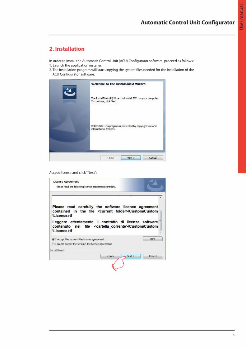
In order to install the Automatic Control Unit (ACU) Configurator software, proceed as follows:1. Launch the application installer;2. The installation program will start copying the system files needed for the installation of the ACU Configurator software.
Accept license and click “Next”:
2. Installation

6
®
2. Installation
The system will prompt to enter the destination folder where ACU Configurator will be installed.The installation procedure will suggest the folder:C:\Program Files\LegrandGroup\ACU_Configurator\ If desired, the user can select another hard drive location:
Click “OK” to continue.
Click “Install” to start installing the software:

Automatic Control Unit Configurator
7
Use
r man
ual
Once the installation has been completed, the following screen is displayed. Click “Finish” to exit installation.

8
®
At startup, the software will show a screen split into 3 areas:
1. Menus and toolbar: it includes the bars used for accessing all the ACU Configurator functions2. Device status: it displays the status of connected device (online, offline, error).3. Quick access pushbuttons: to have a quick way to reach the particular function
3.1 Menus and toolbar
• Home To go to ACU Configurator home page
• Channel - New: to create a new communication channel - View: to view the list of communication channels saved
• Device - New: to create a new device to communicate with - View: to view the list of devices saved
• Monitoring When device is connected, it is possible to view main measures collected by it. Only one device per time could be
connected to PC
• Parameters To setup (online or offline modes) parameters of electronic device. When device is connected, its parameters could be
uploaded into ACU Configurator.
• Commands To send commands to device.
• Events If the connected device supports the event memory, it is possible to download a copy of that and proceed saving it to
Excel or text file.
• Alarms To see alarms collected by connected device
• Log Function not available with this release
3. Basic operating concepts

Automatic Control Unit Configurator
9
Use
r man
ual
• Utility - User: to setup ACU Configurator user preferences (password, language, etc...) - Update driver: to update software - device communication drivers - Import language: to add another language pack to ACU Configurator
3.1.1 ChannelA channel identifies the mean by which the software communicates with the devices on-the-field, such as a serial or USB connection, for example.
Different communication channels are supported:• USB: the USB port of the PC and the device are linked through dongle on front optical port of devices (where available);• WiFi: the WiFi lan board of the PC and the device are linked through dongle on front optical port of devices (where available);• Serial (RS232, RS485, virtual COM);• Ethernet Client/Server: not available with this version;• Modem: not available with this version.
New channel
At the creation of a new channel, the user has to select the type, thus determining the necessary parameters to be included for specific communication technology:• Description: free text to identify the channel in the software.• IP address: address of the device which the connection is being created to.• IP port: port of the device which the connection is being created to.• Serial: list of COM ports available from the operating system.• Speed, format, parity, stop bits: serial communication parameters which must be the same of those in the device.• Protocol: selection of protocol among ModBus RTU (default for devices) or ModBus ASCII.• Keep alive: option to enable the periodic sending of slave id message to recognise the device.
CHANNEL TYPE
Parameter USB WiFi Serial
Description · · ·IP address ·IP port ·Serial ·Speed format parity stop bits ·Protocol · · ·Keep alive · · ·

10
®
3. Basic operating concepts
View channel
By accessing to the channel list, it is possible to select one of communication channels and to delete or modify it.
3.1.2 DeviceDevices are intended as the products with which ACU Configurator can do data exchanges using the ModBus protocol.
New device
In order to create a device, all the information required must be filled in:
• Description: text to identify device in the software.• Model: type of device selected; an automatic detection of the model can be attempted by clicking on “Read model”
push button, after having selected the channel and the ModBus node address. • Channel: channel on which the device is communicating.• ModBus node address: ModBus node by which the device is identified during the communication; on the same
channel the node number must be unique, while it can be repeated among different channels.
The ratings and the full-scale values for some measurements can be entered as attributes of the device, so that graphical indicators are automatically sized in the most appropriate way when showing these quantities.
View device
By accessing to the devices list, it is possible to select one of them and to delete or modify it.

Automatic Control Unit Configurator
11
Use
r man
ual
If ACU Configurator recognises a device model different from the one set (it can be seen in “Actual Model” field), the link is suspended in order to avoid to work with inconsistent data.
If the device supports projects, a push button lets the user access them by clicking on.
A project, made by some files which are typical for the linked device, can be created starting from project templates or read directly from device. After all the modifications have been done, the project can be saved on the hard disk for archive purpose (the project is available in the directory opened by the “Open project folder” push button) and to be reused and to be sent to the device.
PLC Mode
Into project management, for 3 ways advanced driver, PLC mode can be used to realize a custom function for device.

12
®
3. Basic operating concepts
3.1.3 MonitoringWhen device is connected, it is possible to view main measures collected.Several parameters are available (they can be chosen from left menu).
3.1.4 ParametersParameter setup for devices can be managed by ACU Configurator. Once the device has been selected, the user can follow two different ways: • online: clicking on “Connect” push button, the link between PC and device is activated and at first selection of each
parameter menu, its parameters are read and given to the user for modifications; • offline: if it is not possible to connect to device, the proper parameter file can be loaded from hard disk and used to
setup a new file which can be saved and used later.
1. Connection pushbutton: to establish connection with device2. Load/save pushbuttons: to load parameters from file or to save parameters to file.3. Parameters groups: parameters menu organized in the same structure of the device4. Parameters details: parameters values for each parameter group

Automatic Control Unit Configurator
13
Use
r man
ual
When a parameter is selected, a modification mask is open where the new value can be set:
3.1.5 CommandsWith this function, it is possible to send different commands to device from ACU Configurator, after connecting the device.
1. Connection pushbutton: to establish connection with device2. Execution pushbutton and status: to send command to device and to see last command and result3. Commands: list of commands that device can receive and execute

14
®
3. Basic operating concepts
3.1.6 EventsWith this function, it is possible to read events stored on device (where available) from ACU Configurator, after connecting the device.
1. Connection pushbutton: to establish connection with device2. Export: to export events to TXT or XLS file3. Delete: to erase events from device4. Events list: list of events stored
3.1.7 AlarmsWith this function, it is possible to read alarms occurred on device (where available) from ACU Configurator, after connecting the device.
1. Connection pushbutton: to establish connection with device2. Alarms list: list of alarms occurred on device

Automatic Control Unit Configurator
15
Use
r man
ual
3.1.8 UtilityOn this menu it is possible to setup preferences and to update system.
UserHere it is possible to set up user name, password, an email address to contact for maintenance and software language.
Driver updateTo update communication drivers for devices and software.
Language importTo add another language to software, besides the ones available.
3.2 Quick accessWith quick access links, it is possible to reach directly desidered functions with only a click.

16
®
4. Password management
5. WiFi dongle
To enhanced safety, some of the functions are password restricted:• commands;• parameter setup;• project modifications.The password can be set in the user menu (see chap. 3.19). Default password is “admin”.
To access device management with PC, smartphone and tablet, a WiFi dongle (Legrand catalogue reference 4 226 88) is available:
• The WiFi dongle open to installers and maintainers the ability to work free from the problems caused by cables and with a very high level of speed, safety and comfort.
• It enables the connection between a Tablet, Smartphone or PC and devices with frontal IR interface.• In all situations of field work where difficult conditions are present (outdoors or in the presence of small, noisy or
uncomfortable environment) this adapter allows to get a fast, reliable link up to a great distance in order to operate from locations more comfortable and safe.
• The infrared link allows to work in total safety (galvanic insulation) on devices without the need to open the electrical panel to obtain connection with the unit to be programmed or serviced.
• In addition to functioning as a wireless converter, WiFi dongle is also equipped with an internal memory that can store and download data and projects from devices, in the same way as an ordinary USB stick.
5.1 Description• One button for switching on and off and activate the dongle menu.• Two LEDs for link status and battery status.• Micro-USB connector for charging the battery and to operate as a USB converter (non-wireless).
5.2 IP AddressThe IP address and port used by dongle on the WiFi network are listed in the following table:
IP ADDRESS IP PORT
1.2.3.4 2000
These settings have to be used on the PC when using dongle.

Automatic Control Unit Configurator
17
Use
r man
ual
5.3 Module overview
1 IR optical port2 Micro USB Connector3 ON/OFF button4 Link state LED5 Battery charge LED
5.3.1 Charging the batteryBefore using the device fully charge the battery, leaving it connected to a USB power source until the battery LED will glow green.
5.3.2 Power onPress and hold the button for 2 seconds to activate WiFi dongle.
5.3.3 Power offPress and hold for 3 seconds the button to turn off permanently dongle.The dongle automatically turns off after 30 seconds if it is not placed in front to an active IR port.
5.3.4 LED IndicationsBattery charge LED
COLOUR BATTERY CHARGE STATUS
Red < 10%
Orange >10%, < 90%
Green > 90%
Link status LED
STATUS IR PRESENCE WIFI STATUS DATA TRAFFIC
Red steady No - -
Orange blink OK Connected, Stand-by -
Orange steady OK Connected, Ready -
Green steady OK Connected, Active No
Green blink OK Connected, Active Yes

18
®
5. WiFi dongle
5.3.5 Mechanical dimensions [mm]
5.4 Dongle menuTo enter the dongle menu it is necessary to perform the start-up procedure described below:
• Insert the dongle into the IR port of the device with which you want to communicate.• Switch on dongle on by pressing the button for 2 s.• Wait until the “Link status” LED becomes orange flashing.• Press 3 times consecutively and fast the dongle button.
The base device display will show the Dongle menu.To navigate the menu dongle use the arrow keys on the basic, following the directions of the bar on the last line of the page.Select the desired command and confirm it.For each command from D1 to D4 a second confirmation is requested before performing the selected operation.
5.4.1 Command descriptionD1: it allows to download the setup menu from the device to the dongle. The data is saved in non-volatile memory of the
dongle. If during the data transfer any error occurs (ex: dongle not perfectly connected to the device), then after the download the display will show error message ‘CHECKSUM ERROR - RETRY COMMAND'. In this situation the setup data is not saved. Retry D1 command.
D2: it allows to transfer the data stored in the dongle (with previous command D1) to a different device.
D3: it allows to download all the data of the device (setup, page info, events...) and save it in the non-volatile memory of dongle. If during the data transfer any error occurs (ex: dongle not perfectly inserted in the device IR port) then after the download the display will show error message ‘CHECKSUM ERROR – RETRY COMMAND'. In this situation the setup data is not saved. Retry D3 command.
D4: it allows to transfer the data stored in the dongle with the command D3 to a different device.
D5: it shows information about data currently stored in the internal memory of the dongle
5.5 Technical data
Supply
Supply voltage 5 V DC (taken from USB)
Supply current 400 mA max
Power consumption/dissipation 2 W
USB Type B
Battery
Type Li-Ion
Rated voltage 3.7 V
Capacity 700 mA
Life before recharge > 5 hours
Recharging type Connection to USB host
Charging current 350 mA max
"Ambient operating conditions"
Green blink
Operating temperature 0 °C ÷ +50 °C
Storage temperature -20°C ÷ +60°C
Degree of protection IP20

Automatic Control Unit Configurator
19
Use
r man
ual
Disposal of Li-Ion batteriesBatteries must be disposed of according to local regulations.The batteries should not be mixed
CLASS 1 LED PRODUCTINVISIBLE LED RADIATION950 nm, max 50 µWIEC/EN 60825-1:1994 + A1:2002 + A2:2001

Cachet installateurInstaller stamp
Legrand se réserve le droit de modifier à tout moment le contenu de cet imprimé et de communiquer,sous n’importe quelle forme et modalité, les changements apportés.Legrand reserves at any time the right to modify the contents of this booklet and to communicate,in any form and modality, the changes brought to the same.
®
LEGRANDPro and Consumer ServiceBP 30076 - 87002LIMOGES CEDEX FRANCEwww.legrand.com