automatic-box (cvt) without hydraulics - science...
TRANSCRIPT

American Journal of Mechanics and Applications 2014; 2(6-1): 13-20
Published online December 26, 2014 (http://www.sciencepublishinggroup.com/j/ajma)
doi: 10.11648/j.ajma.s.2014020601.13
Automatic-box (CVT) without hydraulics
Konstantin Ivanov1, 2, *
1Chair “Control Systems for Aerospace Engineering”, Almaty University of Power Engineering and Telecommunications, Almaty,
Kazakhstan 2Laboratory of Adaptive Mechanisms, Institute of Mechanics and Machine Science MON of Republic Kazakhstan, Almaty, Kazakhstan
Email address: [email protected]
To cite this article: Konstantin Ivanov. Automatic-Box (CVT) without Hydraulics. American Journal of Mechanics and Applications. Special Issue: Adaptive
Transmissions. Vol. 2, No. 6-1, 2014, pp. 13-20. doi: 10.11648/j.ajma.s.2014020601.13
Abstract: Mechanical automatic-box is developed on the basis of discovery «Effect of force adaptation in mechanics».
Automatic- box represents the gear differential with two degrees of freedom which has a cogwheels closed contour. Closed
contour imposes additional constraint on motion of links and provides definability of motion. Automatic-box has constant
engagement of cogwheels. Transfer ratio of the box is independently brought into accord to output loading. Laws of transfer
parameters interaction in geometrical and analytical form are presented in the work.
Keywords: Automatic-Box, Gear Differential, Two Degrees of Freedom, Closed Contour
1. Introduction
Any saw the automatic-box. It is the most complex
aggregate in the car after the engine. The aggregate contains
next subassemblies: hydraulic converter stepped gearing,
switching mechanism. And box cost approach to engine cost.
The aggregate uses a complex control system and demands
thin adjustment. Nevertheless it supposes jerks and failures.
It would be very good for the driver if here to use a gear
wheels with smoothly varying transfer ratio. Smoothness of
motion can be reached in transfer with constant engagement
of cogwheels without switched stages. «Such gearing does
not exist» - you will tell. However - the fantastic fact!
Gearing with constant engagement of wheels and with
variable transfer ratio exists. At first it has appeared in
patents of inventors and then the classical theory (without
use a friction) has been developed for it on the basis of
mechanics laws. It is possible to open the site
<http://www.adaptation.kz/> and to see by the eyes this
transfer and its work into transfer case. The fantasy -
variable target loading is forcing to rotate a target shaft with
demanded speed at constant power of engine. There is a
simply redistribution of motion speeds of links at constant
engagement of cogwheels at operating regime.
2. Comparison of Transfers
The stepless adjustable transfer (continuously variable
transmission - CVT) which is used now contains the hydro
transformer and the multistage switched gear planetary
mechanism. The hydro transformer carries out additional
constraint between links of the planetary mechanism and
provides transfer self-regulation. Transfer is complex and
bulky. The control system of transfer creates a gear change
and does not provide continuous conformity of shaft rotation
speed to loading on it.
Figure 1. Comparison of hydro mechanical and adaptive-mechanical
transmission
Offered gear stepless adjustable transfer is adaptive
mechanical transfer. The adaptive mechanical transfer
contains only the adaptive gear mechanism and it is
extremely simple on a design.
On Fig. 1 hydro mechanical transfer is shown by thin
lines. It contains following parts: 1. Hydro transformer. 2.
Stepped gearing with 4 or 5 steps of cogwheels. 3. Hydro
mechanical switching mechanism.
The adaptive-mechanical transfer which does not have
analogues in world practice is shown by thick lines. It

14 Konstantin Ivanov. Automatic-Box (CVT) without Hydraulics
contains only the adaptive gear mechanism 4 (without
hydraulics).
3. Theoretical Substantiation
Now it is concerning the transfer theory.
All mechanisms which now are used in the technician for
movement transfer from engine to working body have the
constant transfer ratio which defines speed of movement of
working body. The transmission has some switched gear
mechanisms and each mechanism has the transfer ratio. The
mechanism with one degree of freedom is kinematical
definable – at the given input angular speed of engine the
output angular speed of target shaft is strictly defined.
If mechanism with two degrees of freedom to use then it
would be possible to operate the transfer ratio and smoothly
to change output angular speed. For example, such control
has V-belt drive in which diameters of pulleys vary on the
move. In this mechanism the second degree of freedom
realises change of diameters of pulleys. In the gear
mechanism it is impossible to change diameters of
cogwheels and number of teeth at constant engagement of
wheels. However the gear mechanism with two degrees of
freedom in the technician exists. It is gear differential. The
gear differential with two degrees of freedom is used in the
car to transfer the movement to everyone driving wheel with
demanded speed on conditions of movement (for example,
on turn). Definability of movement of differential with two
degrees of freedom is provided with conditions of car
movement (for example, by forces of coupling of driving
wheels on trajectories with different radiuses). Thus if the
mechanism has two degrees of freedom it can adapt to
external conditions in the form of movement resistance
forces which impose an additional constraint on this
movement.
Theoretical researches have shown that the differential
mechanism with two degrees of freedom can be used for
movement transfer on one working body (instead of on two).
In this case the definiteness of movement is reached also by
presence of additional constraint in the form of output
moment of resistance on output shaft. Such additional
constraint takes place only when differential cogwheels
form the closed contour. The differential with the closed
contour containing cogwheels represents a transmission
with smoothly changing transfer ratio.
4. Paradox of Mechanisms Theory
Definability of a kinematic chain with two degrees of
freedom having only one input is paradox of mechanisms
and machines theory.
According to mechanisms and machines theory [1] the
number of degrees of freedom of the mechanism should be
equal to number of input links. However, recently patents
and publications on adaptive mechanism in the form of
two-mobile kinematic chain with the closed contour have
been made. Possibility of definability of two-mobile
kinematic chain with one input makes paradox of
mechanisms and machines theory.
5. History of Creation
At first the possibility of practical use of the mechanism
with two degrees of freedom and one input has been
presented in the patent on nonreaction engine [2] in 1980.
Idea of creation stepless adjustable transfer with constant
engagement of cogwheels in the form of hydrodynamic
converter and gear differential is presented in patents of S.
Crockett [3] and I. Wolkov [4]. The mechanism with two
degrees of freedom and one input in the form of gear
differential is presented in D. Harries's patent [5]. Various
variants of designs of gear adaptive transfer in the form of
gear differential with two degrees of freedom are presented
in K. Ivanov's patents [6 - 9].
For the first time the proof of definability of two-mobile
mechanisms with one input has been presented by K. Ivanov
in 1995 [10]. Proof of definability of two mobile
mechanisms on principle of virtual works was made in K.
Ivanov's works [11-13]. Additional constraint between links
of two-mobile mechanism if it has the closed contour has
been theoretically proved in works [14 - 15]. The theory of
adaptive mechanisms has received the further development
in works [16, 17, 18, 19 and 20].
There are different ways of the proof of kinematic
definability of gear differential with two degrees of freedom
[11 – 17]. Visual way of proof based on considering of
picture of speeds [16, 17] is used in present work.
Geometrical image of additional constraint is presented and
the proof of existence of additional constraint causing
paradox of the mechanisms and machines theory is brought.
The research problem is a development of theoretical laws
of automatic-box parameters interaction for creation of
actual designs on the given working conditions. Work is
executed on basis of laws of mechanics and mechanisms and
machines theory.
6. Research of Motion of Gear
Differential with Two Degrees of
Freedom by Means of Picture of
Speeds
Investigated kinematic chain looks like gear differential
with two degrees of freedom (Fig. 2).
Differential contains frame 0, carrier 1H , satellite 2,
block of central wheels 1-4, block of ring wheels 3-6,
satellite 5 and carrier 2H . Cogwheels form for-links closed
contour 1-2-3-6-5-4. Sizes of cogwheels 1, 2, 3, 4, 5, 6 are
defined by corresponding radiuses 6,5,4,3,2,1=iri.
Radiuses of carriers are: 211 rrrH += ,
542 rrrH += .
On Figure 3 picture of speeds of the mechanism links
6,5,4,3,2,1=iVi is presented. Linear speeds iV

American Journal of Mechanics and Applications 2014; 2(6-1): 13-20 15
are expressed via angular speedsiω under the formula
iii rV ω= . Linear speeds of carriers are:
, 1, 2Hi Hi HiV r iω= = . The initial picture of speeds is
shown by full lines. The intermediate picture of speeds is
shown by dashed lines. Carrier 1H angular speed is defined
by line Ab . Satellite 2 angular speed is presented by the
inclined line which is passing through point b matching to
carrier 1H point B . Satellite 5 angular speed is presented
by the inclined line which is passing through point k
matching to a carrier 2H point K . Intermediate picture of
speeds is presented by dashed lines.
Figure 2. Gear differential
Figure 3. Picture of speeds of the gear differential
Intersection point 5S of satellite 5 angular speed line eg
with carrier 1H angular speed line Ab is instantaneous
center of rotation (or turn) of satellite 5 concerning
carrier 1H . We will prove that satellite 5 instant centre 5S
will have constant position on line Ab of carrier 1H angular
speed.
Theorem. In the differential gear mechanism containing
two carriers, two satellites and two blocks of central wheels
the satellite has constant instantaneous center of rotation on
opposite carrier.
For the demonstration at first we will consider kinematic
chain picture of speeds in inverse motion at the motionless
carrier 1H when 01 =HV (Fig. 4).
Figure 4. Picture of speeds of the mechanism in inverse motion at
motionless input carrier
Linear speed is 01 =HV at motionless carrier 1H . The
satellite 2 instant center of rotation 2S coincides with a
point B . We will run a line dcS2 of satellite 2 angular
speed. We will trace a line Ac of angular speed of link 3-6
and found on it point e defining speed 6V of mechanism
point E . We will trace a line Ad of link 1-4 angular speed
and found on it a point g defining speed 4V of mechanism
point G . We will trace a line eg of satellite 5 angular
speed. Point 5S of intersection line eg with a vertical line
of zero speeds is the instant center of rotation of the satellite
5.
Intersection point 5S of satellite 5 angular speed line eg
with vertical line of zero speeds is the instantaneous center
of rotation (or turn) of satellite 5 concerning motionless
carrier 1H . The point 5S position (size
5BSy = ) can be
univocal determined through mechanism geometric
parameters.
Let's define a point 5S position (size
5BSy = ) using
similitude of triangles.
The sequence of formulation of the equations matches to
sequence of geometrical constructions of picture of speeds
on Fig. 4.
1)4
1
6
3 ,r
r
Gg
Dd
r
r
Ee
Cc == . As DdCc = then
43
61
rr
rr
Gg
Ee = . (1)
2)yr
y
Gg
Kk
yr
y
Ee
Kk
−=
+=
55
, . From here
yr
yr
Gg
Ee
−+=
5
5. (2)

16 Konstantin Ivanov. Automatic-Box (CVT) without Hydraulics
From (1) and (2) it follows yr
yr
rr
rr
−+=
5
5
43
61 . From here
4361
43615
rrrr
rrrrry
+−= . (3)
Eq. (3) is univocal determines position of instantaneous
center of turn of satellite 5 concerning motionless carrier 1H .
In the valid motion of the mechanism the point 5S will
move together with the carrier 1H as point 5s as it is
shown in picture of speeds of the moving mechanism
(Figure 3). Hence satellite has constant instantaneous centre
of rotation on the opposite carrier quot erat demonstrandum.
The invariable position of instant centre 5s on carrier
1H defines an additional geometric constraint which
takes place in the kinematic chain with two degree of
freedom. However this additional constraint has no
constructive performance. Mechanically the mechanism
remains the kinematic chain with two degree of freedom and
keeps the properties.
Figure 5. Conditional replacing mechanism with one degree of freedom
Eq. (3) expresses analytically this additional geometric
constraint. As a result the kinematic chain becomes
definable at presence only one input link. It means that at the
set angular speed of the input carrier it is possible to
determine speeds of all other mechanism links and points.
The found regularity allows building the conditional
replacing mechanism with one degree of freedom (Fig. 5). In
the replacing mechanism output satellite is executed in the
form of block of wheels 5-7 and affiliated by the higher
kinematic pair coinciding with the instant centre 5S to the
gear ring 8 on input carrier 1H .
The conditional mechanism will move as a single whole
without relative mobility of wheels in the closed contour.
However the picture of speeds (Figure 3) admits relative
motion of links for the replacing mechanism. Hence
constructive additional constraint in the form of cogging of
toothed wheels 7, 8 of conditional replacing mechanisms is
passive.
7. Force Analysis of Kinematic Chain
with Two Degrees Of Freedom
Considered kinematic chain with two degree of freedom
contains two links, having generalized co-ordinates (carriers
1H and 2H ) and closed contour affiliated to them
containing toothed wheels 1-2-3-6-5-4 having zero mobility.
Statement of problem: two generalized forces (the
moments of forces 21, HH MM on carriers 1H and 2H )
are given. It is necessary to determine reactions in kinematic
pairs.
Solution.
1) Next reaction are transferred from carriers and 2H on
satellites 2 and 5 of closed contour
1 1 1/ ,H H HR M r= (4)
2 2 2/H H HR M r= . (5)
2) Reaction 1HR in point B and reactions
1113212 2/2/ HHH rMRRR === in points D and C act on
satellite 2.
Condition of satellite 2 equilibrium is represented in the
form of equality to null of the moments concerning the
instant centre of speeds 20S (Fig. 4)
20120322012 BSRCSRDSR H ⋅=⋅+⋅ (6)
3) It is analogous reaction 2HR in point K and
reactions 2226545 2/2/ HHH rMRRR === in points G
and E act on the satellite 5. Condition of equilibrium of
satellite 5 is presented in the form of equality to null of
moments concerning the motionless instant centre of
speeds50S (it is not shown at Fig. 4)
50250655045 KSRESRGSR H ⋅=⋅+⋅ (7)
4) We will multiplication Eq. (6) on 2ω . With the account
120232021202 ,, HVBSVCSVDS =⋅=⋅=⋅ ωωω we will
gain
11332112 HH VRVRVR ⋅=⋅+⋅ (8)
Let's multiplication Eq. (7) on 5ω . With the account
250565054505 ,, HVKSVESVGS =⋅=⋅=⋅ ωωω we will
gain
22665445 HH VRVRVR ⋅=⋅+⋅ (9)
Let's add Eq. (8) and Eq. (9)
2211665445332112 HHHH VRVRVRVRVRVR ⋅+⋅=⋅+⋅+⋅+⋅ (10)
Eq. (9) contains the forces acting on the closed contour
from toothed wheels 1-2-3-6-5-4 affiliated to two carriers
(generalized co-ordinates). The left side of Eq. (9) represents
the sum of powers (or works) of internal forces of the closed

American Journal of Mechanics and Applications 2014; 2(6-1): 13-20 17
contour. The right side of Eq. (9) represents the sum of
powers (or works) external forces of the closed contour. We
will consider kinematic pairs of the closed contour ideal.
Then
0665445332112 =⋅+⋅+⋅+⋅ VRVRVRVR (10)
From Eq. (9) follows
02211 =⋅+⋅ HHHH VRVR (11)
Taking into account expressions (4) we will gain
02211 =⋅+⋅ HHHH MM ωω (12)
From Eq. (12) follows that one of the generalized forces
should be negative. It is necessary to consider, for example
that 2HM is moment of resistance on output carrier 2H
and 1HM is driving moment on input carrier 1H . Thus it
will appear that in the kinematic chain with two degree of
freedom and with the closed contour only one link (input
carrier 1H ) can have generalized co-ordinate (independent
angular speed 1Hω ). Such kinematic chain will have the
kinematic definability as Eq. (12) allows at the set moments
1HM and 2HM to determine output angular speed 2Hω .
Hence the kinematic chain with two degrees of freedom
and with the closed contour at presence only one entry will
have static and kinematic definability and will be the
mechanism.
It is necessary to note: Eq. (12) cannot be fair for any
kinematic chain with two degrees of freedom and one input.
From Eq. (12) follows
2
112
H
HHH
M
M ωω ⋅= . (13)
Eq. (13) expresses effect of power adaptation. At the set
constant parameters 1HM and 1Hω of input power the
output angular speed 2Hω inversely proportional to set
variable output moment of resistance 2HM . We will name
the mechanism creating effect of power adaptation as the
adaptive mechanism.
8. Transition of Kinematic Chain from
Condition with One Degree of
Freedom in Operation Regime of
Work
At the start the output carrier 2H is motionless (Fig. 2).
The system is in a condition with one degree of freedom.
Let's consider regularity of system transition in condition
with two degree of freedom. We will proceed from
assumption that output moment of resistance 2HM on
output carrier 2H is equal in beginning of motion to input
driving moment 1HM on input carrier 1H . Then
according to Eq. (13) angular speeds of input and output
carriers will appear equal. Kinematic chain will be rotate
round central axis as a single whole in a condition with one
degree of freedom (without relative mobility of wheels in
the closed contour).
Transition in a condition with two degree of freedom will
begin at performance of condition 12 HH MM > . The
increase in output moment of resistance in the kinematic
chain with two degree of freedom will lead not to a stop of
output carrier but to relative motion of wheels in the closed
contour. The kinematic chain gets an additional geometric
constraint which provides kinematic and static definability.
9. Automatic-Box Test
Figure 6. Stand for automatic-box test
Stock-taking of the force adaptation effect in the
mechanism made under the scheme presented on Fig. 2 has
been executed on the test bed (Fig. 6).
At the stand the electric motor is placed at the left, the
electric generator simulating useful target loading, is placed
on the right, adaptive-mechanical transfer is placed in the
centre between the electric motor and the electric generator.
Theoretical results will be co-ordinated with results of
tests at the stand. Presence of force adaptation effect defines
a discovery in mechanics area.
10. The Discovery Formula
The force adaptation effect in the mechanics consists that
the kinematic chain with two degrees of freedom containing
input link, output link and the closed mobile contour placed
between them provides motion of output link with speed
inversely proportional to loading on it at constant input
power.
11. Scientific and Practical Value of
Discovery
The developed discovery allows providing the variable
transfer ratio only at the expense of use of the closed contour
and its properties without application of the control means
18 Konstantin Ivanov. Automatic-Box (CVT) without Hydraulics
changing structure of the mechanism. Mechanical properties
of the closed contour allow to provide the demanded transfer
ratio independently, stepless and automatically.
Creation gear stepless adjustable transfer in the form of
the gear closed differential mechanism with two degrees of
freedom is theoretically proved.
It is proved that the mobile closed mechanical contour of
transfer creates additional constraint and provides the
transitive mode of motion translating the mechanism of
transfer from an one-mobile condition at start-up into
two-mobile condition of an operational mode of motion. It is
proved that in an operational mode of motion the
equilibrium by a principle of virtual works providing a
stepless transfer regulation takes place.
The found laws allow synthesizing gear stepless
adjustable transfer on the given operational parameters of
motion to execute the kinematic and dynamic analysis of
transfer and to define transfer design data.
Gear stepless adjustable transfer in the form of the gear
closed differential mechanism with constant engagement of
wheels is the elementary transfer of such type and has a
reliability corresponding to reliability of the gear mechanism.
The specified properties allow using transfer both in easy
local drives of manipulators and in heavy drives of transport
machines [19] including in motors-wheels [20].
The gear closed differential mechanism of transfer
possesses effect of force adaptation to variable technological
loading. Force adaptation allows creating the easy and hard
loaded adaptive drives of machines with the variable transfer
ratio depending on technological resistance (bicycle,
motorcycle, car, chisel installation, bulldozer, lorry, etc.).
12. Practical Implementation
Practical realization includes the following:
1. The patent of Germany № 20 2012 101 273.1.
The patent of Russia № 2398989.
Patents of Kazakhstan: №3208, №11042, №12236,
№14477, №17378, № 023907, №24181, №24625, №
26107.
2. On Fig. 7 the assembly drawing of adaptive mechanical
transfer for conveyor drive is presented.
3. Computer animation model of the automatic-box is
presented on a site http:www.adaptation.kz. It shows a
motion of links at change of input loading. The animation
model contains the engine (grey color at the left), transfer
without the case (the input carrier with input satellite of
green color, block of solar wheels of red color, block of ring
wheels of dark blue color, output satellite of green color with
output carrier and brake (on the right of red color) simulating
output resistance moment. The engine has constant
parameters of power (angular speed and driving moment).
The brake creates the variable resistance moment. At
increase of output resistance moment the output carrier
slows down motion and on the contrary. Key W increases the
output moment of resistance. Key Q reduces the output
moment of resistance. Keys with arrows change model
position.
Figure 7. Assembly drawing of automatic-box
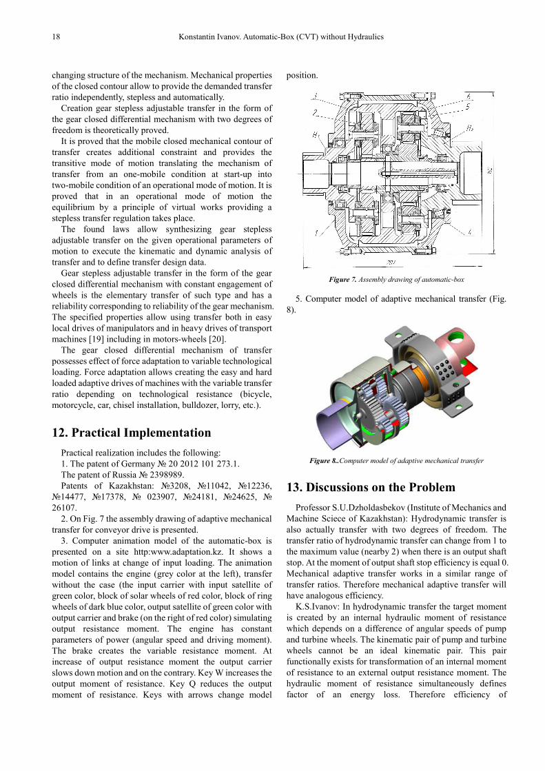
5. Computer model of adaptive mechanical transfer (Fig.
8).
Figure 8..Computer model of adaptive mechanical transfer
13. Discussions on the Problem
Professor S.U.Dzholdasbekov (Institute of Mechanics and
Machine Sciece of Kazakhstan): Hydrodynamic transfer is
also actually transfer with two degrees of freedom. The
transfer ratio of hydrodynamic transfer can change from 1 to
the maximum value (nearby 2) when there is an output shaft
stop. At the moment of output shaft stop efficiency is equal 0.
Mechanical adaptive transfer works in a similar range of
transfer ratios. Therefore mechanical adaptive transfer will
have analogous efficiency.
K.S.Ivanov: In hydrodynamic transfer the target moment
is created by an internal hydraulic moment of resistance
which depends on a difference of angular speeds of pump
and turbine wheels. The kinematic pair of pump and turbine
wheels cannot be an ideal kinematic pair. This pair
functionally exists for transformation of an internal moment
of resistance to an external output resistance moment. The
hydraulic moment of resistance simultaneously defines
factor of an energy loss. Therefore efficiency of

American Journal of Mechanics and Applications 2014; 2(6-1): 13-20 19
hydrodynamic transfer linearly decreases depending on
loading.
Basic other dependence occurs in mechanical adaptive
transfer. This dependence is defined by the formula (13),
connecting the external moments and speeds. The internal
mechanical moment in the closed contour of mechanical
adaptive transfer also occurs. However this moment does not
create energy loss, as power (or work) internal forces is
equal to null. In mechanical adaptive transfer there is only a
disproportionate of speeds of motion of links in the closed
contour.
Thus efficiency of mechanical adaptive transfer
functionally does not depend on external loading and
matches to efficiency of the planet gear. Efficiency instantly
gets a zero value at the moment of qualitative change of the
mechanism structure at stop of output link.
14. Conclusion
The automatic- box represents the gear differential with
two degrees of freedom which has a cogwheels closed
contour. The gear differential with two degrees of freedom
and one input containing the closed contour has the
adaptation to output loading and definability of motion.
Definability of a kinematic chain with two degrees of
freedom having only one input is paradox of mechanisms
and machines theory.
It is proved that gear differential with two degrees of
freedom containing closed contour has additional
geometrical constraint which provides definability of
motion in the presence of one input. Paradoxical additional
constraint takes place in a picture of speeds in the form of
instantaneous relative centre of rotation of satellite and
carrier. This additional constraint can be presented
structurally as passive superfluous constraint. Paradoxical
constraint analytically connects power and kinematic
parameters of an input and an output. This additional
analytical constraint is expression of force adaptation effect
which provides in the mechanism overcoming of variable
output loading at constant input power. Mechanical
properties of the closed contour allow to provide the
demanded transfer ratio independently, stepless and
automatically without use of hydraulics and application of
the control means changing geometrical parameters of the
mechanism.
The box-automatic in the form of gear differential with
constant engagement of cogwheels is a dream of designers
and inventors. It has fantastic advantages: extreme
simplicity of a design, small sizes, high efficiency and full
automatic adjustable. It is not surprising, that till now
nobody accepts new idea seriously.
References
[1] Levitsky N.I. Theory of mechanisms and machines. М, Science. 1979. 576 p.
[2] Ivanov K.S., Dmitrieva N.A. Without reaction engine. Copyright certificate of USSR №769157 from 7.09.1980. 8 p.
[3] Samuel J. Crockett. Shiftless, continuously-aligning transmission. Patent of USA 4,932,928, Cl. F16H 47/08, U.S. Cl. 475/51; 475/47.1990, 9 p.
[4] Wolkov I.V. Way of automatic and continuous change of the twisting moment and speed of rotation of a target shaft depending on resistance to motion and the device for its realisation. Invention description to the patent of Russia RU 2 234 626 from 27.03.2004. 16 p.
[5] Harries John. Power transmission system comprising two sets of epicyclic gears. Patent of Great Britain GB2238090 (A). 1991, 11 p.
[6] Ivanov K.S. Transfer with automatically adjustable speed. Preliminary patent of republic Kazakhstan № 3208 from 15.03.1996. 12 p.
[7] Ivanov K.S. Adaptive tooth gearing (variants). Preliminary patent RK №14477 from 13.04.2004. 9 p.
[8] Ivanov K.S., Yaroslavtsev E.K. Way of automatic and continuous change of the twisting moment and speed of rotation of a target shaft depending on resistance to motion and the device for its realisation. Patent of Russia RU № 2398989. 10.09.2010. 10 p.
[9] Ivanov Konstantin S., Almaty, KAZ - Owner of the registered sample. The name - Device of automatic and continuous change of a twisting moment – and changes of a corrected speed of output shaft depending on a tractive resistance. The deed on registration of the registered sample № 20 2012 101 273.1. Day of Registration 02.05.2012. German patent and firm establishment. Federal Republic Germany. 2012. 12 p.
[10] Ivanov K.S. The Question of the Synthesis of Mechanical Automatic Variable Speed Drives. Proceedings of the Ninth World Congress on the Theory of Machines and Mechanisms, Vol. 1, Politechnico di Milano, Italy, August 29-Sept 2, 1995. P. 580 – 584.
[11] Ivanov K.S. Discovery of the Force Adaptation Effect. Proceedings of the 11th World Congress on Mechanism and Machine Science V. 2. April 1 - 4, 2004, Tianjin, China. P. 581 - 585.
[12] Ivanov K.S. Gear Automatic Adaptive Variator with Constant Engagement of Gears. Proceedings of the 12th World Congress in Mechanism and Machine Science. Besancon. France. 2007, Vol. 2. P. 182 - 188.
[13] Ivanov K.S. The simplest automatic transfer box. WCE 2010. World Congress on Engineering 2010 (ICME) London, UK. 2010. P. 1179 – 1184.
[14] Ivanov K.S. Effect of force adaptation in mechanics. Journal of Mechanics Engineering and Automation. Vol. 1, N 3. Libertiville, USA. 2011. P. 163 – 180.
[15] Ivanov K.S. Toothed continuously variable transmission (CVT) for transport. EngOpt 2012 – 3rd International Conference on Engineering Optimization. Rio de Janeiro, Brazil, 01 - 05 July 2012. P. 211 – 218.
[16] Ivanov K.S. Paradox of theory of mechanisms and machines. Modern mechanical engineering. Science and education. Materials of 3rd International scientifically-practical conference. St.-Petersburg state polytechnical university. Union of machine engineers of Russia. St.-Petersburg. Russia. 2013. P. 146 – 156.

20 Konstantin Ivanov. Automatic-Box (CVT) without Hydraulics
[17] Ivanov K.S. Paradox in the Mechanism Science. 1-st International Symposium on the Education in Mechanism and Machine Science. Madrid. Spain. 2013. P. 132-138.
[18] Ivanov K.S. Paradox of mechanics – a basis of creation CVT. Transactions of 2-d IFToMM Asian Conference on Mechanisms and Machines Science. November 7-10, 2012, Tokyo, Japan. P. 245 – 264.
[19] Ivanov K.S. Drive of Extreme Transport Technique. Applied Mechanics and Materials. Vol. 245 (2013), Trans Tech. Publications, Swizerland. 2013. P 185-190.
[20] Ivanov K.S. Self-Adjusting Motor-Wheel with CVT. International Journal of Engineering and Innovanive Technology (IJEIT). Volume 2, Issue 4. Florida. USA. 2012. P.189 – 195.