automatic belt tension device - lu
TRANSCRIPT

DIVISION OF PRODUCT DEVELOPMENT | DEPARTMENT OF DESIGN SCIENCES FACULTY OF ENGINEERING LTH | LUND UNIVERSITY
2020
MASTER THESIS
Simon Önnered
Automatic Belt
Tension Device
Automatic Belt Tension Device
Development of a belt tensioning solution
Simon Önnered

Automatic Belt Tension Device
Development of a belt tensioning solution
Copyright © 2020 Simon Önnered
Published by
Department of Design Sciences
Faculty of Engineering LTH, Lund University
P.O. Box 118, SE-221 00 Lund, Sweden
Subject: Technical Design (MMKM10)
Division: Division of Product Development, Department of Design Sciences,
Faculty of Engineering LTH, Lund University
Supervisor: Damien Motte
Co-supervisor: Roger Dreyer (ASSA ABLOY Entrance Systems)
Examiner: Per Kristav

Abstract
In this master’s thesis, the development of a new belt tensioning solution, for use in
ASSA ABLOY's sliding doors is treated.
As a starting point for the work, ASSA ABLOY’s current belt tension solution has
been used as a reference. On this reference, an extensive problem analysis have been
carried out, including interviews, field studies and laboratory tests in order to understand what is required of a final solution. The problem analysis both resulted
in actual problems to be solved, but also produced various requirements and
recommendations to take into account in the development process. Together with a
literature study, these were the basis for concept generation to find different ways
to solve the identified problems.
The generated concepts have been partly evaluated qualitatively together with
employees at ASSA ABLOY and partly against the requirements and recommendations, which has resulted in a selection of concepts that have been
further developed.
The selected concepts have been divided into categories of short, medium-long and
long term, depending on how early an implementation of the concept have been estimated to be. Among these concepts, one concept was chosen from the medium-
long perspective to further develop. The concept uses an eccentric wheel to generate
the belt tension and a spring to indicate the installation tension. A test was conducted to achieve Proof of Concept for the tensioning method. The result from the test was
positive and led to the creation of a 3D-prototype.
Finally, concepts were suggested that were considered to have potential for further
development, and what benefits they would entail.
Keywords: Belt tension, timing belt, sliding doors, problem analysis, eccentric,
ASSA ABLOY

Sammanfattning
I detta examensarbete behandlas utvecklingen av en ny remspänningslösning för
användning i ASSA ABLOYs skjutdörrar.
Som utgångspunkt för arbetet har ASSA ABLOYs nuvarande remspänningslösning
använts som referens. På denna referens har en utförlig problemanalys genomförts
vilken innefattat bland annat intervjuer, fältstudier och laboratorietester för att på så vis förstå vad som krävs av en slutlig lösning. Problemanalysen har både resulterat
i faktiska problem att lösa, men också frambringat olika krav och rekommendationer
att ta hänsyn till i utvecklingsprocessen. Tillsammans med en litteraturstudie har
dessa varit underlag för en konceptgenerering för att finna olika sätt att lösa de
identifierade problemen.
De genererade koncepten har dels kvalitativt utvärderades tillsammans med
anställda på ASSA ABLOY, dels ställts mot de krav och rekommendationer som
funnits vilket har resulterat i ett urval av koncept som utvecklats vidare.
De valda koncepten har delats in i kategorier om kort, medellång och lång sikt
beroende på hur tidigt en implementering av konceptet har bedömts kunnat vara.
Bland koncepten valdes ett koncept valts ur det medellånga perspektivet att vidareutveckla. Konceptet bygger på att ett excentriskt hjul generar remspänningen
och en fjäder indikerar remspänningen vid installation. Ett test gjordes för att uppnå
Proof of Concept för uppspänningmetoden. Resultatet från testet var positivt och
ledde till att en 3D-prototyp skapades.
Avslutningsvis föreslogs koncept som ansågs ha potential för fortsatt utveckling,
och vilka fördelar de skulle innebära.
Nyckelord:
Remspänning, kuggrem, skjutdörrar, problemanalys, excentrisk, ASSA ABLOY

Acknowledgments
I would like to thank all the employees at ASSA ABLOY in Landskrona who have
helped me to complete this master’s thesis. A special thanks goes out to my supervisor Roger Dreyer that have supervised me and always helped me forward in
the process. Also, a big thanks to Fredrik Hambert and Sara Roos who have given
valuable inputs on the way.
I would also like to thanks my supervisor Damien Motte, my examiner Per Kristav
and my opponent Stefan Lopar for giving me much valuable feedback on my report
which have helped me completing it.
Lund, June 2020
Simon Önnered

Table of contents
1 Introduction 9
1.1 Background 9
1.2 Purpose 9
1.3 Initial delimitations 9
2 Project methodology 11
2.1 Design process methodology 11
2.2 Adopted process 12
3 Discover 13
3.1 Sliding doors theory 13
3.2 Timing belts theory 14
3.3 Current solution analysis 18
3.4 Competitor analysis 21
4 Define 23
4.1 Problem identification 23
4.2 Requirements and recommendations 27
5 Develop 30
5.1 Concept generation 30
5.2 1st Concept selection 45
5.3 1st concept development 47
5.4 2nd concept selection 53
5.5 2nd concept development 53
6 Deliver 55
6.1 Prototyping 55
7 Discussion 60
7.1 Suggestions 60

7.2 Further development 61
8 Conclusion Error! Bookmark not defined.
8.1 Self-reflection 62
8.2 Planning Error! Bookmark not defined.
References 63
Appendix A Belt and shaft forces equations at operational load 64
Appendix B Testing 67
B.1 Lost pre-tension 67
B.2 Thermal expansion 70
Appendix C Competitors analysis 73
Appendix D Field observation notes 75
Appendix E Interviews 76
E.1 Installation Technician 76
E.2 Service Manager 78
E.3 Product Specialist 81
Appendix F Test lab observations 87
F.1 Identified problems 87
F.2 Notes. 87

9
1 Introduction
This chapter will cover the background and purpose of this master’s thesis, as well
as some initial delimitations.
1.1 Background
One main component in sliding doors are timing belt which converts a drive unit’s rotational movement into a linear ditto. In order for the sliding doors’ functionality
to be guaranteed, these belts must be correctly tensioned at all time. For various
reasons, this may not always be true. Incorrect installation, component failure or external factors, such as temperature variations in the operating environment, are
some factors that can affect the functionality of the belt drive.
The solution that ASSA ABLOY currently use in their sliding doors, has not been
changed for many years, and some complaints about it have been heard from technicians, whereupon a suspicion, that a more effective solution exists, has risen.
Perhaps is there a solution which tensions the belt automatically?
1.2 Purpose
ASSA ABLOY wishes that, within the scope of this master’s thesis, the problems
related to current solution are thoroughly examined and that a new improved solution is developed where these problems are solved. The possibility of
developing an automatic tensioning solution will also be investigated.
1.3 Initial delimitations
During the planning of the project, it was decided that only solutions which operates
the doors using timing belts were to be developed. It was also decided that ASSA
ABLOY’s sliding door system SL500, which has a vertically installed timing belt,

10
was to be used as reference. Finally, it was decided that only bi-parting (two doors)
sliding doors configurations were to be investigated.

11
2 Project methodology
This chapter contains the methodology that has been guiding the project
throughout, and how it was adopted.
2.1 Design process methodology
Figure 1 Double Diamond methodology
To structure the work in this master’s thesis project, the Double Diamond
methodology (Design Council, 2020) has been used, as well as elements from Ulrich
and Eppinger (2012) where appropriate. The double diamond methodology consist
of four parts which can be found in Figure 1. The principle is that it is expanded, narrowed, expanded and finally narrowed down. The content in each phase are not
rigid and may differ from project to project. For this project the contents have been
the following:
Discover - Information was gathered about relevant subjects related to the general
problem or idea, upon which the project was based, e.g. through performing
literature studies and field studies.

12
Define - The information gathered in the discovering phase was narrowed down to
define specific problems to be solved. Needs and requirements were also identified.
Develop - Different concepts were generated and developed based on the specific
problems. Concept selection was made.
Deliver – Based on the findings in the previous three steps, a solution was created.
The Double Diamond methodology is carried out from left to right. However, this
is not a strict rule. Every project is unique and will have its own unique process. The Design Council, creator of the methodology, emphasizes that the methodology is
not linear, but should rather be used as a framework from which to build upon.
Jumping between diamond segments are not only allowed, but encouraged, in order to get the most out of the methodology. What each segment will contain, is also
somewhat free for the user to decide.
2.2 Adopted process
Figure 2 Adopted process in Double Diamond
The adopted design process for this project can be found in Figure 2. Methods e.g.
interviews, testing etc. related to each element will be described when treated in the
report. In addition to this, planning was carried out before project start and analyses,
conclusions and discussion were done after the delivering phase was finished.

13
3 Discover
In the Discover chapter, information necessary to understand the problems with belt
tensioning in general and information about ASSA ABLOY’s belt tensioning
solution specifically is presented.
3.1 Sliding doors theory
Automatic sliding doors (ASD) can be found in various places. Hospitals, libraries,
offices, schools and stores are just a few examples. ASD systems in buildings can
provide more comfortable movement within it, especially for people with motoric disabilities, as no human force is require to open them. The fact that no physical contact is needed also makes them ideal from a hygienic perspective.
Figure 3 Typical bi-parting (two doors) ASD system
The working principle in a typical ASD system is fairly straightforward. The upper
compartment of an ASD system, Figure 3, contains a drive unit with a pulley attached to it (1), an idler pulley (2), a timing belt (3) and a door carrier (4) on each
door. The belt travels around the two pulleys which make the upper and lower belt
segment move in opposite directions. In the case of a double sided ASD, one door
carrier is attached to the upper belt segment and the other to the lower. When the drive unit rotates its pulley clockwise, in a configuration like the one in Figure 3,
the doors will move outwards. Conversely, when the drive unit rotates its pulley
counter-clockwise, the doors will move inwards. A single ASD, Figure 4, functions by the same principle as a double sided ASD, except there is only one door.

14
Consequently, the door carrier is only attached to either the upper or the lower belt segment.
Figure 4 A single (one door) ASD
3.2 Timing belts theory
The theory in the following two sections is collected from the Timing Belt
Handbook (Perneder & Osborne, 2012).
3.2.1 What is a timing belt drive?
Timing belt drives consists of timing belts, also known as synchronous or toothed
belts, and timing pulleys. It is a type of positive drive, meaning no slip must be
involved in transmission, which is possible in friction drives. Its characteristics can
be derived from the name synchronous belt drive, which describes a drive where all components connected to the drive move synchronically in relation to one another.
The main difference between timing belt drives and chain drives, is that the latter is
made up of linked segments while the former has more of a continuous shape.
Timing belts consists of a belt with elastic cogs. Although, different timing belts
have different cog profiles, their function is fundamentally the same. Just as timing
belts have different profiles, timing pulleys have different teeth profiles to match
the belts’. These are rigid and shaped to provide best possible meshing with its
associated belt.
An elastic material, such as synthetic rubber or polyurethane, is commonly used for
the belt material. Some belts are reinforced with tension members made from a stronger material than what the belt is made of, such as steel or various fibers. These
are incorporated into the belt, see Figure 5, as single or stranded cables to provide
better mechanical properties.

15
Figure 5 Tension members in a timing belt (Perneder & Osborne, 2012, p. 35)
The working principle of timing belt drives is straightforward. A drive unit exerts a
torque onto a pulley, called the driven pulley. In turn, the driven pulley’s teeth will exert a force onto the timing belt’s teeth, affecting its motion. The torque direction
decides which flanks of the teeth will be exerted to force. Note, the direction of
torque may be different from the rotational velocity direction. This is the case when
braking.
3.2.2 Why use timing belt drives in sliding doors?
The synchronous behavior that is characteristic for timing belt drives makes them ideal for linear positioning applications, such as sliding doors, as the position of the
moving objects are highly predictable. Because one turn on the driving pulley will,
more or less, always result in linearly moving the belt, and whatever is attached to
it, the distance of the pulleys circumference. Whereas for friction drives, where the
chances of slippage is ever-present, this is not the case.
In terms of noise, timing belt drives holds an advantage over chain drives by
operating more continuously than chains which consists of separate segments. Another advantage with timing belts drives over chain drives is that lubrication is
mostly not needed.
In sliding doors operation, quick acceleration, deceleration (braking) and change of
direction occurs all the time. For applications with this dynamic behavior, timing belts are the preferred choice. Because the teeth are elastic, the change of flanks will
be executed smoothly.

16
3.2.3 Pre-tension
When installing a timing belt, it is important that it is sufficiently pre-tensioned to
function correctly. Failure to do so could result in bad belt meshing and tooth jumping, meaning the pulley misses a cog, compromising the belt drive’s
positioning function. The pre-tension, Ti, in a two-pulley drive is obtained by
increasing the distance between the pulleys to the point where the belt starts to elastically deform. The elongation develops a tensile force in the belt. This force is
the pre-tension and it is theoretically the same throughout the entire belt span when
in its idle state, see Figure 6. Note, in the figure, it may look like the pre-tension
force is directed outwards, which is not the case. This way of illustrating the belt force is used to easier see which part of the belt has the specified tensile force. Also,
when more forces are present, e.g. in operation, the relative size of the forces can
easily be pictured, using this way of presenting the forces. This becomes clearer in
Appendix A. (Gates Mectrol Inc., 2006)
Figure 6 Pre-tension in belt, adapted from (Gates Mectrol Inc., 2006, p. 6)
Some belts may need re-tensioning after some time of operation, as they lose some
of their initial pre-tension. This is due to a settling behavior in the belt’s tension
members (Perneder & Osborne, 2012).
3.2.4 Shaft forces – Idle state
The shaft forces are reaction forces to the belt forces. They are exerted to the
bearings of the pulleys. These forces can easily be derived from Figure 6. In idle
state the shaft forces are:
𝐹𝑠1 = 𝐹𝑠2 = 2 ∙ 𝑇𝑖 (3.1)
They are dimensioning for the pulley’s bearings. The bearing’s static force
capacity must exceed that of the static shaft forces.

17
3.2.5 Belt sag - operational
When a belt drive, with direction changes and braking actions, operates, the belt
forces changes. Some belt segments will have higher tension than the pre-tension and some will have lower. The segment with lower belt tension may show a sagging
behavior, see Figure 7. This will affect the belt’s meshing with the pulley negatively,
and can possibly cause tooth jumping. It is therefore important, that the slack belt segment always have sufficient tension for good pulley meshing. How much
sufficient tension is, may vary from case to case. (Perneder & Osborne, 2012)
Figure 7 Belt sag on lower belt segment
3.2.6 Belt forces - operational
Equations to calculate the belt forces in a linear positioning belt drive in operation
can be found in Appendix A. These equations requires neglectable belt sag. Though, when observing ASSA ABLOY’s widest doors in test lab, it is obvious that this
cannot be done as belt sag is very pronounced. The fact that ASSA ABLOYS current
solution also is equipped with springs, which will be described later, makes these
equations highly inaccurate. The equations are still included in the appendix as they
are thought to be helpful for understanding belt drives in general.
3.2.7 Thermal expansion
When the temperature is elevated, many materials increase in size due to what is
called thermal expansion. Though, the amount they expand differ for every material.
Conversely, when temperatures are lowered, the material will reduce its size (Tipler
& Mosca, 2008).
Sliding doors constructions may consist of both aluminum, in an extruded profile
where the pulleys are fixated, and steel, in the belt’s tension members. With different

18
thermal expansion coefficients, see Table 1, for these materials, in theory, the
different components will elongate differently causing changes in belt tension.
Table 1 Thermal Expansion Coefficients (Perneder & Osborne, 2012)
Material Thermal expansion coefficient (10-6∙1/K)
Steel 12∙10-6 in 1/K
Aluminum 24∙10-6 in 1/K
3.2.8 Timing belt tensioning principles
Like in most areas, there are rules which needs to be followed when designing, and
timing belt drives is not an exception. Below, some principles collected from the
Timing Belt Handbook (Perneder & Osborne, 2012) are presented:
In belt pre-tensioning solutions the idle pulley must be secured when the
belt has reached its recommended pre-tension, i.e. it must not be sprung or dampened.
Sprung external tensioner onto the belt (not sprung idler pulleys) can be
used in some applications. However, in belt drives with change of torque
direction, e.g. at direction change or braking, they must not be used.
The pre-tension of the belt should be set so that at worst case, the slack belt
segment always has some tension.
3.3 Current solution analysis
3.3.1 Working principle
ASSA ABLOY’s current belt tension solution (BTS), can be found in Figure 8,
Figure 9 and Figure 10.

19
Figure 8 Front view of current BTS
Figure 9 Side view of current BTS

20
Figure 10 Exploded view of current BTS
To install the BTS the following steps are followed (all numbers refer to Figure 8,
Figure 9 and Figure 10):
1. The screw (1) is untightened.
2. The BTS is placed in the aluminum profile’s C-track (2) and pushed to the
right obtain some belt tension. 3. The BTS is locked in place tightening the two screws (3).
4. The tensioning screw (4) is then tightened until there is a 1-2 mm gap
between the lock nut (5) and the idler pulley bracket (6).
5. Finally, the screw (1) is tightened.
The working principle of the current BTS is that the tensioning screw pushes the
idler pulley (7) to the right along a rounded long hole in the mounting bracket (8),
tightening the timing belt (9). It is tightened solely due to the screw pushing it to the right until the spring (10) starts to deflect. Then the screw pushes the idler pulley to
the right while the latter is resting on the spring. The spring is pre-tensioned so that
a 1-2 mm gap between the idler pulley bracket and the lock nut corresponds to a deflected spring length of 42-43 mm. This deflection equals a belt tension of around
80N. The spring will be deflected by twice that force, 160N, because it is pulled by
two belt ends.
On wide doors, one or two springs, which ASSA ABLOY refers to as slack reducers,
see Figure 11, are attached to the belt above the door carriers. These are meant to
ensure that there is always some tension in the belt. When belt sag develops in the
belt, the slack reducer pulls the belt to counteract the sag. Adding two of these to the belt drive increase the belt pre-tension with approximately 20 N each to 100N
or 200N in pre-tension shaft force.

21
Figure 11 Slack reducer attached to the belt at the door carrier
No specific pre-tension interval, in which the belt drive can operate correctly, have
been found in ASSA ABLOY’s documentation.
3.3.2 Materials
Most of the parts are made from steel, but there are some exceptions. The belt is made from a thermoplastic polyester, a type of polymer, reinforced with steel
tension members. The idler pulley is made from PA66, a type of nylon polymer.
Finally, two mounting washers (11) are made from LDPE, also a polymer. The
extruded profile is made from aluminum.
3.4 Competitor analysis
The goal of the competitor analysis has been to gather information and inspiration from competitors’ belt tensioning solutions. This has been done by looking at
installation and service manuals for four different sliding doors. It is important to
mention that no guarantee can be given for that these solutions actually are successful, as the tensioning devices and methods have not been tested within this
master’s thesis. Illustrations of the competitors’ solutions are found in Appendix C.

22
3.4.1.1 Tensioning method
Tensioning is done in several different ways, but leverage plays a central role in all
of them. The pre-tension is obtained in the following ways:
A screw gradually moves the idler pulley as it is turned.
The idler wheel pulley is moved by using a screwdriver to push the idler
pulley assembly in place.
The drive unit and idler pulley assembly is partly fastened when some belt
tension can be observed. When fully fastened, there is leverage which gives
the final pre-tension.
3.4.1.2 Controlling tension
Most of the solutions do not include methods to accurately control the tension after
being installed. They mostly rely on the installation or service technicians’
experience which most likely result in rather inconsistent tensions. However,
whether this is crucial for the operation in each case cannot be determined.
3.4.1.3 Placement
Most idler pulley assemblies in the analysis is mounted in the roof of the extruded
profile. Because any flexing in the construction will be more in line with the belt,
compared to wall mounting, this configuration probably provides best possible belt
alignment with the idler pulley.
3.4.1.4 Tools
Both configurations which requires only one and two tools simultaneously can be
found. No special tools which are not readably available are required for any
solution.

23
4 Define
In this chapter, specific problems are specified to be addressed and solved in the
concept generation phase. Requirements and recommendations from ASSA ABLOY
are also included.
4.1 Problem identification
4.1.1 Methods
To collect information about which problems are related to the current BTS a couple
of different methods have been used. These methods were chosen, because they
were all thought to contribute with valuable input to the project.
4.1.1.1 Observations in test lab
By making observations in the test lab, see Appendix F, it was possible to perform the Current solution analysis, presented in section 3.3, to get a good understanding
of the working principle of the current solution and its problems.
4.1.1.2 Tests in test lab
To analyze some properties of the current belt tensioning solution, two tests have
been conducted. The tests in the test lab enabled to take measurements which are not possible to make at actual installation sites. It also enabled testing worst case
scenarios, such as maximum door weight and width. The two tests addressed lost-
pre-tension and temperature adaptation and their associated test report can be found
in Appendix B.
4.1.1.3 Field observations
Both an installation and a service technician were observed while they performed
their work routine. By observing them, it was possible to get an understanding of
what their reality looks like and what needs be considered for a solution to be eligible for them. Also, some discussion opened up for more inputs. Some notes

24
from the field observation with the service technician were documented, see
Appendix D.
4.1.1.4 Interviews
The goal of the interviews was to obtain as much information about the current
solution as possible to receive a deeper understanding for it. Both positive and negative aspects were of interest. Interviews with one installation technician, one
service manager and one product specialist were conducted, see Appendix E. The
service manager have good contact with a large number of service technicians and
the product specialist knows a lot about the current tensioning solution’s specifics and what technicians think about it. By interviewing people in different positions
within the company, different perspectives of the current solution, and problems
associated with it, could be captured. The interviews were semi-structured (Sharp, Preece, & Rogers, 2019). This interview type was chosen as it was thought to be the
most effective to obtain the wanted information. Also, the use of follow-up
questions, characteristic for semi-structured interviews, was thought to enrich the
interview with more substantiated answers.
4.1.2 Identified problems and probable causes
From the data collecting methods above, the following problems have been
identified.
4.1.2.1 Incorrect tension
When installing the belt, the gap between a lock nut and the idler pulley bracket is
supposed to indicate when correct tension has been obtained. However, it is possible
that the lock nut’s position is changed when the screw is turned, which makes this indicator inaccurate. What really is of interest is the spring deflection when the idler
wheel is resting solely on the spring, as this directly correlated to the belt tension.
The fact that it is even possible to both over and under tension the belt with current
solution will contribute to some doors being installed with incorrect belt tension.
4.1.2.2 Noise
This problem can have multiple possible causes. One is that the belt is not aligned
with the idler pulley making the belt “climb” on the idler pulley’s flanges. This
misalignment could either be caused by the fact that the entire idler pulley unit is
rocking up and down in operation, see Figure 12. The slack reducer twisting the belt
may also contributes to some misalignment.

25
Figure 12 Rocking motion due to lack of wall support
Noise can also be caused by the belt being tensioned to tight. The belt is then rubbing against the idler pulley’s teeth. The noise is similar to that of plastic rubbing against
rubber.
The fact that the idler pulley is made from plastic may also have an impact. As a reference, the belts interaction with the drive unit’s pulley, which is made from steel,
was not commented in any interview, which suggest that it is more silent.
Another source of noise, observed in the test lab, is when the upper belt segment
sags, making it interfere with the slack reducer on the lower belt segment causing a
noise, see Figure 13.
Figure 13 Upper belt segment interfering with lower belt segment’s slack reducer
4.1.2.3 Lost grip in C-track
If the idler pulley assembly loses its grip in the aluminum profile’s C-track, the belt tension will decrease, compromising the sliding doors function. If the grip is
completely lost, a reinstallation of the belt will have to be done. One probable cause

26
for this is that it is difficult to provide sufficient force to secure the screws which
fastens the idler pulley assembly to the aluminum profile.
Another probable cause is that the rocking motion, illustrated in Figure 12, is similar
to vibrations. It is well known that screws can come loose if subjected to vibrations.
It is possible that this rocking motion have a similar affect to these screws.
4.1.2.4 Difficult to install in C-track
From the service technician interview, this problem can be interpreted to be directly
related to the problem with lost grip in the C-track. If the problem with lost C-track
is caused by insufficient force when securing the torx-screws, which fastens the idler pulley unit to the aluminum profile, then this problem is because of the torx-screws
can’t easily be accessed with tools providing enough force.
There is also the possibility that the screws actually are sufficiently tensioned, but that the rocking motion, due to lack of idler pulley unit wall support, is the root
cause and that the current screws with current tensioning force are sufficient.
4.1.2.5 Lost pre-tension
From testing, see Appendix B, it appears as if the current belt has a slight settling
behavior which result in a decrease in pre-tension after a couple of cycles.
4.1.2.6 Temperature dependency
From testing, see Appendix B, there is evidently a significant temperature dependency in the current belt tensioning solution, most likely caused by the
different materials in the extruded profile and the belt’s tension members. Although
the pre-tension difference did not compromise functionality in the conducted test, it has to be mentioned that the test did not test the widest possible door width
configuration, due to limited space in the climate chamber. Belt sag, accompanied
by the decrease in belt tension, could be a more frequent problem for wider doors.
Also, only installation at 15°C was tested. Differences in performance could possibly have been observed if the belt had been installed at the lowest or highest
possible temperatures.
4.1.2.7 Damaged idler pulley
The idler pulley could be damaged in two ways. The first, is that the technician can
accidentally screw the tensioning screw too far causing it to drill into the pulleys teeth. This can happen if the idler pulley unit has not been pushed enough in the C-
track. The second, is that the securing screw in the idler wheel center becomes loose
causing the pulley to crash into the tensioning screw. The placement of the screw
and the lack of any fail-safe feature makes this possible.

27
4.1.2.8 Difficult to install slack reducers
The slack reducers are considered cumbersome to handle by the technicians. The fact that technicians try to work around them by adding more belt tension instead,
suggests that they dislike them.
4.1.2.9 Tooth jumping
This problem is most common in very wide doors. It is caused by the belt sagging.
The belt sagging can have multiple causes. The first, is that the belt has been insufficiently tensioned, because the technician has not followed the instructions.
The second, is that the temperature has decrease causing the belt to lose some
tension making it sag more. A third, can be the belt settling behavior causing the
belt tension to drop below sufficient tension.
4.1.3 Problem magnitude
It is difficult to determine the magnitude of problems above. Since the interviews only provide a sample of estimates and opinions about the current solution, they
cannot, for sure, be said to general. Although the magnitude is left unknown,
solutions to the problems will be attempted to be found.
4.2 Requirements and recommendations
In collaboration with ASSA ABLOY some strict specification requirement, that a
BTS must fulfill, have been given. Also, recommendations, which a solution does not have to comply with, but are highly desired, have been possible to extract from
talking with ASSA ABLOY employees. A classification, similar to that used in
Ulrich and Eppinger (2012), have been used.
4.2.1 Requirements
1. The BTS must function for all types of ASSA ABLOY sliding doors i.e.
single slide, bi-parting and telescopic doors. 2. The BTS must be able to handle up to 6 m wide doors, which is the widest
sliding door configuration ASSA ABLOY offers.
3. The BTS must be able to handle door leaf weights up to 200 kg (which equals a total weight of 400 kg in bi-parting doors) which are the heaviest
doors ASSA ABLOY offers.

28
4. The BTS must be able to handle operating temperatures between -20°C and
+50°C.
5. The static shaft force provided by the BTS must not exceed the drive unit
bearing’s capacity of 300 N. 6. The BTS must be physically easy to install to not expose the technicians to
any risk when handling it.
Due to number 5, it is not an option to install the timing belt at a much higher tension than it is today. If it were, the belt sag problem could be approached by giving the
belt more pre-tension. Though, this action may result in new problems, such as
higher electricity consumption or noise.
4.2.2 Recommendations
1. The BTS installation time is short
2. The BTS can be installed with few tools 3. The BTS maintenance time is short
4. The BTS can be maintained with few tools
5. The BTS is fail-safe in its construction
6. The BTS provides silent operation 7. The BTS is durable
8. The BTS can handle temperature changes
9. The BTS has a low manufacturing cost 10. The BTS tension can be read off
Number 8, in the recommendation, about handling temperature changes is especially interesting. The test in Appendix B suggest that the belt tension changes
significantly with shifting temperatures. It can be interpreted that the belt should be
installed at a tension which takes installation temperature in consideration. For
example, if the temperature is very low when the belt is installed, the belt should be installed at a lower tension to avoid the belt becomes over-tensioned when the
temperature increases over time. Conversely, the belt should be installed at a higher
tension if the temperature is high when installing, to not risk sagging if temperature drops over time. This suggests that temperature dependent installation tension is of
interest. However, another way of approaching this is to make assumptions about
the temperature at the installation. What is really the probability that a door installed at -20°C will face temperatures of +50°C in the future and vice versa? Is it possible
that the temperature interval in which the door operates is not big enough to cause
any tensioning problems? There is no obvious answer to how this problem should
be approached. Therefore, based on this short discussion, both concepts that take temperature in consideration and solutions which do not, have been of interest in
the concept generation phase.

29
4.2.3 Delimitation
The test about lost pre-tension in Appendix B, suggests that some way of tackling
the problem with the belt’s settling behavior is needed. However, solving this problem, in a way which does not involve changing the timing belt, requires more
investigation which has been thought to be outside the scope of this project and was
therefore not looked further into from this point.
30
5 Develop
This chapter will include the process of generating concepts to solve some of the
identified problems, followed by two iterations of concept development and concept
selection.
5.1 Concept generation
5.1.1 Method – Brainstorming
A brainstorming activity together with four employees at ASSA ABLOY Entrance
Systems with insight on the current BTS was held with the goal of finding as many
creative solutions for a new BTS as possible. This involved brainstorming general tensioning methods, and thinking about how to avoid the identified problems, with
the current BTS’s. As there were many problems with the current BTS, the
brainstorming activity had to be narrowed down to address only a small selection,
in order to make it manageable. The following topics were discussed:
In which ways can a belt be tensioned?
In which ways is it possible to determine the belt’s tension when installing
or servicing?
How would it be possible to make the belt adapt to temperature changes?
How can belt alignment issues, one possible cause for noise, be solved?
Is there a solution which solves/combines all these problems/solutions?
Other ideas
5.1.2 Generated concepts and screening
The brainstorming activity, together with some ideas which had been thought of
previously during the project, yielded a couple of concepts which were divided in
six different categories (listed below) depending on which problem they address. A
few concepts do not have an illustration, instead, these are explained in text.

31
Concept categories:
A. Belt tensioning methods
B. Correct tension indicators
C. Reduce belt sagging D. Alignment – Silent operation
E. Silent operation (not alignment related)
F. Temperature adaptation
The concepts were discussed upon at a later point with roughly the same people who
participated in the brainstorming activity, to eliminate ideas which the group thought
lacked potential. This section includes pros and cons with the different concepts as
well as information about whether or not the concept was decided to proceed with.
Accordingly with Ulrich and Eppinger’s (2012) concept development process, a
screening to sort out undesired concept, was conducted.
5.1.2.1 Belt tensioning methods
In this section different belt tensioning method concepts are presented (Figure 15-
Figure 22).
A1. Leverage – External tool
Figure 14 Leverage – External tool
An external tool is used to push the idler wheel obtaining pre-tension. It was discussed that the result may differ depending on which screwdriver the technician
had access to. However, sufficient tension was thought to be obtained quickly
which made the concept proceed.

32
A2. Leverage – Hand
Figure 15 Leverage – Hand
Instead of using an external tool like in Concept A1, the “tools” is built into
construction. The group thought it would probably be too bulky and would require
a rather complex mechanism. Therefore, the concept did not proceed.
A3. Leverage – Gravitational
Figure 16 Leverage – Gravitational
In this concept a mass linked to a levering arm provides the tension. All ways of using a weight, both as an external tool and as part of the construction, were thought
to add too much mass, either to the technicians toolbox or the construction. The
concept did not proceed.

33
A4. Screw - External tool
Figure 17 Screw - External tool
This is the working principle which the current solution builds upon. A pulling and a pushing configuration of the concept is illustrated in Figure 17. The principle is
proven to work relatively well in current solution and a future concept including it
was thought to be space-efficient. The concept proceeded.
A5. Snowboard boot inspired tension BOA®
Figure 18 Snowboard boot inspired tension BOA®
A tensioning device like the ones used in snowboard boots. However, the company
developing the tensioning system does not provide any data on how much force the
system can handle and was therefore not proceeded with.

34
A6. Eccentric wheel
Figure 19 Eccentric wheel
By turning an eccentric wheel, the idler pulley is pushed, tensioning the belt. An eccentric wheel is used successfully in another part of ASSA ABLOY’s sliding
doors. Using the concept in tensioning the wheel was thought to be interesting and
the concept proceeded.
A7. Stepper motor
Figure 20 Stepper motor
A stepper motor, connected to a screw, tensions the wheel without any human force.
The concept was thought to be futuristic with possibility to make automatically
adjustable. The concept proceeded.
35
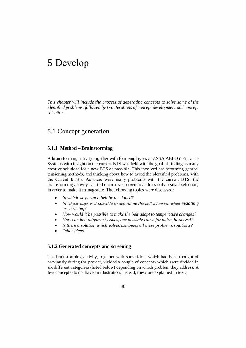
A8. Mainspring
Figure 21 Mainspring
The force is obtained by a mainspring. No theory supporting this would work in
reality was found and the concept did not proceed.
5.1.2.2 Correct tension indicators
In this section, different ways of indicating the tension is presented, Figure 22-
Figure 28.
B1. Spring + Indicator scale
Figure 22 Spring + Indicator scale
The deflection of the spring is read off on a scale or other visual representation.
Being able to read the tension was something that was requested from technicians,
and the concept was therefore thought to be of interest. The concept proceeded.

36
B2. Spring + Hole indicator
Figure 23 Spring + Hole indicator
The working principle is that the spring is deflected to a specific point where two
holes align. A benefit with this solution is that the tension can be controlled both
tactically, by testing if a tool can pass through, and visually. The concept proceeded.
B3. Spring + Tactile and visual scale
Figure 24 Spring + Tactile and visual scale
Similarly to concept B2, the tension can be controlled both tactically and visually, but instead of a hole there is a sharp edge in a gap which indicates the tension. The
concept was thought to have potential and was proceeded with.

37
B4. Spring + Cut of tube 1
Figure 25 Spring + Cut of tube 1
The use of tube the length of the desired spring deflection would limit the tension to not risk over-tensioning the belt. This would also increase consistency in belt
tension among installed sliding doors. The simplicity and provided consistency,
made the concept proceed.
B5. Spring + Cut of tube 2
Figure 26 Spring + Cut of tube 2
Similar to Concept B4, but the slit in the tube making them interchangeable, if for
any reason different tension is desired. However, the team did not like the idea of
having loose parts in the construction and the concept did not proceed.
38
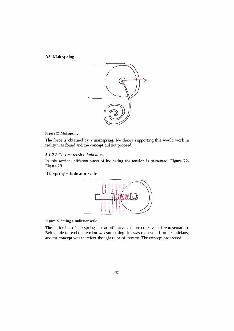
B6. Strain gauge
Figure 27 Strain gauge
A strain gauge, which can measure tension by measuring resistance in an electric
circuit, can be used to measure the tension. A configuration which can read the
tension when in operation is possible, in contrast to Concepts B1-B6, where tension only can be read when idler wheel is not secured. Even though it is a solution which
requires electricity, it was thought to have potential in next generation BTS. The
concept proceeded.
B7. Measuring device
There are devices that can measure belt tension, however these are expensive and the probability of incorrect use were thought be too high to be considered. The
concept did not proceed.
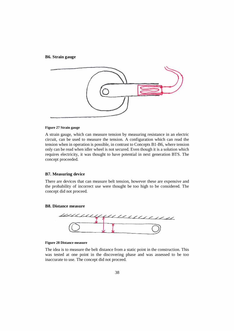
B8. Distance measure
Figure 28 Distance measure
The idea is to measure the belt distance from a static point in the construction. This
was tested at one point in the discovering phase and was assessed to be too
inaccurate to use. The concept did not proceed.

39
B9. Auditory feedback
This concept builds upon the idea of having some sort of auditory feedback, such as
a clicking sound, when a desired tension is obtained. Though, some doors are
installed at noisy places and missing out the feedback would leave the technician in
uncertainty. The concept did not proceed.
5.1.2.3 Reduce belt sagging
In this section, different ways of reducing belt sag is presented, Figure 29-Figure
32.
C1. Self-helping belt support
Figure 29. Self-helping belt support
This is an attachment which is fitted to the belt. The idea is to provide support to the
belt where and when it is needed. When the upper belt is tight and the lower is slack,
the upper belt would lift the lower and vice versa. The concept was thought to be
interesting and proceeded.

40
C2. Support structure
Figure 30 Support structure
A static belt support attached to the fixed construction supports the belt making the sag less pronounced. The concept was thought to be simple yet functional and
proceeded.
C3. Change drive unit position
Figure 31 Change drive unit position
At its current position the belt is unnecessary long in some doors. By moving the drive unit, the belt length can be reduced and as a result the belt would sag less. The
concept was thought to be a simple thing to test and proceeded.
C4. Spring wheel tensioner on belt
Figure 32 Spring wheel tensioner on belt

41
A spring is used to counteract the belt sagging. This concept is not recommended,
which is stated in 3.2.8 Timing belt tensioning . The concept did not proceed.
C5. Software modifications
From the sliding door’s software, it is possible to change the drive unit’s torque.
This would result in the belt sagging less. However, the group decided that it is not
an option to reduce performance. The concept did not proceed.
5.1.2.4 Alignment – Silent operation
In this section, different concept which attempts to keep the belt aligned, making
operation silent, is presented, Figure 33-Figure 37.
D1. Wider wall support distance
Figure 33 Wider wall support distance
By increasing the distance between the screws which attach the idler wheel
assembly to the fixed structure, the overall construction is thought to be sturdier.
The concept proceeded.
D2. Roof fixture
Figure 34 Roof fixture
The idea is to place the idler pulley assembly in the extruded profiles roof to provide better belt alignment. Although it is not compatible with the current interface, the
concept was thought to be of interest. The fact that it is used by many competitors
suggests that it is an efficient way of maintaining the belt aligned with the idler
pulley. The concept proceeded.

42
D3. Wall support – block
Figure 35 Wall support – block
By adding a block made out rubber, for example, the idler pulley construction would
be supported against the wall counteracting any rocking motion caused by force changes. This was thought of as a very simple way of solving the problem with the
rocking motion and the concept proceeded.
D4. Wall support – screw
Figure 36 Wall support – screw
Similar to concept D4, but instead a screw in a threaded hole makes it possible to
adjust the support distance. It has the benefit of being adjustable if the wall for any reason is not completely flat. However, the group thought that the adjustability
would just add one source of possible errors. The concept did not proceed.

43
D5. Wall support – flange
Figure 37 Wall support – flange
A flange which is integrated in the rest of the idler pulley assembly can act as support. Because it was thought to be possible to easily modify current solution with
this feature and the fact that it does not add any components made it interesting for
further development. The concept proceeded.
5.1.2.5 Silent operation (not alignment related)
Problems related to noise, but not to belt alignment, is presented in this section.
E1. Self-lubrication system
Timing belt drives, generally do not need lubrication but it can sometimes be used
to reduce noise. However, this concept was thought to add more problems than it solved, in terms of collecting dust and the complexity of adding an auto-lubricating
system, and did therefore not proceed.
E2. Idler pulley without teeth
This solution is used in competitors tensioning solutions, suggesting that it, from a
functional perspective, can be an option. Because this concept is completely
independent on other concepts and can easily be independently tested and evaluated,
the concept proceeded.
E3. Idler pulley made from another material
An idler pulley made from another material, e.g. a metal or another plastic, could
potentially reduce the noise that the belt causes in contact with the pulley. Because
of the concept’s independent nature it proceeded.

44
E4. Use different timing belt
A belt with a different length to width ratio, a different tension member material,
and possibly less or no settling behavior can be used. The concept was thought to
be of interest as it can easily be tested and evaluated. The concept proceeded.
5.1.2.6 Temperature adaptation
In this section, concepts related to temperature adaptation is presented.
F1. Hydraulics or wax thermostat
This concept was very loosely presented in the brainstorming activity. In some way
was the temperature dependency in a hydraulic system or wax thermostat, make the
belt tension adapt to temperature shifts. However, no actual solution for how this
would work was found and the concept did therefore not proceed.
F2. Install at more appropriate temperature
Based on the discussion in 4.2.2 Recommendations, it was decided that the concept
proceeded.
F3. Bimetal
Bimetals are two metals with different thermal expansion coefficient fused together.
When temperature changes the bimetal bends because of this difference. This
principle can be used as a thermometer in a temperature dependent solution to indicate at which tension the belt should be installed. Though, it is considered to be
to be overly complicated and expensive to integrate it in a solution. The concept did
not proceed.
F4. Similar thermal expansion coefficient in belt’s tension member as in the
extruded profile
By having similar thermal expansion coefficient in the tension member and the extruded profile the problem with temperature variations would not be as
significant. However, making the extruded profile out of steel is not an alternative
as it would make it unacceptably heavy, and no tension member which matches the aluminum, which the current extruded profile is made from, have been found. The
concept did not proceed.
45
5.2 1st Concept selection
5.2.1 Selection method
Together with the supervisor at ASSA ABLOY, who have many years of engineering experience and expertise within the company, a selection was made
among the concepts that proceeded from the concept screening. The selection was
partly based on which concepts were thought to easily be implemented with the current interface, but also which concepts which were thought to be interesting for
next generation BTS. The 1st concept selection can be found in Table 2.
5.2.2 Delimitation
At this point another delimitation was made. ASSA ABLOY decided that only
concepts directly related to the idler pulley assembly was to be develop further
within this master’s thesis project. Concept C1-C5 was therefore not developed
further from this point.

46
Table 2 Proceeded and developed concepts
Concept Proceed Develop
A1. Leverage – External tool ⚫
A2. Leverage – Hand
A3. Leverage – Gravitational
A4. Screw - External tool ⚫ ⚫
A5. Snowboard boot inspired tension BOA
A6. Eccentric wheel ⚫ ⚫
A7. Stepper motor ⚫ ⚫
A8. Mainspring
B1. Spring + Indicator scale ⚫ ⚫
B2. Spring + Hole indicator ⚫
B3. Spring + Tactile and visual scale ⚫
B4. Spring + Cut of tube 1 ⚫ ⚫
B5. Spring + Cut of tube 2
B6. Strain gauge ⚫ ⚫
B7. Measuring device
B8. Distance measure
B9. Auditory feedback
C1. Self-helping belt support ⚫ *
C2. Support structure ⚫ *
C3. Change drive unit position ⚫ *
C4. Spring wheel tensioner on belt
C5. Software modifications
D1. Wider wall support distance ⚫ ⚫
D2. Roof fixture ⚫ ⚫
D3. Wall support – block ⚫
D4. Wall support – screw
D5. Wall support – flange ⚫ ⚫
E1. Self-lubrication system
E2. Idler pulley without teeth ⚫ ⚫
E3. Idler pulley made from another material ⚫ ⚫
E4. Use different timing belt
F1. Hydraulics or wax thermostat
F2. Install at more appropriate temperature ⚫ ⚫
F3. Bimetal
F4. Similar thermal expansion coefficient in belt’s
tension member as in the extruded profile
*Not developed due to delimitation

47
5.3 1st concept development
The concepts from the 1st concept selection were divided into three different categories, depending on how soon they were thought to be possible to implement
in ASSA ABLOY’s sliding doors. The three categories were:
Short term solutions – the solutions can easily be implemented by making small
modifications to the current solution. Single, interchangeable parts may be replaced.
Medium-long term solutions – the solutions uses the current sliding doors’
interface but requires many new parts which puts these solutions further into the
future than the short term solutions.
Long term solutions – the solutions require major changes to the current solution,
possibly a new interface and involve more advanced systems, such as IoT (Internet
of things).
5.3.1 Short term solutions
Concept B4, Figure 38, can be fitted to the current BTS to increase consistency in
pre-tension among all ASSA ABLOY sliding doors. By placing a tube of length 42-43 mm over the tension screw and tightening the screw until the tube is stuck, the
tension in the belt will become about 80 N every time. With this tube, the belt can
also not be over-tensioned as the tube will obstruct this. In addition to this, a fail-
safe element to the construction will be added. With the tube in place, the idler pulley will be restricted from moving towards the tension screw if it for any reason
losses its grip. As for material, the tube can be made from either a temperature
resistant plastic or some type of metal.
Figure 38 Concept B4 visualized

48
Concept D5 can be realized by making modifications to the current mounting
bracket. There are many ways a flanges can be created using the current geometry
as starting point. In Figure 39, one way is presented. This solution could potentially
solve the problems with lost C-track grip, which the current solution has, as it would restrict the assembly from rocking up and down. The extra support against the wall
would also make the construction sturdier and consequently provide better belt
alignment which in turn may reduce noise.
Figure 39 Supporting flange in current mounting bracket
Concept E2 and E3, combined in Figure 40, can also be implemented easily and could possibly be a simple solutions to battle noise problems. If the material is to be
changed, there are many material to choose from. Metals like steel, aluminum or
possibly another polymer, are some candidates that possibly cause less noise when
they interact with the belt’s rubberlike material. However, to evaluate these, thorough testing will have to be conducted. Regarding using a toothless pulley, no
theory have been found whether it would be better or worse than a toothed pulley.
Again, only through testing a solid evaluation can be made. If these tests are
successful, they can easily be applied to all concepts.
Figure 40 Concept E2 and E3 combined

49
5.3.2 Medium-long term concepts
The concepts which were thought to be categorized as medium-long term were
combined into 3 different combined concepts, which are presented below.
Medium-long term concept 1
The working principle in this concept, Figure 41, is similar to the current BTS’s, but
it has some minor construction differences. The pulley is placed on the left side of the tension screw, giving more room for a tool to tension the belt, as the belt will
not be obstructing the tool. A spring is used to indicate the tension. It can also easily
be equipped with a tension indicator scale to make it possible to accurately give the
belt a more suitable tension considering the temperature at installation.
Figure 41 Medium-long term concept 1

50
Medium-long term concept 2
This concept, Figure 42, is similar to the previous concept. Again, the pulley is
placed to the left, but here the spring is placed on the outside. This provides even
more space for a tensioning tool, and opens up for possibility to fit the screw head
with a handle to enable tool-free tensioning.
Figure 42 Medium-long term concept 2

51
Medium-long term concept 3
This concept uses a different tensioning method than the current BTS. The eccentric
wheel, which shares axis with the pulley, is rotated to move the pulley to the right,
which tensions the belt. As the belt tension increases, a spring will be deflected. A
tension indicator scale can easily be fitted to the solution to keep track of the tension.
Figure 43 Medium-long term concept 3
General medium-long term concept modifications
Because all the medium-long term concepts requires new mounting brackets,
features which does not exist in the current bracket can be added. This includes adding supporting flanges, as well as increasing the distance between the mounting
screws.

52
5.3.3 Long term solutions
The concepts which were thought to be categorized as long-term concepts were
combined into one combined long-term concept which is presented in Figure 44.
Figure 44 Combined long term concept
This concept uses a stepper motor, concept A7, to obtain belt pre-tension. The
stepper motor connects to a threaded end between the motor and the idler pulley,
which, when the stepper motor axis rotates, moves the idler pulley. The connection is equipped with a strain gauge, concept B6, to accurately keep track of the belt
tension. The stepper motor needs to have some sort of built-in locking mechanism
to not rotate unintentionally, which would change the tension. The combination of using a stepper motor and a strain gauge enables dynamic belt adjustment, meaning
it is possible to keep the pre-tension constant, regardless of external factor such as
temperature changes. This functionality makes it the only concept which can be
classified as a truly “automatic belt tension device”. If it also connected to some sort of IoT system, tensioning the belt can possibly be made from a tablet, and the tension
can be monitored from a distance.
The solution is attached to a C-track in the roof, concept D2. This would provide best possible belt alignment because any flex in the construction would be more in
line with the belt. This would require modifications to the current extruded profile
to be implemented.

53
5.4 2nd concept selection
Together with the supervisor at ASSA ABLOY, it was decided to only develop medium-long term concept 3 further. Medium-long term concept 1 and 2 was not
thought to add enough benefits and new elements, compared to concept 3, to
proceed with.
The short term concepts were practically fully developed and ASSA ABLOY did not find enough value in looking further into these concept within the frame of this
master’s thesis. The fact than none of the short term concepts had any temperature
adaptation also affected this decision.
Regarding the long term concept, not enough time to develop a prototype of this
concept was thought to be had, and ASSA ABLOY found greater value in fully
developing a medium-long term concept rather than partly develop a long term
concept.
Although, only medium-long term concept 3 was selected for further development,
all concepts were subject for suggestion in the end.
5.5 2nd concept development
Before a finished prototype of medium-long term concept 3 was made, proof of
concept were sought of the principle to use an eccentric wheel to obtain belt tension, and also if it was thought to be a reasonable concept to fully develop. To achieve
this, the current mounting bracket was modified by removing some steel and
equipped with a couple of 3D-printed parts, in what can be considered as rapid
prototyping.
The modified concept was installed and a load cell was attached to the belt to
monitor the tension. The installed concept is presented in Figure 45 and an exploded
view, showing the parts included, is presented in Figure 46.

54
Figure 45 Modified concept installed and tensioned
Figure 46 Exploded view of concept solution
The outcome from the test was successful and proof of concept was thought to be
achieved. The solution did not require much force to install and sufficient tension
was obtained much quicker compared to in the current solution.
During this test, two 3D-printed parts were attached, supporting the mounting
bracket against the wall. They were supposed to simulate the wall supporting flanges described in Concept D5. The outcome of adding these were also considered
successful as the bracket’s rocking motion was much less pronounced compared to
without them. The difference was so significant that Concept D1, which proposes
wider distance between the mounting screws, was not thought to be necessary.

55
6 Deliver
In this chapter the final prototype of the selected concept from the medium-long
term concepts is presented, together with a description of its function and some
possible variations.
6.1 Prototyping
6.1.1 3D modeled prototype
Based on the findings in the 2nd concept development, a 3D modeled prototype,
Figure 47, was created using the CAD software Autodesk Fusion 360.
Figure 47 3D modeled prototype
6.1.2 Installation and working principle
The first step in installing this solution is to slightly loosen the center screw and turn
the eccentric wheel counter-clockwise as much as possible. This is done to fully

56
utilize the eccentric wheels potential. The mounting bracket is then placed in the
extruded profile’s C-track and pushed to the right until some tension can be
observed in the belt while keeping the eccentric wheel’s position unchanged. The
bracket is then mounted to the extruded profile identically to how it is done in the current solution. Next, the belt is tensioned. With two wrenches, one on the screw
centered in the pulley and the other on one of the eccentric wheel’s hex heads, the
wheel is turned clockwise. Only the wrench gripping the eccentric wheel’s hex heads is turned, the other wrench is kept still as to not tighten the center screw.
During belt tensioning, it is possible to change hex-head on the eccentric wheel
without losing tension. When the eccentric wheel is turned, it will gradually push a screw through two unthreaded holes while simultaneously compressing a spring.
The spring compression is due to the increase in belt tension, similarly to how the
current solution functions. The screw, that is pushed, is fitted with two lock nuts
which serves the purpose of indicating the tension. The eccentric wheel is turned until desired tension is obtained. To secure the center screw, and the pulley’s
position, it is turned clockwise while simultaneously keeping the eccentric wheel
still with a wrench. When secured, the tension can be double checked by verifying
the nuts positions.
6.1.3 Key features
Key features in the solution, their function and benefits are described below. Due to
confidentiality reasons, the full solution cannot be presented.
6.1.3.1 Eccentric wheel
The eccentric wheel, Figure 48, which already exist in ASSA ABLOY’s assortment,
has a diameter difference of around 16 mm. Initially, when the belt is tensioned, the
idler pulley will move the same distance as the difference in the eccentric wheels diameter. As soon as the idler pulley shaft force reaches that of the pre-tensioned
spring, the movement of the idler pulley will partly be counteracted by the spring
deflection, which means that the pulley movement will be smaller than the eccentric
wheel diameter difference. To account for this, the spring choice is to be addressed.

57
Figure 48 Eccentric wheel
6.1.3.2 Tension indicator + Spring
The indicator scale, Figure 49, is designed to indicate appropriate tension depending on installation temperature. The lock nuts are used as the indicators.
When the rightmost nut is moved so that there is a small gap of about 1 mm, the
tension is appropriate for installations where temperature is < 0°C. When there is
an equal distance between the nuts and the mounting bracket flange’s gap, the tension is appropriate for installations in between ≤ 0°C and < 25°C. When the
leftmost lock nut touches the other end of the bracket’s gap, the tension is
appropriate for installations in temperatures ≥ 25°C. The different belt tensions (without slack reducers) at different temperatures can be found in

58
Table 3. Because, the screw is not turned, only pushed, the chance of displacing the
lock nuts when tensioning is very low.
Figure 49 Indicator scale + Spring

59
Table 3 Appropriate installation tensions for different temperature intervals
Installation temperature Approx. belt pre-tension (without slack reducers)
T < 0°C 65 N
0°C ≤ T < 25°C 90 N
T ≤ 25°C 115 N
The chosen spring, Figure 49, has a spring constant of 23,70N/mm. It is chosen as
it is believed to match the potential movement which the eccentric wheel can provide. The spring is pre-tensioned to 105 N. This force is thought to be sufficient
to provide the lowest acceptable installation tension (without slack reducers), based
on the findings in the temperature test in Appendix B.
6.1.3.3 Mounting bracket flange
The flange, Figure 50, is placed in the middle of the mounting bracket. Although the 3D-printed support blocks, tested in the 2nd concept development, were placed
on either side of the bracket, it is thought to provide enough support to make the
entire construction sturdier, preventing the assembly from flexing, consequently
making belt align better.
Figure 50 Mounting bracket flange
6.1.3.4 Additional changes
In this solution, a toothless idler pulley from steel is chosen. However, like
mentioned before, the choice of pulley requires more investigation to be properly
made.
6.1.4 Reflections and variations
The indicator scale may be perceived as subtle. One reason for this is the limited range in the current eccentric wheel. With a wider range it would be possible to
choose a spring which makes the nut movement more pronounced. Though, this
would require a new part in ASSA ABLOY’s assortment.

60
One possibility variation to the indicator scale, could be that the installation
technician changes the pre-tension before installing. A procedure, where the
rightmost lock nut always is pushed fully to the left, could then be possible.
The choice of spring is only predicted to be suitable in the construction above. A practical test may suggest something else, and that is something that must accounted
for. However, in this solution, it is very easy to exchange the spring to try different
spring stiffness.
There is a chance that the spring, as it is not completely aligned with the idler pulley,
does not deflect accordingly with the tension in the belt. Practical testing, may
suggest that for example the spring only deflects 90% of the predicted force that the belt exerts on the idler pulley. If this is the case, the indicator scale may be modified
with this in consideration.
The cut out, which enables the making of the flange, will reduce the overall strength
of the mounting bracket. If this reduction is large enough to result in component failure is not simulated or tested. More variations can be made to find an optimal
solution.

61
7 Discussion and conclusions
In this chapter, concepts to move further on with are suggested. Also, areas which
was not treated in depth are commented and a short description of what can be improved, regarding belt tensioning in the future, if new findings in these areas are
made. This final chapter will conclude with a short reflection of the master’s thesis
project.
7.1 Suggestions
This project have landed in a couple of suggestable concepts, both full and partial,
for a belt tension device.
To begin with the current solution can fairly easy be improved by implementing
concept D5, a wall supporting flange to the mounting bracket. Improvements to
both belt alignment and C-track grip are thought to be seen with this feature. The fact that only a minor change to the tool that creates the current bracket will have to
be made, makes this concept very favorable.
The current solution may also be improved in terms of reduced noise if concept E2
and/or E3, untoothed pulley/different pulley material, is implemented. It must be
emphasized that these concepts are sprung from the Competitors analysis and the
Brainstorming only. What is suggested here, is that testing on these concepts are
conducted.
In a longer time perspective, it is suggested that medium-long term concept 3 is
physically prototyped in order to be tested and properly evaluated. Like in many
other product development processes, the transformation from computer model to reality will make new problems visible. However, the concept has shown great
potential in installation simplicity and time efficiency and may well be the belt
tensioning device of tomorrow. The concept in its current form uses a toothless pulley from a different material. If it from testing is apparent that this does not add
any improvement to the belt drive, the current pulley can be used with only minor
adjustments to the design.

62
If medium-long term concept 3, in further development, is found to not be a
satisfactory concept then, further development of medium-long term concept 1 and
medium-long term concept 2 may be an option.
Finally, the combined long term concept is suggested to be further developed in terms of deciding and dimensioning components. The concept is thought to have
great potential as a fully “automatic belt tension device”, counteracting for any
tension changes. The concept could potentially provide superior performance and
tension reliability compared to competitors, but at a higher material cost.
7.2 Further development
During the project, it was apparent that the current solution to counteract belt
sagging, the slack reducers, is not ideal. But, because it was decided that it was
outside the scope of this master’s thesis, another solution to cope with this problem
have not been develop. Therefore, the belt sag problem have been attempted to be solved at the idler pulley’s end of the belt drive by suggesting temperature
dependent installation tension. If another belt sag reducing solution are developed
in the future, which can counteract for changes in temperature, the idler pulley assembly can be simplified significantly to not include any temperature dependency.
If this becomes the case, and belts, like they are today, are to be installed at a specific
tension for all doors, then concept B5, the cut-off tube, would be a very simple and
low cost solution for consistent belt tensioning.
One identified problem that was not fully considered in the developed concepts was
the loss of pre-tension. Only the combined long term concept will by default adjust
to this tension loss. The problem can either be solved by changing to a belt which has less or on settling behavior, or an installation procedure similar to that in
Appendix B, B.1 Lost pre-tension, can be developed. If the latter is chosen, more
testing will have to be conducted on the matter.

63
7.3 Self-reflection
When beginning this master’s thesis, the pre-study period, including gathering
information about timing belt theory, was thought to take much shorter time than it
actually did. This resulted in many of the latter activities had to be shortened down,
and also meaning that there was no time to produce and evaluate a physical
prototype.
The project could possibly have benefited from a longer concept generation phase,
but then possibly later stages in the process would have been left out completely.
The competitor analysis could also have been extended with more and newer models
as this would have given more valuable inspiration.
In general, I am pleased with the end result, and I believe that the results from this
master’s thesis will greatly contribute to the development of ASSA ABLOY’s next
belt tensioning device.
7.4 Time management
The time distribution between different phases during the project is presented in
Error! Reference source not found..

64
References
GmbH GEZE. (2003). Premounting instructions Installation and service manual
Slimdrive SL + Slimdrive SL-FR 2M. Leonberg: GEZE GmbH.
Design Council. (2020). What is the framework for innovation? Design Council's
evolved Double Diamond. Retrieved 2020-02-04, from
https://www.designcouncil.org.uk/news-opinion/what-framework-
innovation-design-councils-evolved-double-diamond
FAAC. (2007). A100. Bologna: FAAC S.p.A.
Gates Mectrol Inc. (2006). Timing Belt Theory.
Gretsch-Unitas Ltd. (2010). Installation Manual compactMaster CM KIT & CM
Automatic sliding door Double leaf. Coventry: Gretsch-Unitas Ltd.
Horton Automatics. (1999). Industrial Fire Door Automatic Door Operator with
C6150 Microprocessor Controls Installation Instructions. USA: Horton
Automatics.
Perneder, R., & Osborne, I. (2012). Handbook Timing Belts - Principles,
Calculations, Applications. Berlin Heidelberg: Springer-Verlag.
Sharp, H., Preece, J., & Rogers, Y. (2019). Interaction Design: Beyond Human-
Computer Interaction (5th ed.). Indianapolis: John Wiley & Sons, Inc.
Tipler, P. A., & Mosca, G. (2008). Physics for Scientists and Engineers (6th ed.,
Vol. I). New York: Worth Publishers.
Ulrich, K. T., & Eppinger, S. D. (2012). Product Design and Development (5th ed.).
New York, NY: McGraw-Hill.

65
Belt and shaft forces
equations at operational load
Belt theory collected from Timing belt theory (Gates Mectrol Inc., 2006). The
figures are simplified and modified versions of figures found in this source.
In a two pulley linear positioning drive, see Figure A1, there is generally one driven
and one idle pulley. The drive unit exerts a torque to the driven pulley which in turn exerts a force onto the belt. With this force added, the belt will get on tight belt
segment with tension T1, and one slack belt segment with tension T2. The difference
in tension is the effective tension Te, which is how much force is exerted from the
drive unit to the belt.
𝑇𝑒 = 𝑇1 − 𝑇2 (A.1)
Knowing the effective force Te enables calculations on how much torque M from
the drive unit is being utilized by multiplying the effective force by half the drive
unit’s pitch diameter d.
𝑀 = 𝑇𝑒 ∗𝑑
2 (A.2)

66
Figure A1 Simplified and modified figure showing force schematics for one load
In a linear positioner drive, the effective force Te is mainly used to accelerate and overcome any friction forces related to moving a mass m. Therefore, there will be a
drop in tension just after the mass.
The tight and slack belt segment are dependent on the direction of the drive unit’s torque. If the torque in Figure A1 were to change direction, which would be the case
for if braking, T1 and T2, and consequently L1 and L2, would switch places. Also,
the belt direction and the drive unit’s torque does not always have to be the same.
This is the case when braking.
If belt sag and other non-crucial factors can be neglected, the belt segment forces
can be expressed as:
𝑇1 = 𝑇𝑖 + 𝑇𝑒𝐿2
𝐿 (A.3)
𝑇2 = 𝑇𝑖 − 𝑇𝑒𝐿1
𝐿 (A.4)
Where L is the total belt length, Ti is the belt pre-tension and Te is the effective
force, and L1 and L2 is the length of the tight, respectively, slack segment.
To simulate a bi-parting door, the model in Figure A1 needs to be modified to have
two masses, Figure A2. Using the same method that is used to derive T1 and T2 in
equations (A.3) and (A.4), assuming the same force difference in (T1 - T2) and (T2-
T3), which is the case if the masses and their associated friction forces are the same,
the following expressions are obtained:
𝑇1 = 𝑇𝑖 + 𝑇𝑒 (𝐿22+𝐿3
𝐿) (A.5)

67
𝑇2 = 𝑇𝑖 − 𝑇𝑒 (𝐿1−𝐿3
2𝐿) (A.6)
𝑇3 = 𝑇𝑖 − 𝑇𝑒 (𝐿1+
𝐿22
𝐿) (A.7)
Figure A2 Simplified and modified showing force schematics setup with two loads
The shaft forces in at drive unit pulley and the idler pulley for this belt drive can
easily be derived from Figure A2. In operational state the shaft forces are:
𝐹𝑠1 = 𝑇1 + 𝑇3 (A.8)
𝐹𝑠2 = 2 ∙ 𝑇2 (A.9)
These forces are dimensioning for pulley bearings. Their dynamic capacity must
exceed that of the dynamic shaft forces.

68
Testing
The tests have been conducted at ASSA ABLOY Entrance Systems’ site in
Landskrona. Their test report template have been used.
B.1 Lost pre-tension
TEST PURPOSE:
To investigate if the belt loses its pre-tension after some time of operation, and what
difference a reinstallation makes after this operation.
TEST OBJECT:
Table B1 Test object
Model SL500
Type Bi-parting
Width 6 m (approx.)
Door weight 400 kg (2∙200 kg)
METHOD:
The test was executed in ASSA ABLOY’s test lab at a test rig, see Figure B1.

69
Figure B1 Test rig in ASSA ABLOY’s test lab 6 m
The belt tension was measured using a load cell which was attached to each end of
the belt.
PREPARATIONS:
A completely new belt was used. Maximum door weight (200 kg) and width (6 m)
was used.
DESCRIPTION:
The belt was installed according to instructions found in ASSA ABLOY’s SL500
instruction manual. The belt was first pushed back and forth a couple of times to see which difference that made on the initial pre-tension, the difference was not
significant and was excluded from the test report. The belt was then run through a
couple of cycles of “closing-interrupted closing-closing-opening”. The “interrupted
closing” simulates when a pedestrian tries to enter while the doors are closing. The doors will fully brake before opening. When the pre-tension no longer changed, the
belt was reinstalled at preferred pre-tension and the cycles was repeated until the
pre-tension curve again stagnated. 1 cycle ≈ 30-40s.

70
RESULT:
Table B2 1st installation
Action
Lowest measured
pre-tension
(N)
Highest measured
pre-tension
(N)
Midrange
pre-tension
(N)
Installation 102 105 103,5
1 cycle 96 101 98,5
5 cycles 95 100 97,5
10 cycles 92 97 94,5
20 cycles 92 97 94,5
Table B3 2nd
installation
Action
Lowest measured
pre-tension
(N)
Highest measured
pre-tension
(N)
Midrange
pre-tension
(N)
Re-installation 101 104 102,5
10 cycles 97 102 99,5
20 cycles 97 102 99,5
CONCLUSION:
The test indicates that the some of the pre-tension is lost after just a couple of cycles, probably due to a settling behavior in the belt’s tension members. A reinstallation
after some operation can partly restore the pre-tension. However, this test does not
show what happens to the pre-tension if it is increased due to an increased operating temperature like the one presented in the B.2 Thermal Expansion below. This
requires further testing.

71
B.2 Thermal expansion
From theory, 3.2.7 Thermal expansion, the belt pre-tension is expected to vary with changes in temperature in the operating environment. Due to the complexity of the
belt force calculation, an empiric test was executed.
TEST PURPOSE:
To investigate how thermal expansion affects the belt pre-tension in sliding doors.
TEST OBJECT:
Table B4 TEST OBJECT
Model SL500
Type Bi-parting
Width 4 m (approx.)
Door weight 400 kg (2∙200 kg)
METHOD:
The test was executed in a climate chamber in which temperatures between -20°C
and 50°C could be reached. The maximum door width that could fit in the climate
chamber was used.
The belt pre-tension was measured using a load cell. Each end of the belt was
attached to the load cell and then installed normally onto the belt clamps and door
carriers.
PREPARATIONS:
Maximum door weight (200 kg) was used. Due to limited space in the climate
chamber, only a test rig testing 4 m door widths were used. Note! This is not the
widest door width ASSA ABLOY offers.
Prior to the test the belt was installed at 15°C following the installation manual
description, obtaining a belt pre-tension of 84-91 N, with two slack reducers. The difference may have been because of the belt not being completely uniform and
some variations in friction in the belt drive. The temperature was then increased to
50°C, accompanied by a belt increase to 105-111 N. When the temperature was
decreased back to 15°C the tension was just 72-79 N. The decrease in tension was probably caused by a settling behavior in the belt. Performing this preparation was
an attempt to increase the chances of receiving results that were depending on
thermal expansion only.
DESCRIPTION:

72
The belt was installed according to instruction manual at 15°C. The temperature was
then decreased to -20°C. Measurements of belt pre-tension was then made at
intervals of 17.5°C.
The temperature was let to be constant in the climate chamber for at least one hour prior to measuring the belt pre-tension. By doing this the door’s different
components (timing belt, aluminum profile, pulleys etc.) was given time to adjust
to the new temperature.
The doors was also run though a couple of cycles including acceleration and braking
at maximum velocity. This allowed for analysis of the doors’ operation as well as
getting the belt adjusted to the new temperature.
RESULT:
The results of the test is presented in Table B5 below and Figure B2 below.
Table B5 Results
Temperature
(°C)
Lowest
measured
pre-
tension
(N)
Highest
measured
pre-tension
(N)
Midrange
pre-
tension
(N)
Function Comment
-20 63.2 68.3 65.75 OK Minor belt slamming in aluminum profile’s roof.
Major crackling noise from tension wheel. Upper belt segment
touches the slack reducer slightly when
interrupting a closing action.
-2.5 69.4 76.3 72.85 OK Some crackling noise from tension wheel.
Upper belt segment touches the slack reducer
slightly when interrupting a closing
action.
15 85.4 92.0 88.7 OK
32.5 99.4 106.7 103.05 OK
50 102.2 125.3 113.75 OK

73
Figure B2 Graph showing how temperature affects pre-tension
When measuring at 50°C was finished, the temperature was decreased back down to 15°C. The belt pre-tension was at this stage measured to be 83.9-89.3. Which was
close to what was measured prior to the test (84-91 N).
The midrange pre-tension difference between that for -20°C and 50°C was 48 N.
CONCLUSION:
The belt’s pre-tension demonstrates a relatively linear behavior in the test and the
observed difference is quite significant. If making the assumption that the force
difference is due to a percentage difference in elongation, meaning it is independent of the actual length, the forces in this test would apply for other door widths.
Though, performance may be affected negatively for longer belts as they would
experience more belt sag with the same forces as in this test. More sag would result
in worse meshing with driving pulley, potentially causing tooth jumping.
50
60
70
80
90
100
110
120
130
-30 -20 -10 0 10 20 30 40 50 60
y-axis: Belt pre-tension (N)
x-axis:Temperature (°C)
Lowest measured pre-tension
Highest measured pre-tension
Midrange pre-tension

74
Competitors analysis
Illustrations from competitor’s installation and service manuals.
Figure C1 FAAC 100 (FAAC, 2007). The idler pulley is moved by turning the screw (2)
Figure C2 GEZE Slimdrive SL/SL-FR 2M ( GmbH GEZE, 2003) The 2 mm gap is used to fit a
screwdriver. With the leverage that screwdriver provides, the idler pulley is moved.

75
Figure C3 Horton Automatics Industrial Fire Door G605 p.6 (Horton Automatics, 1999). A
screw (3rd step) is used to move the idler pulley.
Figure C4 A.1 G-U compactMaster CM KIT CM (Gretsch-Unitas Ltd, 2010). The idler pulley
assembly and the drive unit are partly installed by tightening two screws (2) when there is
some tension present in the belt. When turning the remaining two screws (4), more tension is
obtained.

76
Field observation notes
In observation of two installed doors, none of them had the spring deflection which
is prescribed in the instruction manual. This suggest that service technicians may
rely more on intuition and routine than the instructions.
The technician wished that the belt could be tensioned by hand, as tool sometimes
are clumsy when space is limited.
If the screw, locking the idler pulley’s position is not properly secured, the idler
pulley may crash into the tensioning screw causing damage to the pulley.
Sometimes, noise can be heard from the belt drives. This is thought to be caused by
the belt “climbing” onto the pulleys flanges (which keeps the belt in place). The
geometry of the pulley is not thought to be ideal.

77
Interviews
E.1 Installation Technician
The interview was conducted at an installation site. The interviewee have been
informed about the purpose of using the answers from the interview within the frame
of a master’s thesis. The interview was conducted in Swedish.
Vilken erfarenhet har och kompetens/utbildning har du som installatör?
3 års erfarenhet av av installation, i vilken upplärning av mer erfaren installatör från
en sub-contractor har inkluderats + 2 dagars utbildning av ASSA ABLOY.
Hur vet du när remmen skall installeras?
Kör på rutin. Efter att ha arbetat med installation så pass länge kan jag det utantill.
Ibland har beställaren några speciella önskemål, men dessa påverkar inte
installationen av remmen.
Vilka verktyg används vid installation av remmen? Vilka har du tillgång till?
Spärrnyckel med hylsa storlek 10. För spännskruven och spännmuttern till
spännhjulet. Torx-mejsel storlek 30. För fastsättning av hela spännanordningen i
aluminiumramen.
Under installation, finns det någon osäkerhet/oklarhet kring huruvida den
sitter korrekt? Om ja, vad beror denna osäkerhet på?
Nej

78
Vilka delar/komponenter av konstruktionen inspekterar installatören för att
kontrollera att remmen sitter korrekt?
Känner på remmen att den känns spänd. Rutinen är avgörande.
Hur lång tid tar hela installationen av remmen?
Bälte och spännhjul tar ca 2 min. Infästning i och justering av dörrbladet tar ca 5
min.
Går något fel under installationen, om ja vad och vad beror det på?
Nej
Finns det något vanligt fel som enkelt åtgärdas då de uppdagats?
Nej
Vad är er syn på enkelheten i installationen av den nuvarande lösningen? Är
den enkel att förstå?
Ja
Hur skulle du som installatör helst kontrollera att remmen sitter korrekt?
Visuell, audiell, taktil feedback?
Visuellt
Görs någon kontroll efter en kortare tids drift för att kontrollera att den
ursprungliga spänningen är kvar?
Nej

79
E.2 Service Manager
The interview was conducted through email correspondens. The interviewee have been informed about the purpose of using the answers from the interview within the
frame of a master’s thesis. The interview was conducted in Swedish.
Vem installerar remmarna?
Vid nyinstallation har vi SUB-contracters, inhyrda tekniker, som gör hela montaget. Och vid service är det våra egna servicetekniker som byter rem efter
behov och intervallschema.
Vilken erfarenhet och kompetens/utbildning har dem?
Mestadelen av sin erfarenhet får dom från fältet av att åka med andra tekniker, vid
utbildningstillfällen och distriktsmöten årligen så uppdaterar jag (som är ansvarig
för utbildningar) dom får den informationen som behövs för att göra ett fullgott
arbete.
Hur vet installatören när remmen skall installeras?
Följer man manualen / filmen [intern instruktionsvideo] till punkt och pricka är det
ett moment där remmen installeras men om alla följer just den rutinen är svårt att
säga, det viktigaste är att dom sätter dit remmen på korrekt vis samt spänner den
enligt manualen.
Vilka verktyg används vid installation av remmen? Vilka har installatörerna
tillgång till?
För att installera/byta remmen till SL500 krävs inga specialverktyg, alla
tekniker/installatörer väljer själv vilken typ av verktyg dom önskar jobba med men
för spänning av remmen via spännhjulet krävs det en 10mm nyckel. Vi använder
ofta en spärrnyckel.
Under installation, finns det någon osäkerhet/oklarhet kring huruvida den
sitter korrekt? Om ja, vad beror denna osäkerhet på?
Fördelen med remmen är att man inte kan sätta den så fel att den skadas eller slits
extra mycket. Man kan däremot skada lagret i motorn om man överspänner remmen
vilken man självklart kan göra om man har kunskapen till det. Vårt spännhjul vi har idag fungerar om man följer en instruktion till punkt och pricka något som kanske

80
inte alla alltid vill göra vilket säkerligen leder till ojämnt spända remmar. Till
skillnad hur vårt tidigare spännhjul till unisliden, föregångaren till SL500, fungerade
upplever många spännhjulet till SL500:an som onödigt komplicerat.
Vilka delar/komponenter av konstruktionen inspekterar installatören för att
kontrollera att remmen sitter korrekt?
Man kontrollerar infästningen av remmen i dörrbladet och så att remmen ligger som
den ska runt motorn och runt spännhjulet.
Hur lång tid tar hela installationen av remmen?
Svårt att uppskatta, det som idag gör remmens installation onödigt lång det är att
man trär in remmen bakifrån när det kommer till hur remmen är fäst i rembeslaget
som sitter på löpvagnen. Hade man kunnat ”klicka” i remmen framifrån hade det
varit mycket enklare då man hade sett vad man gjorde. Vi har ofta lås i dörrarna och justerar man remmen för mycket i sidled kan det orsaka att ett av bakkantslåsen på
ett dörrblad inte går att låsa vilket i sin tur också förlänger installationstiden.
Vid bra förhållanden och utan lås skulle jag uppskatta remmens installationstid till ca: 15 minuter. Men har du otur och behöver justera om remmen pga. lås i
dörrbladen så är du snabbt uppe i en halvtimme för att ta loss rembeslaget är inte
lika underhållande.
Går något fel under installationen, om ja vad och vad beror det på?
Det som vi haft mest ”bekymmer” med även om det inte varit stort är att tekniker
har överspänt remmen, man har inte riktigt följt alla punkter i manualen och mer gjort som man trodde man skulle istället. Det har löst sig nu sen jag gjort en
förenkling med punkter om hur man spänner remmen.
Du nämner att överspänning är ett problem som påverkar lagren i motorn, hur
och när upptäcks detta?
Detta upptäckts tyvärr av att lagren i motorn börjar låta illa och tillslut skär lagret
vilket orsakar ett oönskat stopp på dörren. Detta kan ta allt från 1 år till 3 år innan det märks, självklart beroende på hur mycket ”för hårt” man spänt remmen eftersom
belastningen blir olika. Upptäcks detta innan garantins slut får vi ta detta på oss detta
vilket medför en onödig kostnad.

81
Finns det något vanligt fel som enkelt åtgärdas då de uppdagats, generellt vid
installationer?
Inte vad jag har upplevt.
Vad är er syn på enkelheten i installationen av den nuvarande lösningen? Är
den enkel att förstå?
Installationen i sig är ganska enkel att förstå men bland annat krånglas den till aningen eftersom man måste trä i remmen i sitt fäste i dörrbladet bakifrån vilket inte
är optimalt i en dörr där det går folk, dåligt ljus och garanterat minusgrader. Hade
man kunnat få till så remmen träddes in i sitt fäste framifrån hade det underlättat
otroligt mycket.
Hur skulle du som installatör helst kontrollera att remmen sitter korrekt?
Visuell, audiell, taktil feedback?
Absolut visuellt.
Görs någon kontroll efter en kortare tids drift för att kontrollera att den
ursprungliga spänningen är kvar?
Om man ser att remmen slackar så gör man åtgärder mot detta men om remmen
beter sig normalt och inte hänger ner så upplever jag det som att man låter den vara
tills det syns på den att något är fel. Antingen sker det via att det syns tydligt på
remmen alt att man känner på remmen och upplever den som slack.
Om “en kortare tid drift” definieras till “några timmars drift”, vad blir svaret
då?
Jag tolkade din första fråga som om vi kommer dit på ett UH, vilket som tidigast
sker 6 mån efter att automatikens satts i drift. Vi göra inga ”stickprovskontroller” på automatiker efter ”några timmars drift” utan antingen kommer vi tillbaka till site
för att utföra ett UH och då kontrollerar vi dörrens funktioner (remmen ingår) alt.
att vi kommer dit på en akutservice och då gör man inte en lika noggrann kontroll
på dörrens övriga funktioner om man t.ex. är utringd pga. ett specifikt fel.

82
E.3 Product Specialist
This interview is part of the data collection phase for a Master’s Thesis project focusing on belt tensioning in ASSA ABLOYS Entrance systems’ sliding doors. The
SL500’s tensioning setup consisting of: Drive unit, Tooth belt, Tension wheel, Belt
clamp, Slack reducer is used as reference, and the questions are addressing this
particular setup.
(Pictures of components are displayed at the end of this appendix).
What is your role in the company?
Product Specialist, especially for service. I started to work by the company in 1990.
What is your general view on the current tensioning solution?
Nothing special, average quality: it works.
Is there anything that you dislike with the current tensioning solution
regarding the construction? If yes, what?
Yes
A. It is difficult to install the tension wheel into the c-track.
B. By SL510 is it inconvenient that the tension wheel is turned.
C. It is difficult to get the correct belt tension, the adjustment is difficult.
Is there anything that you have heard service technicians dislike with the
current tensioning solution regarding the construction? If yes, what?
Yes
A. Noise of the tension wheel. No sound in competitors. The sound comes from the
tension wheel that comes into contact with the belt, it creeps forward. So the sound is rubber against plastic. The 1st series of tension wheels fell apart because the metal
disc was not yet on it. The sound is due to the force (belt tension) and less good
alignment. Because the spring cannot always be placed on some doors, it hits the engine or the tension wheel, the belt tension is increased to compensate. This extra
force on the tension wheel ensures the sound over time.
B. The tension wheel will move backwards into the c-track. Losing its grip in C
track. Because of 10 Nm

83
C. If the belt comes loose, you have by repair a lot of work due to the tension wheel.
Redo procedure, if lose from belt clamp
Do you have any known problems related to the current tensioning solution?
If yes, do you know what causes them?
Yes.
A. The tension wheel slides backwards in the c-track, the cause is the difficult
assembly. 10 Nm how much is that. Wrench needs space but not.
B. The belt touches the side of the wheel if it is not properly aligned.
C. if this happens it could be destroy (push apart) the tension wheel.
How often do you get reports on these problems?
We have no complaints from the engineers, they solves the problem in the field by
bending the material or replacing. To get it more aligned. And it works.
How common would you estimate these problems to be?
The sound is not always there, especially with the cover closed it is not always audible. That's the good news. But if it appears it is a single slide door or a very
long/wide door. This is may be around 5%.
What would you say is your biggest issue regarding the current tensioning
solution?
The shift in the c-track and the difficult adjustments.
Are there any door configurations which are more prone to cause problems?
(E.g. high weight door systems, high temperature operating environment etc.)
A. SL510 has a turnaround tension wheel, which adjustment is more difficult.
B. Larger day sizes and single slide doors have “jumping” tooth belts.
How common is the problem with jumping tooth belts?

84
When I asked to several technicians, it appears not very often. It probably still lives
in my head because we already introduce the SL500 in NL in 2013/2014 with all
beginning problems...
Does that problem need service?
Yes, if the customer is inconvenienced
You mentioned that belt-wheel noise is a concern. Would you say that it is more
common in the “Larger day sizes and single slide doors” than in other doors?
No
Is the belt tension checked on a regular basis? No idea how often but probably
only during maintenance once a year.
How often is adjustments needed to be done?
I’m not sure but I think more often than once a year.
What is your view on the slack reducers?
A. I think this is a stupid part which we don’t needed if we have a better tension
wheel.
B. Slack reducers are not always used, only by the bigger doors. Single slide doors
C. difficult to install, the engineer prefer to give more belt tension instead of
installing slack reducers.
Have you heard about problems related to installing the slack reducers from
service technicians? If yes, what?
Yes
A. It is difficult to install and don’t hurt your fingers with the hook.
B. The problem is hooking the slack reducer while the belt is under tension.
Considering all problems, if any, do you have any ideas on how to solve them?
A. If you have a good and solid tension wheel you don’t need a slack reducer.

85
B. It would be nice to have a tension wheel that keeps the belt constantly under
correct tension.
C. adjustable by the CTI-tool:). Tablet controlled
Is there anything you like with the current tensioning solution? If yes, what?
Yes
Being able to read/adjust the belt tension.
Is there anything that you have heard service technicians like with the current
tensioning solution? If yes, what?
Not sure, but I believe they agree with me on that you’re able to read/adjust the belt
tension
If developing a new tensioning solution, which things would you keep from
current one? Why?
Readable belt tension, but most parts can be improved.
If the belt tension is set too high, this is very bad for the bearings of the drive unit and the tension wheel. The problem not common with these problems maybe 1 or
2. But may be because the solution we had before in the past you couldn't read out
the tension. And then people over tensioned.
Do you have any other general thoughts you would like to share?
A. integrate the belt lock with the tension wheel.
B. the tension wheel can split apart… “plastic parts which can break. “ Shim made
it better.
C. The noise, why is it so difficult to make the operator/belt more silent?
D. to secure the tension wheel in the c-track by 10N, when do you have 10N by
hand tools?

86
Figure E1 Drive unit
Figure E2 Timing belt
Figure E3 Tension wheel

87
Figure E4 Belt clamp
Figure E5 Slack reducer

88
Test lab observations
F.1 Identified problems
Slack reducers touching opposing belt segment when braking
Slack reducers are very difficult to attach, and fingers are at ever-present danger when taking them off
Slack reducers are causing the belt to twist slightly
Idler pulley assembly has a rocking motion when operating.
The lock screw can be displaced making the 1-2 mm gap instruction
inaccurate
F.2 Notes.
For a 6m door (ASSA ABLOYs widest door):
The tension wheel assembly can easily be secured to the aluminum profile at 15 N pre-tension. From this position the idler wheel needs to be moved roughly 5-6 mm
to obtain a belt pre-tension of 80 N.
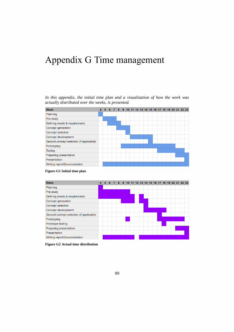
89
Time management
In this appendix, the initial time plan and a visualization of how the work was
actually distributed over the weeks, is presented.
Figure G1 Initial time plan
Figure G2 Actual time distribution