automated teller machine installation manual · pdf filethe triton argo g60 atm is a lobby...
TRANSCRIPT

CORPORATE HEADQUARTERS:
21405 B STREET
LONG BEACH, MS 39560PHONE: (800) 259-6672
FAX: (228) 868-9445
© 2014 Triton. All Rights Reserved. TRITON logo is a registered trademark of Triton Systems of Delaware, LLC.
TDN 07103-00053
AUTOMATED TELLER MACHINEINSTALLATION MANUAL

2
ARGO G60 INSTALLATION MANUAL
DOCUMENT UPDATES
Date Description01/30/14 Original
** WARNING **Do NOT install the mechanism into the unit until the
unit is bolted down to the ground.If the mechanism is installed prior to bolting the unit
down, the unit could tip over and personal injury could occur.
Follow the installation instructions in this manual to ensure the unit is properly installed and secured
BEFORE installing the mechanism.
3
ARGO G60 INSTALLATION MANUAL
The Triton ARGO G60 ATM is a lobby terminal designed for indoor use only. The following sections pro-vide the requirements for installing the ARGO G60 for your particular site location. To assist in preparing your site, a check list is provided of various steps that should be carried out prior to the arrival of the ATM.
CONTENTSPURPOSE / SCOPE / APPLICATION..........................................................................................................................................3
REQUIRED PARTS AND TOOLS .............................................................................................................................................4
SITE COMPLIANCE...............................................................................................................................................4
ENVIRONMENTAL PRECAUTIONS CHECKLIST .............................................................. ..........................................5
TEMPERATURE / POWER / RF INTERFERENCE REQUIREMENTS...................................................................................5
DIMENSIONS .............................................................................................................. ..........................................6CABINET FRONT VIEW / SERVICE AREA DIMENSIONS.............................................................................................7CABINET SIDE VIEWS..........................................................................................................................................8CABINET TOPPER / SIGN AREA.............................................................................................................................9CABINET “FOOTPRINT”......................................................................................................................................10CABINET DECAL AREA.......................................................................................................................................11REPLACING OLDER UNITS...................................................................................................................................12
CABINET INSTALLATION.....................................................................................................................................13 UNPACK ATM ..................................................................................................................................................14MARK/DRILL MOUNTING HOLES.........................................................................................................................15INSTALL STANDARD ANCHORS/BOLT ATM TO FLOOR...........................................................................................16
ROUTE AC POWER AND COMMUNICATION CABLE..............................................................................................17
APPENDIX A - SOFTWARE LICENSE AGREEMENT / COMPLIANCE/EMISSIONS STATEMENTS
APPENDIX B - ATM INSTALLATION FOR ACCESSIBILITY
PURPOSE This guide covers the procedure for installing a Triton ARGO G60 ATM with security, stability and ease of operation in mind.
SCOPE
This procedure applies to all service personnel involved in the process of maintaining, converting, or upgrading hardware and software on Triton ATMs nationwide and abroad.
APPLICATION
This Installation Guide provides information, methods and requirements for the physical installation of the Triton ARGO G60 ATM. It contains site preparation, electrical specifi cations, and cabinet accessibility options that comply with all relevant codes, laws and regulations.
INTRODUCTION

4
ARGO G60 INSTALLATION MANUAL
The site must be prepared by the customer or his agent who is fully conversant with the requirements of installing ATM equipment. The responsibility for ensuring that the site is prepared in compliance with this document remains with the customer. For information and guidance only, a list is provided in general terms of those matters for which the customer is responsible. The list is not intended to be comprehensive and in no way modifi es, alters, or limits the responsibility of the customer for all aspects of adequate site preparation.1. Location of the equipment and site preparation.2. Site wiring (power, communication). Ensure access will not be hindered by cabinet placement.3. Location of other equipment that may cause electrical, electromagnetic or heat induced interference.4. Make building alterations to meet wiring and other site requirements.5. Install all communication cables, wall jacks, and associated hardware.6. Provide and install necessary power distribution boxes, conduits, and grounds.7. Ensure all applicable codes, regulations, and laws (electrical, building, safety) are adhered to.8. Ensure the environmental requirements of this unit are met.9. Install the unit at a height which meets the ADA/DDA/CSA accessibility regulations for the state/country
installed. Refer to Appendix B.
TOOLS REQUIRED Torque wrench adjustable to at least 60 foot pounds, adjustable crescent wrench or ratchet wrench, hammer, 3/4” (19mm) socket, large fl at screwdriver, bubble level, 7/16” socket/box wrench, safety goggles, hearing protection, 1/4” (6mm), 1/2: (12mm) and 9/16” (15mm) carbide-tipped masonry drill bits at least 6” long, 3/4” heavy-duty electric drill (rotaty hammer, back support belt, portable vaccuum cleaner, wire brush.
******NOTE:****** The following kit is required, but not supplied. Call number below for information on availability.
KIT # 06200-00066 Standard anchor kit (four 1/2” x 4 1/2” sleeve-type anchor bolts, 1/2” nuts, 1/2” fl at washers)
SELECTING THEINSTALLATION LOCATION
Choosing the right location for your ATM is very important. Security concerns suggest a location that is away from any door or external access point. Ideally, the terminal should be mounted as close to a back wall as possible. For marketing reasons, however, it may be desirable to locate the terminal near the front where your customers can easily locate it. Wherever you decide to locate the terminal, be sure to follow the recommended procedures for both mounting the terminal and for removing cash when the unit will be unattended.
REQUIRED PARTS AND TOOLS
SITE COMPLIANCE

5
ARGO G60 INSTALLATION MANUAL
SITE PREPARATION CHECKLIST
1. Select site and design fl oor plan accordingly.2. Ensure all environmental conditions are met.3. Establish contractor and vendor schedules.4. Check communication line requirements.5. Plan installation and accessory needs before starting.6. Check fl oor plan and make necessary alterations.7. Install all required electrical fi xtures.8. Prepare site for communications needs.9. Plan operator/training exercises (optional).10. Install communication lines and test.11. Ensure installation accessories are available.
TEMPERATURE / HUMIDITY1. The ATM will operate over a range of
temperatures and humidity. Generally, these parameters must fall within the following ranges:
Temperature • 10°C to 40°C • 50°F to 104°F Relative Humidity • 20% to 80% • (Non-Condensing)
AC POWER REQUIREMENTS2. Ensure the following AC power requirements are met: Power Consumption (Idle)
• 0.6A @ 115 VAC at 60 Hz Power Consumption (Max Load) • 250 Watts @ 120VAC
Current (Max) • 2.2A @ 115 VRMS at 60 Hz Voltage • 90 - 240 VRMS @ 50/60 Hz
ENVIRONMENTAL PRECAUTION CHECKLIST
6
ARGO G60 INSTALLATION MANUAL
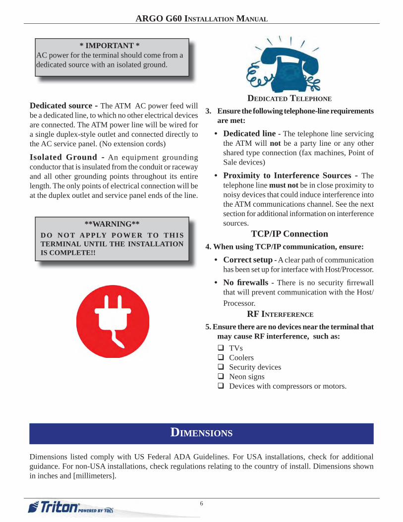
* IMPORTANT *AC power for the terminal should come from a dedicated source with an isolated ground.
Dedicated source - The ATM AC power feed will be a dedicated line, to which no other electrical devices are connected. The ATM power line will be wired for a single duplex-style outlet and connected directly to the AC service panel. (No extension cords)
Isolated Ground - An equipment grounding conductor that is insulated from the conduit or raceway and all other grounding points throughout its entire length. The only points of electrical connection will be at the duplex outlet and service panel ends of the line.
DEDICATED TELEPHONE
3. Ensure the following telephone-line requirements are met:
• Dedicated line - The telephone line servicing the ATM will not be a party line or any other shared type connection (fax machines, Point of Sale devices)
• Proximity to Interference Sources - The telephone line must not be in close proximity to noisy devices that could induce interference into the ATM communications channel. See the next section for additional information on interference sources.
TCP/IP Connection4. When using TCP/IP communication, ensure:
• Correct setup - A clear path of communication has been set up for interface with Host/Processor.
• No fi rewalls - There is no security fi rrewall that will prevent communication with the Host/Processor.
RF INTERFERENCE 5. Ensure there are no devices near the terminal that
may cause RF interference, such as: TVs Coolers Security devices Neon signs Devices with compressors or motors.
**WARNING**DO NOT APPLY POWER TO THIS TERMINAL UNTIL THE INSTALLATION IS COMPLETE!!
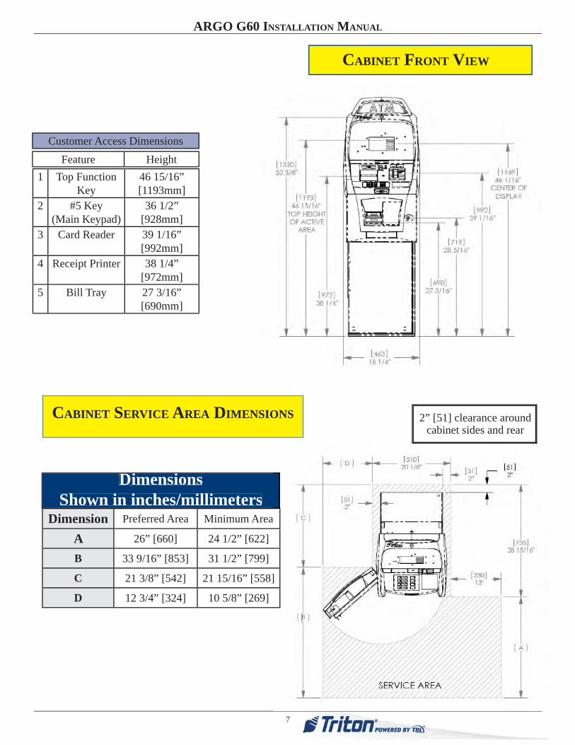
Dimensions listed comply with US Federal ADA Guidelines. For USA installations, check for additional guidance. For non-USA installations, check regulations relating to the country of install. Dimensions shown in inches and [millimeters].
DIMENSIONS
7
ARGO G60 INSTALLATION MANUAL
1 Top Function Key
46 15/16”[1193mm]
2 #5 Key(Main Keypad)
36 1/2”[928mm]
3 Card Reader 39 1/16”[992mm]
4 Receipt Printer 38 1/4”[972mm]
5 Bill Tray 27 3/16”[690mm]
Feature HeightCustomer Access Dimensions
CABINET FRONT VIEW
CABINET SERVICE AREA DIMENSIONS
Dimension Preferred Area Minimum Area
A 26” [660] 24 1/2” [622]
B 33 9/16” [853] 31 1/2” [799]
C 21 3/8” [542] 21 15/16” [558]
D 12 3/4” [324] 10 5/8” [269]
DimensionsShown in inches/millimeters
i i
2” [51] clearance around cabinet sides and rear

8
ARGO G60 INSTALLATION MANUAL
CABINET DIMENSIONS
SIDE VIEWS
Left
Left
Right
Right

9
ARGO G60 INSTALLATION MANUAL
CABINET
TOPPER
CABINET
SIGN AREA
BACKLIT GRAPHIC
RearSideFront

10
ARGO G60 INSTALLATION MANUAL
CABINET
“FOOTPRINT”

11
ARGO G60 INSTALLATION MANUAL
CABINET DECAL AREA
SUGGESTED DECAL AREA
VISIBLE DECAL AREA

12
ARGO G60 INSTALLATION MANUAL
REPLACING OLDER UNITS
When replacing older Triton ATMs with the ARGO G60, you may be able to use holes already drilled to install the ATM. See the table below for corresponding hole sites.
CABINET ARGO G60• 9100 with SDD (deep version)• 9700-9750 (deep version)• RL5000• RL2000 (deep version)
13
ARGO G60 INSTALLATION MANUAL
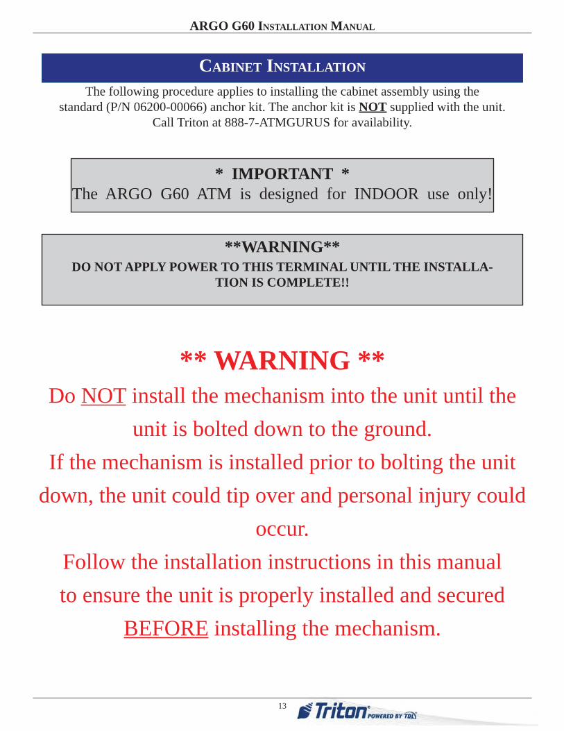
CABINET INSTALLATION
The following procedure applies to installing the cabinet assembly using the standard (P/N 06200-00066) anchor kit. The anchor kit is NOT supplied with the unit.
Call Triton at 888-7-ATMGURUS for availability.
* IMPORTANT *The ARGO G60 ATM is designed for INDOOR use only!
**WARNING**DO NOT APPLY POWER TO THIS TERMINAL UNTIL THE INSTALLA-
TION IS COMPLETE!!
** WARNING **Do NOT install the mechanism into the unit until the
unit is bolted down to the ground.If the mechanism is installed prior to bolting the unit
down, the unit could tip over and personal injury could occur.
Follow the installation instructions in this manual to ensure the unit is properly installed and secured
BEFORE installing the mechanism.
14
ARGO G60 INSTALLATION MANUAL
1. Carefully inspect the shipping container for any damage and report any damage immediately to the shipping company. Refer to the warranty information in the User Manual for information about reporting shipping damage.
2. Remove the ATM cabinet from the carton by cutting the straps and removing the top of the box.
3. Remove the packing material from inside of the box.
4. Remove the silver key from the white plastic bag attached to the ATM wrapping.
5. Remove the remainder of the box from the ATM if necessary.
6. Remove the wrapping from the ATM.
7. Use the silver key to unlock both the control panel and the fascia door (which conceals the locking mechanism) on the front of the cabinet. Open the fascia door.
8. Lift the handle under the bill chute to open the front enclosure door. If the door is locked, see the sidebar on this page for help in unlocking the electronic or mechanical lock, if applicable.
9. Remove the packing material from inside the vault enclosure and the control panel area.
10. The accessory box is shipped inside the cabinet enclosure. Open and inspect the contents. Check the contents against the enclosed packing list and report any missing parts to Triton.
11. Unbolt the ATM from the shipping pallet. Walk the ATM off of the pallet using caution. The ATM is heavy.
UNPACK ATM
Combination LocksMechanical Lock: There are two marks on the dial ring. The index mark at the top of the dial is used for opening the lock. A revolu-tion is counted each time the selected number is aligned with the opening index.
Locks are shipped on a fac-tory setting of ‘50’. To un-lock, turn the dial to the left (counterclockwise) FOUR (4) turns, stopping on ‘50’. Then turn the dial to the right (clockwise) until the bolt is retracted.
Electronic Lock: The com-bination of the lock is preset to 1-2-3-4-5-6. To unlock, enter the preset combination and check for proper opera-tion. After each keypress the lock will ‘beep’. After the fi nal digit has been entered, the lock will beep twice and the open period begins.
When a valid combination has been entered, the opera-tor will have approximately 3 seconds to open the lock. To open the lock, turn the outer ring of the dial to the right (clockwise). After the lock is opened, the vault door may be opened.

15
ARGO G60 INSTALLATION MANUAL
Mark the location of the cabinet mounting holes on the concrete fl oor. This is accomplished as described below:
1. Move the ATM to the location where it will be installed. Open the cabinet vault door at least 90° to improve access. Locate the four (4) anchor-bolt holes in the
bottom of the cabinet (each corner). Use a felt-tip pen or other marker to carefully mark the center of each of the four corner holes on the fl oor; these marks will serve as guides for the anchor bolt holes that will be drilled in the next step. Move the ATM aside to provide clear access to the mounting hole marks. Center punch each mark to help align the drill bit.
2. Use a 1/4” [6 mm] diameter carbide-tipped masonry bit to drill four pilot holes at the drilling points marked in the previous step. Drill the pilot holes approximately 1/2” [12 mm] deep into the fl oor. These holes will help guide the masonry bit that will be used to drill the anchor-bolt holes in the next step.
Mark/Drill Mounting Holes
5. Use a portable vacuum cleaner to remove any dust or debris that may have fallen into the holes during the drilling process.
4. Hole Diameter: Ensure the holes drilled are not too large in diameter. Test fi t the anchor bolts by hand. They should require hammering, NOT NOW, and not fall into the hole. Its easier to drill the holes larger now if necessary, than have to move the cabinet and redrill later because they are too big. DO NOT be tempted to install the anchors now. It is VERY diffi cult to position the terminal onto the anchors because of the weight.
3. Standard anchors: Use a 1/2” [13mm] diameter carbide-tipped masonry bit to drill four holes at least 2-3/4” [70mm] deep into the fl oor. Be sure to take into account the depth of any fl oor covering, such as tile or vinyl when gauging the depth of the anchor holes. Make sure the holes are drilled at least 2- 3/4” [70mm] into the concrete fl oor. (See Install Standard Anchors/Bolt ATM to Floor on next page.)

16
ARGO G60 INSTALLATION MANUAL
INSTALL STANDARD ANCHORS/BOLT ATM TO FLOOR
LOCKING NUT
FLAT WASHER
ARGO ATM BASE
ANCHOR BOLT
MOUNTING NUT
Anchor bolt installation illustration
SLAB
Anchor Bolt
1. Ensure the mounting location is free of all debris that might cause the cabinet to not be level. Use blower or vaccuum to remove any dust or particles.
2. Move the ATM into position for mounting by aligning the base over the four holes drilled in the previous procedure.
3. Place an anchor bolt through the cabinet base and into one of the
mounting holes. Use a ball peen hammer to tap the bolt completely into the hole.
IMPORTANT: If the anchor bolt “falls” into the hole without being tapped in, the hole is too large! Move the mounting hole pattern and redrill using smaller holes as necessary to achieve a snug fi t.
4. Place a fl at washer on the anchor bolt followed by a 1/2” (13mm) nut. Do not tighten fully, allow for leveling.
5. Repeat Steps 3 and 4 for the remaining anchor bolts.
17
ARGO G60 INSTALLATION MANUAL
6. Ensure the cabinet is as level as possible given the fl oor conditions. Use a bubble level to verify this. If a bubble-level is not available, the cabinet can be “rocked” gently from front-to-back and side-to-side to check the need for leveling.
7. Use a torque wrench and 3/4” [19mm] socket to tighten each nut to 60 foot-pounds (required to establish the maximum pull-out strength of the anchors). If a torque wrench is not available, use a ratchet wrench and 3/4” [19mm] socket to tighten the nuts three full turns beyond hand tight. DO NOT overtighten.
8. Once the nuts are tightened as specifi ed in Step 7, install a second nut on each bolt, to act as a jam nut, and tighten down fi rmly.
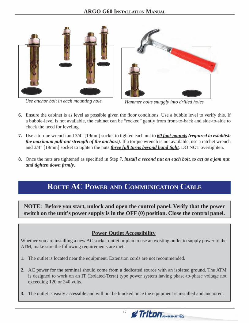
Use anchor bolt in each mounting hole Hammer bolts snuggly into drilled holes
NOTE: Before you start, unlock and open the control panel. Verify that the power switch on the unit’s power supply is in the OFF (0) position. Close the control panel.
Power Outlet AccessibilityWhether you are installing a new AC socket outlet or plan to use an existing outlet to supply power to the ATM, make sure the following requirements are met:
1. The outlet is located near the equipment. Extension cords are not recommended.
2. AC power for the terminal should come from a dedicated source with an isolated ground. The ATM is designed to work on an IT (Isolated-Terra) type power system having phase-to-phase voltage not exceeding 120 or 240 volts.
3. The outlet is easily accessible and will not be blocked once the equipment is installed and anchored.
ROUTE AC POWER AND COMMUNICATION CABLE

18
ARGO G60 INSTALLATION MANUAL
1. Route the AC power cord and the phone (or Cat-5) cable through either the main or alternate cable access hole at rear corner of unit (as applicable).
2. Connect the AC power cord and communication cable to their respective facility outlets.
3. Secure/plug the unused access hole with the grommet or plug provided.
4. Install the security bracket. This new feature introduced with the ARGO G60 prevents both people and rodents from accessing the dispenser and internal wiring through the holes at the bottom of the cabinet. The bracket and four (4) nuts are found packaged in the accessory bag that is shipped with the ARGO G60.
Fit the bracket on the fi xed bolts, then use an 11/32” driver to tighten the nuts.
This unit may be equipped with more than one power cord. Disconnect All Power Cords prior to Servicing!
For continued fault protection, follow the correct voltage and current ratings when replacing any fuses.
Route wiring and communication harnesses through openings in bottom rear of cabinet and to power supply.
The ARGO G60 unit has an additonal security feature with the additon of a special bracket between the upper and lower cabinets to secure cables and wiring running between the cabinets. This is already installed on the ARGO G60 from the factory. One must have access to both the upper and lower cabinets in order to add or remove cables/wiring. The bracket has a top screw and three fi xed bolts underneath. Unscrew the screw and three nuts to release the bracket.
Attach security bracket to lower left corner of cablinet as shown.
19
ARGO G60 INSTALLATION MANUAL
POWER SUPPLY CORDSPECIFICATIONS
For European applications, the power supply cord must conform to the following:
1. Two-conductor with Physical Earth (PE) ground.
2. IEC 320 molded connector on one end and molded plug on the other end.
3. Certifi ed for country of installation.
4. Rated minimum H05VV-F with minimum 0.75 mm2 (except where specifi c countries require 1.0 mm2) conductors.
5. Maximum length: 3 meters.
REFER TO THE USER MANUAL AND CONFIGURATION MANUAL FOR OPERATIONAL INSTRUCTIONS.
NOTE: IT MAY TAKE UP TO 30 SECONDS FOR THE DISPLAY TO ILLUMINATE, AND ANOTHER 15 SECONDS FOR THE OPERATING SYSTEM TO LOAD.

APPENDIX ASOFTWARE LICENSE AGREEMENT
COMPLIANCE / EMISSION STATEMENTS

A-2
APPENDIX A - SOFTWARE LICENSE AGREEMENT / COMPLIANCE/EMISSION STATEMENTS
AUTOMATED TELLER MACHINE (“ATM”) SOFTWARE
END-USER AGREEMENT
IMPORTANT: PLEASE READ CAREFULLY:
BY INSTALLING OR OTHERWISE USING THE ATM, YOU (AS THE OWNER OR LESSEE OF THE ATM).AGREE TO BE BOUND BY THE FOLLOWING TERMS AND CONDITIONS, INCLUDING, WITHOUTLIMITATION, THE WARRANTY DISCLAIMERS, LIMITATIONS OF LIABILITY AND TERMINATIONPROVISION WHICH APPLY TO YOUR USE OF THE ATM SOFTWARE CONTAINED IN THIS ATM ANDIS HEREBY LICENSED BY TRITON SYSTEMS OF DELAWARE, INC. (“Triton”) TO YOU PURSUANT TOTHIS AGREEMENT.
IF YOU DO NOT AGREE TO OR ARE NOT WILLING TO BE BOUND BY THE TERMS AND CONDITIONSOF THIS AGREEMENT, DO NOT INSTALL OR OTHERWISE USE THIS ATM AND PROMPTLY CON-TACT YOUR VENDOR. INSTALLING OR OTHERWISE USING THE ATM INDICATES THAT YOU AC-CEPT THESE TERMS.
This ATM is manufactured by, and utilizes proprietary software owned by Triton Systems of Delaware, Inc.and/or its suppliers. All right, title and interest in and to all component software installed or embedded inthe ATM (“ATM Software”) including all associated intellectual property rights, are and will remain theproperty of Triton and/or its suppliers.
LICENSE: Triton grants you a limited, nonexclusive license to use the ATM Software but only in connec-tion with the operation of this ATM subject to the terms and restrictions set forth in this License Agreement.You are not permitted to use the ATM Software in any manner not expressly authorized by this License. Youacknowledge and agree that ownership of the ATM Software and all subsequent copies thereof regardlessof the form or media are held by Triton or its suppliers.
The software is licensed for use on this specific Triton ATM product and may not be used on any otherproduct. Otherwise, the supporting documentation, if any, may be copied only as essential for backup orarchive purposes in support of your use of the ATM. You must reproduce and include all copyright noticesand any other proprietary rights notices appearing on any copies that you make.
ASSIGNMENT: NO REVERSE ENGINEERING: You may transfer the ATM Software to another party butonly in connection with a transfer of all your right, title and interest in and to this ATM and if such partyaccepts the terms and conditions of this License Agreement. If you transfer the ATM, you must at the sametime transfer the supporting documentation, if any, to the same party or destroy any such materials nottransferred. Modification, reverse engineering, reverse compiling, or disassembly of the ATM and/or theATM Software is expressly prohibited.

A-3
APPENDIX A - SOFTWARE LICENSE AGREEMENT / COMPLIANCE/EMISSION STATEMENTS
DISCLAIMER OF WARRANTIES AND LIMITATION OF DAMAGES
TO THE EXTENT PERMITTED BY LAW, THIS ATM SOFTWARE, INCLUDING ALL INCORPORATEDTHIRD PARTY SOFTWARE, AND DERIVATIVES IS PROVIDED, “AS IS”. TRITON MAKES NO REPRE-SENTATIONS WITH RESPECT TO, AND DOES NOT WARRANT THE PERFORMANCE OR RESULTSYOU OR YOUR CUSTOMERS MAY OBTAIN BY USING THE ATM. TRITON SPECIFICALLY DISCLAIMSANY AND ALL WARRANTIES, EXPRESS, IMPLIED OR STATUTORY, INCLUDING WITHOUT LIMITA-TION, WARRANTIES OF QUALITY, PERFORMANCE, NONINFRINGEMENT, AND MERCHANTABIL-ITY OR FITNESS FOR ANY PARTICULAR PURPOSE.
TRITON MAKES NO REPRESENTATIONS OR WARRANTIES AND ASSUMES NO OBLIGATIONS TOYOU OR YOUR CUSTOMERS WITH RESPECT TO ANY TRANSACTION OR SERVICES ACCESSEDAND/OR UTILIZED IN CONSUMER-INITIATED TRANSACTIONS MADE FROM THIS ATM. IN NOEVENT WILL TRITON, ITS AFFILIATES, DIRECTORS, OFFICERS, EMPLOYEES, AGENTS OR SUPPLI-ERS BE LIABLE TO YOU UNDER ANY THEORY OF TORT, CONTRACT, STRICT LIABILITY OR OTHERLEGAL OR EQUITABLE THEORY FOR ANY PUNITIVE, CONSEQUENTIAL, INCIDENTAL, SPECIAL ORSIMILAR DAMAGES, INCLUDING ANY LOSS PROFITS OR LOST SAVINGS, EVEN IF A TRITON AGENTOR REPRESENTATIVE HAS BEEN ADVISED OF THE POSSIBILITY OF SUCH DAMAGES, OR FOR ANYCLAIM BY ANY THIRD PARTY.
YOUR SOLE REMEDY AGAINST TRITON FOR DEFECTIVE PERFORMANCE OF THE ATM SOFTWAREWILL BE LIMITED EXCLUSIVELY TO REPAIR OR REPLACEMENT OF THE ATM AND/OR THE ATMSOFTWARE, AT TRITON’S SOLE DISCRETION.
Any warranty pertaining to the ATM, its mechanical components exclusive of the ATM software, shall begoverned and controlled by any warranty given to you by Triton in a separate document accompanyingthis ATM.
The foregoing limitation of liability and exclusion of certain damages will apply regardless of the success oreffectiveness of other remedies.
GOVERNING LAW: This License Agreement shall be governed by the laws of the State of Mississippi andby the laws of the United States, excluding their conflicts of laws principles.
SEVERABILITY: In the event any provision of this License Agreement is found to be invalid, illegal orunenforceable, the validity, legality and enforceability of any of the remaining provisions shall not in anyway be affected or impaired.
ENTIRE AGREEMENT: This License Agreement and the accompanying Limited Warranty set forth theentire agreement between you and Triton, supersedes all prior agreements, whether written or oral, withrespect to the ATM Software, and may be amended only in writing signed by both parties.

A-4
APPENDIX A - SOFTWARE LICENSE AGREEMENT / COMPLIANCE/EMISSION STATEMENTS
COMPLIANCE / EMISSION STATEMENTS
DISCLAIMERThe manufacturer of the Automated Teller Machine (ATM) product(s) described herein makes norepresentations or warranties, either expressed or implied, by or with respect to anything in this manual, andshall not be liable for any implied warranties of fitness for a particular purpose or for any indirect, special, orconsequential damages. Information in this document is subject to change without notice and does notrepresent a commitment on the part of the manufacturer.
EMISSIONS (EMI)(US Requirements)
This device complies with Part 15 of the FCC rules.Operation is subject to the following two (2)conditions:1) This device may not cause harmful interference.2) This device must accept any interference received,including interference that may cause undesiredoperation.
NOTE:This equipment has been tested and found to comply with the limits for a Class A digital device pursuant toPart 15 of FCC rules. These limits are designed to provide reasonable protection against harmful interferencewhen the equipment is operated in a commercial environment. This equipment generates, uses, and canradiate radio frequency energy and, if not installed and used in accordance with the instruction manual, maycause harmful interference to radio communications. Operation of this equipment in a residential area islikely to cause harmful interference in which case the user will be required to correct the interference at hisown expense. Changes or modifications to this unit not expressly approved by the party responsible forcompliance could void the user’s authority to operate the equipment.
CANADIAN REQUIREMENTS
This digital apparatus does not exceed the Class A limits for radio noise emissions from digital apparatus setin the Radio Interference Regulations of the Canadian Department of Communications. This Class A digitalapparatus complies with Canadian ICES-003.
UK / AUSTRALIA / SOUTH AFRICA REQUIREMENTSWarning:
This is a Class A product. In a domestic environment, this product may cause radio interference in whichcase the user may be required to take adequate measures.
Le present appareil numerique n’emet pas de bruits radioelectriques depassant les limites applicables auxappareils numeriques de la Class A prescrites dans le Reglement sur le brouillage radioelectrique edicte parle ministere des Communications du Canada. Cet appareil numerique de la classe A est conforme a la normeNMB-003 Canada.
** CAUTION **
Changes or modifications not expressly approvedby Triton Systems could void the regulatorycompliance approval and the warranty. Use of thisproduct in a manner other than those described inthis manual may result in personal injury!
Appendix BATM insTAllATion for AccessiBiliTy

Appendix B - ATM insTAllATion for AccessiBiliTy
B-2
A Guide to the ADA Guidelines
305. Clear Floor or Ground Space
305.1 General. Clear floor or ground space shall comply with 305.
305.2 Floor or Ground Surfaces. Floor or ground surfaces of a clear floor or ground space shall comply with 302. Changes in level are not permitted.
EXCEPTION: Slopes not steeper than 1:48 shall be permitted.
305.3 Size. The clear floor or ground space shall be 30 inches (760 mm) minimum by 48 inches (1220 mm) minimum. Figure 305.3 Clear Floor or Ground Space
305.4 Knee and Toe Clearance. Unless otherwise specified, clear floor or ground space shall be permitted to include knee and toe clearance complying with 306.
305.5 Position. Unless otherwise specified, clear floor or ground space shall be positioned for either forward or parallel approach to an element.
305.6 Approach. One full unobstructed side of the clear floor or ground space shall adjoin an accessible route or adjoin another clear floor or ground space.
305.7 Maneuvering Clearance. Where a clear floor or ground space is located in an alcove or otherwise confined on all or part of three sides, additional maneuvering clearance shall be provided in accordance with 305.7.1 and 305.7.2.
305.7.1 Forward Approach. Alcoves shall be 36 inches (915 mm) wide minimum where the depth exceeds 24 inches (610 mm). 305.7.2 Parallel Approach. Alcoves shall be 60 inches (1525 mm) wide minimum where the depth exceeds 15 inches (380 mm).
Figure 305.7.1 Maneuvering Clearance in an Alcove, Forward Approach
Figure 305.7.2 Maneuvering Clearance in an Al-cove, Parallel Approach
Figure 305.5 Position of Clear Floor or Ground Space

B-3
Appendix B - ATM insTAllATion for AccessiBiliTy
308. Reach Ranges
308.1 General. Reach ranges shall comply with 308.
308.2 Forward Reach.
308.2.1 Unobstructed. Where a forward reach is unobstructed, the high forward reach shall be 48 inches (1220 mm) maximum and the low forward reach shall be 15 inches (380 mm) minimum above the finish floor or ground.
Figure 308.2.1 Unobstructed Forward Reach
308.2.2 Obstructed High Reach. Where a high forward reach is over an obstruction, the clear floor space shall extend beneath the element for a distance not less than the required reach depth over the obstruction. The high forward reach shall be 48 inches (1220 mm) maximum where the reach depth is 20 inches (510 mm) maximum. Where the reach depth exceeds 20 inches (510 mm), the high forward reach shall be 44 inches (1120 mm) maximum and the reach depth shall be 25 inches (635 mm) maximum.
Figure 308.2.2 Obstructed High Forward Reach
308.3 Side Reach.
308.3.1 Unobstructed. Where a clear floor or ground space allows a parallel approach to an element and the side reach is unobstructed, the high side reach shall be 48 inches (1220 mm) maximum and the low side reach shall be 15 inches (380 mm) minimum above the finish floor or ground.
Figure 308.3.1 Unobstructed Side Reach
EXCEPTIONS:
1. An obstruction shall be permitted between the clear floor or ground space and the element where the depth of the obstruction is 10 inches (255 mm) maximum.
2. Operable parts of fuel dispensers shall be permitted to be 54 inches (1370 mm) maximum measured from the surface of the vehicular way where fuel dispensers are installed on existing curbs.

Appendix B - ATM insTAllATion for AccessiBiliTy
B-4
308.3.2 Obstructed High Reach. Where a clear floor or ground space allows a parallel approach to an element and the high side reach is over an obstruction, the height of the obstruction shall be 34 inches (865 mm) maximum and the depth of the obstruction shall be 24 inches (610 mm) maximum. The high side reach shall be 48 inches (1220 mm) maximum for a reach depth of 10 inches (255 mm) maximum. Where the reach depth exceeds 10 inches (255 mm), the high side reach shall be 46 inches (1170 mm) maximum for a reach depth of 24 inches (610 mm) maximum.
EXCEPTIONS:
1. The top of washing machines and clothes dryers shall be permitted to be 36 inches (915 mm) maximum above the finish floor.
2. Operable parts of fuel dispensers shall be permitted to be 54 inches (1370 mm) maximum measured from the surface of the vehicular way where fuel dispensers are installed on existing curbs.
Figure 308.3.2 Obstructed High Side Reach
ATM insTAllATion for AccessiBiliTy
1. This document supersedes all other information provided by Triton for ATM installation for accessibility.
2. Information provided in this manual is based on federal guidelines (ADA Accessibility Guidelines for Buildings and Facilities – ADAAG) as amended through January 1998. You should verify it has not been amended. States may also have accessibility codes. These codes may be more restrictive than the federal guidelines. Please verify this with the state where the ATM is to be installed prior to installation. For state contact information, you may call the ADA information line at 1-800-514-0301.
3. For countries other than the US, please use the guidelines for accessibility for that country.
4. A complete copy of the ADAAG referred to here can be found at http://www.access-board.gov. Included in this document is the section of the ADAAG specifically for ATMs. For additional information on floor surfaces and other ADAAG requirements, please see the complete specification.
4.34 Automated Teller Machines. 4.34.1 General. Each automated teller machine machine required to be accessible by 4.1.3 (Accessible Buildings: New
Construction) shall be on an accessible route and shall comply with 4.34 (Automated Teller Machines).
4.34.2 Clear Floor Space. The automated teller machine shall be located so that clear floor space complying with 4.2.4 (Clear Floor or Ground Space for Wheelchairs) is provided to allow a person using a wheelchair to make a forward approach, a parallel approach, or both to the machine.
4.34.3 Reach Ranges.
(1) Forward Approach Only. If only a forward approach is possible, operable parts of all controls shall be placed within the forward reach range specified in 4.2.5 (Forward Reach).
(2) Parallel Approach Only. If only a parallel approach is possible, operable parts of controls shall be placed as follows:

B-5
Appendix B - ATM insTAllATion for AccessiBiliTy
(a) Reach Depth Not More Than 10 inches (255 mm). Where the reach depth to the operable parts of all controls as measured from the vertical plane perpendicular to the edge of the unobstructed clear floor space at the farthest protrusion of the automated teller machine or surround is not more than 10 inches (255 mm), the maximum height above the finished floor or grade shall be 54 inches (1370 mm).
b) Reach Depth More Than 10 inches (255 mm). Where the reach depth to the operable parts of any control as measured from the vertical plane perpendicular to the edge of the unobstructed clear floor space at the farthest protrusion of the automated teller machine or surround is more than 10 inches (255 mm), the maximum height above the finished floor or grade shall be as follows:
ACCESSIBILITY SPECIFICATIONS
REACH DEPTH MAXIMUM HEIGHT
Inches Millimeters Inches Millimeters
10 255 54 1370
11 280 53 1/2 1360
12 305 53 1345
13 330 52 1/2 1335
14 355 51 1/2 1310
15 380 51 1295
16 405 50 1/2 1285
17 430 50 1270
18 455 49 1/2 1255
19 485 49 1245
20 510 48 1/2 1230
21 535 47 1/2 1205
22 560 47 1195
23 585 46 1/2 1180
24 610 46 1170
(3) Forward and Parallel Approach. If both a forward and parallel approach are possible, operable parts of controls shall be placed within at least one of the reach ranges in paragraphs (1) or (2) of this section.
4) Bins. Where bins are provided for envelopes, waste paper, or other purposes, at least one of each type provided shall comply with the applicable reach ranges in paragraph (1), (2), or (3) of this section.
EXCEPTION: Where a function can be performed in a substantially equivalent manner by using an alternate control, only one of the controls needed to perform that function is required to comply with this section. If the controls are identified by tactile markings, such markings shall be provided on both controls.
4.34.4 Controls. Controls for user activation shall comply with 4.27.4 (Operation).
4.34.5 Equipment for Persons with Vision Impairments. Instructions and all information for use shall be made accessible to and independently usable by persons with vision impairments.
(20) Where automated teller machines (ATMs) are provided, each ATM shall comply with the requirements of 4.34 (Automated Teller Machines) except where two or more are provided at a location, then only one must comply.
EXCEPTION: Drive-up-only automated teller machines are not required to comply with 4.27 (Controls and Operating Mecha-nisms) and 4.34.3 (Reach Ranges).

Appendix B - ATM insTAllATion for AccessiBiliTy
B-6
4.2.4 Clear Floor or Ground Space for Wheelchairs.
4.2.4.1 Size and Approach. The minimum clear floor or ground space required to accommodate a single, stationary wheelchair and occupant is 30 inches by 48 inches (760 mm by 1220 mm) (see Fig.4a). The minimum clear floor or ground space for wheelchairs may be positioned for forward or parallel approach to an object (see Fig. 4b and 4c). Clear floor or ground space for wheelchairs may be part of the knee space required under some objects.
4.2.4.2 Relationship of Maneuvering Clearance to Wheelchair Spaces. One full unobstructed side of the clear floor or ground space for a wheelchair shall adjoin or overlap an accessible route or adjoin another wheelchair clear floor space. If a clear floor space is located in an alcove or otherwise confined on all or part of three sides, additional maneuvering clearances shall be provided as shown in Fig. 4(d) and 4(e).
Figure 4a. Clear floor space.
Figure 4b. Forward approach.
Figures 4d. Clear Floor Space in Alcoves. Figures 4e. Clear Floor Space in Alcove.
For a front approach, where the depth of the alcove is equal to or less than 24 inches (610 mm), the required clear floor space is 30 inches by 48 inches (760 mm by 1220 mm).
For a front approach, if the depth of the alcove is greater than 24 inches (610 mm), then in addition to the 30-inch (760 mm) width, a maneuvering clearance of 6 inches (150 mm) in width is required.
Figure 4c. Parallel approach.

B-7
Appendix B - ATM insTAllATion for AccessiBiliTy
For a side approach, where the depth of the alcove is equal to or less than 15 inches (380 mm), the required clear floor space is 30 inches by 48 inches (760 mm by 1220 mm).
For a side approach, where the depth of the alcove is greater than 15 inches (380 mm), then in addition to the 48-inch (1220 mm) length, an additional maneuvering clearance of 12 inches (350 mm) is required.
Figures 4d. Clear Floor Space in Alcoves.
4.2.4.3 Surfaces for Wheelchair Spaces. Clear floor or ground spaces for wheelchairs shall comply with 4.5 (Ground and Floor Surfaces).
4.2.5 Forward Reach. If the clear floor space only allows forward approach to an object, the maximum high forward reach allowed shall be 48 inches (1220 mm) (see Fig. 5(a)). The minimum low forward reach is 15 inches (380 mm). If the high forward reach is over an obstruction, reach and clearances shall be as shown in Fig. 5(b).
Figures 4e. Clear Floor Space in Alcove.
Figure 5a. Forward reach, unobstructed.
Figure 5b. Forward reach, obstructed.

Appendix B - ATM insTAllATion for AccessiBiliTy
B-8
4.2.6 Side Reach. If the clear floor space allows parallel approach by a person in a wheelchair, the maximum high side reach allowed shall be 54 inches (1370 mm) and the low side reach shall be no less than 9 inches (230 mm) above the floor (Fig. 6(a) and 6(b)). If the side reach is over an obstruction, the reach and clearances shall be as shown in Fig 6(c).
Figure 6a. Parallel approach - side reach.
Figure 6b. Parallel approach - high/low side reach.
Figure 6c. Side reach, obstructed.
Outside Handicap Access Area
48"(1219 mm)- Across -
30"(762 mm)- Deep -
* Measuredfrom center ofControl Panel
Fascia *
Figure 7. ADA access dimensions for Walk-up/Drive-up ATM.