automated, motorized, chromatic string- tuning device · pdf fileautomated, motorized,...
TRANSCRIPT

1
Automated, Motorized, Chromatic String-
Tuning Device
Matthew Arbesfeld
Benjamin Edelstein
Lexington High School
November 2010 – May 2011
2
Abstract
The goal of this project was to design and build a compact and inexpensive device which
could automatically analyze the pitch of an instrument’s string and adjust the string’s tension to
achieve a desired frequency of vibration. Many musicians find the process of tuning their
instruments difficult and time-consuming—the combination of auditory and physical elements
is hard to master for both beginners and advanced players. While existing models of electronic
tuners simply display whether a string is sharp or flat compared to a reference frequency, our
model also automatically adjusts the mechanical tuners on an instrument using a high-torque
motor. Thus, a user does not have to manually tune his or her instrument; rather, our device
handles both the aural and mechanical aspects of tuning.
The final prototype of our design consists of a Korg CA-40 chromatic tuner which
analyzes the frequency of a vibrating string and sends an output signal of either sharp or flat to
a L293D four-channel h-bridge which determines the polarity of power routed to a gearhead
motor. This high torque, low rpm motor (7500 g.cm torque, 24 rpm) can be coupled with
attachments that mate with various types of instrument tuning heads, including guitar, cello,
violin, harp and mandolin. A hand-held unit housing both the gearhead motor and the
activation button connects to the main chassis via a CAT-5 cable. The green or “correct” output
from the chromatic tuner, which is enabled when the desired frequency of the string is
reached, is fed into an Arduino UNO microcontroller. Upon the depression of a user-controlled
button, the Arduino begins monitoring the status of the green LED and activates a buzzer when
the string reaches a desired frequency. Lastly, a printed circuit board was designed to unify all
of the device’s processes, including activation of the tuner, operation of the motor, input from
the end user, and output in the form of LED’s and a buzzer.
We envision that our device could revolutionize the way that people tune their
instruments and bring a new level of precise intonation to the music of beginners and
professionals alike.

3
1 Purpose
To design and construct a device which can automatically analyze the pitch of an instrument’s
string and adjust the string’s tension to meet a desired frequency.
2 Introduction
Tuning string instruments, especially those of the orchestral variety, is a difficult and time-
consuming task that can be daunting to both beginners and advanced players. Manual tuning
involves listening to a target note and adjusting one’s own string in the appropriate manner
(either by increasing or decreasing tension). Our automated string-tuning device would not only
eliminate the listening and analyzing elements of the tuning process (as such a device already
exists), it would also automatically adjust the string tension based on examination of the
string’s harmonic frequency.
3 Engineering Goals
Compact and handheld
Inexpensive
Can analyze string frequency to the nearest Hz and precisely adjust motor
Detachable motor head for use with multiple types of instruments
Output various color LED’s based on string frequency
Output signal when string is desired tension
4 Materials and Resources
Solderless breadboard
Korg CA-40 chromatic tuner
Planet Waves CT-01 chromatic tuner
Matrix SR-1050 chromatic tuner
Intelli IMT-301 tuner/metronome
4
Arduino UNO microcontroller
Arduino software
220Ω resistors
17KΩ resistors
10 uF capacitors
Digital multimeter
9v battery holder
6v battery holder
3v battery holder
LEGO Mindstorms 71427 9v motor (250
rpm, 230g.cm)
12v, 24rpm, 7500g.cm Jameco Reliapro
motor
12v, 30rpm, 6400g.cm Jameco Reliapro
motor
L293D half-bridge
Push-button switch
Variable-voltage power supply
Custom-designed printed circuit board
ON-OFF-ON toggle switch
Rocker switch
Soldering iron
Solder
Solder-sucker
Wire strippers
Stranded and solid core wire of various
gauges
5v coil voltage relay
Surface mount toggle switch
Illuminated surface mount rocker
switch
3v surface mount LED’s with leads
5v surface mount LED
3v voltage regulator
ABS plastic enclosure
5v buzzer
¼” surface mount 3-contact jack
Ethernet male/female jack
PVC pipe and caps
Hot glue gun and hot glue
Guitar tuner-head
Machine screws/bolts
Helping hands
Alligator clips
AA batteries
9v batteries
Jeweler’s screwdrivers
Drill press
Band saw
Vice
Pliers
Eagle PCB
Viewplot
Autodesk 3ds Max
Services of Advanced Circuits for PCB
fabrication
5
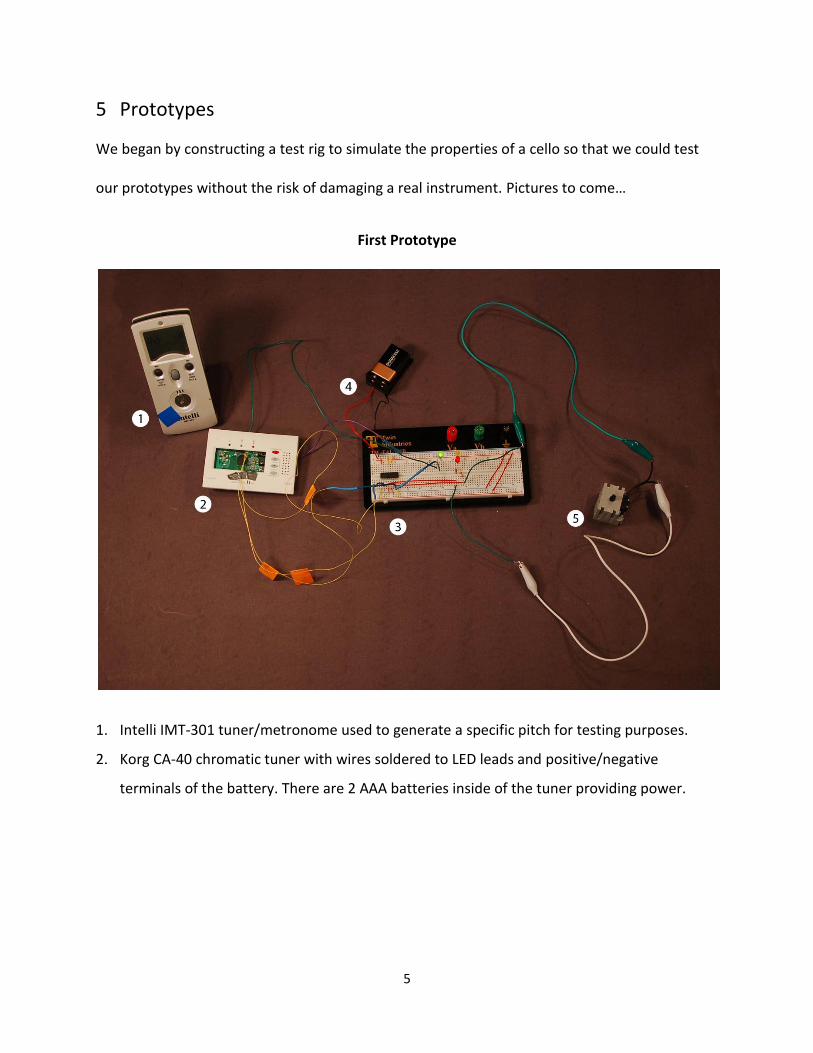
5 Prototypes
We began by constructing a test rig to simulate the properties of a cello so that we could test
our prototypes without the risk of damaging a real instrument. Pictures to come…
First Prototype
1. Intelli IMT-301 tuner/metronome used to generate a specific pitch for testing purposes.
2. Korg CA-40 chromatic tuner with wires soldered to LED leads and positive/negative
terminals of the battery. There are 2 AAA batteries inside of the tuner providing power.

6
3. Breadboard closeup:
L293D chip on solderless breadboard. Sharp and flat outputs are wired into pin 2 and pin 7
respectively on the chip. The motor (5) is connected to pins 3 and 6. Pin 4, 5, 12 and 13
ground the chip to the 9v battery (4) which is connected to both power rails. Pin 9 provides
voltage to power the logic of the chip while pin 8 provides voltage to power the motor.
Thus, while the LED inputs are only ~3.3v, the motor is powered by a 9v battery. In addition
to driving the motor, pins 3 and 6 also output to LED’s through 220Ω resistors. Finally, the
green LED’s high side is connected to the positive end of the battery while its low side is
connected to the green output of the Korg CA-40. (This is due to the circuitry of the tuner.
In the tuner, one side of the LED is constantly connected to 3v while the microcontroller
determines whether the opposite side is 3v or 0v. Therefore, the LED is “on” when the
microcontroller sends 0v while “off” when it sends 3v)
4. 9v battery
5. LEGO Mindstorms 71427 9v motor (250 rpm, 230g.cm)
Pros:
Simple operation
Accurate
Simple circuitry
Cons:
Low torque motor
No on/off switches
7
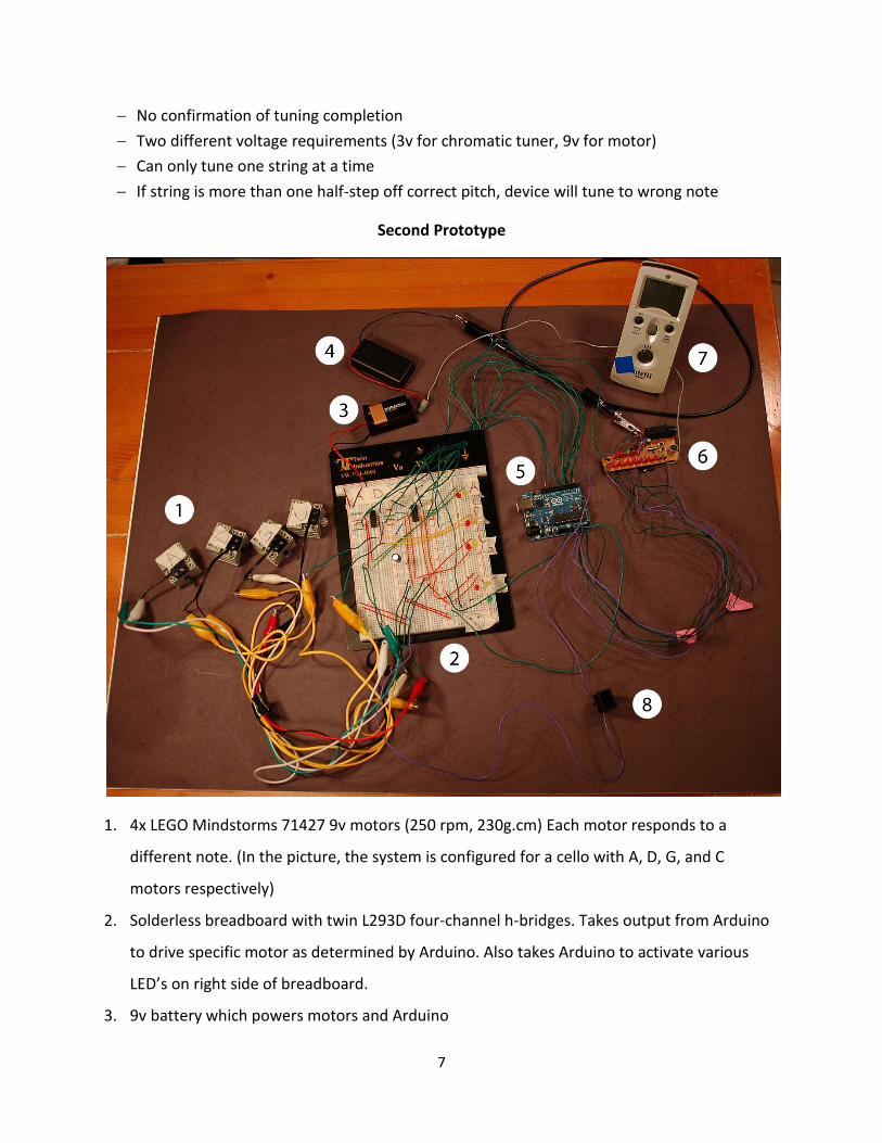
No confirmation of tuning completion
Two different voltage requirements (3v for chromatic tuner, 9v for motor)
Can only tune one string at a time
If string is more than one half-step off correct pitch, device will tune to wrong note
Second Prototype
1. 4x LEGO Mindstorms 71427 9v motors (250 rpm, 230g.cm) Each motor responds to a
different note. (In the picture, the system is configured for a cello with A, D, G, and C
motors respectively)
2. Solderless breadboard with twin L293D four-channel h-bridges. Takes output from Arduino
to drive specific motor as determined by Arduino. Also takes Arduino to activate various
LED’s on right side of breadboard.
3. 9v battery which powers motors and Arduino
8
4. 3v battery (2xAA) which powers Matrix SR-1050 chromatic tuner (6).
5. Arduino which takes outputs from Matrix SR-1050 chromatic tuner to first determine which
motor to turn and then create a high/low signal to power the motor based on desired
frequency. (see program Multiple_Tuner_v3 for full code)
6. Matrix SR-1050 chromatic tuner with wire leads.
7. Intelli IMT-301 tuner/metronome used to generate a specific pitch for testing purposes.
8. Rocker switch used to control power to entire system.
Pros:
Able to control multiple strings
Provides potential for a device that could tune instrument without any human control
Sharp/flat indicators for each string
On/off switch
Cons:
Low torque motor
No confirmation of tuning completion
Two different voltage requirements (3v for chromatic tuner, 9v for motor)
Extremely bulky
Would be difficult to implement in an inexpensive and compact manner
If string is more than one half-step off correct pitch, device will tune to wrong note
/*
Program Multiple_Tuner_v3
Program reads input from LED's connected
to analog A0 - A6 and produces a motor signal to
four different motors. Output is in the form of alternate
high/low signals to be analyzed by h-bridge
Creators:
Matthew Arbesfeld
Benjamin Edelstein
December 15, 2010
*/
//digital output pins; two wires are used for each motor
//so that high-low signal can turn motor one way while
//low-high signal turns motor opposite way
const int buttonPin = 1;

9
const int THRESHOLD = 300;
const int motor_A1 = 2;
const int motor_A2 = 3;
const int motor_D1 = 4;
const int motor_D2 = 5;
const int motor_G1 = 6;
const int motor_G2 = 7;
const int motor_C1 = 8;
const int motor_C2 = 9;
//initialize variable (calculated based on analog inputs)
int sharp = 0;
int flat = 0;
int string_A = 0;
int string_D = 0;
int string_G = 0;
int string_C = 0;
int buttonState = 0;
//function designed to output information to
//serial for debugging purposes
void printInfo()
Serial.print("Sharp: ");
Serial.print(sharp);
Serial.print(" Flat: ");
Serial.println(flat, DEC);
Serial.print("A: ");
Serial.print(string_A);
Serial.print(" D: ");
Serial.print(string_D);
Serial.print(" G: ");
Serial.print(string_G);
Serial.print(" C: ");
Serial.println(string_C, DEC);
return; //return to main loop
//reset all motors to default low state
void resetMotors()
digitalWrite(motor_A1, LOW);
digitalWrite(motor_A2, LOW);
digitalWrite(motor_D1, LOW);
digitalWrite(motor_D2, LOW);
digitalWrite(motor_G1, LOW);
digitalWrite(motor_G2, LOW);
digitalWrite(motor_C1, LOW);
digitalWrite(motor_C2, LOW);
10
return; //return to main loop
void setup()
Serial.begin(9600); //begin interface with serial
pinMode(buttonPin, INPUT); //initialize inputs and outputs
pinMode(motor_A1, OUTPUT);
pinMode(motor_D1, OUTPUT);
pinMode(motor_G1, OUTPUT);
pinMode(motor_C1, OUTPUT);
pinMode(motor_A2, OUTPUT);
pinMode(motor_D2, OUTPUT);
pinMode(motor_G2, OUTPUT);
pinMode(motor_C2, OUTPUT);
void loop()
//get analog inputs
sharp = analogRead(A0);
flat = analogRead(A1);
string_A = analogRead(A2);
string_D = analogRead(A3);
string_G = analogRead(A4);
string_C = analogRead(A5);
buttonState = 0; //reset buttonState (if button was enabled on
previous loop, this rechecks whether button is activated)
buttonState = digitalRead(buttonPin);
printInfo();
if(buttonState == 0)
if(string_A > THRESHOLD) //if the A LED is ON
if(flat > 0) //if the string is flat
digitalWrite(motor_A1, HIGH);
digitalWrite(motor_A2, LOW);
goto newLoop;
if(sharp > 0) //if the string is sharp
digitalWrite(motor_A1, LOW);
digitalWrite(motor_A2, HIGH);
goto newLoop;
if(string_D > THRESHOLD) //if the D LED is ON
11
if(flat > sharp) //if the string is flat
digitalWrite(motor_D1, HIGH);
digitalWrite(motor_D2, LOW);
goto newLoop;
else //if the string is sharp
digitalWrite(motor_D1, LOW);
digitalWrite(motor_D2, HIGH);
goto newLoop;
if(string_G > THRESHOLD) //if the G LED is ON
if(flat > sharp) //if the string is flat
digitalWrite(motor_G1, HIGH);
digitalWrite(motor_G2, LOW);
goto newLoop;
else //if the string is sharp
digitalWrite(motor_G1, LOW);
digitalWrite(motor_G2, HIGH);
goto newLoop;
if(string_C > THRESHOLD) //if the C LED is ON
if(flat > sharp) //if the string is flat
digitalWrite(motor_C1, HIGH);
digitalWrite(motor_C2, LOW);
goto newLoop;
else //if the string is sharp
digitalWrite(motor_C1, LOW);
digitalWrite(motor_C2, HIGH);
goto newLoop;
newLoop:
delay(100); //let motor operate for 100 ms
resetMotors(); //reset all motors back to default states
12
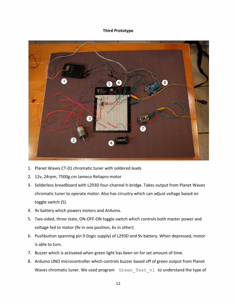
Third Prototype
1. Planet Waves CT-01 chromatic tuner with soldered leads
2. 12v, 24rpm, 7500g.cm Jameco Reliapro motor
3. Solderless breadboard with L293D four-channel h-bridge. Takes output from Planet Waves
chromatic tuner to operate motor. Also has circuitry which can adjust voltage based on
toggle switch (5).
4. 9v battery which powers motors and Arduino.
5. Two-sided, three state, ON-OFF-ON toggle switch which controls both master power and
voltage fed to motor (9v in one position, 6v in other).
6. Pushbutton spanning pin 9 (logic supply) of L293D and 9v battery. When depressed, motor
is able to turn.
7. Buzzer which is activated when green light has been on for set amount of time.
8. Arduino UNO microcontroller which controls buzzer based off of green output from Planet
Waves chromatic tuner. We used program Green_Test_v1 to understand the type of

13
output the tuner was sending and implemented Buzzer_Operator_v2 which
constantly monitors the green LED until it has counted a certain number of instances of the
LED in an activated state.
Pros:
High torque motor able to turn all string instrument tuners
Confirmation of tuning completion
Relatively simple circuitry
LED lights to indicate sharp/flat/correct
Requires only one power source (9v battery)
Pushbutton to activate motor
Variable speed
Master power switch
Cons:
Breadboard is not ideal for final implementation
Can only tune one string at a time
If string is more than one half-step off correct pitch, device will tune to wrong note
/*
Program Green_Test_v1
Creators:
Matthew Arbesfeld
Benjamin Edelstein
December 17, 2010
Program displays green light input value to serial
*/
void setup()
Serial.begin(9600);
void loop()
int greenVal = analogRead(A0);
Serial.print("Green: ");
Serial.println(greenVal);

14
/*
Program Buzzer_Operator_v2
Creators:
Matthew Arbesfeld
Benjamin Edelstein
December 17, 2010
Program increases counter if green is enabled and waits for counter to
reach threshold before producing buzzer signal
*/
const int BUZZER = 10;
const int BUZZER_TIME = 1000;
const int THREHOLD = 100;
int counter = 0;
void setup()
Serial.begin(9600);
pinMode(BUZZER, OUTPUT);
void loop()
int greenVal = analogRead(A0);
Serial.print("CURRENTLY GREEN... V: ");
Serial.print(greenVal);
Serial.print(" counter: ");
Serial.println(counter);
if(greenVal < 250)// < 250 is the value at which green LED is ON
counter++;
if(counter > THRESHOLD)
digitalWrite(BUZZER, HIGH);
delay(BUZZER_TIME);
digitalWrite(BUZZER, LOW);
delay(3000);
counter = 0;

15
Fourth Prototype
1. Illuminated rocker switch for master power
2. Ethernet jack to connect with hand-held device (8).
3. L293D controls polarity of motor current.
4. 9v (6x AA) battery holder
5. Korg CA-40 chromatic tuner
6. Relay which is controlled by Arduino to activate Korg tuner.
7. 3v voltage regulator to power Korg tuner.
8. Hand-held motor unit with activation button.
9. 5v buzzer which emits audible beep when tuning is complete
10. Toggle switch which controls buzzer ON/OFF status
11. Arduino UNO
Pros:
High torque motor able to turn all string instrument tuners
Confirmation of tuning completion
16
LED lights to indicate sharp/flat/correct
Requires only one power source (9v battery)
Pushbutton to activate motor
Master power switch
Hand-held control unit with modular connection
Buzzer ON/OFF switch
Relay to activate Korg tuner
Cons:
Breadboard is not ideal for final implementation
Can only tune one string at a time
If string is more than one half-step off correct pitch, device will tune to wrong note
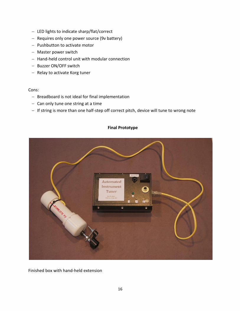
Final Prototype
Finished box with hand-held extension
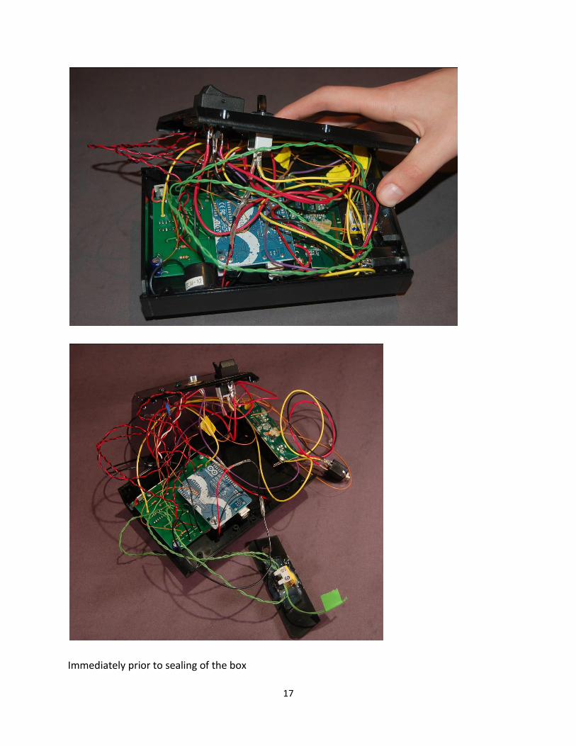
17
Immediately prior to sealing of the box

18
The PCB was designed in accordance with the fourth prototype using Eagle PCB software and
Viewplot was used to produce the images. The design was sent to Advanced Circuits for
fabrication.
Schematic view of PCB

19
Board view of PCB. Pink text is top silkscreen.

20
6 Data
See data table for values from all 6 trials.
0.0
0.5
1.0
1.5
2.0
2.5
3.0
Child (age 10)
Teenager (Matthew)
Teenager (Ben)
Amateur Musician (Age 45)
Novice (Age 60)
De
viat
ion
fro
m f
un
dam
en
tal f
req
ue
ncy
(H
z)
Participants
Comparison of tuning accuracy of six-string guitar
Tuning accuracy with conventional Korg
Tuning accuracy with our device
0.0
50.0
100.0
150.0
200.0
250.0
Tim
e (
seco
nd
s)
Participants
Comparison of tuning times of six-string guitar
Tuning time with conventional Korg tuner
Tuning time with our device
21
7 Data Analysis For time trial, data was collected by measuring total length of time to tune all six strings
from start to completion.
For accuracy analysis, an Intelli IMT-301 was used to measure the deviation of the note
from a reference pitch derived from an A at 440hz. Instead of measuring this value for
all six strings, two strings were chosen at random for each trial.
It should be noted that this is by no means a 100% accurate metric of the device’s real-
world performance. The small sample size and other environmental factors certainly
may have influenced the result of this study. However, one can ascertain certain trends
through this data.
All participants were in the immediate family of the conductors.
Points of interest:
The child had the largest time difference between the conventional tuning and tuning
with the device (83.4 seconds).
The most experienced string player (Ben) was slightly faster when using the
conventional tuning method over tuning with the device (14.9 seconds).
All two amateur musicians experienced similar time differences between conventional
tuning and tuning with the device (39.6 and 35.4 seconds, respectively).
Accuracy of all players was nearly proportional to their tuning time (ie. fastest tuner =
most accurate tuner).
All players had nearly the same accuracy with the device.
8 Cost Analysis
We estimate the following would be the costs of producing the device on a large scale:
Circuit board and microcontroller: $15 (includes logic and motor controller as well as
other basic circuit components)
Motor: $20
Housing and chassis materials: $5
Input and output devices (switches, LED’s, buzzers, LCD screen): $5
Total estimated cost: $45
22
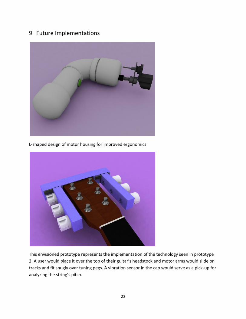
9 Future Implementations
L-shaped design of motor housing for improved ergonomics
This envisioned prototype represents the implementation of the technology seen in prototype
2. A user would place it over the top of their guitar’s headstock and motor arms would slide on
tracks and fit snugly over tuning pegs. A vibration sensor in the cap would serve as a pick-up for
analyzing the string’s pitch.
23
10 Conclusion
We successfully constructed a working prototype of our device which allows a user to tune any
type of string instrument with ease and accuracy. The entire device, if produced on a large
scale, is estimated to cost around 45 dollars, which puts it well within the reach of an average
consumer.
In our limited trials, we observed that amateur and experienced players alike both benefitted
from the device’s capabilities. Specifically, amateurs saw a consistent reduction in the time
needed to tune a six-string guitar. Furthermore, the device improved the tuning accuracy of all
participants.
The technology in this device can be extended to all instruments, not just those with strings. For
example, future versions could potentially tune woodwind, brass and percussion instruments.
Furthermore, section 9 (see previous page) describes potential extensions of our technology to
help streamline the tuning process.
In implementing our final prototype, we successfully fulfilled all of our engineering goals.
11 Acknowledgements
We would like to thank our chemistry teacher, Dr. Kumar, and our advisor, Ed Moriarty for their
council. Also, we would like to thank our parents for funding our project and for providing tools
and a space in which to build it.

24
12 Works Cited
Benward; Saker. Music: In Theory and Practice, Vol. I, p.47. Seventh Edition. 2003.
Dorf, R., and Svoboda, J.. Introduction to Electric Circuits, 3d ed. 1996.
Floyd, T., Principles of Electric Circuits, 5th ed. 1996.
Helmholtz, Hermann. On the Sensations of Tone. Trans: Alexander Ellis. Dover Publications. New
York, 1954.
Jorgensen, Owen. Tuning. Michigan State University Press, 1991.
Mottershead, Allen. "Circuit, Electric." Grolier Multimedia Encyclopedia. Grolier Online, 2011.
Web. 12 Feb. 2011.
Parncutt, R. (1989). Harmony: A psychoacoustical approach. Berlin: Springer-Verlag, 1989.
Parrett, R., DC-AC Circuits (1991).
"Pitch." Encyclopedia Americana. Grolier Online, 2011. Web. 11 Feb. 2011.
Schmidt, Maik. Arduino: A Quick Start Guide (1st ed.) Pragmatic Bookshelf, 1995.
Vergara, William C. "Sound and Ultrasonics." Reviewed by Larry Kettlekamp. The New Book of
Knowledge. Grolier Online, 2011. Web. 11 Feb. 2011.
Warren, John-David; Adams, Josh; Molle, Harald. Arduino Robotics (1st ed.). Apress, 2011.