automated monitoring systems mss mdspe fall conference
TRANSCRIPT
Automated Monitoring Systems
MSS MDSPE Fall Conference
Craig Williams, PS
Leica Monitoring Solution
Content
1. Overview
2. Different technologies used
3. Software
4. Example projects
5. Scanning for deformation
6. Vertical alignment
7. Project photos
Leica Monitoring Solution
Overview
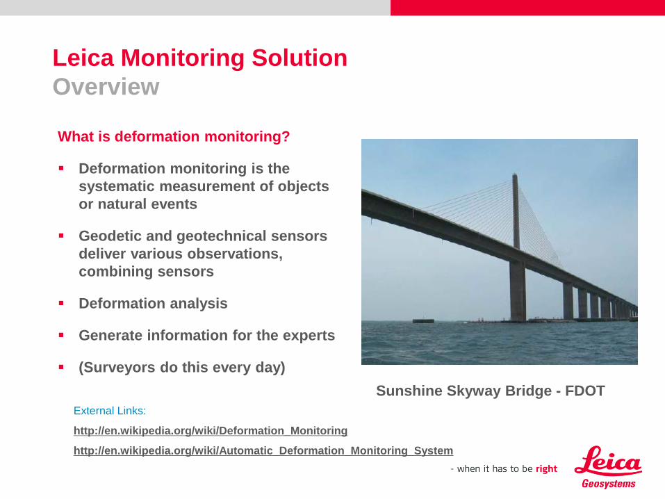
What is deformation monitoring?
Deformation monitoring is the
systematic measurement of objects
or natural events
Geodetic and geotechnical sensors
deliver various observations,
combining sensors
Deformation analysis
Generate information for the experts
(Surveyors do this every day)
External Links:
http://en.wikipedia.org/wiki/Deformation_Monitoring
http://en.wikipedia.org/wiki/Automatic_Deformation_Monitoring_System
Sunshine Skyway Bridge - FDOT

Leica Monitoring Solution
Overview
When is monitoring required?
Potential problem
Construction creates instability
Long-term deformation
Safety of public and workers
Erosion (extended life time)
Climate changes
Aging infrastructure

Leica Monitoring Solution
Overview
Why automate the system?
Safety
Reduce risk
Real time information
Ability to respond rather than
react
Save our clients money on short
term or long term projects
A new “niche”

Leica Monitoring Solution
Overview
Reduce risk! We want to avoid this.
Monitoring projects and technologies
Examples and what do we ask?
What are we monitoring?
What is the amount of movement we are looking for? 1.0’ or .001’
What type of movement are we looking for? 1d, 2d, 3d?
Frequency or measurements?
Amount of points to be monitored?
Real Time or post processed?
Are alerts required and at what level?
Things to consider as we go forward.

The surveying and monitoring workhorse
Please insert a picture
(Insert, Picture, from file).
Size according to grey field
(10 cm x 25.4 cm).
Scale picture: highlight, pull corner point
Cut picture: highlight, choose the cutting icon from the picture tool bar, click on a
side point and cut
Automated Monitoring Systems
9
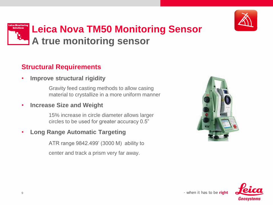
Leica Nova TM50 Monitoring Sensor
A true monitoring sensor
Structural Requirements
• Improve structural rigidity
Gravity feed casting methods to allow casing
material to crystallize in a more uniform manner
• Increase Size and Weight
15% increase in circle diameter allows larger
circles to be used for greater accuracy 0.5”
• Long Range Automatic Targeting
ATR range 9842.499’ (3000 M) ability to
center and track a prism very far away.
10
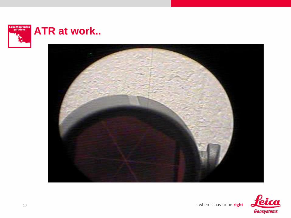
ATR at work..
11
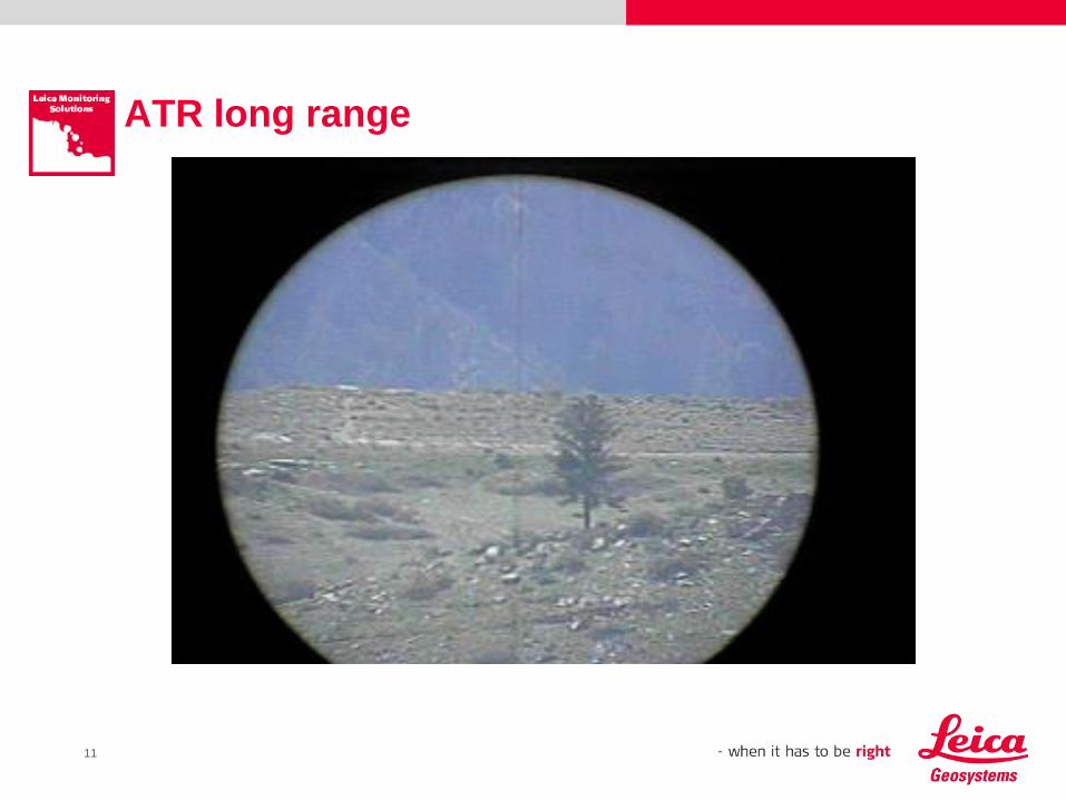
ATR long range
12
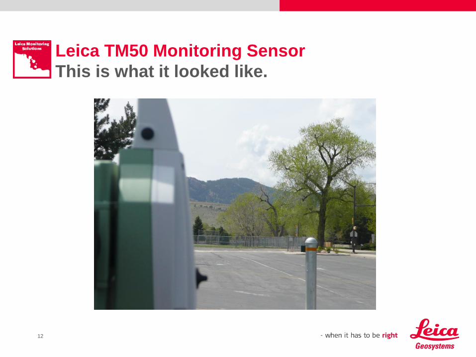
Leica TM50 Monitoring Sensor
This is what it looked like.
13
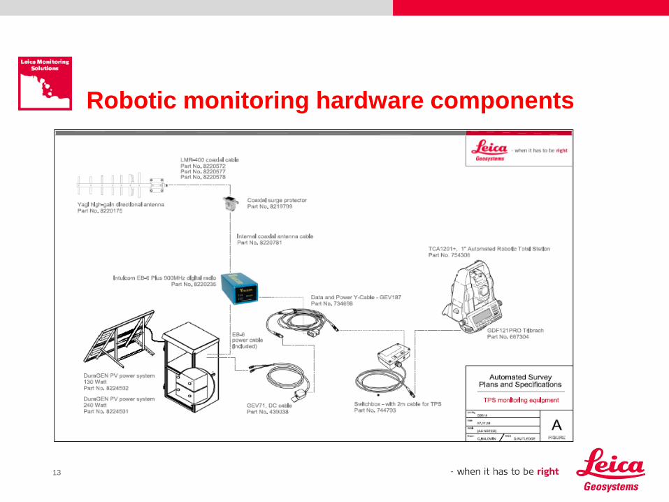
Robotic monitoring hardware components
14
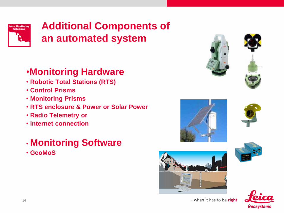
•Monitoring Hardware• Robotic Total Stations (RTS)
• Control Prisms
• Monitoring Prisms
• RTS enclosure & Power or Solar Power
• Radio Telemetry or
• Internet connection
• Monitoring Software• GeoMoS
Additional Components of
an automated system
15
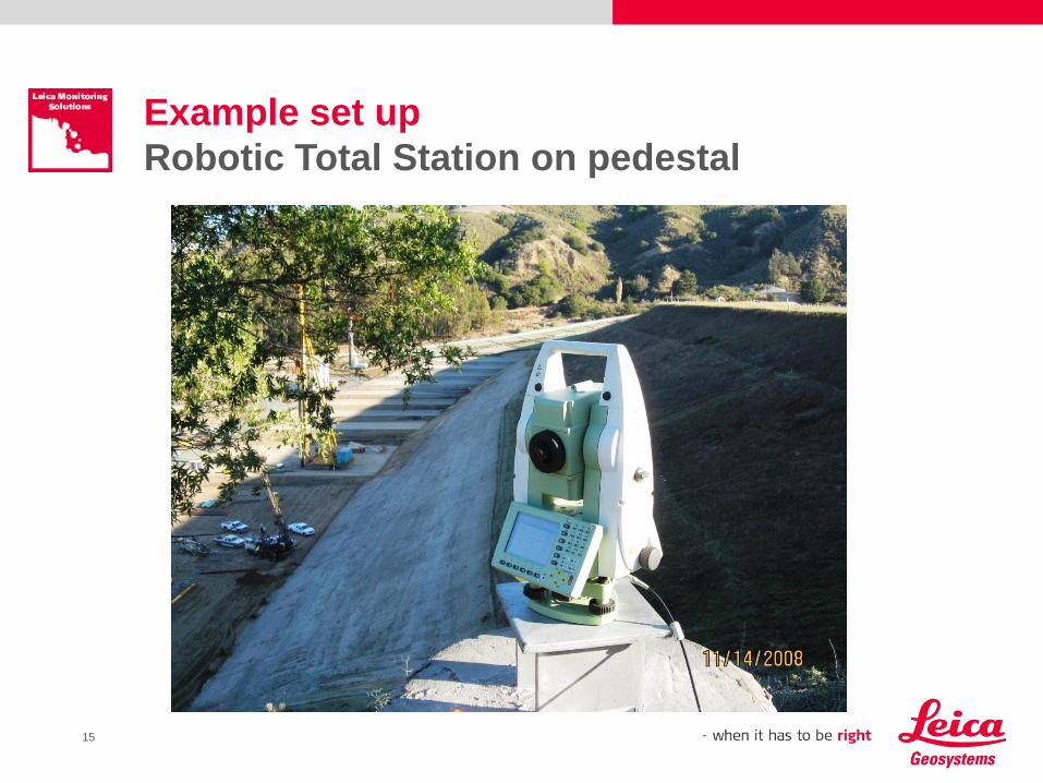
Example set up
Robotic Total Station on pedestal
1616
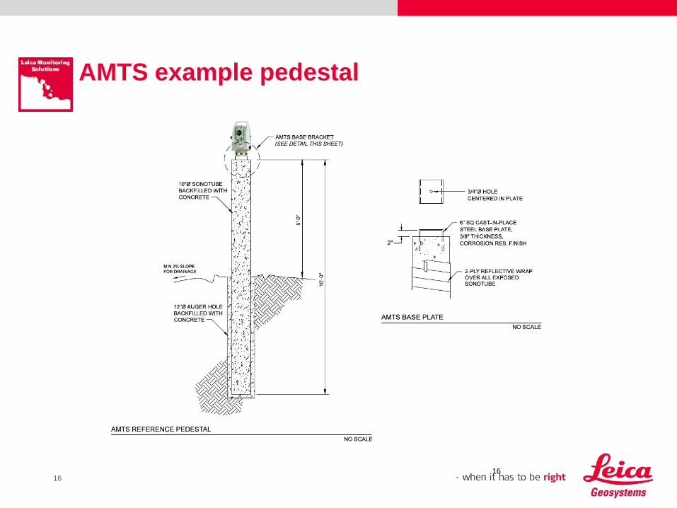
AMTS example pedestal
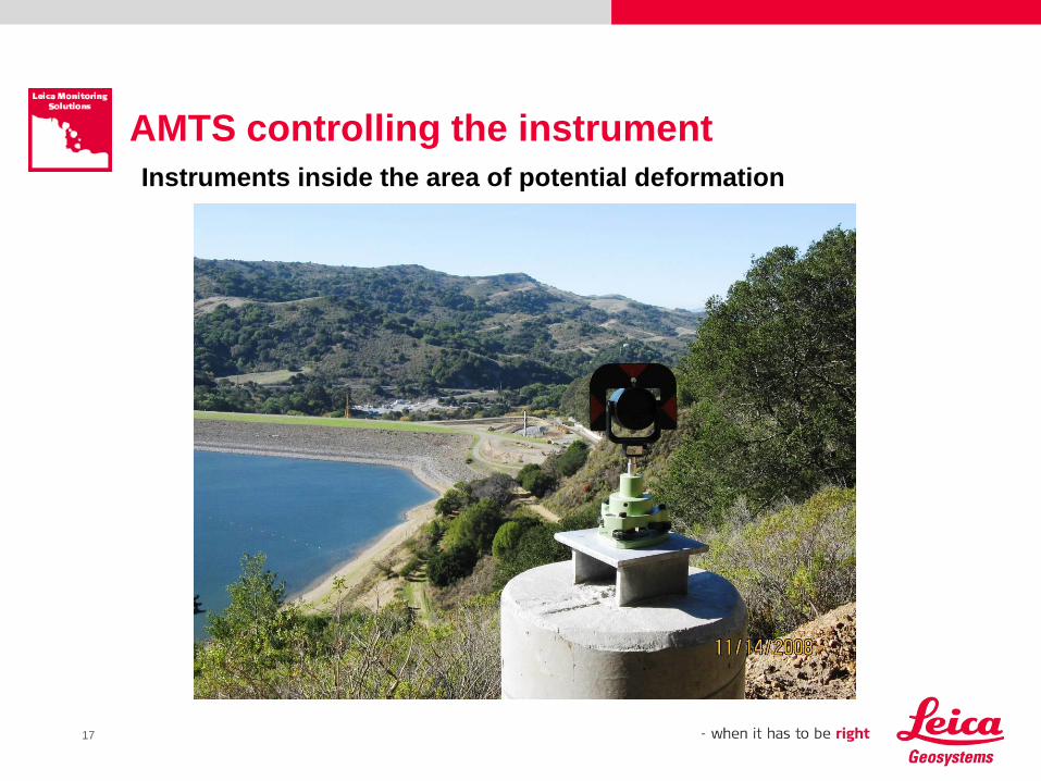
17
AMTS controlling the instrument
Instruments inside the area of potential deformation
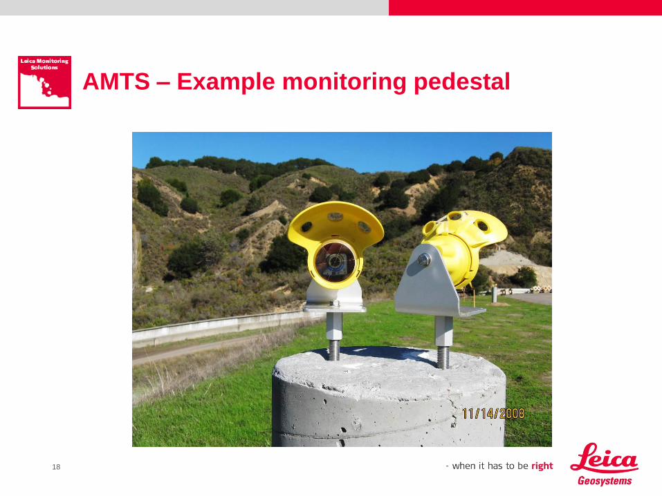
18
AMTS – Example monitoring pedestal
19
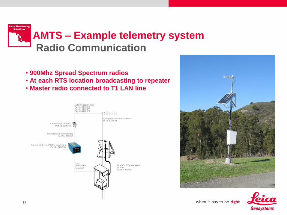
• 900Mhz Spread Spectrum radios
• At each RTS location broadcasting to repeater
• Master radio connected to T1 LAN line
AMTS – Example telemetry system
Radio Communication
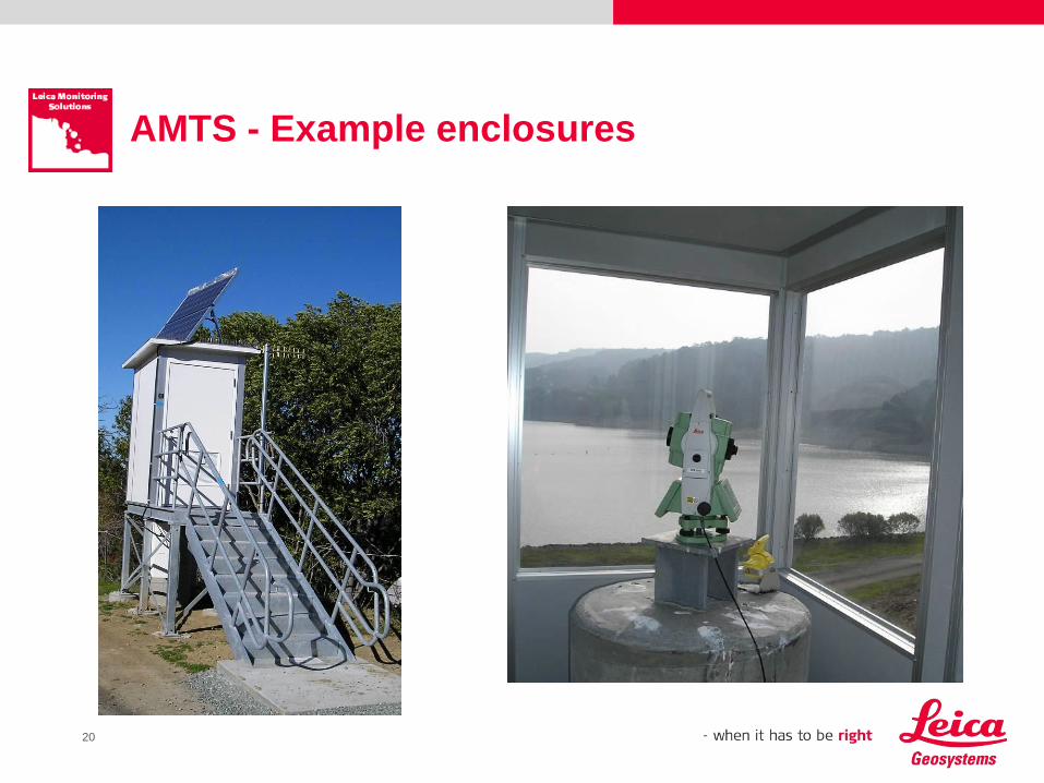
20
AMTS - Example enclosures
21
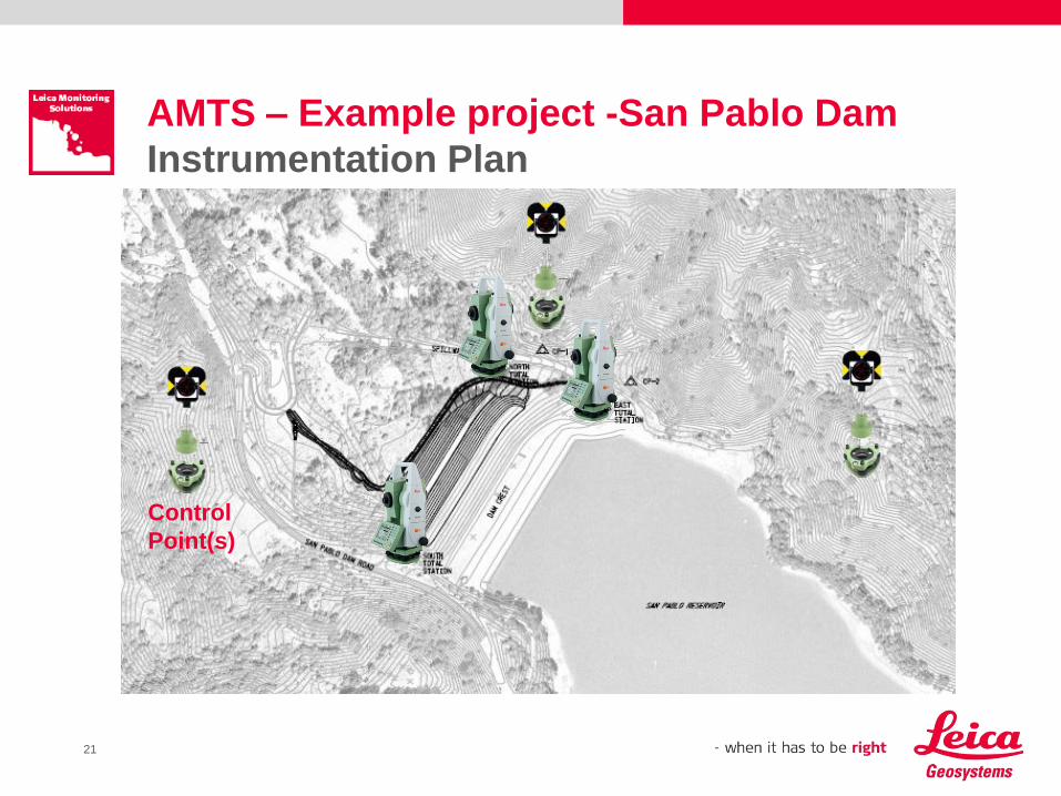
AMTS – Example project -San Pablo Dam
Instrumentation Plan
Control
Point(s)
22
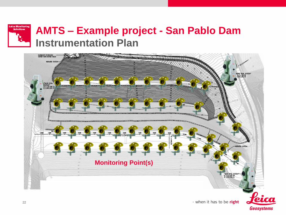
AMTS – Example project - San Pablo Dam
Instrumentation Plan
Monitoring Point(s)
23
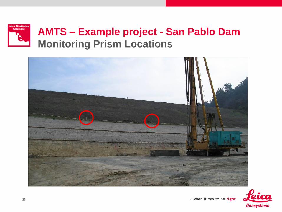
AMTS – Example project - San Pablo Dam
Monitoring Prism Locations
24
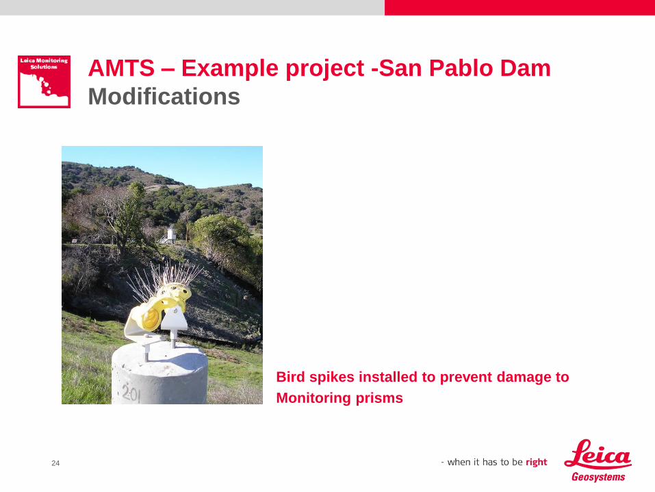
AMTS – Example project -San Pablo Dam
Modifications
Bird spikes installed to prevent damage to
Monitoring prisms
25
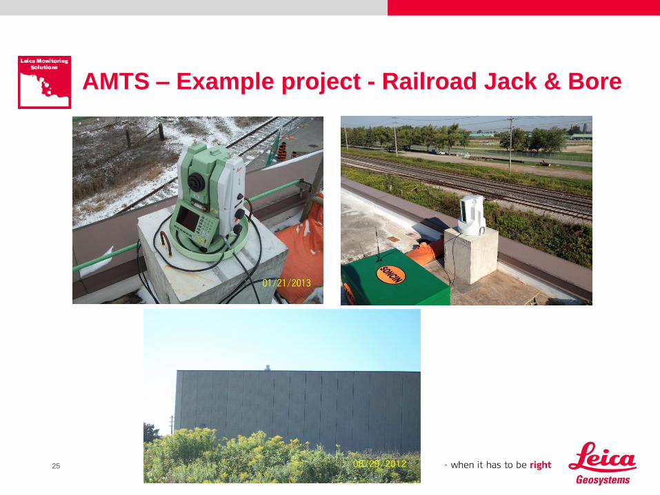
AMTS – Example project - Railroad Jack & Bore
27
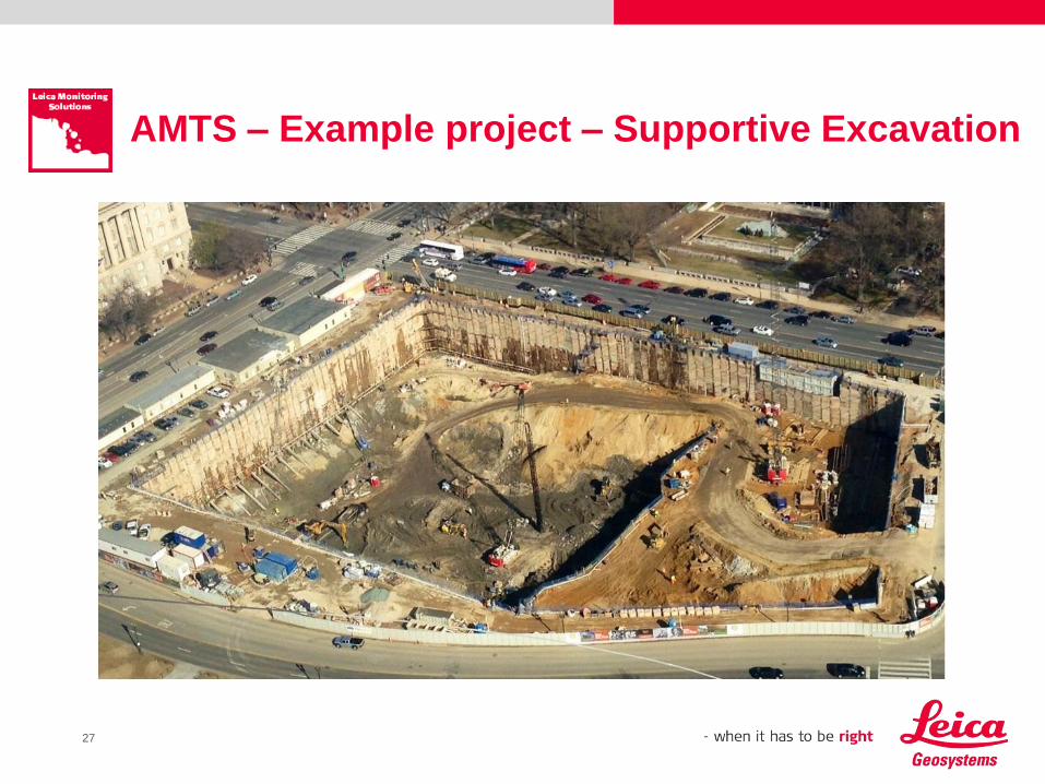
AMTS – Example project – Supportive Excavation
28
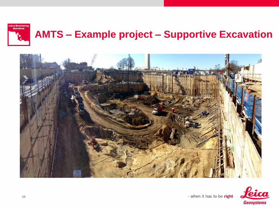
AMTS – Example project – Supportive Excavation
29
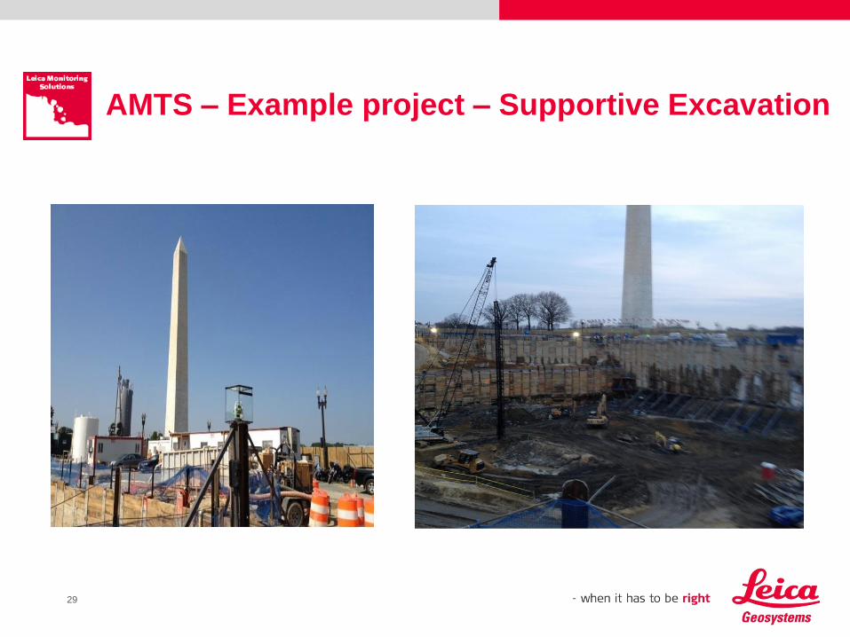
AMTS – Example project – Supportive Excavation
30
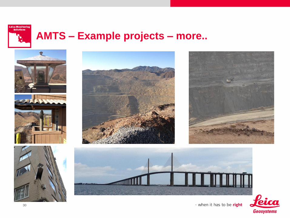
AMTS – Example projects – more..
31
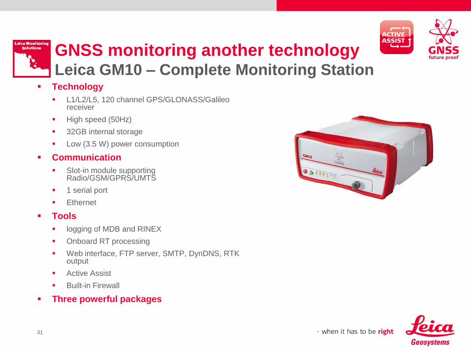
GNSS monitoring another technologyLeica GM10 – Complete Monitoring Station
Technology
L1/L2/L5, 120 channel GPS/GLONASS/Galileo receiver
High speed (50Hz)
32GB internal storage
Low (3.5 W) power consumption
Communication
Slot-in module supporting Radio/GSM/GPRS/UMTS
1 serial port
Ethernet
Tools
logging of MDB and RINEX
Onboard RT processing
Web interface, FTP server, SMTP, DynDNS, RTK output
Active Assist
Built-in Firewall
Three powerful packages
32
GNSS Monitoring Solutions Overview
Static Monitoring Solution
Post Processing monitoring on short baselines. It is modular solution using flexibility of GNSS
Monitoring Station and powerful PP algorithms of GNSS Spider to provide best possible results
in near real time. Deformation analysis is supported with GeoMoS HiSpeed and advanced
GeoMoS Adjustment tool.
Dynamic Monitoring Solution
Real time monitoring for reliable and fast movement detection. Sophisticated RT solution takes
advantage of powerful RT positioning module and high frequency measurements. GeoMoS
HiSpeed performs high rate deformation analysis.
GLOBAL Monitoring Solution
Highest Performance GNSS Monitoring for long baselines and controlling of reference stations.
Full service based on scientific GNSS processing package BERNESE integrated in IERS global
earth monitoring provides absolute position control of reference points with highest accuracy.
34
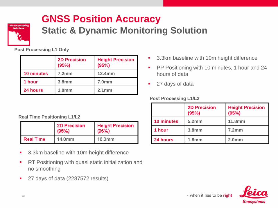
GNSS Position AccuracyStatic & Dynamic Monitoring Solution
2D Precision
(95%)
Height Precision
(95%)
10 minutes 7.2mm 12.4mm
1 hour 3.8mm 7.0mm
24 hours 1.8mm 2.1mm
2D Precision
(95%)
Height Precision
(95%)
10 minutes 5.2mm 11.8mm
1 hour 3.8mm 7.2mm
24 hours 1.8mm 2.0mm
Post Processing L1/L2
Post Processing L1 Only
3.3km baseline with 10m height difference
PP Positioning with 10 minutes, 1 hour and 24
hours of data
27 days of data
Real Time Positioning L1/L2
3.3km baseline with 10m height difference
RT Positioning with quasi static initialization and
no smoothing
27 days of data (2287572 results)
35
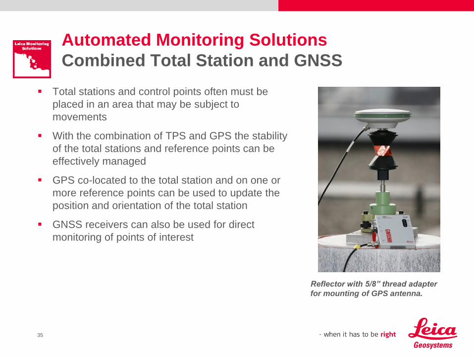
Automated Monitoring Solutions
Combined Total Station and GNSS
Total stations and control points often must be
placed in an area that may be subject to
movements
With the combination of TPS and GPS the stability
of the total stations and reference points can be
effectively managed
GPS co-located to the total station and on one or
more reference points can be used to update the
position and orientation of the total station
GNSS receivers can also be used for direct
monitoring of points of interest
Reflector with 5/8” thread adapter
for mounting of GPS antenna.
36
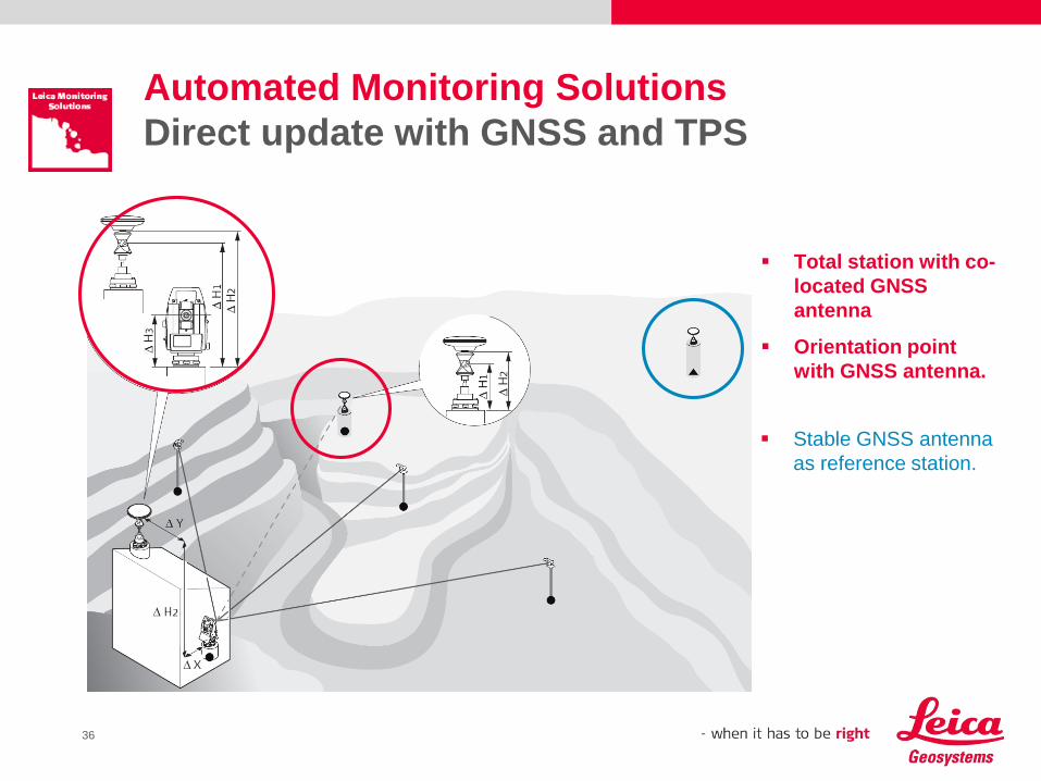
Automated Monitoring Solutions
Direct update with GNSS and TPS
Total station with co-
located GNSS
antenna
Orientation point
with GNSS antenna.
Stable GNSS antenna
as reference station.
37
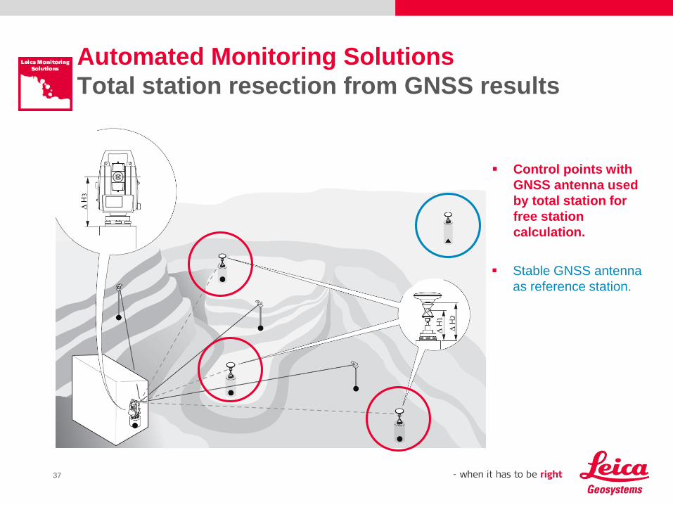
Automated Monitoring Solutions
Total station resection from GNSS results
Control points with
GNSS antenna used
by total station for
free station
calculation.
Stable GNSS antenna
as reference station.
38
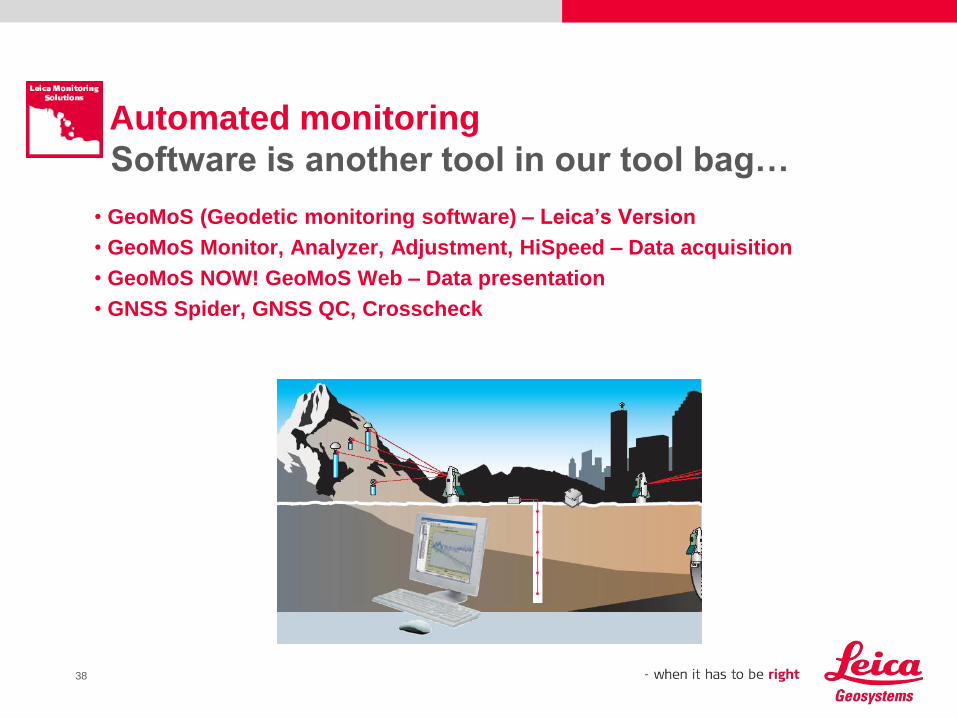
• GeoMoS (Geodetic monitoring software) – Leica’s Version
• GeoMoS Monitor, Analyzer, Adjustment, HiSpeed – Data acquisition
• GeoMoS NOW! GeoMoS Web – Data presentation
• GNSS Spider, GNSS QC, Crosscheck
Automated monitoring
Software is another tool in our tool bag…
39
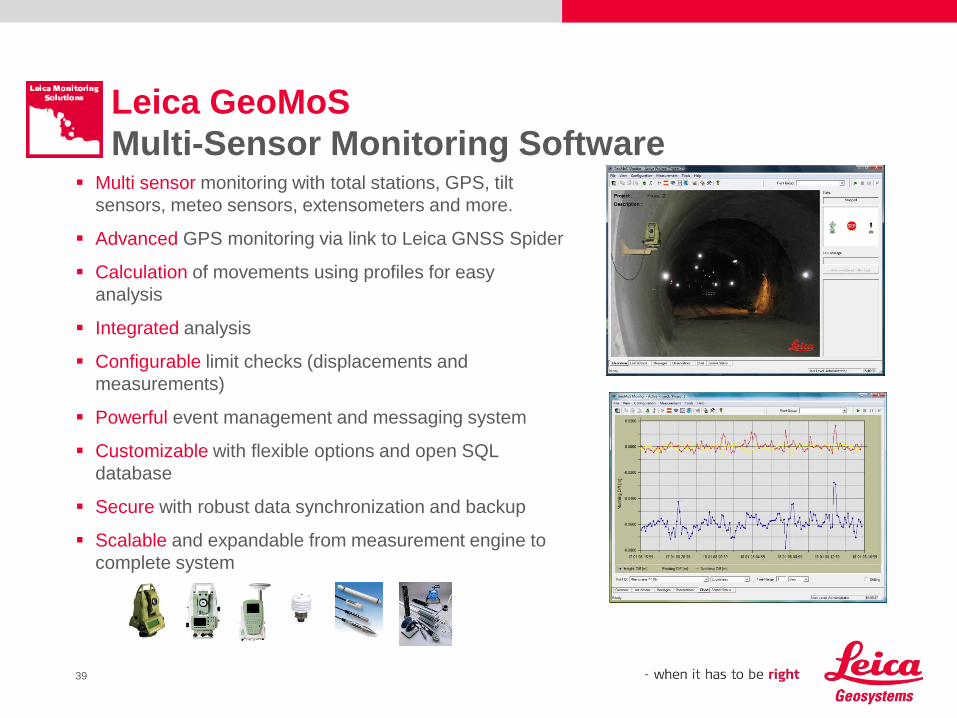
Leica GeoMoS
Multi-Sensor Monitoring Software Multi sensor monitoring with total stations, GPS, tilt
sensors, meteo sensors, extensometers and more.
Advanced GPS monitoring via link to Leica GNSS Spider
Calculation of movements using profiles for easy
analysis
Integrated analysis
Configurable limit checks (displacements and
measurements)
Powerful event management and messaging system
Customizable with flexible options and open SQL
database
Secure with robust data synchronization and backup
Scalable and expandable from measurement engine to
complete system
40
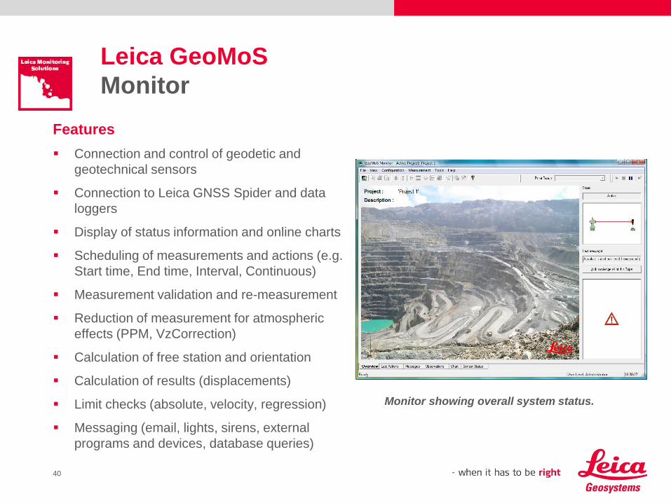
Leica GeoMoS
Monitor
Features
Connection and control of geodetic and
geotechnical sensors
Connection to Leica GNSS Spider and data
loggers
Display of status information and online charts
Scheduling of measurements and actions (e.g.
Start time, End time, Interval, Continuous)
Measurement validation and re-measurement
Reduction of measurement for atmospheric
effects (PPM, VzCorrection)
Calculation of free station and orientation
Calculation of results (displacements)
Limit checks (absolute, velocity, regression)
Messaging (email, lights, sirens, external
programs and devices, database queries)
Monitor showing overall system status.
41
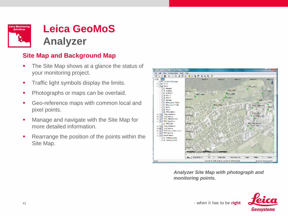
Leica GeoMoS
Analyzer
Site Map and Background Map
The Site Map shows at a glance the status of
your monitoring project.
Traffic light symbols display the limits.
Photographs or maps can be overlaid.
Geo-reference maps with common local and
pixel points.
Manage and navigate with the Site Map for
more detailed information.
Rearrange the position of the points within the
Site Map.
Analyzer Site Map with photograph and
monitoring points.
42
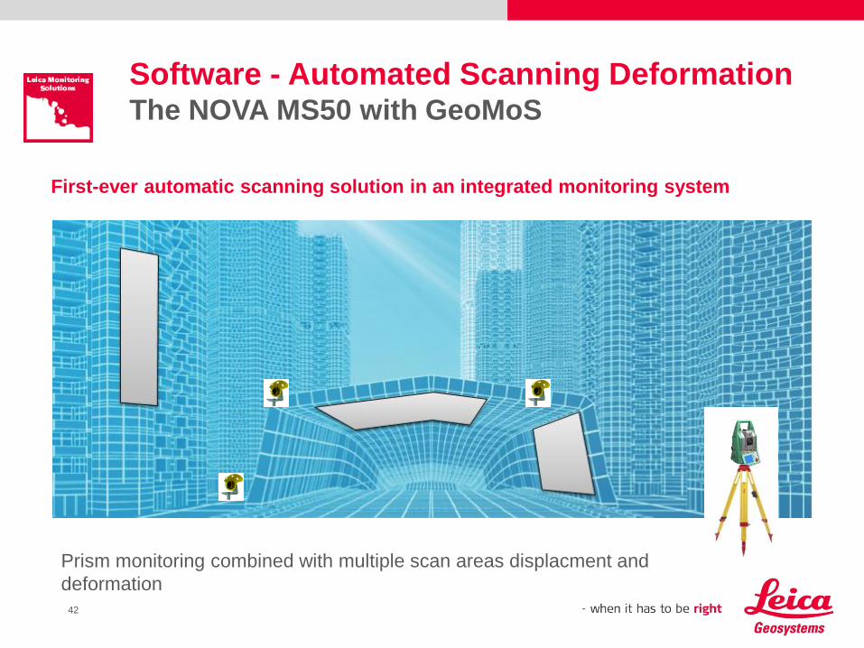
First-ever automatic scanning solution in an integrated monitoring system
Software - Automated Scanning DeformationThe NOVA MS50 with GeoMoS
Prism monitoring combined with multiple scan areas displacment and
deformation
43
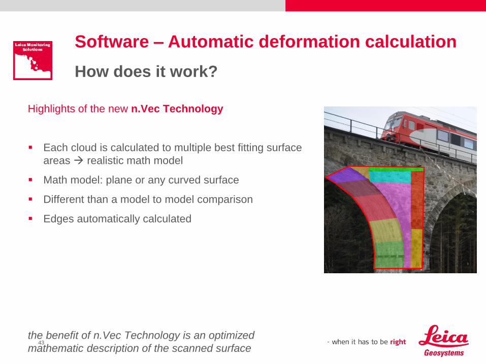
Software – Automatic deformation calculation
How does it work?
Highlights of the new n.Vec Technology
Each cloud is calculated to multiple best fitting surface
areas realistic math model
Math model: plane or any curved surface
Different than a model to model comparison
Edges automatically calculated
the benefit of n.Vec Technology is an optimized
mathematic description of the scanned surface
44
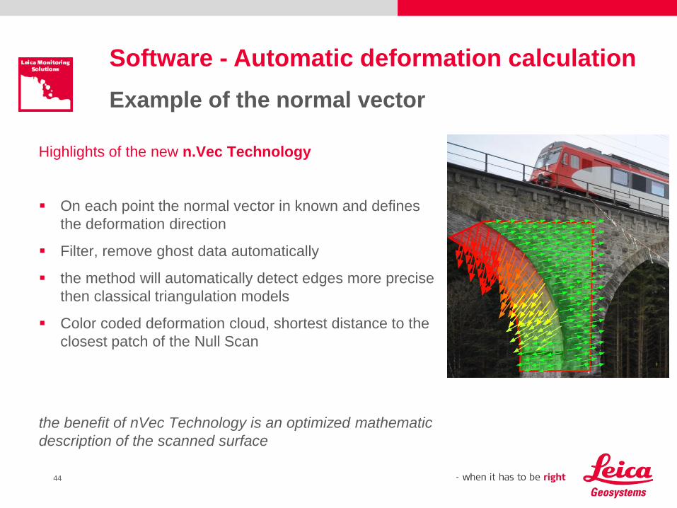
Software - Automatic deformation calculation
Example of the normal vector
Highlights of the new n.Vec Technology
On each point the normal vector in known and defines
the deformation direction
Filter, remove ghost data automatically
the method will automatically detect edges more precise
then classical triangulation models
Color coded deformation cloud, shortest distance to the
closest patch of the Null Scan
the benefit of nVec Technology is an optimized mathematic
description of the scanned surface
45
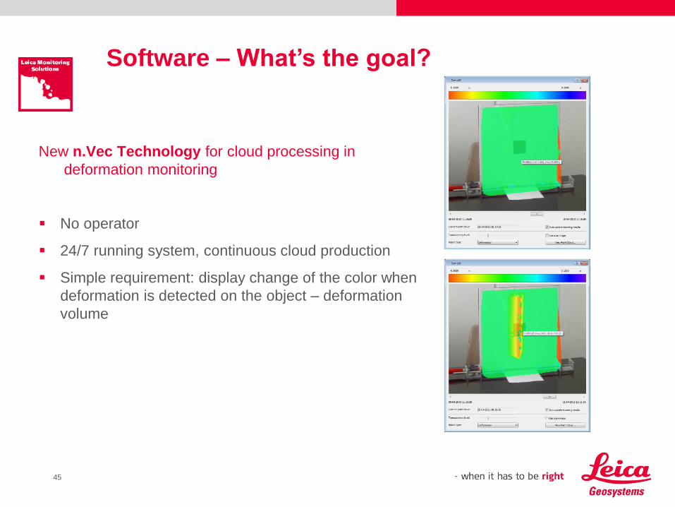
Software – What’s the goal?
New n.Vec Technology for cloud processing in
deformation monitoring
No operator
24/7 running system, continuous cloud production
Simple requirement: display change of the color when
deformation is detected on the object – deformation
volume
46
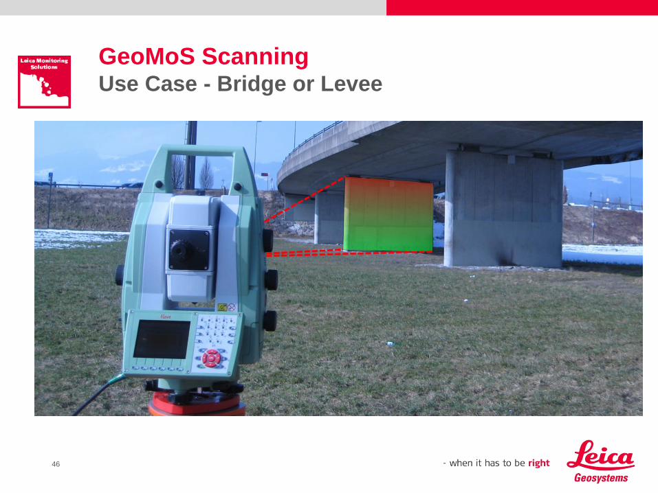
GeoMoS ScanningUse Case - Bridge or Levee
47
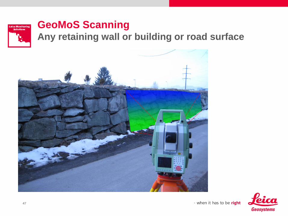
GeoMoS ScanningAny retaining wall or building or road surface
48
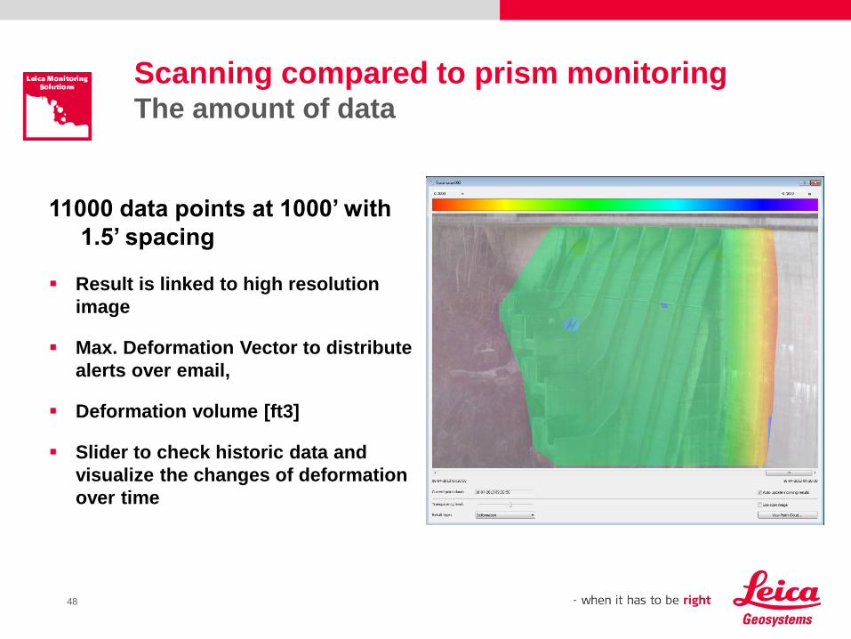
Scanning compared to prism monitoringThe amount of data
11000 data points at 1000’ with
1.5’ spacing
Result is linked to high resolution
image
Max. Deformation Vector to distribute
alerts over email,
Deformation volume [ft3]
Slider to check historic data and
visualize the changes of deformation
over time
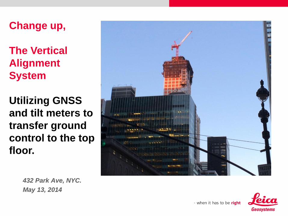
432 Park Ave, NYC.
May 13, 2014
Change up,
The Vertical
Alignment
System
Utilizing GNSS
and tilt meters to
transfer ground
control to the top
floor.

Please insert a picture
(Insert, Picture, from file).
Size according to grey field
(10 cm x 25.4 cm).
Scale picture: highlight, pull corner point
Cut picture: highlight, choose the cutting icon from the picture tool bar, click on a
side point and cut
The first USA installation:
World Trade Center One – Building Tall & Straight

51
The Vertical Alignment System
Building tall and straight, World Trade Center One.
Increasing interest in the construction of super high-rise buildings
The footprint of these structures are becoming smaller thus introducing
significant movements of the building at upper levels during construction
It is essential that a straight “element” be constructed so that, theoretically,
the building moves around its design center point due to varying loads.
This ideal situation is rarely achieved due to differential raft settlement,
differential concrete shortening, construction tolerances, sun radiation, wind
and crane loads.
If all conditions were neutral then the “element” would stand exactly vertical.
The movement of the structure creates several problems for the correct layout
of concrete formwork or steel erection work; at any particular instant in time
you need to know exactly how much the building is offset from its design
position and at the same time you need to know your precise position at the
instrument location.
The Vertical Alignment System
Motivation
52
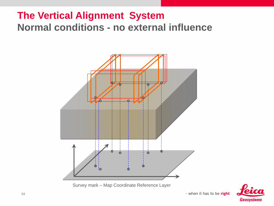
The Vertical Alignment System
Normal conditions - no external influence
Survey mark – Map Coordinate Reference Layer
53
Leica Geosystems developed a procedure using GNSS observations combined
with a precision inclination sensor to obtain reliable coordinated points at the top of
a building or any other structure.
The GNSS coordinated points will be corrected for tilt and then will be sighted by a
Total Station to compute a resection to establish its coordinate and orientation.
To obtain the GNSS positions, We are streaming the GNSS observations through
a communication infrastructure to software that will process and report the final
results.
To obtain the tilt readings, We are streaming the tilt observations through a
seperate communication infrastructure to software that records the observations
and computes the tilt corrections that may be applied.
Core Wall Survey System
Solution
54
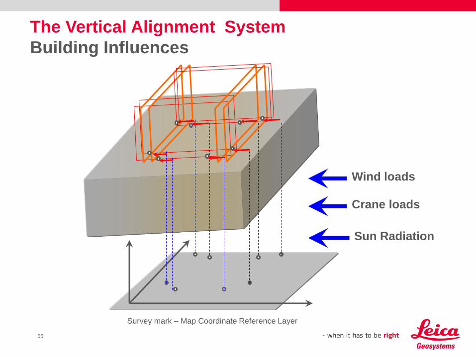
The Vertical Alignment System
Building Influences
Wind loads
Crane loads
Sun Radiation
Survey mark – Map Coordinate Reference Layer
55
56
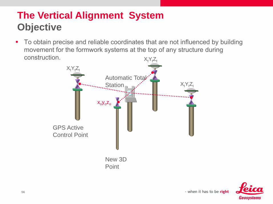
To obtain precise and reliable coordinates that are not influenced by building
movement for the formwork systems at the top of any structure during
construction.
The Vertical Alignment System
Objective
XtYtZt
xoyozo
GPS Active
Control Point
Automatic Total
Station
New 3D
Point
XtYtZt
XtYtZt
57
Setup a Theodolite or Total Station on known grid lines or ground control points at
the street level
Raise the alignments with telescope to the upper floor on 4 sides or raise the
control points from the last floor
Average the final intersection axis at the next floor
When the street level points are “lost” or too far we need to use a plumb bob…
On very high floors, this has to be done at night or early morning when the building
is “hopefully” in its neutral stage
Then form or steel work layout can start with these grid lines
This traditional work process such as it was is time consuming and does not
keep pace with today’s rapid per floor construction cycle.
The Vertical Alignment System
Traditional Work Process & Short Const. Cycle
58
The survey control process is utilizing a combination of GNSS positioning and
inclination sensors
Three local GNSS antennas with a total station will be used to determine the
precise coordinates of control points that are established on the top floor.
The inclination sensors will measure the amount of tilt in x and y that the building is
offset from its design position at any one moment and this is then applied as a
correction to the coordinates of the control points. The resulting corrected positions
will ensure that the building is constructed as straight element regardless of the
movement of the building due to wind load, crane loads, … etc.
Tilt is only needed above a certain height...
The Vertical Alignment System
Concept
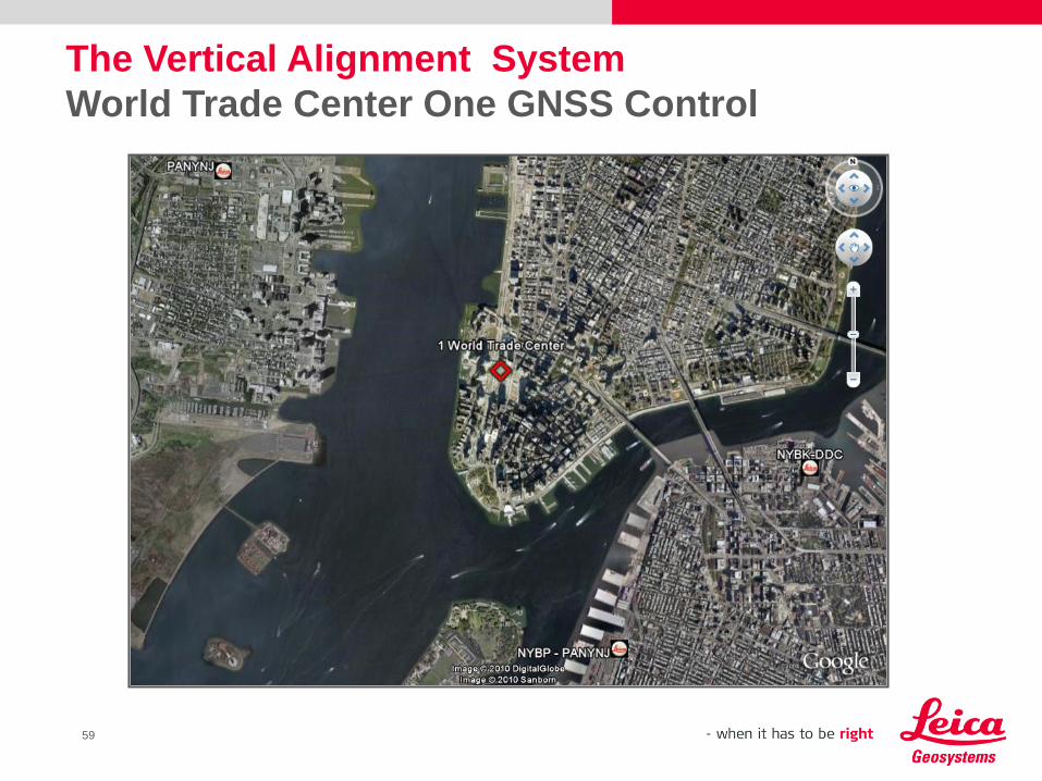
The Vertical Alignment System
World Trade Center One GNSS Control
59
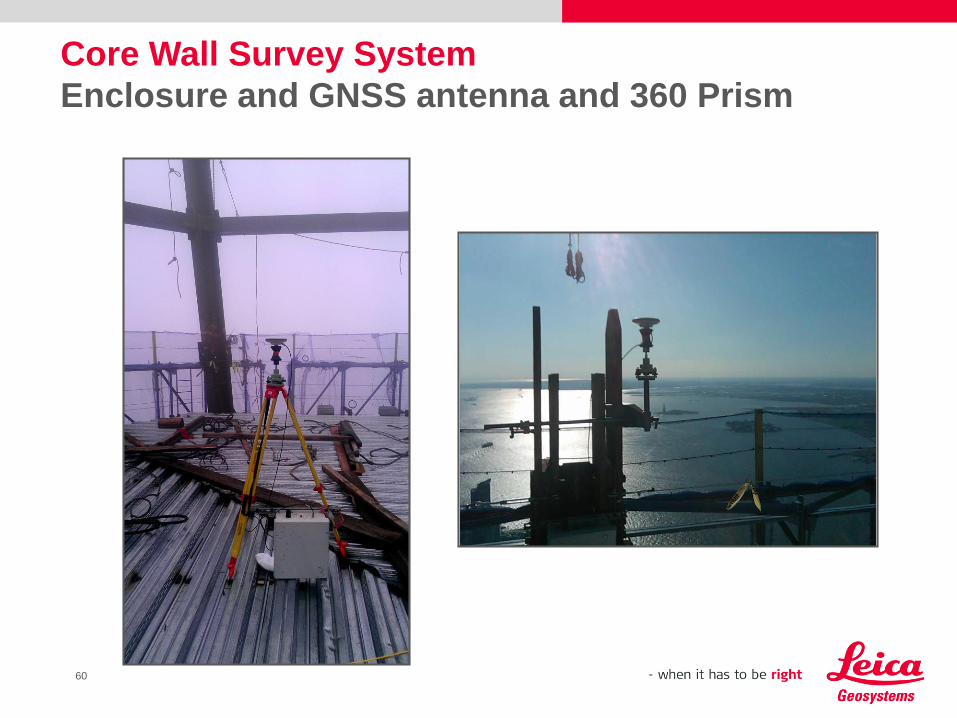
Core Wall Survey System
Enclosure and GNSS antenna and 360 Prism
60

The Vertical Alignment System
Typical Deployment
61
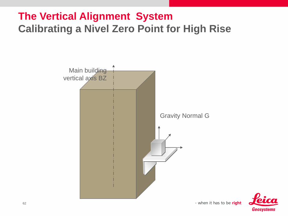
The Vertical Alignment System
Calibrating a Nivel Zero Point for High Rise
Main building
vertical axis BZ
Gravity Normal G
62
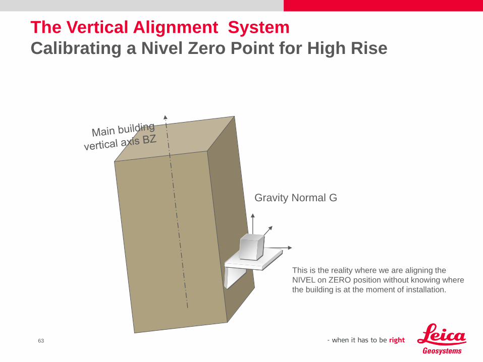
Gravity Normal G
This is the reality where we are aligning the
NIVEL on ZERO position without knowing where
the building is at the moment of installation.
The Vertical Alignment System
Calibrating a Nivel Zero Point for High Rise
63
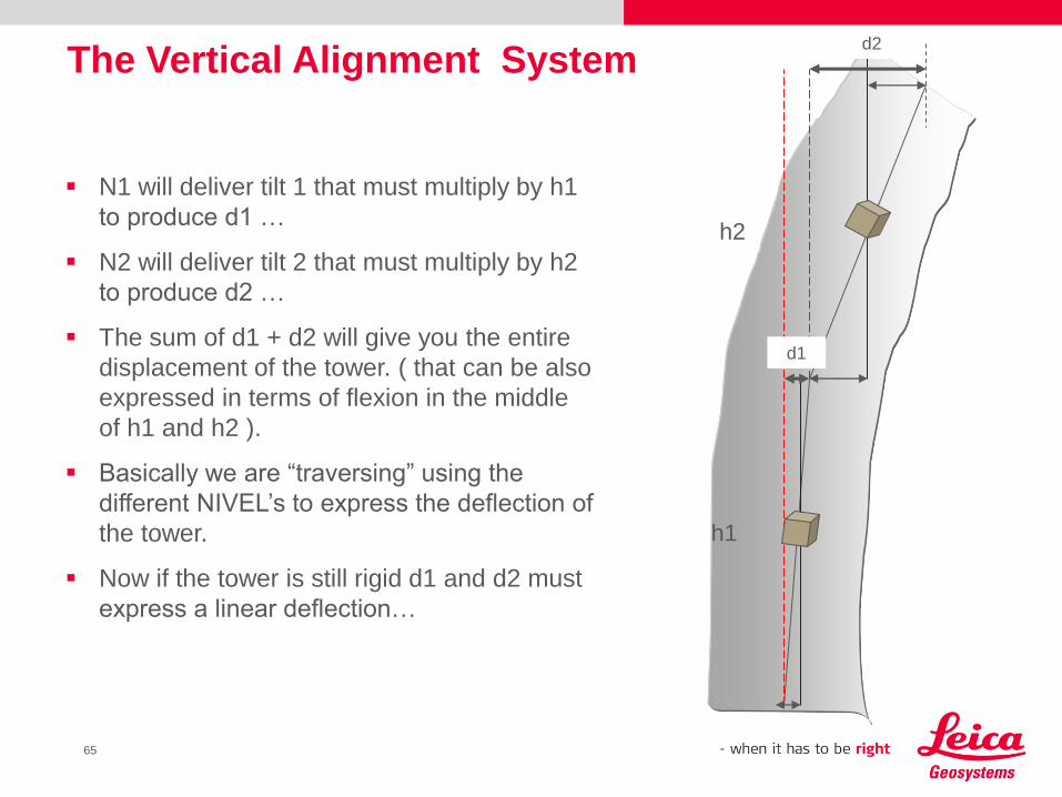
N1 will deliver tilt 1 that must multiply by h1
to produce d1 …
N2 will deliver tilt 2 that must multiply by h2
to produce d2 …
The sum of d1 + d2 will give you the entire
displacement of the tower. ( that can be also
expressed in terms of flexion in the middle
of h1 and h2 ).
Basically we are “traversing” using the
different NIVEL’s to express the deflection of
the tower.
Now if the tower is still rigid d1 and d2 must
express a linear deflection…
The Vertical Alignment System
h1
h2
d1
d2
65
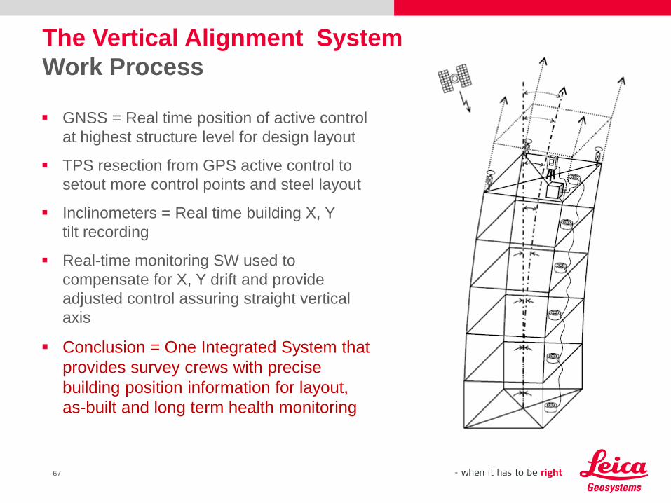
GNSS = Real time position of active control
at highest structure level for design layout
TPS resection from GPS active control to
setout more control points and steel layout
Inclinometers = Real time building X, Y
tilt recording
Real-time monitoring SW used to
compensate for X, Y drift and provide
adjusted control assuring straight vertical
axis
Conclusion = One Integrated System that
provides survey crews with precise
building position information for layout,
as-built and long term health monitoring
The Vertical Alignment System
Work Process
67
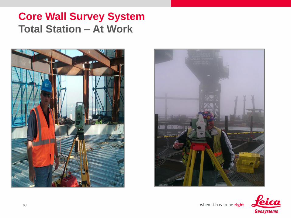
Core Wall Survey System
Total Station – At Work
68

Vertical alignment system
New York City, Oklahoma City, Long Beach, Boston

Photo’s..
71