automated laser depainting of aircraft survey of …if the enabling technologies were available to...
TRANSCRIPT
WL-TR-91-4024
AD-A250 380
AUTOMATED LASER DEPAINTING OF AIRCRAFTSURVEY OF ENABLING TECHNOLOGIES
0 Al
Peter W. KopfDean Pichon, et al.Arthur D. Little, Inc.25 Acorn ParkCambridge, MA 02140-2390
January 1991
Final Report for the Period May 1989 to January 1991
Approved for public release; distribution unlimited Ilk
MYO a.1992.
WRIGHT LABORATORY 4
MATERIALS DIRECTORATEAIR FORCE SYSTEMS COMMANDWRIGHT-PATTERSON AIR FORCE BASE, OHIO 45433-6533
92-12244• . •I /1 1111 /n1 //l ll/li!Ii$ ii/lt[ll

NOTICE
When Government drawings, specifications, or other data are used forany purpose other than in connection with a definitely Government-relatedprocurement, the United States Government incurs no responsibility or anyobligation whatsoever. The fact that the governnent may have formulated orin any way supplied the said drawings, specifications, or other data, is notto be regarded by implication, or otherwise in any manner construed, aslicensing the holder, or any other person or corporation; or as conveyingany rights or permission to manufacture, use, or sell any patented inventionthat may in any way be related thereto.
This report Is releasable to the National Technical tnformation Service(NTIS). At NTIS, it will be available to the general public, includingforeign nations.
This technical report has been reviewed and is approved for publica-tion.
GARY D. KUER, Captain USAF THEODORE J REIIKART, ChiefMaterials Behavior & Evaluation Group Materials Engineering BranchMaterials Engineering Branch Systems Support DivisionSystems Support Division
FOR THE COMMANDER
THOMAS D. COOPER, ChiSystems Support DivisionMaterials Directorate
If your address has changed, if you wish to be removed from our mailinglist, or if the addressee is no longer employed by your organization pleasenotify WL/MLSE , WPAFB, OH 45433-_6 to help us maintain a currentmailing list.
Copies of this report should not be returned unless return is required bysecurity considerations, contractual obligations, or notice on a specificdocument.

UNCLASSIFIEDSECURITY CLASSIFICATION O? THIS AE____________
REPORT DOCUMENTATION PAGE O)"%NO.14-a8la REPORT SECURITY CLASSIFICATION 1b, RESTRICTIVE MARKINGS
UTNCLASS IFIED None2a. SECURITY CLASSIFICATION AUTHORITY 3 DISITRIUTION /AVAILANILITY OF REPORT
NA Approved for public Release;2b. DE CLASSIFICATION / DOWNGRADING SCHEDULE d is tribut ion unlimited
NA _ _ _ _ _ _ _ _ _ _ _ _ _ _ _ _ _ _ _ _ _ _ _
4. PERFORMING ORGANIZATION REPORT NUMBER(S) S. MAONITORING ORGANIZATION REPORT NUMBER(S)Arthur D. Little No. 60882 WL-TR-91-4024
6oGa NAME OF PERFORMING ORGANIZATION 6~b. OFFICE SYMBOL 7&. NAME OF MONITORING ORGANIZATIONArthur D. Little Inc (fok@ Wright Laboratory -MKaterials .it8garate
6c. ADDRESS (CIty, Store, arid ZIP Code) 7b. ADDRESS(City, State, .nd ZIPE je~
25 Acorn Park WL/MLSECambridge MA 02140-2390 Wright Patterson AFB, OH 45433-6533
So. NAME OF FUNDING /SPONSORING 8 b. OFFICE SYMBOL 9. PROCUR~EMENT INSTRUMENT IDENTIFICATION NUMBERORGANIZATION I(if opplicable)Materials Directorate MLSE F33615-87-C-5236
SC. ADDRESS (Crty, State, and ZIP Code) 10. SOURCE OF FUNDING NUMBERSWL/MLSE PROGRAM IPROJECT I TASK IWORK UNITWright Patterson AFB, OH 45433-6533 ELEMENT NO. NO, NO ~ CCESSION NO,
62102F 2418 04 I 5611 TITLE (Include Security Classification)
Automated Laser Depainting of Aircraft - Survey of Enabling Technologies
12, PERSONAL AUTHOR(S)Peter Kopf) Dean Pichon, et al.
130. TYPE OF REPORT 13b TIME COVERED 14. DATE OF IREPORT (Year, Monih ,Day) IS. PAGE COUNTFinal IFROM M3 9_T JM. ~ ur_19 5
16. SUPPLEMENTARY NOTATION
17. COSATI CODES 16I. SUBJECT TERMS (Continue on rovemu If neceuaty and ided&nl' by block nulmbeJ"FIELD -GROUP SUU'GROUP Pulsed Laser, photo ablation, laser odepainting, paintjremoval, Laser paint stripping, automation, Robotic
19. ABSTRACT (Continue on rov'er" if necenaory Iand IdentIdt S; block number)The requirements needed to integrate a laser depainting system into the Oklahoma CityAir Logistics Center Depainting Facility were identified and evaluated to determineif the enabling technologies were available to reasonably expect a large robotic laserdepainting system could be made and operated in a production environment. Robotic, Laser,
* Sensor, and Computer control systems were examined,tested,and evaluated.
20 DISTRIBUTION / AVAILABILITY OF ABSTRACT 121. ABSTRACT SFECURITY CLASSIFICATIONitU NCLASSIFI E DUNLI MITE D C1 SAME AS RPT. 0OTIC USERS I UNCLAAA1FTgnr
22a NAME OF RESPONSIBLE INDIVIDUAL 22b. TELEPHONE (include Art* Code) 22c. OFFICE SYMBOLCaptain Gary D.Mae(532574II/IAr
DD Form 1473, JUN 84 Previous editIons s are obsoleteo. SECURITY CLASSIFICATION OF THIS PAGEii UNCLASSIFIED

Table of Contents
1.0 Introduction and Summary1.1 Purpo. of Study 11.2 Summary of Key Findings 2
2.0 Overview 52.1 Paint Stripping Background 52.2 Paint Stripping Systems 62.3 Laser Paint Stripping 6
3.0 Performance Requirements 83.1 Aircraft Types and Characteristics 83.2 Processing 123.3 Facility 153.4 Operator Safety/Environmental Impact 16
4.0 Elements/Components and System Configuration 184.1 Functional Decomposition 184.2 System Configuration 22
5.0 Available Technologies 265.1 Robot Technologies 265.2 Laser Technologies 615.3 Beam Delivery Systems 935.4 Work Head 1035.5 Sensor Systems 1135.6 Air Reclamation 1265.7 Controllers 128
6.0 Conceptual Design 1356.1 Building 2122 - Existing Floor 1356.2 Building 2122 Issues and Impacts - New Floor 150
7.0 Technical Risk 1517.1 Robot and Controller 1527.2 Sensors 1527.3 Lasers 1537.4 Process 153
8.0 Program Plan 154
iii
List of Figures
3.1 Aircraft Positioning Scheme 13
4.1 System Configuration 23
5.1 Trade-off Analyses 29
5.1.1-1 Overhead Gantry System in Building 2122 30
5.1.1-2 Overhead Gantry System 31
5.1.2-1 Facility Bridge Crane System in Building 2122 34
5.1.2-2 Facility Bridge Crane System 35
5.1.3-1 Side Gantry System in Building 2122 38
5.1.3-2 Side Gantry System 39
5.1.4-1 Hill AFB Type System is Building 2122 42
5.1.4-2 Hill AFB Type System 43
5.1.5-1 Pedestal Track System in Building 2122 45
5.1.5-2 Pedestal Track System 46
5.1.6-1 Pedestal Robot Lift System in Building 2122 47
5.1.6-2 Pedestal Robot Lift System 48
5.1.7-1 Mobile Vehicle System in Building 2122 50
5.1.7-2 Mobile Vehicle System 51
5.1.8-1 Suspended Pedestal (NIST Type) System in Building 2122 53
5.1.8-2 Suspended Pedestal (NIST Type) System 54
iv

List of Figures (continued)
5.1.10-1 Mushroom System in Building 2122 58
5.1.10-2 Mushroom System , 59
5.2.1 Irradiance Levels and Interaction Times ofI Different Types of Laser-Material Interactions 64
5.3.1 Through Arm Delivery System 94
5.3.2 Tube Delivery System 94
5.3.3 Beam Diameter vs. Distance (Gaussian Beam) 98
5.4.1 Laser Footprints 106
5.4.2 Laser Footprints - 0.5 cm misalignment 107
5.4.3 Interface Energy DensityAdjacent Laser Footprints 108
5.7.1 Controller Trade Matrix 134
6.1.1 Mobile Robot System for Laser Depainting 136
6.1.3 System Configuration 142
6.1.4 Model SM 1l-6/6kW CO2 Laser 146
6.1.5 Robot Positioning in Building 2122 148Accession 7ow
NTIS GRA. .DTIC TAD 0Unarmounced fJJustf••atio- --
,.•;;<By - .. . .. .'Distributonl
Availability CodOOAvail aud/or
Dist Speoial
.....- j

List of Tables
3. 1 Aircraft Dimensions 10
5.2.1 Installed Base and Sales of Industrial Lt.rs (1988) 62
5.2.2 Major Types of Lasers Used inIndustrial Materials Processing 70
5.2.3 Principal Manufacturers of
Industrial Laser Devices and Systems 74
5.2.4 Selected Industrial Laser Manufacturers 75
5.5.3 Expected Color Quantities 124
6.1.1 MRS Ranges and Travel Speeds 137
6.1.2 Typical Tug Specifications 138
7.0.1 System Risk Summary 151
vi

1.0 Introduction and Summary
1.1 Purpose of Study
This final report presents a summary of work performed by Arthur D. Little and its
subcontractors in fulfillment of the obligations of Contract Number F33615-87-C-
5236.
The purpose of this project is to identify and evaluate the enabling technologies
required to fabricate an automated laser paint stripping (ALPS) system,
Specifically, we were tasked to:
" Define, investigate, and evaluate elements/components required to form complete
automated laser depainting systems capable of stripping large strategic or
transport aircraft in current USAF inventory.
" Review the current state of development of laser depaint systems/components and
develop system/component performance criteria to be used in their evaluation.
These systems/cnrnponents included:
CO-2 Laser system
Laser Head System with beam delivery componen~ts as required
Paint/Substrate Discrimination Sensor System
Automated real time control system
Robot systemPaint residue scaverige/reclamation system
Environmental and safety systems.
I I "I I I I I , •1

Examine available technologies supporting each system/component, compare their
capabilities (including safety, reliability, and maintainability) against
system/component performance criteria, and assess the suitability of the
technology to support their development.
. Report the findings, conclusions, and recommendations of the work.
The purpose of this study is not to design or perform concept work for a laser paint
stripping system. Rather, the intention is to determine the enabling technologies for
the system and ascertain the level of development and compare it to the required
level for each enabling technology. During this study, it was inevitable to form some
ideas and generalizations regarding an ALPS system configuration. This was done
for the purpose of identifying the required technology and organizing the associated
workload. The possible system configurations shown should not be considered the
best or desired system, but rather a generic layout used to structure this study and
illustrate enabling technologies.
1.2 Summary of Key Findings
The following elements/components are required to form a complete automated laser
depainting system: airframe preparation system; operator control and monitoring
system; laser system; beam delivery system; sensor system (paint and color);
supervisory control system; robotics system; training, testing, initialization, and
calibration; quality control and maintenance; residue reclamation system;
environmental and safety and security system; and ancillary systems.
The robot represents the largest element of the ALPS system. It will be responsible
for moving the work head over the surface of the aircraft. The size of the work
envelope and accuracy required makes this an extremely ambitious robot application,
We believe that no off-the-shelf robots exist that can provide the required work
envelope.
2

One of the more attractive potential robot systems would employ a mobile vehicle
such as a standard flight line transport tug with a telescoping boom to position the
work head around the aircraft. Advantages of employing thig technology include no
facility impact and transportable between facilities. There is some risk associated
with all components to be integrated ame based on existing technology.
Available laser technologies include: Lumonics, a high-pulse energy system with
relatively low average power, 50 W; Raytheon - the GS600, which operates at 200
Hz and produces up to 2 kw of peak power for a 200-microsecond pulse; Coherent-
General, which manufactures a 3-kw laser system, based on the enhanced axial flow
technology; UTILs Laser System, which has a triggerable, pulsed version of their SM
series line of high-power cw lasers; the Avco Laser System, which puts out 10 kw in
pulsed mode at 10 Hz, and the pulse width is about 30 microseconds.
Beam delivery systems for high-power CO2 laser systems are common for industrial
and material processing applications, such as cutting, welding, and hardening of
metals. The extension of this technology to very long path lengths (over 100
meters), if required, will not be straightforward. The risk here is related to the ability
to determine an appropriate design rather than to develop new technologies. The
development risk here is categorized as moderate to high.
The work head is used to shape the beam just before hitting the target. Several key
areas exist for development of a practical work head system. Successful development
of this system hinges on the sensor system. The development of a paint-identifying
sensor is still in the early stages, and applicability to a large-scale, field-usable
system must still be proven. While it is technologically realizable, the demands of
the signal processing and control system, as well as the laser requirements of such a
system may not be easy to integrate into a workable system.
Performance requirements dictate that an extensive sensor system be used. The
following capabilities are required of the sensor system: collision avoidance/
3

obstruction detection, surface contour following/standoff control, color/substrate
discrimination, global positioning, and surface mapping.
Complete air reclamation will require a system with the ability to remove particulate
matter through some form of mechanical filtration and to remove gases by either
chemical methods or incineration. A number of corfibinations using the systems
mentioned can meet these requirements; however, a better understanding of the gas
stream composition is required. This should include analyzing a gas stream from an
ALPS system to determine the types of aerosols and gases present, their relative
concentrations, and the particle size distribution.
Numerous controllers were identified, and through a trade-off analysis, several were
determined to be adequate.
The tug robot concept was examined for technical risk evaluation. Two enabling
technologies are projected for this system: one is the process itself, and the other is
the color discrimination system.
The specific technical risks include: robot arm - low-medium, tug - low, beam
delivery system - medium, controller - low-medium, software - low-medium, sensor -low, color discrimination sensor - medium-high, mapping sensor - low, global
positioning sensor - low-medium, laser - low, process - medium-high.
IM I4

2.0 Overview
2.1 Paint Stripping Background
Paints were initially applied to aircraft in order to protect them from deterioration and
corrosion, provide camouflage and identification markings, and reduce drag by
improving surface finish. Today, various types of paints and coatings are applied to
reduce radar return signatures, to serve as ablative rain-erosion protection and to
reduce IR emissivity. Both topcoats and primer coats must be periodically removed
to inspect the aircraft skin, change the camouflage profile or identification markings,
and to perform other maintenance/repair procedures.
Until recently, aircraft were almost entirely covered with metal skins, primarily
aluminum. The advances made in the materials field have produced a large number
of aircraft that use significant amounts of organic matrix composite material for skin
panels. These composites need to be trated very carefully during paint stripping toprevent damage to the composite. Indeed, the principal objectives of the concurrent
program by Arthur D. Little and described in WL-TR-91-4025 are to identify paint
removal processes and protective coating systems which will reduce or eliminate the
damage to the composite when paint layers are removed.
One present method for stripping paint from military aircraft involves the application
of chemical stripping agents to the painted surfaces. Both the application and
removal process present severe personnel and environmental hazards because of the
toxicity of the chemicals in the stripper. Other paint removal processes also have
severe limitations. Abrasive sanding is very slow and labor-intensive and can resultin damage to surfaces, especially near joints. Media blasting using plastic particles
requires precise operator control and can cause fiber breakage and delamiration in

composites when the gel coat is removed. These are some of the reasons the Air
Forc would like to replace their present stripping system with another that is
significantly less hazardous to workers and die environment and less dr , 'ging to the
surfaces, but which can still compete in terms of cost and time to strip, aircraft.
2.2 Paint Stripping'Systems
The Air Force has investigated a number of different approaches to removing paint
from aircraft. Recent research examined a variety of abrasive techniques, including
mechanical sanding, cryogenic sanding, and wet abrasives. Other work examined
included blasting approaches using water jet, walnut shells, ice, sodium bicarbonate,
plastic media blasting (PMB), and dry-ice blasting. Irradiation processes using high-
intensity flash lamps, as well as CO2 and excimer lasers have also been studied.
The USAF has also sponsored programs employing automated paint stripping.
Ogden Air Logistics Center, Hill AFB, Utah, has procured a robot system to remove
paint from fighter aircraft, using plastic bead media. The Southwest Research
Institute robot was scheduled for installation in January 1990, but is on indefinite
hold due to funding according to Hill AFB officials. The Air Force Laser
Application Working Group selected Warner Robins ALC as the lead site for the
removal of paint from radomes using lasers. Radomes from the C-141, C-130 and F-
15 are currently hand-sanded and chemically stripped. The planned system would
have incorporated a small overhead gantry with a three-axis wrist; however, the
system was never installed. Avco performed a laser paint stripping study, resulting
in a conceptual system for removing paint from fighter aircraft. In that study, Spar
Aerospace developed a conceptual robot design.
2.3 Laser Paint Stripping
Under controlled conditions, lasers have been shown to be effective at removing paint
from a variety of substrates. In order to remove paint from a surface, the laser must
generate a critical fluence level (energy per unit area) high enough to energize and
decompose organic material.
" ! " ' !' !'! ' ! , ' ' !6

Critical to the idea of using a laser to remove pa&nt is the establishment of anoperating window that allows for sufficient energy delivery to create a plasma, yet
not damage the substrate. The likelihood of establishing this window is discussed inmore detail in the section on lasers. Past research has shown that the CO2 is ideally
suited for paint stripping, since its operating wavelength is situated in the middle ofthe region of high paint absorption. This means that the wavelength of the CO2 laseris such that it is readily absorbed by a painted surface. The ability of the paint to9',sorb as much energy as possible is fundamental to efficient coating removal.Pulsed lasers remove surface coatings in a more controlled manner than (.ontinuouswave (CW) because of their ability to deliver a short-duration, high-intensity pulse.This allows a fraction of the paint layer to be removed without charring the paint or
excessively heating the substrate. Such a system will eliminate the corrosioninitiation and the debonding of repainted surfac.s associated with other removal
techniques.
Laser paint stripping thus offers the potential for little or no surface damage, thegeneration of very little hazardous byproducts, and the potential for automation usingsophisticated robotics in place of operators. For these reasons and others, theautomated laser paint stripping is of keen interest to the Air Force.

3.0 Performance Requirements
The performance requirements section is divided into requirements for aircraft type,
size, process, facility, safety, and manufacturer's certification. The process
requirements section includes robot, sensor, and operations guidelines.
Requirements were developed from information obtained in the literature study, from
preliminary requirements supplied by the USAF, from experience at our subcontractor
USBI (a division of United Technologies) in the areas of large-scale robotics andpaint stripping, and from visits to the National Institute of Standards and Technology
(NIST) and to Tinker AFB. The purpose of the visit to NIST was to evaluate current
state-of-the-art research being performed in the areas of sensors, robotics, controls,
kinematics, and mechanics. The purpose of the trip to Tinker AFB was to inspect the
designated facility and specified aircraft.
General system level requirements are presented as follows:a An operational availability of 85%4 A goal of 90% has been set for chemical quantity reduction.
A new facility at OC-ALC is planned for a large aircraft paint removal system. This
was announced in the CBD in December, and the RFQ is to be released in early
1991.
3.1 Aircraft Types and CharacteristicsThe designed robotic system shall provide laser depainting capability for the
following strategic and transport aircraft in the USAF inventory.
6
Boeing B.52. The main 'trategic Air Command (SAC) versions are the B-52G and
B-52H. The USAF plans to retain B-520s and B-52Hs in SAC units well after 1990.
Boeing C-135. The C-135 is slightly smaller than the Boeing 707 and is used for
cargo and refueling duty.
Rockwell B-I. This strategic bomber became combat-ready in 1987.
The aircraft characteristics include aircraft dimensions, surface elements, surface
types, surface materials, surface coatings, surface protective coatings, and
dimensional inconsistencies.
Aircraft Dimensions. The work envelope of the aircraft is defined by the length
(tail to nose), width (wing tip to wing tip), height (ground to vertical stabilizer top)
and low point (belly height). These aircraft and their work dimensions are shown in
Table 3.1. The overall required horizontal reach is approximately 26 feet. The
required vertical envelope dimension is 35 feet. In order to access the exterior
surfaces of these aircraft, a work envelope measuring 161' x 185' x 35' (LWH) is
needed. With the B-1, there is a significant dimensional variation because of
structural modifications during production.
9

Table 3.1 Aircraft Dimensions
Boeing B-52 Boeing C-135 Rockwell B-i
Wing Span 185'-0" 130'-10" 136'-8"
Length 160'-1 1" 134'-6" 150'-2"
Tail Height 40'-8" 41'-9" 33'-7"
Tail Span 52'-0" m-43'-0" -48'
Wheel Tract I I'-4" 22'-1" -20'
Fuselage Height 17'-5" 17'-10" M20'
Belly Height 4'-311 -3'-8" -10'
Fuselage Width 9'.10" 12'-0" -10'
Engine QTY 4 4 4
Engine Location Under wing Under wing Wing
Stabilizer Location Low Low Mid
10

Surface Elements. The system must be able to accommodate the following surface
elements on the aircraft:
A. Skin panels
B. Hard points
C. Rivets
D. Concave and convex geometries
E. Access pinois and caps
F. Knife-edge. geometries
0. Windows aud openings
H. Control surfa:es and associated interfaces
I. Position and anticollision lights
1. Sensors and transducers.
The systems must be able to distinguish between the various substrates used as skin
material. This becomes important because the ability to withstand the laser energy is
not the same for all substrates and knowing the surface material will allow for
maximum paint removal with minimum chance for substrate damage. Furthermore,
the system must be able to distinguish between 12-18 shades of topcoat and primer.
Finally, the system must also be able to handle clear materials (glass, polycarbonate,
etc.) decals, rain erosion coatings, etc.
The specific surface types are:
A. Aluminum (8-10 shades)
B. Titanium (1-3 shades)
C. Paint (12-18 shades)
D. Decals (various colors)
E. Glass
F. Composite material (2-4 shades).
The B-52 and C-135 are largely composed of aluminum. The B-1 is a combination
of aluminum, titanium, and composite surfaces.
11I

The laser shall be required to remove the following types of paints:
A. Epoxy resin primers (MiI-P-23377)
B. Polyurethane topcoats (Mil-C-83286).
While other paints are still being used, these are the principal paints being used on
Air Force equipment, and they are the most resistant to paint removal by any method.
Surface color will be changed by age, as well as exposure to weather, fuels, oils,
exhaust, etc. The laser paint system must be able to adapt to all of these variations.
3.2 Processing
Stripping operations are currently performed on B-i, B-52, and C-135 aircraft in
Building 2122 at Tinker AFB. These are the only aircraft to be considered for
processing. The vertical stabilizer of the B-52s and C- 135s are removed before
processing, significantly reducing the required work envelope. The B-1 is pulled into
the hanger, the C-135 backed in, and the B-52 "crabbed" in diagonally, as shown in
Figure 3.1. B-1 wings are maintained in the swept-back position while the aircraft is
on the ground. The tail area of the B-I contains about 20% of the total area of the
aircraft, and only about 5% of the total surface area for all three aircraft. It may be
that systems which are height-limited (e.g., less than 25-foot high work envelope
maximum) could be acceptable to the USAF.
Stripping and painting operations are not performed in the same hanger. Painting
operations are performed in a more modem facility (1976) which utilizes
six overhead bridge crares to support man-platforms. These platforms extend down
from the ceiling 30-35 feet. Processing time for stripping ranges from five days for a
C.135 to nine days for a B-i. The chemical processing plant at Tinker AFB is not
capable of handling the amount of waste generated by the process and the EPA is
applying constant pressure. Forty C-135s, six B-52s and four B-Is are scheduled for
stripping during 1990 at Tinker AFB; 100 total aircraft are projected for 1991
operations.
12

S...... I Im , ~II|
m •OR P eSFI
gI' I• lml I II|ranI
Figue 3. Alcraf P~iionnI Shem
13I

The impetus for a laser paint stripping system is to replace chemical paint stripping
with a process that does not present the hazardous waste disposal problems or the
toxicity dangers caused by workers exposed to the stripping agents. Despite the
drawbacks inherent to the present system, chemical paint stripping has become the
baseline paint removal system by which competing systems are compared. As a
result, issues, such as time to strip an aircraft and cost to strip, are derived from the
present process.
Process requirements for the ALPS system a'e as follows:
A. The robotic system shall not damage the aircraft through physical contact or
overexposure to the laser.
B. Stripping shall take less than one week.
C. A removal rate of 2-4 f 2/minute shall be achieved.
D, The system shall accommodate a laser pulse rate of 300 pulses/second,
E. Based on the pulse rate and average number of pulses required, a sensor feedback
rate of 1/30 second shall be provided.
F. The robot shall be capable of transmitting the laser beam to the surface of the
airplane and then of positioning the laser so that the pattern, over which the laser
is incident differs from the target pattern by less than 0.040 inches at all points,
G. The robot shall accommodate a payload capacity of 100 lbs.
H. The robotic systerm shall be capable of paint stripping, partial paint stripping, and
surface inspection.
I. Global positioning and relative positioning shall be provided.
J. A standoff distance of 12 inches shall be maintained during stripping.
K. The stripped area shall be at least 90% of the total surface area,
L. The system shall be able to differentiate between stripped and nonstripped
surfaces.
M. Composites shall be stripped to primer only.
N. Metal surfaces shall be stripped to bare substrate.
0. A user-friendly programming language shall be used,
P. The robot controller shall be capable of receiving inputs from all sensor systems,
14

3.3 Facility
Building 2122 at Tinker AFB was built during the 1940's, originally designed as abay for the chemical stripping of aircraft. The floor is steeply crowned to facilitate
waste removal. It is likely that the floor would have to be replaced (leveled) before a
system could be operated inside the hangar. Chemical contamination of the earth
belov' the floor may necessitate its removal regardless of other issues, The airhandling system was recently refurbished to provide faster air exchange and improved
filtering. There are no windows in the hangar. Illumination is provided by overhead
sodium lamps. No information was available at the time of the Arthur D. Little tour
about the utilities supplied to the hangar. It is likely that they are insufficient for an
ALPS system,
The Air Force has designated the west bay of the facility to receive the ALPS
system. Any design must be sensitive to the size and structure constraints imposed
by this building. The centerline headroom is 35' and 20' on the sides because of the
duct work. Since the vertical stabilizer of the B-i stands almost 34' tall and is very
difficult to remove, there is Insufficient space for any overhead robot designs. Also,the superstructure of both the walls and roof is unsuitable for any type of robot
mounting.
Since it is not presently known whether a new floor will be installed in this facility,
two sets of design constraints have been generated: one for the bay with the existingfloor and a second set if a new floor were installed. The design constraints are as
follows:
Existing Facility (Current Floor). The following requirements exist for the current
facility:
A. Maximum workable ceiling height shall be 35 feet.B. The robot structure shall fit around the current aircraft positioning scheme.
C. The robot system shall be capable of moving about on the existing floor,
characterized by mild slopes, drain gates, and mottled finish, if applicable.
lI
D. The robot system shall be capable of negotiating the existing duct work on the
north and south walls of the facility. 1his duct work starts approximately 22 feet
from the floor and extends out from the walls approximately 15 feet.
E. The robot system shall not prohibit aircraft from moving through the west hangar
to the center hangar.
F. The facility shall provide laser-safe walls.
Existing Facility (New Floor). The following requirements exist for a new floor in
the current facility:
A. The floor must provide drainage to the reclamation system.
B. The robot system shall be capable of moving about on the new floor, if
applicable.
C. The robot system shall be capable of negotiating the existing duct work on the
north and south walls of the facility. This duct work starts approximately 22 feet
from the floor and extends out from the walls approximately 15 feet.
D. The robot system shall not prohibit aircraft from moving through the west hangar
to the center hangar.
E. The facility shall provide laser-safe walls.
3.4 Operator Safety/Environmental Impact
The ability of the system to provide a high level of safety to both the aircraft and the
personnel in the area is probably the most critical performance requirement. The
safety threats to both man and aircraft come from several sources. The robot
structure presents a collision hazard to anything and anyone within its reach
envelope. Another potential danger is contact with the laser beam, either along its
transmission path (optical train), at the work head, or as a result of reflection from
shiny surfaces. Also, there is the danger of ignition/combustion of substances in the
vicinity of the beam. These substances may include fuels and oils on and around the
aircraft surface, and perhaps the volatiles generated during the paint removal process.
15
Another requirement is to provide adequate waste handling capabilities for removal
of paint byproducts (after having been removed with laser energy). The
overwhelming environmental problems associated with chemical paint stripping has
sensitized the Air Force to the need to require any replacement paint stripping
process to be environmentally acceptable. The EPA provides the necessary emission
requirements for discharge into air, water, and earth.
The following environmental and safety requirements shall be met:
A. All OSHA and EPA regulations pertaining to this system and its processes shall
be met.
B. The system shall produce no explosive fumes. The main safety hazard iesults
from the high voltages used to excite the laser discharge.
C. Adequate operator shielding shall be provided. An acrylic or polycarbonate
shield, interlocked to the system controller, should be uset.
D. No operator shall be allowed in the work envelope during stripping activities.E. The robot shall have emergency stop capabilities.
17

4.0 Elements/Components and System Configuration
The various elements and components necessary for an automated laser depainting
system include the following:
Laser System
Beam Delivery System
Sensor System
Control System
Robotics System
Residue Reclamation System
Environmental and Safety System.
Prior to being configured into a total system, these components were analyzed
,hrough the process of functional decomposition, which separates the system into
discrete elements.
4.1 Functional Decomposition
The following represent the series of functions that will be an important part of the
ALPS.
Airframe Preparation System
0 Positioning and visual Inspection
positioning of airframe
- global correlation with airframe topographic model
global coordination of airframe surface model
* identification of critical areas of mismatch and notification of operators
a Surface and substrate testing
Is

Operator Control and Monitoring System0 Human interface
• Control and operator feedback* Error recovery
. presentation of problem situation
- feedback of solution from operator.
Laser System
"* Laser
- output
- columnation
pulsing
"* Low-power laser for manual utaining.
Beam Delivery System
"• Deliver the laser beam from the laser source to the end effector or beam direction
system"* Input
- joint position"• Output
- mirror and support position
- laser direction
"• Kinematics
"* Safety
Sensor System (paint and color)
• Paint identification and measurement
- input
- expected paint types for aircraft
paint properties
- location of surface contour features for surface region
'1,

- output
- paint type location in image form.
Supervisory Control System. Supervisory system
- coordination
- condition analysis and response
0 Gross (initial) path planning for laser depainting
* Coordination between surface and material sensing
calculate the laser position from data from the surface and material sensors
0 Calculation of position adjustment
• Database handling
truthing
- storage
matching
- access
* Subsystem monitoring
0 Communication control within cell
* Communication control to external systems
* Network management
* Error recovery
Robotics System
* Tool-to-surface measurement
- Global (open loop) positioning of the robot will not be sufficiently accurate
for laser depainting. Measurement of the relative position between the end
effector and the airplane's surface will be required.
* input
- output
- surface map in global coordinates
20
• Rigid platform for sensors and lasers
- physical position of the sensor and lasers
"• Laser direction system (under beam delivery system)
- laser control from known relative position
- input
beam characteristics
- tool relative location, speed, direction and path
output
positioned laser
laser beam
- laser position, speed and power
"• Global navigation
the initial depainting path will likely need to be modified in the light of
information from the various sensors
this could be accomplished within the robot function or within the
supervisory controller function"• Collision avoidance
* The robot will need to be protected from potential collision with unexpected
objects,
Training, Testing, Initialization and Calibration
* Training of sensors
0 Training of robots
• Calibration.
Quality Control and Maintenance
"* Global positioning accuracy
"* Emergency training, positioning.
21
Residue Reclamation System
* Reclamation
• Air quality testing.
Environmental and Safety and Security System
* Security barriers
* Power interlocks
• Temperature sensors
* Robot shut down
• Computer security
* Physical site security.
Ancillary Systems
* Programming/training system.
4.2 System Configuration
The selected system configuration is shown in Figure 4.1. This configuration was
established based on the requirements documented in Section 3.0 and the function
decomposition described in Section 4.1.
Host Computer System. The host computer system will provide the following
capabilities:
A. Monitor all process variables and parameters.
B. Control on/off operations of all equipment.
C. Interface with the selected robot controller.
D. Store base programs for the three aircraft.
E. Receive inputs from sensor systems as necessary.
F. Provide a user-friendly operator interface, allowing control of all equipment at
one location.
G. Coordinate cell operations.
22

II
//
Ihi" I
A 11111 iJD
23

Robot Controller. The robot controller will control the robot, receive inputs from
the mapping system (if incorporated), the surface contour sensor, and the collision
avoidance sensors. The robot controller will also be capable of interfacing to thehost computer system.
Laser System. To meet the near-term requirements of the Air Force at Tinker AFB
no more than two of the selected laser systems will be used in order to minimize
costs.
Scrubber System, A facility vacuum system will be needed to recover the waste
particles of paint. After recover, the particles will be filtered and disposed of
properly,
Sensors. From the requirements, it was determined that the system will need to
incorporate the following sensor system functions depending on the operational
scenario selected:
A. Collision avoidance/obstruction detection - This sensor system is needed to
prevent the robot arm or work head from hitting the aircraft surface.
B. Surface contour following/standoff control This sensor is needed to maintain the
optimal process standoff during depainting operations.
C. Color/surface discrimination - This sensor system is needed to distinguish
between the stopping color and the paint color.
D. Globai positioning - The global positioning function is needed to orient the robot
to the aircraft. The underlying assumption here is that the aircraft will not be
positioned in the same exact location every time.
E. Surface Mapping. - A surface-mapping procedure may be necessary. One of
three methods of path processing will be used:
I. The surface area would be mapped using a mapping sensor system which
inputs data points into a path program. This program is then used to guide
the robot through its motions.
24
2. A prewritten path program would be used based on off-line CAD data of the
airplane. The robot would then follow this off-line program with sensors
adjusting for variances between aircraft.
3. Real time surface following and collision avoidance techniques would be
totally responsible for the robot path.
In all three cases, collision avoidance and contour following sensors will transmit
data to the robot controller during processing.
25
5.0 Available Technologies
5.1 Robot Technologies
The robot represents the largest element of the ALPS system. It will be responsible
for moving the work head (containing sensor system, air reclamation system, and
laser beam) over the surface of the aircraft. The size of the work envelope and
accuracy required makes this an extremely ambitious robot application. These two
critical qualities (size and positional accuracy) are completely antagonistic.
Our subcontractor, USBI, has worked with many of the leading robot manufacturers
on the design of robotic systems. USBI has also developed large-scale systems for
several marine and aerospace applications. From this experience and recent contacts,
it is apparent that no offthe-shelf robots exist that can provide the required work
envelope. Several related developments were identified, however. Among these are:
A. Laser Machining Incorporated (LMI) has developed a closed beam delivery
system for heat treatment applications, using a Cincinnati Milacron gantry robot
(40 feet x 20 feet x 12 feet). A 0.25-inch x 1.5-inch beam head l.l-kw system is
used. LMI has worked previously with Cimcorp on laser-processing robotic
systems.
B. The USAF has installed and activated an n-ray inspection facility-mounted gantry
robot at McClellan AFB, California. This Cimcorp system provides a work
envelope of 85 feet x 75 feet x 16 feet with a repeatability of 1-0.25 inches and is
used on tactical aircraft.
26

C. SwRI has developed the previously mentioned plastic media blasting robot to be
used to remove paint from fighter aircraft at Hill AFB.
D. The U.S. Navy is in the process of procuring two air-bearing mobile robot
systems from InTA (and SwRI) for removing paint with lasers from fighter
aircraft.
E. In addition to the system installed for the USAF, Cimcorp provides custom-
engineered robotic systems to match specific requirements. Several large-scale
units are in use in the nuclear and hazardous materials handling industries.
F. USBI, teamed with AKR Robotics, has recently received a contract award to
install a painting robot system for a large aircraft manufacturer. This system
uses cylinder-mounted scam positioners to move smaller pedestal robots. The
cylinders ore to be Installed in the floor of the facility.
Robot Systems
The following 10 robot configuration concept classes were evaluated:
1. Overhead gantry system
2. Facility bridge crane system
3. Side gantry system
4. Hill AFB type system
5. Pedestal robot system
6. Pedestal robot lift system
7. Mobile vehicle system
8. Suspended robot (NIST-type) system
9. InTA system
10. "Mushroom" system.
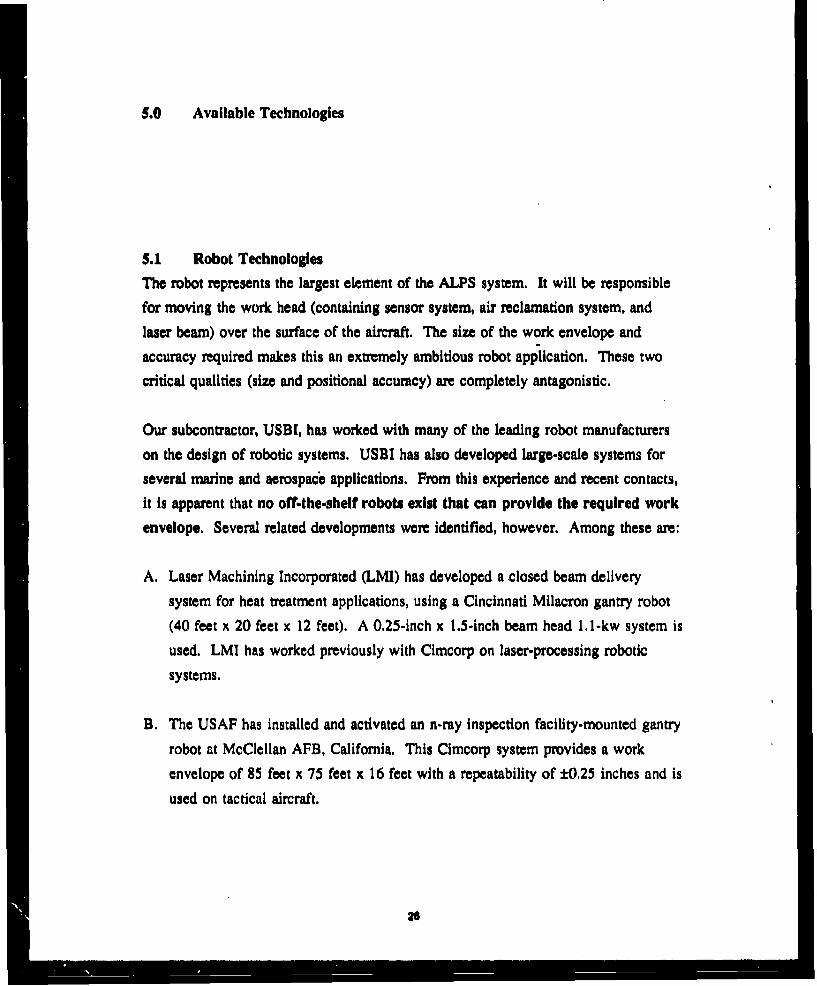
Robot concepts were evaluated on the basis of facility impact, schedule, flexibility,
technology risk and the ability to meet the s3 stem requirements presented in
27

Section 3.0. To quantify the evaluation, a weighted value was attached to each
requirement, as shown in Figure 5.1. The requirements were then compared to the
10 alternatives. If the concept did not meet the requirement, a score of "0" was
assigned. If the requirement was not applicable to the robot system, no score was
recorded. Weight values were summed by concept for every zero entry. The concept
with the lowest total score would theoretically be the best system.
Cost was not evaluated on a quantitative basis, but qualitative assessments were
made. Relative cost rank is noted at the top of the chart. Requirements not met by
the concept are noted in italics and parentheses in the following sections.
Combinations of the above system concepts are also discussed.
The most attractive system for the existing facility is the wheeled mobile vehicle with
a telescoping boom, It will accommodate the current floor in Building 2122 and will
not impact the facility. For a new floor in Building 2122, the selected concept would
be adequate, although other leading concepts would require reconsideration.
However, the selected concept is compatible for either scenario. The details of each
system are described in detail in the following section.
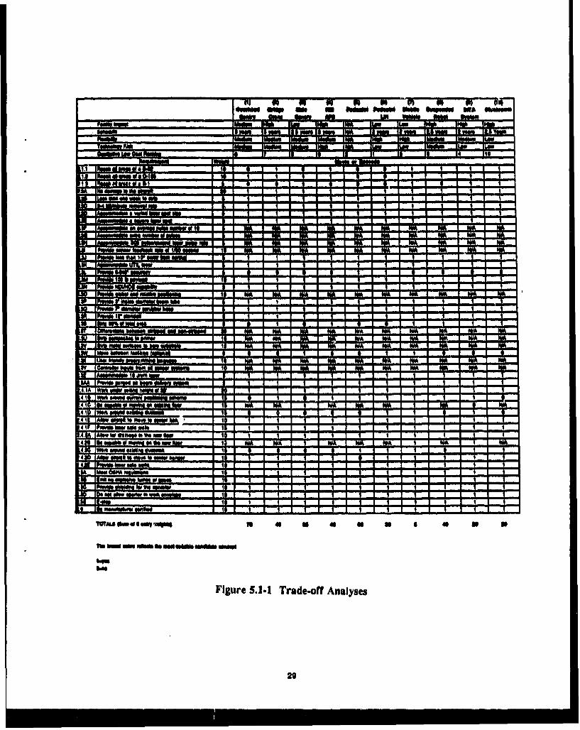
5.1.1 Overhead Gantry System.
This concept class representative is shown in Figures 5.1.1-1 and -2. This free-
standing system would utilize a telescoping or pivoting z-axis to move around the
aircraft. At the wrist of the z-axis, an additional arm would be attached for reaching
under the wings and fuselage. The gantry would provide a span of 150-160 feet and
a length of approximately 190 feet. The bridge section would be required to be self-
supporting across the work envelope width. At 20 foot centers, 9-10 legs would be
needed on each side. To allow for aircraft to be positioned in the middle hanger, no
legs would be permitted to support the end span rails.
Facility Impact. The existing floor in Building 2122 would need to be evaluated to
see if the loads delivered by the leg bases could be supported. The surface finish of
20
VI 44 a a a W N a - 84-*moo owp ow w Mom fob" "No *AWN"
WIN LE VamobINN IMA
FMLM am FAR*w IV Is is 14
FANARG" W"mmlý dlmllwlll - I Is
MOCI-Im I la Iml I I I**at I a 1 0 1 a I I a
Nos d"Im to ~ I m I I I I I I I II- fwwftftý I a I I I I I t I v
UR I MA WA
IA§NWAVAdMO
lpmwb owmw NAL I WAIPMWO Iin m I Ire. .4 .1
g Ig Imm
IAMWAWORMOW
lpo"m saw
MON IN a 8~ 1 1 1
lpow" NOWC11 loam I I I
IMAN "bm VA ""* smallimIPANW6 IF VAIN d~ Um mm I
[Pmvo ir I al5wofol too I alow" ---------
a MIND" Is
IWO wad WHISM is No WA I MA
Imm Womw Imul"
lumf WMMWMM mosion 1 00 1 WA I MA I OWMA
lAmowmudft 16 AWN I I I II pmwo NNW & I I I I
Wok OWMAWK seem I I IWok eaft ft"N"Mo I I98 on" 0 W4w*fMA I IW*A &WW $Nwo I I
AMW IMI 16 Woo fS MW Mk I IPwo iow No vmk IAl" ftow b W4 w ow Ilk on" 0 mow so " olm fty I W& I I I I "aWoo MWA ORWFM ONO" I a I I I I I I I
AIM SMQ ffi ONO to NNW
PwAft imm "m ME I I I
Moo 66MA mmkm
twombm"m
fOft 0 "A 41AWA10
IN ONO Oft ft Md S*" MOAN Mao
%ow
Figure 5.1.1 Trad"ff Analyses
29

o". .4
&l.I
Ho Wm *I. 4t' 1
.1 ~-90~ '~ T,* 1.1 1.% I *' .~.f.,...'V .
II
'.4'
4.~~~) ,2.A4.
-44 *....04 4'.!. e
>4 3 . ~ ~ rr f4 %. ~** t:'1~r i~r ,Itd IA
30
i2.1
irkj
:31

the current floor would require some modification for leveling purposes (the floor
level differs by approximately 1 foot from the north side to the south side). If a new
floor was installed in Building 2122, the necessary floor provisions could be made.
The existing duct work along the side walls of Building 2122 would interfere with
the gantry structure, reducing its width and/or height capability, The workable
ceiling height would limit the height of the gantry structure if a telescoping z-axis is
incorporated. The telescoping member requires space above the gantry structure of 5-
10 feet.
Schedule. Design, fabrication, and installation of this system into 3uilding 2122 is
projected at approximately 3 years. While gantry technology is quite advanced on a
small scale, large systems such as this do not exist. Significant design effort would
be required, long-lead itoms identified and fabrication activities started as early as
possible. Software development would require not only kinematic formulation but
would need to account for structural deflection across such a large span.
Flexibility. The system could provide other operations, such as NDI/NDE. The
system is not transportable between buildings.
Technology Risk. Some risk is associated with developing a system of this size.
Risk is reduced by the fact that the gantry's basic technology is already proven.
Beam delivery methods are also proven for gantry systems.
Meeting System Requirements. Non-compliance areas for this concept are as
follows:
a Aircraft - Owing to facility limitations caused by the ventilation duct work and
ceiling height, it does not appear that the nose and left wing tip of the B-52 or
the upper sections of the B-I tail could be reached.
, Process - The spans required would introduce a significant structural deflection
into the system. The accuracy requirement of 0.040 inch could not be met
32

without adaptive control (2.3L). Surface area percentage stripped would not meet
the 90% requirement. (2.3S)
Facility - B-52 positioning in the facility would require more time and effort
than is currently necessary, because of the additional structures along the walls
(2.4. 1 B). Facility duct work would interfere with the gantry system (2.4.1 D,
2.4.2C)
Qualitative Cost Issues. The cost of the structure is estimated to be higher than the'
cost of most of the other concepts. Facility modifications would be necessary
whether it be slight modifications in leg base areas or a complete new floor.
Final Analysis. The overhead gantry system is feasible, but the cost of the system
and its inability to reach all areas of the aircraft when positioned in Building 2122
make it unfavorable.
5.1.2 Facility Bridge Crane SystemA concept representative of this class is shown in Figures 5.1.2-1 and -2. This
system is similar to the gantry but would be integral to the facility walls for support
(similar to the Cimcorp System at McClellan AFB). This concept incorporates anenlarged industrial bridge crane spanning the 160' building width. Side rails are to
be supported by the facility structure and/or additional supports attached to thefacility walls. The bridge spans the rails similar to the gantry system. No end legs
are provided on either end. A telescoping or pivoting arm is used with an additionalarm mounted on the end for reaching under wings and fuselages.
Facility Impact. While no impact to the facility floor would be experienced, a
significant amount of facility modification would be necessary particularly to thewalls, From conversations with the facilities engineers at Tinker AFB, it appears that
modification to the facility structure is not feasible.
33

INIW., iiiii
34

/II
I,
p
* I
* U
j-
II'Ii
35
As in the gantry scenario, the existing duct work along the side walls of Building
2122 would interfere with the side rails, To raise the rails to the nec,',ssary height,the duct work would need to be relocated. If the rails were installed below the
existing duct work, the required work envelope would not be met.
Schedule. The time for design, fabrication and installation of this system into
Building 2122 is projected at approximately 3 years. A significant hardware design
effort would be necessary to expand on crafe technology. Major facility
modifications would also be necessary.
Flexibility. The system could provide other operations such as NDI/NDE. The
system is not transportable between buildings.
Technology Risk, There is moderate risk associated with developing a system of
this size. Bridge crane technology is established on a smaller scale but would have
to be expanded. Beam delivery methods would be similar to the gantry structure
routing.
Meeting System Requirements. Noncompliance areas for this concept are as
follows:
, Aircraft - The system could reach all areas of the aircraft except for the upper
portion of the B-1 tail.
• Process- The system can not meet the 0.040 inch accuracy requirement, again
because of the lengthy spans and inherent structural deflections.
* Facility - The floor issue does not affect this concept. Facility duct work would
interfere with the crane system.
Qualitative Cost Issues. The cost of the structure and facility modifications would
be higher than all other concepts. Modifications to the walls would be the major
contributor to the cost.
36
Final Analysis. While the system is feasible, the amount of facility modifications
necessary, the cost of the system and its incapability to reach all areas of every
aircraft make it unacceptable.
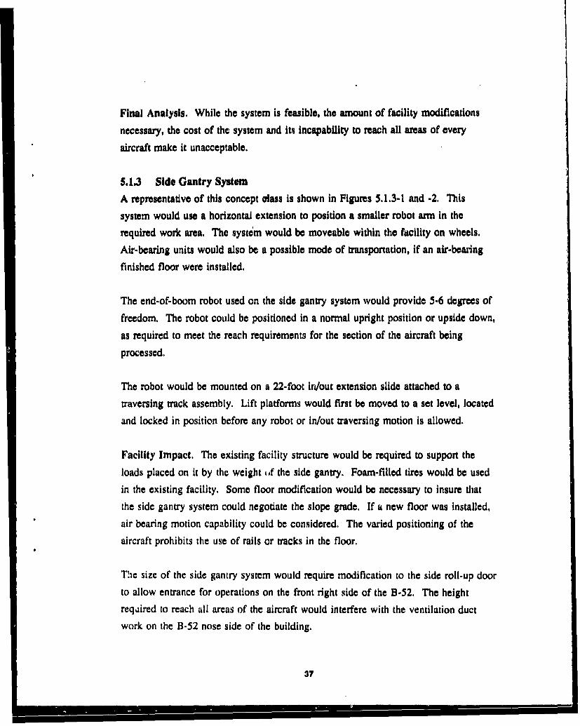
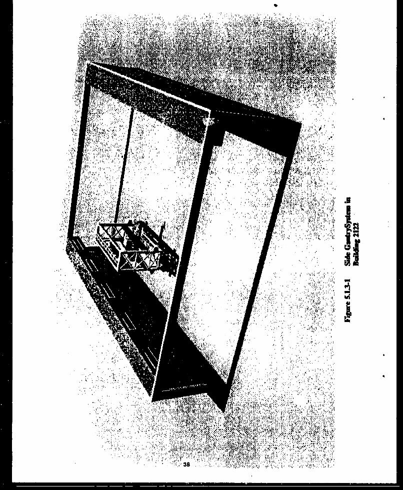
5.1.3 Side Gantry System
A representative of this concept class is shown in Figures 5.1.3-1 and -2. This
system would use a horizontal extension to position a smaller robot arm in the
required work area. The systim would be moveable within the facility on wheels.
Air-bearing units would also be a possible mode of transportation, if an air-bearing
finished floor were installed.
The end-of-boom robot used on the side gantry system would provide 5-6 degrees of
freedom. The robot could be positioned in a normal upright position or upside down,
as required to meet the reach requirements for the section of the aircraft being
processed.
The robot would be mounted on a 22-foot in/out extension slide attached to a
traversing track assembly. Lift platforms would first be moved to a set level, located
and locked in position before any robot or in/out traversing motion is allowed.
Facility Impact. The existing facility structure would be required to support the
loads placed on it by the weight of the side gantry. Foam-filled tires would be used
in the existing facility. Some floor modification would be necessary to insure that
the side gantry system could negotiate the slope grade. If a new floor was installed,
air bearing motion capability could be considered. The varied positioning of the
aircraft prohibits the use of rails or tracks in the floor.
The size of the side gantry system would require modification to the side roll-up door
to allow entrance for operations on the front right side of the B-52. The height
reqdired to reach all areas of the aircraft would interfere with the ventilation duct
work on the B-52 nose side of the building.
37
RIM, I'l
v~~~ ~ ~ t9VL1!1 11:.:K o :
frI it Ii
" ' " ...........
~~'WI,;: k7AtI.
39

Schedule. The activation time period for this system is projected at 2-1/2 to 3 years.
Being smaller than the previous two concepts and having a lower facility impact
reduces the necessary activation time.
Flexibility. The system could provide other operations, such as NDI/NDE. Under
tow or self-power, depending on the design, the system could move between facilities
(tre version).
Technology Risk. There is some risk associated with this concept, as it is not used
on a smaller scale and would require increased design effort, The required reach is
reduced, however.
Meeting System Requirements. Noncompliance areas for this concept are as
follows:, Aircraft - It does not appear that all surface areas of the aircraft could be
reached. Some thought would have to be given to moving around the B-52. The
side gantry system might have to be moved outside the building to reenter
through a side door. If the system were small enough to fit under the existing
duct work, then it would not be large enough to reach all areas.* Process - An accuracy of 0.040 inches can not be met by the system when
considering the telescoping extension. The off-the-shelf pedestal robot on the
end of the boom can meet the requirement, however. The surface area
requirement of 90% cannot be met, and the system would probably not fit around
the current positioning scheme.
• Facility - It does not appear that the system would accommodate the existing
duct work.
Qualitative Cost Issues. The system would cost less than the first two concepts,
because of its reduced size and'lessened facility impact.
40

Final Analysis. The system is feasible. However, the side gantry height
requirement, slight impact on the facility and process positioning scenarios make it
difficult to accommodate.
5.1.4 Hill AFB Type System
A representative of this system, sirilar to the Hill AFB installation, is shown in
Figures 5.1.4-1 and -2. This system would provide positioning of two smaller robot
arms by two larger SCARA (Selective Compliant Adaptive Robotic Arm) type arms,
Significantly longer reaches would be required for this system (on the order of 75
feet). The two larger arms would move the length of the building on tracks.
Facility Impact. The facility impact would be significant for this system. If the
facility ventilation duct work is relocated, the top track can be located at workable
ceiling height level. If the duct work is not relocated, the upper track would be
located immediately underneath. With the existing floor, the two robot systems
would not be identical (i.e,, the floor elevations differ ftom one side of the facility to
the other).
Schedule. Design, fabrication and installation time for this system into Building
2122 is projected at approximately 3 years.
Flexibility, The system could provide other operations, such as NDI/NDE. The
system is not transportable between buildings.
Technology Risk. The system purchased by the USAF has established the basic
technology. The expanded reaches demanded by this application would increase the
risk substantially, however,
Meeting System Requirements. Noncompliance areas for this concept are as
follows:
41

dii
42

4 4
II

9 Aircraft - The upper portion of the B-I tall could not be serviced if the system
is installed below the existing duct work.* Process - The 0.040-inch accuracy could not be met by the entire robot system.
0 Facility - The system would interfere with facility duct work if it was to meet
the work envelope requirements.
Qualitative Cost Issues. Facility modifications and structural costs make the system
one of the more costly of the alternative concepts.
Final Analysis. While this concept is ranked In the upper half, its substantial cost
would prove prohibitive. The long reaches necessary would also prove to be a
technical challenge.
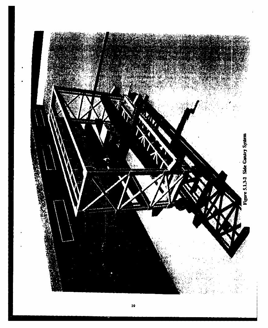
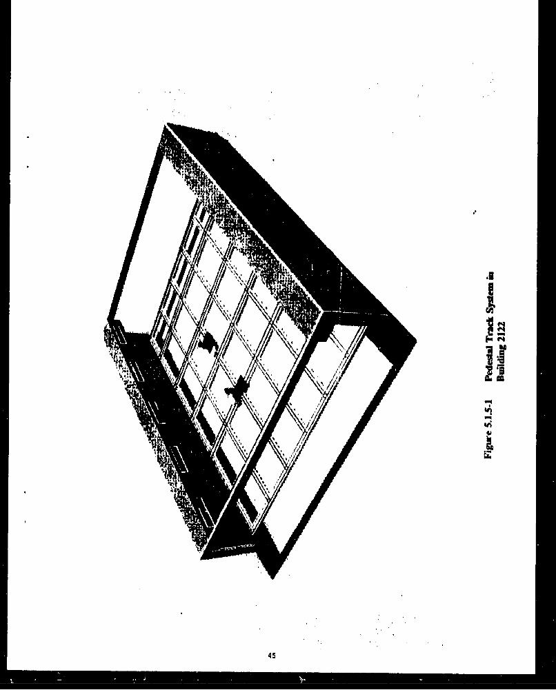
5$1. Pedestal Robot System
This system would incorporate multiple off-the-shelf pedestal robots positioned on
tracks around the aircraft around the outside shape of the various aircraft (preferred)
or in a grid pattern. Clearly, this concept would not meet the reach requirements
necessary. Even if the reach of the largest off-the-shelf pedestal robot was tripled, it
would barely meet the necessary reach requirement. For this reason, the track-
mounted pedestal robot alternative was excluded from further evaluation. Several
robot manufacturers have been contacted about increasing the reach of their standard
robots, None feel that this redesign is feasible. A symmetric grid track approach is
shown in Figures 5.1.5-1 and -2.
3.1.6 Pedestal Robot Lift System
To investigate the use of pedestal robots, the concept of a pedestal robot on a mobile
lift mechanism such as a scissor, lift or hydraulic cylinder-lift platform was evaluated.
A sketch of a representative concept is shown in Figures 5.1.6-1 and -2.
Oili
45

Pm
lI
......... 4

I a. I
47

p
I
Ii0'
V '48

Facility Impact. No facility impact would be encountered by this concept. kloor
slope grades would need to be evaluated.
Schedule. The integration time for a pedestal robot and a scissor-type lift (or a
platform-type lift) is projected at 2 years.
Flexibility. The system could provide other operations such as NDI/NDE and be
transportable between facilities.
Technology Risk. These two items have not beca integrated in the past.
Individually, their risk is low; however, USBI has performed a preliminary design
activity on this type of concept and found stability to be an issue.
Meeting System Requirements, Non-compliance areas for this concept are as
follows:0 Aircraft - The system can not reach all areas of each of the aircraft. The system
would not be capable of reaching completely under the wings or fuselage.
n Process - The system can not strip 90% of the total surface area of the three
aircraft combined.
* Facility - All facility requirements are met by the system.
Qualitative Cost Issues. The hardware cost of the system would be one of the
lowest.
Final Analysis. This is a concept that requires further attention. The major
drawback of the system is its reach limitations,
5.1.7 Mobile Vehicle System
This system would utilize a standard flight line transport tug (a more stable base)
with a telescoping boom to position the work head around the aircraft, This concept
representative is shown in Figures 5. 1.7- 1 and -2.
49

' T'
"k-'rý I~~l.Rk I' Ot'A. gtt
, iu ,m, k _ V
'41

-Ai'
U.~ 4 Q~ N
W"Vi ' , ~ a.4 1 '4 w' ~ >t.¶04:' .
4' ~ ~ 4 . 4 Ati
VI.
t4
it, I'.
SIM .14
Facility Impact. No facility impact is associated with this concept. The floor slope
grade would require evaluation.
Schedule. System design, fabrication and installation time are projected at
approximately 2 years.
Flexibility, The system could provide other operations such as NDI/NDE and would
be transportable between facilities.
Technology Risk. From the integration standpoint, there is some risk associated with
this concept; however, all components to be integrated are based on existing
technology,
Meeting System Requirements. Noncompliance areas for this concept are as
follows:"* Aircraft - All aircraft reach requirements are met by this system."• Process - The accuracy requirement of 0,040 inches cannot be met by the
system."• Facility - All facility requirements are met by this systtvm.
Qualitative Cost Issues. The cost associated with this system would be neer the
bottom of the concept list.
Final Analysis. This system concept class is not only feasible, but is evaluated as
the best of the alternative candidates.
5.1.8 Suspended Robot (NiST-type) System
This system would incorporate technology developed at the National Institute of
Standards and Technology, as pictured in Figures 5.1.8,-l and -2. A pedestal robotwould be suspended by cables from a moving platform.
82
~~rI.
_ _ _ 53

10
.54

NIST's Robot Crane Technology Program developed kinematically constrained,
dynamically stabilized robot cranes capable of lifting, moving, and positioning heavy
loads over large volumes, capable of supporting fabrication tools and the inspection
of large size and difficult-to-reach structures.
Facility Impact. This option would require a significant facility impact, similar to
the crane concept (section 5.1.2).
Schedule. Design, fabrication and activation time for this system is projected at
2-1/2 to 3 years.
Flexibility. The system could provide other operations such as NDI/NDE but would
not be transportable between buildings.
Technology Risk. There is risk associated with this concept, The basic technology
has been proven at NIST, but only under laboratory conditions,
Meeting System Requirements, Noncompliance areas for this concept are as
follows:
"* Aircraft - The system would not be able to reach all areas of the B- 1, because of
the facility duct work location,
"* Process - An accuracy of 0.040 inches could not be met.
* Facility - Facility duct work would interfere significantly with crane operations
and/or limit the work envelope.
Qualitative Cost Issues. The cost of the system would rank among the top of the
concept entries,
Final Analysis. While the technology appears well suited for the application, the
facility does not lend itself to such a configuration.
LO5

S.1.9 InTA System
This system would consist of InTA's design as proposed to the Navy, with a
modified reach capability. InTA's system uses SwRI developed a:-m similar to the
system to be installed at Hill AFB. The system would be mounted on an air-bearing
platform and follow a soft wire for each specific aircraft type on the floor. The robot
ann provides a reach of 22.5 feet and is counterbalanced by the weight of the laserunit located on the air-bearing platform. A conceptual drawing is not available.
Facility Impact. The system, as configured, will not operate in the existing facility.
A new air-bearing surface is required.
Schedule. The system currently being designed for the Navy is scheduled for
activation in 3 years. Based on knowledge gained in the Navy program, this system
could probably be installed in 2 years.
Flexibility, The system could provide other operations such as NDI/NDE but is not
capable of moving between facilities.
Technology Risk. At the present, there is a significant amount of risk associated
with the project. Based on the development of the Navy system, the risk could be
reduced.
Meeting System Requirements. Noncompliance areas for this concept are as
follows:
"* Aircraft - The system could meet all aircraft reach requirements.
"* Process - The accuracy requirements cannot be met.
"• Facility - The system cannot operate in the existing facility.
Qualitative Cost Issues. The cost of this system is in the bottom third. The Navy's
purchase price is reportedly under $10,000,000.
56

Final Analysis. The system is among the top candidates; however, its inability to be
used in the existing facility severely limits it.
5.1.10 Mushroom SystemThis system is similar to a USBI/AKR Robotics team concept selected by McDonnell
Douglas Aircraft in Tulsa, Oklahoma. A 6-dgree-of-freedom robot is mounted to ascarn positioner. The positoner Is raised and lowered on a cylinder which isinstalled in the facility floor. This system is shown in Figures 5.1.10-1 and -2.
Facility Impact. The system would significantly impact the floor of the facility. A
new floor would have to be installed and large pits provided for the cylinder and
drive systems.
Schedule. System installation and activation would require 2 to 2-1/2 years.
Flexibility. The system could provide other operations such as NDI/NDE but is not
capable of moving between facilities.
Technology Risk. Risk for ,his system would be reduced because of the installation
of a similar system for McDonnell Douglas.
Meeting System Requirements, Noncompliance areas for this concept are as
follows:. Aircraft - Multiple robots could meet all aircraft reach requirements. A single
system, however, could not meet the reach requirements.a Process - The accuracy requirements cannot be met.SFacility - The system cannot operate in the existing facility, Systems would also
need to be positioned so that an airplane could move to the center hangar,
, I I5l

MIER
j58

, LI
Ii
*1*5*

Qualitative Cost Issues. The cost of this system would be high because of the
facility impact and the number of robots required.
Final Analysis. The inability of the system to be used in the existing facility mid the
number of systems required severely limit its feasibility.
5.1.11 System CombinationsSome combination of the previously described systems should be evaluated. For
example, one of the overhead concepts (5.1.8) can be used in conjunction with a
mobile pedestal robot (5.1.6). Clearly, the advantages of such a system are:
0 Reduced reach requirements for the robot systems
* Use of standard pedestal robots for both systems.
Disadvantages for this type of system would include:
a Facility impact associated with the overhead system
* Cost of the two laser systems over the cost of one system.
Because of the facility impact and cost of the additional laser systems, it does not
appear that any hybrid system would meet the near-term requirements of the USAF
for Tinker AFB. However, in a new facility this might prove to be a favorable
approach.
60

5.2 Laser Technologies
5.2.1 Background Information • Materials Processing.
The laser is one of the most significant and versatile technologies of the second half
of this century. Lasers ranging from tiny semiconductor devices to giant industrial
systems are used in a wide variety of applications in manufacturing, R&D, medicine,
telecommunications, computer peripherals, defense, and entertainment.
Materials processing with lasers can be more flexible, faster, and more precisely
targeted than with conventional techniques. In some situations, laser processing is
economically advantageous -- it increases productivity and product quality and
reduces processing cost. In other situations, lasers allow new processing tasks that
are not possible by other means. Together with robotics and automated process
control and inspection, lasers can enhance flexible manufacturing and maintenance
systems.
About 17,000 industrial laser systems are installed worldwide, with over 3,100
systems Installed in 1988 (Table 5.2.1). The laser component itself typically accounts
for only one-sixth of the value of the total system, which includes the means of laser
beam delivery, parts handling, control, and monitoring.
The automotive industry, one of the first mass-production industries to use laser
technology, accounts for about one-quarter of laser materials processing applications.
The principal applications are welding, cutting, and drilling. The aerospace and
electronics industries each account for about one-sixth of the application, and the
remainder ranges across numerous industries, from garment making to shipbuilding.
Factors that have limited the growth of lasers are:
The high initial costs of large laser installations
Uncertainty of the costs, performance, and benefits of laser technology relative to
well-established alternative technologies
Continuing advances in competitive materials processing technologies.
61

Table 5.2.1 Installed Base and Sales of Industrial La5ers (1988)
I-Units Total Installed
Carbon Dioxide 1,900 (60%) 8,800 (52%)
Neodymium/YAG 1,200 (38%) 8,000 (47%)
Excimer 60 (2%) 200 (1%)
Total 3,100 17,000
Lasers are sources of electromagnetic radiation in the optical (ultraviolet, visible, and
infrared) igions of the spectrum. Conventional light sources produce radiation by
spontaneous (random) emission. In contrast, lasers generate their output by
stimulated emission within the lasing medium, which may be a solid, a liquid, or a
gas. ,'onfined withi, s reflective resonator, the radiation is amplified by successive
passages through tme medium and emerges as a powerful, concentrated, cohert..:t
beam.
Excitation of a gas-lasing medium is usually achieved by initiating an electrical
discharge within -ie laser resonator, while solid and liquid (dye) media are "optically
pumped" by means of high-intensity lamps or a secondary laser. In semiconductor
lasers, the recombination of holes and electrons in the semiconductor material gives
rise to the coherent optical emission.
The laser output beam has three main attributcs that are valuable in industrial
processing:
"* The beam's high radiance (brightness) and the use of focusing optics together can
produce very high levels of irradiance (power density) at the workpiece.
"* Its directional nature permits remote, flexible, localized, and efficient processing.
" Its monochromaticity (narrow spectral bandwidth) allows strong yet selective
absorption into the target material.
62
Although conversion efficiencies from electrical input to optical output are neverhigh, the entire output can be applied to the process, yielding overall process
efficiencies that are often competitive with those of conventional techniques.
Laser-Material Interactions
Most industrial laser processes are, thermal, that is, they depend on the high
temperature generated by absorption of the laser beam into the material being
worked. The irradiance (power density) and interaction time determine the
temperature and the resulting effect (Figure 5.2.1). Progressively higher temperatures
are required for surface modification, welding, cutting, drilling, and ablation.Ablation is the almost explosive removal of small quantifies of material by pulsed
laser radiation of high-peak power and short duration, so that material is vaporized
and removed without harming the surrounding area.
Laser output power does not correlate directly with the temperature achieved because
temperature is also affected by the incident beam area (spot size) and the processing
speed (when there is any relative motion between the beam and the material, as in
cutting, welding, and paint stripping). Very high power lasers are being used tospeed up processing (thereby increasing productivity), rather than to achieve even
higher temperatures.
Lasers can interact photochemically with organic substrates, as opposed to thermally.
The incident laser energy interacts directly with the molecular structure of the
material, breaking molecuLar bonds and inducing chemical change. Photochemical
effects depend on total absorbed energy, not on energy rate. These effects require
radiation at low wavelengths (in the ultraviolet) where the energy of the individual
photons is relatively high. UV lasers are being used for the rapid curing of acryliccoatings, for ablative marking, and for hole drilling in printed circuit boards,
63

Irradiance (W/m 2)
1015
Ablation*::
10 "12 1 . 1 . 1 .10
io~Welding:'.
106 modlicflcton
10-12 10-9 10.6 10.3 1 103
Interaction Time (seconds)
Source: Cambridge Consultants Ltd.
Spectrum. Advanced Materials
Figure 5.2.1 Irradiance Levels and InteractionTimes of Different Types of Laser.Material Interactions
64
Industrial Laser Processes
The principal industrial laser processes are cutting, welding, marking, drilling, and
surface modification. Although different than laser paint stripping, much of the
technology is similar and is useful in considering available technologies.
Cutting
Laser cutting offers high accuracy, precision, and process speed, as well as minimal
part distortion and the ability to cut intricate shapes and to reprogram patterns *rapidly. Lasers can suc ,•ssfully cut many metals, including steel, stainless steel,
titanium, and thinner sections of aluminum and copper. Lasers can also cut many
nonmetals, including composites, plastics, paper, wood, rubber, leather, and certain
low-expansion glasses. Cutting piecision of 0.01 mm is achievable with lasers,
although precision is sometimes limited by the work.handling system and by thermal
distortion in the workpiece rather than by the laser itself.
Organic matrix composites and engineering plastics are increasingly replacing metals
in many applications. Such materials are generally difficult to cut by conventional
methods but can be cut accurately and productively using lasers. Complex contoured
structures can be processed by combining the laser beam delivery system with a
multiple-axis table or gantry arrangement.
Welding
Lasers can weld steel plates mrore than 25 mm thick in a single pass. High
processing speeds, low distortion (which is important with thinner materials), narrow
heat-affected zones, and strong welds in many metals are among the advantages of
laser welding. In some materials, the mechanical properties of the weld can surpass
those of the base ma rial. Laser welding is particularly advantageous for materials
such as magnetic alloys that are difficult to join by conventional welding techniques,
An inert gas flow shields the beam-focusing optics from sputter, removes the plasma
(generated by metal-laser interaction) that would reduce the efficiency of energy
! 65
coupling into the weld, and prevents oxidation of the molten metal. Like laser
cutting, laser welding often requires very accurate motion systems, although seam
tracking is often used in large-volume production where the manufacturing tolerances
do not position the joint line consistently. Filler wire is sometimes used to increase
the tolerance of laser welding to gap width.
The feasibility of using lasers for joining composites is under investigation by the
Edison Welding Institute and other organizations. The automotive industry, among
others, is already using lasers for cleaning the surface of composites to enhance
bonding.
Marking
Laser marking technology is widely established globally. Two basic laser-marking
techniques in use are mask marking and spot scanning. In mask marking, an
expanded laser beam is projected onto the substrate through a stencil mask that
defines the pattern to be marked. Commercially available systems using pulsed lasers
can produce up to 50 marks per second in this way.
In spot scanning, a focused laser beam spot is scanned with a galvanometer mirror to
"write" directly onto the surface of a material. Unlike mask marking, where a change
of mask is needed to change the mark, spot scanning can be computer-controlled to
produce an infinite variety of patterns.
Laser marking relies on a change of state at the substrate surface and is similar to
laser paint removal. Pulsed Nd.YAG lasers are used most often, although CO 2 lasers
are also employed. UV-emitting excimer lasers can also produce marks with high
visual contrast and high resolution on many materials. Lumonics (Canada), now
owned by Sumitomo Heavy Industries (Japan), pioneered the development of markingwith excimer lasers. With some organic materials, excimer laser marking is a
photochemical process rather than a photothermal one. Excimer ablation marking can
L 66

be particularly useful with brittle materials, such as glass, because of the absence of
thermally induced stress.
Similar laser-based techniques are also used for micromachining, surface etching, and
semiconductor fabrication. Like ablation marking, these techniques all involve the
controlled removal of minute amounts of material.
Drilling
The use of pulsed lasers to form small holes with great precision in thin-gauge metal
is now well established. Flexibility, hole quality, and speed are the laser's main
advantages. Recent improvements in laser design (especially beam shape) have
allowed taper-free drilling even of thicker materials. Hard, brittle materials (such as
ceramics and sapphire) that can be difficult to drill by other techniques can be laser.
drilled successfully. The noncontact nature of lavir drilling greatly reduced part
distortion and eliminates the part contamination and drill-bit wear, breakage, and
replacement that occur with conventional drilling.
Improved techniques for drilling holes as small as about 50 microns in diameter are
being developed by Laser Fare and other companies. Such techniques would offer
considerable advantages over conventional chemical etching by permitting faster and
more accurate processing, which would be especially valuable in the aerospace
industry for fabrication of critical engine components.
Surface ModificationSurface modification by lasers includes surface hardening and surface alloying. In
surface hardening, a coating may need to be applied first to increase the laser beam's
absorption. The laser energy heats the surface to above the phase-transformation
temperature. Because the heating effect is localized, rapid quenching occurs by
thermal diffusion into the surrounding unheated material. In ferrous metals, shallow,
localized layers of hardness can thus be produced with minimal amounts of energy.
67
Laser surface alloying with cobalt, nickel, ferrous alloys, or carbides is used to
improve corrosion resistance of surface wear characteristics. As with other laser
surface modification processes, the uniform energy distribution required can be
achieved by multimode laser beams, beam scanning, or specially designed optical
beam integrators (which convert the inherent Gaussian distribution of energy into a
more uniform one).
The principal benefits of laser surface modification are low distortion, reduced energy
input, localized processing (restricted to those areas subject to greatest wear), and
high production rates. Furthermore, this technique often eliminates the need for
subsequent finish grinding.
Other Industrial Applications
In addition to the various materials-processing tasks reviewed above, in which the
laser causes a permanent physical change in the target material, lasers of lower power
are used for sensing, measurement, and inspection. These functions include
interferometry; optical sensing of position, vibration, and temperature; optical
profiding of complex shapes; machine vision; holographic recording of engineering
structures; and chemical analysis by laser-based spectroscopy and fluorescence
measurements. The key difference is that in these applications, the laser beam is
used as an information carrier, as opposed to an energyi zarrier in materials
processing.
Increasingly, however, combinations of low-power and high-power lasers are being
used in the same process. Thus, optical monitoring by a low-power laser can provide
feedback control of a task being performed by a high-power processing laser. Also,
many high-power industrial laser systems incorporate a low-power visible beam
(typically from a helium-neon laser) as an alignment aid.
The use of lasers for material synthesis and modification is also being investigated.
In laser photosynthesis, the laser beam energizes a photochemical reaction (as
68

opposed to effecting only a physical change). For example, a process developed at
the Massachusetts Institute of Technology uses a I80-W continuous wave CO2 laser
to synthesize ceramic powders of very high purity and uniform submicron particle
size. This process eliminates grinding, which is a troublesome source of
contamination in conventional methods. Ceramic products made from these powders
have superior mechanical properties and fewer defects than those made by
conventional means.
Types of Industrial Lasers
Of the many different types of lasers that have been developed in the 30 years since
laser action was first demonstrated in ruby, just two perform the vast majority ofindustrial laser processes: the C02 gas laser and the Nd:YAO solid-state laser
(Table 5.2.2). Excimer lasers are much more expensive -- their capital costs are on
the order of $1,000/W compared with $100/W for C02 and $150/W for Nd:YAG.
Use of excimer lasers in materials processing is relatively limited at present but is
expected to grow in specialized high-precision applications.
Carbon Dioxide LasersThe C02 laser is established as the workhorse of industrial laser processing, largely
for cutting, welding, and surface modification. C02 lasers offer high reliability withoutput power ranging from 500 W to 10 kW, The CO2 laser utilizes a mixture of
gases comprising C02 (the lasing medium) and usually two other gases, nitrogea andhelium, to enhance efficiency. An electrical discharge within the gas mixture,
produced by either direct current or radio frequency energy, initiates and sustains
laser operation. C02 lasers emit in the iniared (at 9-11 microns, with the strongestline at 10.6 microns).
Sealed-tube lasers can be used for power outputs up to about 50 W, but gas
circulation must be used for most industrial applications, where up' to severalkilowatts are often required. Earlier slow-flow systems have given way to either
transverse-flow (TF) or fast-axial-flow (FAF) systems, both of which permit
so

Table S.2.2 Major Types of Lasers Used in Industrial Materials Processing
Type of Laser
Process CO2 Nd:YAG Excimer
Cutting X X
Welding X X
Marking X X X
Drilling X
Surface
Modification X X
Paint Stripping X X
high-output power to be generated from relatively compact resonators. However,
recent research at Heriot-Watt University (U.K.) suggests that more-compact sealed-
tube or slow-flow systems of high power may yet become feasible.
Neodymium YAG Lasers
By contrast, Nd:YAG lasers are solid-state devices containing a crystal of yttrium
aluminum garnet doped with neodymium ions to about 1%. Excitation (pumping) is
accomplished optically, using high-intensity white-light lamps positioned around the
crystal and focused on it. Emission in the near-infrared (at 1.06 microns) enables the
output beam to be transmitted through optical fibers, permitting more flexible beam
delivery and multiple workstations with rapid switching between tasks. Simultaneous
spot-welding on the same component can also be carried out. Nd:YAG lasers may
be operated in either continuous or pulsed mode, where peak powers of several
megawatts are achievable, but maximum average or continuous powers are lower--
currently just over I kW.
70

The main applications for Nd:YAG lasers are drilling, marking, and micromachining.
Nd:YAG lasers' high-peak power makes them suitable for intermittent processes such
as drilling, whereas CO2 lasers' high-average power makes them useful for
continuous processes such as cutting and welding. Because of their shorter
wavelength, Nd:YAG laser beams can be focused more narrowly than CO2 laser
beams, thus permitting more accurate micromachining. In pulsed mode, Nd:YAG
lasers can process aluminum and copper, something that can be difficult with CO2
lasers because the surface reflectivity at 10.6 microns is high and because heat is
transferred rapidly away from the point of impingement.
Significant advances in beam quality (through resonator design) and system reliability
(through longer lamp lifetimes) have made it possible to drill deeper holes and reduce
the sun-ounding heat-affected zone. Technical problems in growing larger crystals
and in heat dissipation are the main limitations to achieving greater output power,
although multiple crystals can be used to increase the volume of the active medium.
Safety is seen as more of a problem with Nd:YAG because the threshold of eye
damage at its wavelength is lower than with other types of lasers. Although
continual improvement in Nd:YAG technology will strengthen this sector of the
market, encroachment into the CO2 lasers' preserve of high-speed metal cutting and
welding is unlikely.
Excimer Lasers
The lasing medium in excimer lasers is a rare-gas compound, such as argon fluoride,
krypton chloride, or xenon fluoride, that can exist only in an excited state (hence thename "excited dimer" or "excimer"). Excimer lasers' short pulse duration and high-
peak power permit surface ablation that is highly controllable and causes no thermal
damage to adjacent material. The very short emission wavelengths -- in the
ultraviolet, which most materials absorb heavily -- provide much finer resolution than
is possible with other lasers. In organic materials, excimer lasers can produce
photochemical rather than photothermal effects,
71

The output beam from excimer lasers has a larger area and is more divergent than
beams from other industrial lasers. This feature is advantageous in through-mask
processing but limits focal-spot applications. Excimer lasers would be economically
competitive only in specialized high-precision applications, not in bulk processing
tasks.
Currently, excimer lasers are used primarily for exploratory or "mission" sales for
assessing and developing new technologies. Emerging application areas are in
micromachining, marking small parts at high speeds, photochemical processing ( as
in semiconductor fabrication), and hardening and annealing very thin layers.
In our companion study (WL-TR.91-4025), Arthur D, Little has shown that excimer
lasers may be successfully used to strip paint from composites. Strip rates are
currently low, and the high cost of excimer lasers will limit their use in this area.
Other Types of Lasers
Other types of lasers are used occasionally for specialized processing applications
that require relatively low power but specific emission wavelengths for very selective
absorption by the target material.
Ruby lasers are crystal lasers that are optically pumped in a similar way to Nd:YAG
lasers and produce a red output beam at 0.694 microns. They are suitable for certain
high-precision drilling operations, but their low-pulse repetition rate of about 1 Hz
limits their usefulness.
Carbon monoxide (CO) lasers are heing investigated for materials processing.
Their output, which lies between those of Nd:YAG and CO2 lasers, is absorbed more
strongly in some metals than CO2 lasers and can be delivered via optical fiber, as can
the Nd:YAG's output. CO lasers offer greater output power and efficiency than CO2
lasers, although cryogenic cooling of the laser cavity is required for optimum
performance.
72

Fre-eelectron lasers (FELs) are currently at the research stage. They produce an
intense, coherent output through the interaction of an electron beam with an optical
beam in a magnetic field that varies rapidly along the region of interaction. The
FEL's main advantages over conventional lasers are tuneability over a wide range
(and hence, versatility) and higher efficiency. The FEL's disadvantages include very
high system costs (in the millions of dollars) large size, and limited availability--only
about 10 FELs exist in the Unites States at present.
In the United States, the U.S. Department of Defense's Strategic Defense Initiative
sponsors most of the R&D on FELs. In the United Kingdom, the University of
Liverpool is developing a more compact FEL with emission in the far-infrared and
microwave regions but with the potential for a lower wavelength (near that of the
CO2 laser).
Suppliers
About 1,500 companies participate in the industrial laser business worldwide.Roughly a thousand of them are contract laser processors (job shops), with
approximately 400 in the United States and 300 each in Europe and Japan. Of the
over 300 major equipment suppliers, 40 manufacture only the lasers, 70 make both
lasers and complete processing systems, and 200 are system integrators. System
integrators buy lasers from vendors on an OEM basis and incorporate them into their
own systems for sale to end users.
Table 5.2.3 lists the world's principal industrial laser manufacturers, including
suppliers of total systems, but excluding system integrators that do not manufacture
lasers themselves. Other selected participants are listed in Table 5.2.4. The
proportion of major laser system installations developed and supplied by system
integrators is generally greater in Europe than in the United States.
73

Table 5.2.3 Principal Manufacturers of Industrial Laser Devices and Systems
Base Laser Devices LaserCompany (Parent or Full Name) Country C02 Nd:YAG Systems
Excimer
Alumor Laser Israel X
Amada Japan X X
Coherent General USA X X X
Electrox UK X
Ferranti UK X X
International Laser Machines(Cincinnati Milacron) USA X X X
Lambda Physik W.Germany X
LISA (Laser Industries S.A,) France X
LMI (Laser Machining, Inc,) USA X X
Lumonics (Sumitomo HeavyIndustries, Japan) Canada X X X X
Matsushita Industrial Equipment X(Matsushita Electric Industrial) Japan X
Mitsubishi Electric Japan X x
NEC Electronics (NEC) Japan X
Quantronix USA X
Raytheon Laser Products(Raytheon) USA X X X
Rofin-Sinar (Siemens) W.Germany X
Trumpf W.Germany X X
United Technologies USA X X
XMR (Amoco) USA X
74

Table 5.2.4 Selected Industrial Laser Manufacturers
Laser Type
Company (Parent or Full. Name) Base Country C02 Nd:YAG Excimer
Aldron Sources (Lectra Systemes) France X
Advanced Laser Systems USA X
Apollo Lasers (Patlex) USA X
Baasel Lasertechnik WGermany X
CBL Optronics Belgium X
Control Laser (Quantronix) USA X
Diahen Japan X
Electro Scientific Industries USA X
Fanuc Japan X
General Systems Research Canada X
Haas Laser W.Germany X
Hitachi Japan X
Integrated Laser Systems UK X
Lasag Switzerland X
Lasercut Switzerland X
Laser Dynamics Australia X
Laser Electronics Australia X
Laser Materials Processing Switzerland X
Laser Nucleonics USA X
Laser Photonics USA X
Lasertechnik (Esab Held) W.Germany X
Laser Valfivre Italy X X
75
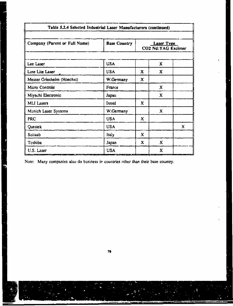
Table 5.2.4 Selected Industrial Laser Manufacturers (continued)
Company (Parent or Full Name) Base Country Laser TyveC02 Nd:YAG Excimer
Lee Laser USA X
Line Lite Laser LISA X X
Messer Griesheim (Hoechst) W.Germany X
Micro Controle France X
Miyabhi Electronic Japan X
MLI Lasers Israel X
Munich Laser Systems W.Germany X
PRC USA X
Questek USA X
Soitaab Italy X
Toshiba Japan X X
U.S. Laser USA X
Note: Many companies also do business it' countries other tha, their base country.
76

Technology Trends
Significant trendz for industrial laser technology over the next 5 years include, the
following:
0 Parts and complete products being designed specifically for laser processing to
exploit laser technology's benefits fully, rather than simply using lasers as a
replacement for conventional manufacturing techniques;
0 A greater role for systems engineering, leading to more advanced laser processing
and more effective implementation as part of the production process;
0 More compact high-power CO2 laser systems, through improvements in resonator
design and gas-flow technology;
* Increasing use of sealed-tube CO2 lasers at medium power (100-500 W).0 Very high power (as much as 25-50 kW) CO2 systems, primarily for high-speed
welding but also for cutting and surface modification;
High-power (up to 2 kW) Nd:YAG systems with multiple crystal assemblies that
have superior drilling capabilities and can perform some of the cutting and
welding tasks currently done by CO2 systems;
0 Greater use of fiber delivery systems for Nd:YAG lasers, to increase processing
flexibility and provide more freedom in the integration of laser systems in
processing lines;
0 More sophisticated beam delivery systems for CO2 lasers, including beam-
shaping and scanning systems, for optimal coupling of the laser radiation with the
workpiece material;
77
" Multiple workstations from higher-power single laser units, using both Nd: YAG
(with fiber delivery) and CO 2 systems;
" Greater reliability and better beam quality at higher power, through improvements
in resonator ana system designs, as well as in critical components, such as
flashlamps, output couplers, and gas-circulation units.
S.2.2 Recent Laser Paint Stripping Activities. As previously noted, Warner
Robins Air Logistics Center (WR-ALC) was the lead site for a laser paint stripping
program bid on by InTA, Avco, and Battelle among others. The contract was not
awarded.
InTA has received the authority to proceed on the two robotic depainting systems for
Navy fighter-size aircraft laser depainting. InTA has five subcontractors , including
Grumman, United Technologies Industrial Lasers (UTIL), and SwRI. The laser is a
6 kw-pulsed CO 2 system developed by UTIL, providing a 250,000-W peak during
each pulse. Dr. Paul Lovoi of InTA states the optimal paint stripping laser should be
in the 5-10 KW range and that despite the research into excimer lasers, CO 2 lasers
are the optimal method. A sealed beam tube delivery system with mirrors is used,
The laser provides 5 J/pulse to remove paint at a rate 3 ft 2 per minute (180 ft2 per
hour). One hundred fifty to two hundred fifty microinches of paint are removed per
pulse. At 1000 pulses per second (5 kw to the surface, I kw lost power), 1000 Hz is
delivered per pass (one pass per second) over 1 square foot. Using 200 microinches
of paint removed per pulse, 5 pulses will remove one mil of paint. Based on a
thickness of 4.2 mils of paint for a typical aircraft coating thickness, 20 passes in 20
seconds results in 3 ft2/minute. Various paint types, thicknesses and ages have been
tested and successfully removed. Decals (3M type) have also been removed. With
the spectroscopy system, even if the beam is out of focus, the system is still expected
to perform to specif" :.tions.
78

Several 2-inch x 4-inch samples were displayed at a presentation, given at Tinker
AFB in 1990, as evidence of system success. The test samples showed only an
11 -mm x 11 -mm strip area, InTA states that the laser could be shot at 60" from the
normal with a depth of field range of 6 inches and still work. Speculation is that the
small samples were done in a controlled environment with no deviation from the
norm and the optimal depth of field held. Each spot is hit 5-15 times (pulses),
depending on the substrate. A compliant hood vacuum system is planned.
Plasmatronics Incorporated has been researching paint removal using their 1-kw
pulsed CO2 laser. Several aluminum, steel, and plastic samples were supplied to
USBI for evaluation. According to Plasmatronics, they are removing 1/2 mil
thicknesses per pulse with a standoff tolerance of ±12 inches, A 1-cm square spot is
used.
Two basic laser processes are used for material removal:
A. The laser beam melts the material and removal is accomplished by a gas jet.
B. The laser beam vaporizes the material and removal occurs by the expanding
vapor.
5.2.3 CO 2 Laser System
Technology. As described in the background section, several laser systems can
deliver the high energy densities required for the laser paint removal application
including Nd:YAG, excimer and CO2. Of these three laser types, CO 2 lasers operate
with the highest power conversion efficiency, as high as 15%. Both CO2 and
Nd:YAG have been proven in widespread use in industrial material processing
applications, with CO2 systems being the most predominant. Although some
applications have found improved material processing performance with the 1.06 pm
wavelength of the Nd:YAG lasers, there are concerns with the flashlamp reliability
and maintenance needed for these lasers at kilowatt power levels. Excimer lasers are
currently in a transition state, moving from the laboratory into commercial use. The
number of excimer lasers installed in factories is less than 5% of the number of CO2
79

systems. From a practical standpoint, a CO 2 laser system is a reasonable choice for
near-term laser paint removal development efforts. The Nd:YAG system may prove
a viable alternative for future development efforts.
Even within the family of CO2 lasers, there is considerable difference between the
operation of different systems. Output powers and beam quality vary. Therefore, the
paint removal laser should be carefully chosen by considering the requirements of the
entire system. Below, some of the jAportant operating characteristics of the laser
system are discussed.
General. A laser requires a gain medium, an energy source to excite the gain, and
an optical resonator to provide feedback. For the CO2 laser, a gas mixture consisting
of carbon dioxide, nitrogen, and often helium and other gases is used for the gain
medium. Electrons in a gas discharge are used to vibrationally excite the nitrogen
which transfer their energy to the carbon dioxide and also excite vibrational modes,
When the molecule relaxes from one vibrational state to another of lower energy, the
energy between vibrational modes may be given off as radiation at 10.6 pm.
Therefore, a large population of excited carbon dioxide molecules acts a gain medium
for light at 10.6 pm.
Laser Gas Systems. The exact composition of the gas mixtures vary from system to
system. The molecules used depend on factors such as cost, and specific
requirements for laser operation (e.g., high power or long-term stability), Though
lower in cost, lasers without forced gas recirculation will be limited in repetition rate
to a few pulses per second. High-repetition-rate, high-power systems require gas
circulation by blower systems to replenish the gas mixture during operation.
The two most commonly used gas circulation methods are the fast axial flow (FAF),
and the transverse flow. FAF lasers typically operate with output powers around 6
kw. FAF lasers use a Roots-type positive displacement blower to force the gas
so
L=O

mixture through narrow discharge tubes centered on the optic axis. The high-velocity
Roots blowers are commonly the cause of reliability problems in these systems.
In transverse systems, the gas flows across the optical axis. Because the gas flowduct has a larger cross-sectional area than the FAF systems, lower flow velocities are
used. Therefore, the fans are simpler, consume less power, and are more reliablethan Roots pumps. One class of the transverse systems, the transverse-excitation
atmospheric pressure lasers (TEA), is used for high-energy-density pulsingapplications. The most common failure in DC TEA lasers is due to arching across
the excitation electrodes. In general, the beam quality from TEA lasers is not asgood as from the FAF lasers because of gradients across the gain. However, TEA
lasers are more readily scaled up in power, and can achieve output powers as high as
25 Kw cw. They achieving very high peak powers (gigawatts) for short-duration
pulses.
Because thermal excitation can excite the vibrational modes of the CO2 and reduceoverall efficiency, removing waste heat is an important consideration for operation ofCO2 lasers. In addition, thermal gradients in the gas causes nonuniformities In theoutput beam pwfilc. There are two methods of cooling: conduction and convection.In conductive cooling the heat is transferred through the gas by conduction through
the outer walls, which are usually actively cooled. The disadvantage of thisapproach is that the thermal conductivity of the gas is low, so heat transfer is notefficient. In convective cooling the gas flow itself carries the heat away. This is the
most common cooling method for high-power systems.
Another :onsideration for laser operation in terms of laser output quality is acousticand shock waves generated within the gain medium, which affect the mode profile
of the laser. It is common in most high power laser systems to use baffles to
eliminate or reduce the propagation of these waves.
Electrical Excitation. Electron sources used to drive the gain are either plasma orelectron beam. Plasmas are generated either by DC or RF electrical excitation with
SI

DC used most often. The advantage to using RF excitation is that the anode and
cathode are placed outside the gas enclosure, which reduces wear on the electrodes
and the problem of sputtering of the electrode metals that contaminates the gas. The
disadvantages of the RF systems are radiation problems and the high cost power
supply. The RF excitation is typically 5-50 MHz, much faster than the duty-cycle or
repetition rate of standard pulsed systems.
The plasrha has a negative resistance, so a positive resistive ballast is used in the
power supply. Both hot and cold cathodes are used. Typical cathode materials
include aluminum, tantalum, nickel and platinum cold cathodes, and tungsten or
oxide coated hot cathodes.
Pulsed systems are often used to achieve higher peak power for short durations.
Modulation of the laser output by control of the electrical excitation requires pulsing
the high-voltage supplies used to excite the discharge.
There is a significant difference between a standard pulse laser system and a
triggerable pulsed laser system. In a standard system, pulses of relatively constant
pulse duration and repetition rate are continuously emitted from the laser. The
system can not be rapidly turned on and off, because of limitations in both the
electrical excitation circuitry, and the excitation of the gain medium. The turn-on
time can ie several milliseconds, seconds, or even minutes. In contrast, a triggerable
system can be turned on and off within about a 500 nanosecond (ns) delay time.
Triggered systems for high-power lasers are still in the developmental stages, though
they have been successfully applied to lower power systems by UTIL.
Optical Resonators. The output beam from the laser system is dependent on the
optics used inside the cavity. For applications which require focussing over long
distances, the laser is typically operated in the lowest-order transverse mode, which
results in a low-divergence, Gaussian-profile, beam. The mirrors are placed directly
facing one another, and so a transmissive end mirror is used which causes distortions
82
and can reduce reliability in high-power lasers. Typically, in-line apertures are used
to force the laser to operate in the lowest order mode, significantly reducing the
output power.
An alternative is to use an unstable resonator which uses all reflective optics and
results in an output beam with an annular shape. At focus, or in the far field, the
beam is close to a Gaussian shape but has additional outer rings.
The other common optical resonator configuration is a multi-transverse-mode
resonatox. These are effectively single-mode, stable resonators without the in-line
aperture. They produce significantly more output power than the single mode
systems. The incoherence of the beam (compared to the single-mode case) can
reduce the coherent effects such as diffraction rings that occur from the edges of the
finite sized optical elements, which may be an advantage. However, multimode
outputs do not focus as well as the single mode output because the divergence of
each of the modes is different. Mode hopping can result in short term instabilities in
the laser output.
Most CO2 lasers operate in multiple longitudinal modes. These modes beat together,
which causes a temporal mcdulation on the output, at the characteristic frequency of
the lorigitudir,],l mode separation. In a 3-meter.,Iong cavity, this is around 50 MHz,
For most applications, this modulation is not a problem, and the alternative, forcing
single longitudinal mode operation, results in significant reduction in output power.
Output polarization from high-power industrial CO2 lasers is typically randomly
polarized, Particularly in cutting and welding applications, polarization can be a key
factor in the shape and quality of the weld. Although the effects of polarization on
paint removal are not yet clear, random polarization is probably desired for paint
removal applications.
63

Application to Paint Removal. Experimentation on the laser energy requirements
for optimum paint removal is still underway. According to the Avco draft report
AFWAL-TR.84-4132, the energy density requirements for paint removal are about 25
J/cm2 per mil. The energy may be delivered either cw or pulsed. While most
proposals center on pulsed technology because of well controlled energy delivery,
careful consideration should also be given to the cw systems, particularly if the work
head optical systems for the pulsed technology have evolved to consist of moving
optical elements anyway. Below, some of the characteristics required of cw and
pulsed laser systems for paint removal are described.
Pulse Systems. To minimize damage to the substrate, it is desirable to use low
flueinces and multiple exposures to removal the paint. One way to achieve this has
been to use a pulsed laser source. The Avco report claimed an acceptable pulse
energy density is between 6-10 J/cm2 per pulse. This figure has also been used by
InTA. Therefore, to remove about 2,5 mils of paint, 60 J/cm2 are required, so that
10 pulses would be used on each square. The typical pulse duration is about 20-
30 ps. The damage to the substrate is related not only to the pulse energy, but also
the repetition rate and the thermal conductivity of the aircraft surface and surrounding
materials. Avco has determined that for 6 J/cm 2 pulses, the maximum repetition rate
is limited to 10 pulses per second. Obviously, with variations in paint thickness, and
the possibility of decals, etc. the total fluence incident upon the surface needs to be
controlled. The following discussions of system performance criteria are based on
the requirements discussed above.
One of the possible paint removal systems described by InTA requires the use of a
triggered laser system. The laser would operate at 1000 Hz. By using high
repetition rates, faster stipping will be realized. However, it is not possible to
operate at 1000 Hz at one spot on the laser, because of damage. The laser will be
shut off within one cycle should the sensor system determine the surface can not
withstand another laser pulse. This concept has the advantage that the laser pulse
repeatability is not crucial because the sensor checks the surface before each pulse.
84

However, it puts stringent demands on the electrical excitation system and discharge
mechanism to allow triggerable, high-repetition-rate operation. Although this concept
is not unreasonable for many lasers, triggered systems for high-power lasers are still
under development. In fact, for high power systems, operation at 1000 Hz reliably
over long periods is still unclear. The development of this type of system is
underway at UTIL.
Another paint removal concept uses well controlled, constant pulses to produce a
repeatable amount of energy at the target. Commercially available high-power lasers
typically have about +-5 to 10% long-term power stability. This is marginally
acceptable for paint removal applications, which indicates that a sensor system, and a
feedback beam control system will be required, even if the paint thickness is
completely uniform. The required sophistication of the sensor and feedback system
(processing speed and nutmber of processing operations) would be traded off with the
requirements for stability of the laser output.
CW Systems. In the early development of paint removal, cw lasers were utilized.
In particular, a demonstration in 1984 by Battelle demonstrated a 5-kw laser stripping
at a rate of about 1 sq.ft./minute/(Kw of laser power) for single coats of paint. CW
laser systems have the advantage of a track record of reliability because of their use
in industrial material processing applications. The effects of thermal and acousticvariations are. lessened because the electrical discharge is constant. There is still a
constant gas flow through the system.
Particularly for use with composite skin materials, it is not possible to directly control
the amount of energy delivered to the target. Therefore, a cw system requires abeam delivery and focusing head optical system that provides this control.
In the Battelle study, they used a spinning polygon scanner. This simulates a pulse
system by limiting the time the laser beam illuminates a section of the target. In this
case the dwell time and spot size are limited by the speed and configuration of the
as

mirrors that direct the beam. The requirement on the laser system is to produce astable, reproducible output, both beam profile and long and short-term temporalbehavior. Output powers on the order of 5-10 kw would be required.
One disadvantage of the cw laser system that has been discussed is that substrateheating is higher. This is not the case when the cw light is used in a simulated
pulsing arrangement. Although a cw laser system would require a stabilized rotationmirror arrangement, the positional accuracy required of the robotics would not
necessarily be any greater than for a pulsed system as has been suggested. Onepotential substantive disadvantage of cw lasers is the lower peak power, which couldreduce stripping speed. As an added consideration, InTA has suggested that cw
beams will ignite surface contaminates such as oils and grease. In addition, cwsystems would require the use of a mirror to direct the beam away from the delivery
system as opposed to turning the system off and on electrically, because cw systemshave a substantial lag-time between electric.0 excitation and laser emission. UTILhas developed a beam switching accessory that switches the beam path in less than
one second.
Even with these potential disadvantages, the cw laser should not be overlooked as a
candidate for paint stripping. The cw laser technology is more developed, and hasbeen proven in long-term, high-duty-cycle operation. This advantage could overcome
the disadvantage of using a moving work head optical system.
Beam Profile, For the paint removal application, with both cw and pulsed lasers, it
is important that the beam profile be uniform at the aircraft surface. This is achieved
either by specifying a uniform beam profile at the laser output, and maintaining beamquality during beam delivery via atmosphere control and appropriate optics, or by
using a beam integration technique at the focus head to spatially average the beam
pattern.
.. .............

Obviously, the specific requirements on the laser output beam are strongly dependent
on the beam delivery system and work head optical and sensor systems. Efficient,
long beam delivery path lengths require low-divergence, large diameter beams from
the laser. The maximum beam size is limited by the size of the optical elements
used and the size of the beam enclosure system, if used. Typical designs proposed to
date use 7- to 10-cm-diameter beams.
The sophistication of the work head impacts the required beam profile uniformity and
stability. If a beam integration system is used, the beam profile can be less uniform.
It is important, however, that the design of the work head optical system carefully
consider the temporal stability of the laser system and how that impacts the design of
the work head integration system. This is discussed further in a later section.
Available Technologies. Lumonics, an industrial laser manufacturer, produces a line
of CO2 lasers. The high-pulse-energy systems are relatively low avorage power, 50
W. For a 7-microsecond pulse duration, the pulse energy available is as high as 5 J
with a repetition rate of 10 Hz.
Raytheon manufactures a high repetition rate system, the GS600, which operates at2000 Hz. This is a fast-axial-flow type system that produces up to 2 kw of peak
power for a 200-microsecond pulse duration in multimode operation.
Coherent-General manufactures a 3-kw laser system, based on the enhanced axial
flow technology, This system operates up to I kHz. It comes with a 2-year,
4000-hour warranty.
Two different laser systems have been proposed for the paint removal application,
one manufactured United Technologies Industrial Laser Division (UTIL) and one by
Avco,
87

UTILs Laser System. The system proposed by UTIL would be a triggerable, pulsed
version of their SM series line of high power cw lasers. The current cw technology
is described below, followed by a discussion of the development required to achieve
the triggered system.
The SM-series lasers operate at powers of 6 kw, 14 kw, and 25 kw (higher powers
are achieved by increasing the number of gain modules). The system is closed-cycle,
and the N2, He, and, are circulated using vaneaxial fans. Gas pressure is typically
operated around 0.1 atm, and may be as high as 0.25 atmn for some applications (in
general, higher pressures result in higher powers for CO2 systems). All-copper,
water-cooled heat exchangers are used to recondition the gas. The elecutical
discharge system is DC, and is perpendicular to both the gas flow and the laser
propagation direction. A resistive ballasted power supply is used.
The optical system is an unstable resonator with magnification, M, where M=2 or
M=4. Because the typical application of these systems requires a highly focusable
beam, as opposed to a uniform, large diameter beam, the lowest order, single-mode
optical output is used. The output beam has an annular shape. This beam is not, in
general, uniform in intensity across the beam being subject to distortions generated
by thermal gradients within the gain medium. For applications where a more
uniform large diameter beam is required, beam integration techniques, or different
laser cavity optics must be employed.
All mirrors are water cooled, and have gold reflecting surfaces. The output from the
low-pressure cavity goes through a patented aerodynamic window, This eliminates
the need for a transmissive optical element that introduces loss and aberrations. The
forced air from the window is also directed through the enclosed output optical beam
path and through the housing that contains the ballast and power supply. This slight
over-pressure keeps impurities (oils, etc., commonly found in industrial factories)
from building up on the optical elements and the ballast resistors.
U
Installation requirements.
Laser gas: 10-20 scfh, He, N2, CO2.
Shop air: 80 psig
Purified, dehumidified air: 80 scfh
Cooling water: 60 psig, 30 gpm/100 kw, <10C
Electrical service: 4.60 V. 3-phase, 60 Hz, 225 A
Floor Space: Approx. 150-200 sq. ft.
Performance.
Output power/pulse energy: CW output powers from 6 kw to 25 kw are available.
Pulse operation is currently under development.
Output spectrum: Center wavelength is 10.6 micrometers, with multiple
longitudinal mode operation.
Beam profile: Beam profile is dependent on the optical configuration within the
cavity. Common: single-mode unstable resonator, annular shape.
Power stability: +.. 5 % (long-term)
Reliability. The current SM-series cw laser systems manufactured by UTIL have
demonstrated factory operation with 95% availability working three shifts for over 3
years. The most unreliable part of these lasers are the blowers.
Maintainability. The parts of the high-power lasers that require maintenance are the
discharge elements and the optical elements. UTIL uses "long-life" cathodes which
provide about 5000 hours of continuous service, At the end of life, these elements
are replaced via easily accessible ports. The optical elements that direct the beam out
of the laser are enclosed and kept in a slight over pressure. These gold-coated
copper mirrors must be carefully cleaned if exposed to oil or metal particulates. A
molybdenum coating is used on the final output minror to provide a more rugged
surface that is more readily cleaned.
a.

Development. UTIL has also made, for special applications, pulsed, triggerable CO2
lasers. The key to operation of these systems is the UV pro-ionization system. This
system maintains a plasma, so that when the trigger is sent, a laser pulse is emitted
within 500 ns of the electrical discharge. This triggered system was demonstrated in
a low-power system in 1984. Operation at a 1-kHz repetition rate was demonstrated,
although only for short time periods (less than 5 seconds) before the onset of arching.
The operating time was believed to be limited by the build up of 02 in the gas
mixture because of a limitation in the catalytic reactor system. Operation for longer
periods at this repetition rate would require an improved catalytic reactor. The other
factor affecting the performance of high-repetition-rate high-power CO2 lasers is the
generation of shock waves within the gain medium by the discharge that interfere
with beam propagation and result in poor beam quality. To avoid this, baffling is
required to attenuate the shock wave.
Avoo's Laser System. The laser system proposed by Avco research laboratories is
their Series 300 CO2 laser. It puts out 10 kw in pulsed mode. The repetition rate is
10 Hz, and the pulse width is about 30 microseconds. The gas flow system is a
closed cycle, cross-flow type. There is a muffler system, and two heat exchangers,
one down stream, and one below the blowers. Most of the waste heat is removed by
the downstream heat exchanger.
The optical system is typically a multimode stable resonator, but could be configured
as an unstable resonator if needed. The output beam is square. Output passes
through a partially reflecting 1-cm-thick zinc selenide window. The output window
cooling is caused by the reconditioned, cooled laser gas internal to the laser, and
externally by the beam duct air. The optical elemcnts within the laser are liquid
cooled.
The excitation method is an ionizer-sustainer. In this system, an ionizer gun creates
a 150-kV I-eam of thermionically generated electrons. The e-beam is pulsed at 10 Hz
fur • j5-microsecond duration. This e-beam is directed into the laser gas chamber,
90
and ionizes the gas. The sustainer system, which is a lower voltage, higher currentpower supply than the ionizer, maintains a stable, sustained discharge across the gas,pulsed at a 10-Hz repetition rate with 33 microsecond pulses.
Installation requirements.
Laser gases. Laser gas is required to fill the evacuated laser chamber prior to use inan approximate ratio of 3:2:1 of He, N2, CO2. Supply pressure must be maintained
at 90 psig.
Shop air. Air supply at 90 psig is required to operate pneumatic valves. Control airis typically used at 0.3 scfm.
Purified, dehumidified air. Required for maintaining an over-pressure within the
beam delivery tube.
Cooling water. A (1:1) water glycol mix maintained at <20 C is used as a coolant.The closed-loop system requires 55 gpm of coolant at the primary source. An air-cooled chiller cools the cycled coolant. The system cools the ionizer, optics,electrodes, and both heat exchangers.
Electrical service. In addition to the electrical supply required to run the vacuumsystems, and control systems, electrical service is required to run the high-voltagedischarge systems, which require 480 V, 3-phase, 60 Hz,and 120 V, I-phase, 60 Hz.
Floor Space. Unspecified.
Performance.
Output power/pulse energy, The Avco laser system produces 700- to 980-Joulepulses 20-30 microseconds in dration, with a repetition rate of 10 pps.
91

Output spectrum. The laser output wavelength is at 10.6 micrometers. Output
spectrum is in multiple longitudinal modes.
Output mode profile. Depending on the optical configuration within the cavity,
single transverse mode or multiple transverse mode operation is achievable. Beam
diameter and profile is dependent upon the optical configuration of the laser. A
2-inch-diameter beam is typical.
Power Stability. +-5%
Run Time. Unspecified.
Reliability. Unavailable.
Maintainability. The filaments, foil, and cathodes in the electrical discharge system
must be periodically replaced. The optics must be cleaned when contaminated.
State of Development. Currently unavailable.
Risk. The laser system portion of the laser paint removal system would be
categorized as low to medium risk, depending on the level of development required
over and above the existing, commercially available systems. Note that the level of
development required is directly related to the other system issues: beam integration
and beam delivery, Therefore, the risk of realizing a viable laser paint removal
system should include consideration of the available laser technologies in the context
of the proposed beam delivery and work head systems.
92
5.3 Beam Delivery Systems
The problem for robotics in laser systems is beam delivery. Most of the roboticsystems are 5-6 degrees of freedom (DOF). Generally, it is easier when the part hasthe DOF, and the laser remains stationary. An accuracy equal to the focal point sizeis usually required. Beam delivery systems for robots are generally broken down intointernal and external systems. CO2 lasers can only utilize a mirror-type beamdelivery system, and cannot use a flexible optical fiber-type system, as is possiblewith some other lasers. For 15-meter optical fibers, a 10% loss in po~wer occurs.With the CO 2 beam delivery system, no loss occurs, because of path length.
Specially designed hollow-anm robots, with an inner-ann optical path, provideflexible optical guiding without added kinematic constraints. In 1986, CincinnatiMilacron introduced the first through-the-arm laser welding and marking systems.An example of through-the-arn beam delivery is shown in Figure 5.3.1. A typicalexternal beam delivery system is shown in Figure 5.3.2. Additional mirrors areusually required for external beam delivery systems.
External, internal, and hybrid beam delivery systems were evaluated in this work. Inany of these approaches, the number of mirrors necessary and the mirror control
requirements will be significant.
S.3.1 External. External systems allow for ease of maintainability and simplicityof robot design. However, external delivery systems are usually maintained below orabove the robot, but not both. The robot system required to work on aircraft must becapable of reaching above and below the aircraft. The beam delivery system must becapable of positioning itself abuve the robot arm while working on the top of theaircraft and below the robot arm while working below the aircraft.
5.3.2 Internal. Internal beam delivery systems eliminate the cumbersome tubedelivery systems moving with the robot. Internal beam delivery systems must be
93
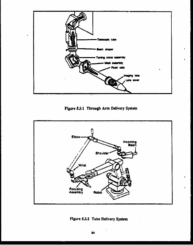
Tluuupia tubs
Figure 5.3.1 Through Arm Delivery System
944

designed into the robot arm, however, and must be provided with an adequate travel
space.
5.3.3 Hybrid. It appears that some type of hybrid system would work best for this
application. In areas where an internal system proved to be optimal, the beam would
be routed through the robot. In areas whereextemal systems were necessary, the
beam would be transferred by a tube delivery scheme.
Beam delivery systems direct light from the output of a laser to a work head that
does final beam shaping. In this section, the important characteristics of the
component hardware needed for beam delivery systems are described. Then, the
optical system design considerations for the laser paint removal application are
discussed.
Components. A beam delivery system requires optical components and mounting
hardware appropriately designed for the particular application. In the case of a
dynamic system, controllable motorized mounts and control systems are required.
Transmissive Optics. For CO2 lasers, the materials used for transmissive optics at
10.6 micrometers Include silicon, germanium, potassium chloride, and zinc selenide.
Of these, zinc selenide is the most useful for high power applications because it has a
relatively low absorption and high thermal conductivity, reducing the possibility of
thermal damage from high power laser beams. It is also somewhat transparent tovisible light, so alignment may be verified using He-Ne laser light. However,
although the absorption is relatively low, the transmission through a typical optical
element is only about 70%. Therefore, if a large number of optical elements are used
in the optical system, the accumulated loss will be high. As a result, reflective optics
are often used.
Reflective Optics. Reflective optical materials iclude silicon, molybdenum, and
copper. Silicon with a high reflectivity silver coating is an economical method to
.5 I ME

achieve a high reflectivity surface. Copper is used more often in high power
applications because of the excellent thermal conductivity. Copper ;s soft. axl the
surface is sensitive to scratching, and are not suitable for use in dirty c•. •ronments.
Molybdenim is the most rugged CO2 laser mirror surface. It has high reflectivity,
about 98%, and is the easiest mirror to maintain in dirty environments.
For high-power applications, over 1 kw, it is advisable to use some sort of efficient
heat sinking, or water cooling. This will improve the reliability of the mirrors, and
reduce the effects of thermal effects that can distort the mirror surface and affect
beam quality.
Additional Considerations. The optical elements and any coating applied must be
able to withstand the high powers, and should be easy to maintain. Also, real-life
optical components introduce aberrations.
The propagation of the light beams through leonses and off of mirror surfaces are
predicted by the paraxial theory, which considers only those rays that propagate near
the axis. Aberrations are deviations of the light rays from the predictions of the
paraxial theory. Aberrations are classified into different types including spherical
aberration, coma, field curvature, distortion, and astigmatism. Spherical aberration is
the result of the off axis rays coming to focus at a slightly diffr', cnt point than near
axis rays. This effect is reduced by using doublets that combine positive and
negative elements. Coma is effectively different magnification from different parts of
the lens. Curvature of field causes images to be sharper on curved, rather than flat
surfaces. Astigmatism is the result of rays propagating through the two perpendicular
planes that contain the object and the optical axis coming to focus at a different
point. Astigmatism causes a elliptical blur around the image. One disadvantage of
using off axis reflective optics for waveguiding applications is the resulting large
astigmatism.
go

Mounting Hardware. Several manufacturers produce optical mounting hardware
that can be controlled with motorized drivers. Often, specialized optical systems are
machined from raw stock. Mounting hardware is typically manufactured from
aluminum, although for special applications steel or superinvar (low-coefficient-of-
expansion steel) are used. The important consideration in the design of mounting
hardware is stability, accuracy, and precision. Moving optical mount design must
address backlash, and additional vibration factors.
The mounted optical component diameters should be sufficient to capture the beam,
but consideration must be given to the space available within the beam delivery tube.
The optical systems will be bulkier with motorized mounting systems and cooling
apparatus.
Optical System Design. The design of an effective beam delivery system must work
with the types of output beams available with current high-power laser technology in
terms of beam cross section, divergence, and uniformity. Beam propagation effects
which impact the design include diffraction, thermal blooming, and the potential
breakdown of air from a tightly focused beam. The design is ultimately determined
by the desired depth of focus at the work head, the overall path length, and the
difference in path length between the extreme positions of the work head in practical
application.
Diffraction. Diffraction effects cause any finite diameter beam to diverge. In
general, the larger the beam diameter, the smalltr the divergence. Optical waveguidesystems are used to control both the beam size and the divergence, but diffraction
effects will limit the ability to maintain a small beam diameter. To illustrate, the
divergence of two ideal Gaussian-profile beams is indicated in the graph of
Figure 5.3.3, which shows the bcam diameter (where intensity is down by 1/e from
the peak) as a function of distance. The 0.5-inch-diameter beam has a significantly
more pronounced divergence, expanding to 3.9 inches in just over 80 meters. The
2.0-inch spot, on the other hand requires a 300-meter path length to have the beam
'7

Beam Diameter vs Distance(Gaussian Beam)
30 .
--.- 0.5" beam diameter
* 2" beam diameter25
S 20-U
J 15
I 10-
5
00 50 100 150 200 250 300
Distance (meters)
Figure 5.3.3 Beam Diameter vs Distance(Gaussian Beam)

diameter reach 3.9 inches. This calculation indicates that a 2.0-inch-diameter beam
can be transmitted over an 80 meter path before it expands up 10% of its original
diameter. In addition, changes in path lengths on the order of 20 meters do not have
a significant affect on the beam diameter.
The ideal Gaussian mode profile assumed for this calculation is only an
approximation for the laser systems proposed to be used for this application.Different beam profiles propagate differently, and these effects must be carefully
considered in the design of the beam delivery system, particularly in the design of asystem which is adaptable to different path lengths.
Thermal Blooming. Thermal blooming is related to a change in the local refractiveindex of the air due to thermal effects. This region then acts effectively like adiverging lens and causes the beam to spread. It also causes distortions in the beam
pattern. Thermal blooming is exaggerated by humid air, which absorbs the laserradiation more effectively and causes localized heating. This effect usually warrants
operating high power laser beams within an controlled environment.
Air Breakdown. Another consideration for high-power laser beam propagation isthe effect of air breakdown because of high electric fields. The electric fields of thelaser radiation can exceed air breakdown (the practical breakdown field is related to
the composition of the air) if a high-power, coherent laser beam is focused to a very
small spot. Therefore, the beam delivery system should not k-equire bringing thebeam to a tight focus.
Path Lengths. For long paths (over 10 meters), a low-divergence beam out of thelaser is desired. Even with a low-divergence beam, waveguide optics will probably
be required to maintain the beam size at the work head. For short paths (under10 meters), waveguide optics will be needed if the beam divergence restriction on thelaser output is reduced.
9.

For Ell paths, at each joint, a set of mirrors on a motorized mounts will be needed to
change the beam direction. The motor controller must be controlled and tied into therobotic system controller. The control system must be able to control mounts on
joints for each degree of freedom. For the beam delivery system, this could be as
few as none, or as many as six depending on the flexibility of the work head system
and the type of robotic system used. If curved mirrors are used, they can double as
wavqguide elements. Astigmatism is more pronounced for off-axis illumination
however.
Depth of Focus. The focal plane of an optical system is determined by the focal
lengths of the elements and their separation. Since the focal length of the optical
elements is constant, the separation between the elements must be used to control the
focal plane position. This also implies that as the path length from the laser to the
target changes, the focal plane of the optical beam delivery system will change.
Therefore, the beam delivery system must demonstrate the ability to compensate for
these effects by changing the separation of the waveguiding elements. For a dynamic
laser beam delivery system, the movement of the optical elements that adjust the
beam waist must be able to respond within the time frame of the motion of the work
head. Because of the time required to move these waveguiding elements, it is
unlikely the beam delivery system could respond in the time frame of a laser pulse
period. This points toward a system that moves a work head to one position, strips a
set large region (approximately 1 square foot), then moves to another position.
Alternatively, a slowly scanning system could overcome this problem.
The dependence on the focal plane position can be reduced by using a long depth of
focus. The depth of focus is directly proportional to the focal length of the optical
system. A long depth of focus produces a more constant diameter beam over longer
distances. This type of beam is easier to accommodate at the work head, and would
be advisable if substantial path length changes are anticipated. One disadvantage of
the long depth of focus is that the beam will maintain a high intensity over long
100
distances, which increases the hazard of the beam causing damage if it is accidentally
directed away from its intended target.
Stability. Stability is an important factor for the beam delivery system. The longer
the path length, the more sensitive the laser beam position at the end of the path is to
small changes in the mirror position at the start of the path. A O.1-mrad angular
deviation causes a 1-mrm shift in the beam center at a distance of 10 meters, and a
1-cm shift at a distance of 100 meters. Therefore, stability of the optical mounting
hardware to a reasonable tolerance must be demonstrated. As discussed earlier, the
mounting hardware and design have a significant affect on system stability.
Enclosed vs. Open Systems. One question that arises in the design of a beam
delivery system for the paint removal application is whether to use an open or a
closed beam path. This decision impacts the development of the robotic system.
From a functional standpoint, it impacts the safety, mc?.intaiability, and performance
of the beam delivery system. From a safety standpoint, an enclosed system is
desirable because the laser beam from this Class IV laser is available to the human
eye, and there is the possibility that the beam could be interrupted by either personnel
or equipment, causing significant damage in either case. To satisfy OSHA
regulations, personnel must be isolated from the laser beam. Therefore, if personnel
are allwed in the room during operation, an enclosed system is required.
Enclosed systems would allow an over-pressure to be maintained over the optical
elements. This, coupled with the additional protection from debris provided by the
enclosure, would lead to improved reliability and reduced maintenance for the optical
elements. There would also be a reduction in the potential for thermal blooming
effects, and a resulting improvement in performance. Note that accessibility of the
optical components and mounting hardware will be required.
101
Over very long path lengths, unsupported enclosure systems are subject to droop,
wbich would hinder beam propagation and must be accounted for in sw -,m design.
This factor could ultimately lead to a path length limitation.
Development and Risk. Beam delivery systems for high-power CO2 laser systems
are common for industrial and material processing applications such as cutting,
welding, and hardening of metals. These systems routinely cover path lengths of
10 meters, and often are adaptable to path length changes. Although these systems
are relatively straightforward, the system must be carefully designed to maintain
beam quality, and to produce the appropriate beam diameter at the material surface.
The extension of this technology to very long path lengths (over 100 meters) will
not be straightforward. Stability, and adaptability of the system are crucial.
Additionally, if a control system must be developed to maintain the focus -n the
appropriate place as the path length changes, the risk would be even higher.
However, the risk here is related to the ability to determine an appropriate design
rather than to develop new technologies. The development risk here is categorized as
moderate.
102

5.4 Work Head
The work head is used to shape the beam just before hitting the target. In most
situations, the work head will also contain a sensor element that controls not only thework head optics, but the beam delivery system and the laser. In this section, beam
integration methods are discussed. Then the performance requirements for paintremoval are outlined. Some of the proposed work head concepts are described, andfinally the development areas and risk are discussed.
Beam Integration. In systems utilizing lasers with outputs that are not uniformacross the beam profile, optical systems may be utilized to improve the beam profile
at the aircraft surface. Beam integration may be accomplished in several differentways including a static, spatial beam integrator, or scanning system. The basic
concepts are discussed below.
Static Systems. Standard static spatial beam integrators use a multifaceted sphericalmirror. Each facet, which is typically a planar surface, reflects a section of the beam,and these sections are directed to overlap at the focus of the sphere. The beam size
is determined by the size of the facets. The number of facets, and therefore the beam
size in the focal plane, is set by the desired level of integration. Typical industrialheating applications utilize between 16 and 36 facets. The focus is typically a few
inches.
The depth of focus issue is important for the beam integration system. If beam
integration is done within the work head, the ultimate depth of focus of the system is
dependent upon the optics in the work head. In the case of planar facets, thedivergence of the small beam section will be dictate either by the diffraction of the
small beam size, or the divergence of the original beam, whichever is greater. Thedepth of focus of the spherical focussing element determines the distance over which
the small beams remain overlapped. To obtain a large depth of focus, the integratinghead must be large enough to accommodate long path lengths.
103

Scanning Systems. Scanning systems use time integration, sometimes in
combination with spatial averaging to achieve a uniform distribution of light on a
surface. These types of systems rely on scanning mirrors that direct the beam to
different locations within a region on a dme-scale short with respect to the total
dwell time at that location. As a specific example, consider a rastering system that
rapidly scans a 1-inch beam across a 5-inch strip. On average, each position within
the strip sees every x-position of the beam, resulting in averaging over this one
dimension. The other dimension is averaged in the same way. Note that edge effects
must be dealt with separately. Timing, and raster-beam spot size must be carefully
designed to achieve the appropriate level of averaging for a given application.
There are some other important issues to consider in the choice of a beam integration
system. The integrated beam is no longer phase-coherent across the beam.
Therefore, its propagation and focussing properties are not that of the Gaussian, or
near-Gaussian beams that are incident on the Integrator. In general, a spatially
averaged beam will not focus to a small spot. There are also diffraction lines
associated with the finite edges of the small facets.
Use in Other Applications. Beam integration systems ac. commonly used in
industrial laser applications where beam profile is important. Heat treating is one
major application area. UTIL incorporates Spar integrators, manufactured by Spar,
Inc., in their applications which require uniform beams. UTIL also uses a beam
spinner system that rotates the beam around its propagation axis just prior to the
target. The rotation averages the beam profile around the axis, improving uniformity.
Circularly symmetric patterns would not be averaged out with this method.
Alternatives. There are other methods to achieve a high quality beams that are parts
of the laser system, rather than the work head. This includes beam paths which
integrate over the gain medium, and master-slave oscillator type systems. UTIL has
done significant development in this area for laser applications in laser radar systems.
The applicability of the master-slave oscillator system to 15-kw systems has been
104
demonstrated; however, significant alignment is required, and practical long-term
operation may not be possible.
Performance Requirements. For paint removal applications, the beam profile must
be uniform and repeatable to assure that the paint is completely removed, and the
aircraft surface is not damaged. A practical work head system design will
accommodate the available laser output parameters and produce a uniform exposure
at the target. The tolerance to nonuniformity is dependent on the surface tolerance to
laser fluence. Avco determined experimentally that the beami profile must be uniform
to +/-10%.
Beam Shape, The beam size and intensity fall off will have an impact on the paint
removal at the interface between two adjacent laser footprints on the surface.
Effective exposure at the interfaces also requires careful coordination of the robotics
or scanning mirror arrangement. For a Gaussian beam, the intensity profile is
specified by the full width at half maximum (FWH-M). For small FWHM, the
alignment between two adjacent foot prints becomes more critical. Figure 5.4.1I
shows the overlap of two adjacent Gaussian laser footprints with FWHMV's of 1.7 cm
and 5.0 cm. The solid line shows the sum of these two patterns which is the total
energy density imparted to each spot after two laser pulses. In each case, the beam
separation is set so the beams cross at the intensity-half-maximum. Figure 5.4.2
shows these two beams after a misalignment of 0.5 cm. It is apparent in the case of
the 1 .7-cm-FWHM beam that the integrated intensity at the interface has dropped
below the 10% reduction limit, and therefore paint stripping will not be uniform.
The 5.0-cm-FWHM beam is not sensitive to the 0.5-cm misalignment. These results
are summarized in Figure 5.4.3, which shows the relative energy density at the
interface (summed intensity) as a function of the misalignment of the beams. In this
graph, a positive Dclta-X indicates increased separation, negative Delta-X indicates
decreased separation. The +/-10% deviation limitation is shown on the graph. Note
that for the 1 .7-cm-FWHM beam the deviations of less than 0.75 cm result in an
10S

I.,
0.9
>1 0.8
S0.7V
0,6
S0.5di I'
Z 0,4 1M/di 1%cc 0.3
0.2 *
0 ,
-7,2 ý5,6 -4.0 -3.2 -1.6 0 1.6 3.2 4.0 5.6 7.2
'I,.
0.9
a 0.8
di 0.7V Is
0.6
0,3C A
-7.2 -5.6 -4,0 -3,2 - 1.6 0 1,6 3,2 4.0 5.6 7,2Distance (cm)
Figure 5.4.1 Laser Footprints
Top: F"WHM = 1.7 cm
Bottom: FWVHr, = S.0 cm
100
J i i ; : l - - -' ' -' .. . .

0.9
V 0.8
0.,6
4' 0. U04)
, I, 4'.;I I , , . . . . . . .
0.
-7,2 -5,6 -4.0 -3.2 -1.6 0 1.6 :3,2 4,0 5.8 7.20.9 .
0.- - ,W• 0,7
0.4
0.3
0,2 ,
0,1 1 •, ..
-72 -5,6 -4.0 -3.2 -1.6 0 1,6 3.2 4.0 5,6 7,2
D~istance (cm)
Figure 5.4.2 Laser Footprints0.$ cm misalignment
Top: FWHM a 1.7 cmBottom: FWHM = 5.0 cm
107

Interface Energy DensityAdjacent Laser Footprints
2.0--- 1.7 cm FWHM
1.8 U- 5.0 cm FWHM
1.6
1.4
U 1.2
3 0.8 t
fc 0.6 10% Deviation
0.4
0.2
0.0 , ' - ' ' '-1.5 ,1.0 -0o.0 0.5 10 ,5
Delta-X (cm)
Figure 5.4.3 Interface Energy Density Adjacent
Laser Footprints
108

overshoot of the energy density at the interface that exceeds the limit, and could lead
to surface damage.
This analysis assumes a smooth Gaussian beam. The beam delivery system and
focussing head optics dictate the exact intensity pattern. In reality, most beams will
have diffraction side-lobes. The impact of this modulation on the paint removal is
dependent on the intensity and spacing of these side-lobes. If the side-lobe spacing is
small compared to the thermal diffusion length of the target, the modulation will be
washed out and will not have an impact on the paint removal. If the fringe spacing
is larger, however, the modulation will be evident in the thickness of the paint
removed and/or the amount of damage to the aircraft skin.
Temporal Stability. The requirement for temporal stability of the laser power output
and beam profile is determined by the integration technique that is used. Temporal
variations in the laser power that are short with respect to the integration time will be
averaged out. Longer-term variations must be accommodated by a feedback system
that controls the exposure time of a certain area. In most cases, the temporal stability
of the laser system will be a given, and the integration scheme must be engineered
around this parameter.
Available Technologies
Rastering Concept. One technique which has been considered for paint removal
applications is to raster a nominally i-inch-square beam over a large area (I square
foot). The entire area is covered once every second. Beam integration is obtained by
slightly displacing the center of the beam on each sweep. Sixteen sweeps are made
to clean a nominally 2.5-mil-thick layer of paint. With the use of a spectroscopic
sensor system, some of the 1-inch square regions will not be illuminated on a
particular sweep if the sensor indicates the paint has been removed.
This particular system alleviates some of the requirements on the laser stability by
using the sensor to judge and to control the exposure time. In this case, if the laser
109

power suddenly increased on 1 sweep, this "overexposure" would be offset by not
illuminating the section on the next sweep.
For the integration method to be practical, the beam uniformity at the aircraft surface
must be quite good because only 16 pulses or fewer are used to average. In the casewhere the paint is thin in some area and only one or two pulses are used.nonuniformities may not be sufficiently averaged. The averaging system would be
most effective if the sensor were also used to determine the averaging pattern. For
this to be effective, however, the sensor spatial resolution must be much smaller than
the beam size. The lower limit on the necessary resolution would be set by the
thermal diffusion length of the target. Of course, higher resolution will necessarily
require more processing and subsequent closed-loop control.
As mentioned above, the edges of the large area will not be sharp with this averaging
method, This effect must be dealt with either by using a high-resolution sensor, or
by keeping the integration protocol in memory, and recalling the protocol used in
adjacent regions. Again, this adds to the computational complexity of the system.
Reliability, Maintainability, Safety, This work head system concept requires as a
baseline motorized kinetic mounts, reflective optics, the sensor system, and associated
control electronics. The work head optical system be capable of rigid and repeatable
motion, which can be realized by current technology. While kinetic systems are not
as reliable as fixed mounting systems, they are generally reliable if used within their
specified operating load conditions.
The reliability of the optical components hinges on the adequacy of the reclamation
system. The optical elements will be subject to fouling from debris given off by the
paint removal process. The lifetime, as well as the maintenance of these elements
depends on the reflective materials used. Molybdenum coated mirrors are
recommended if fouling is likely because of their durability. Ready access to the
work head optics would be essential for ease of maintenance.
110

It is important that the work head be able to tolerate the back reflection of the laser
beam should it strike a highly reflective surface such as aluminum. Water cooling
may be required to reduce heat build-up.
The sensor element would also need to be shielded from high-intensity reflections by
some filtering or appropriate shielding. The reliability of the sensor system is as yet
unspecified, but should be analyzed because it could be the reliability driver of the
work head system.
The electronics should be realizable with standard off-the-shelf components, and do
not pose a significant reliability or maintenance issue, though they should be
accessible for repair.
Stationary. Another approach which has been suggested by Avco is a stationary
beam integration system. Avco's modified beam integrator is similar to a Spar
Integrator, but uses convex mirror facets rather than the standard planar facets. These
facets serve to expand the different portions of the beam, and reduce the path length
needed within the work head to result in a lO-X-10-cm beam at the target.
This system has a short depth of focus. Depth of focus must be sufficient to
accommodate the largest curvature of the aircraft that is stripped. Robotics accuracy
must be high enough to accommodate the sensitivity of the focal plane. For a
0.5 inch depth of focus, +/-0.25 inch robotic accuracy is required perpendicular to the
aircraft surface.
Reliability, maintainability and sarety. This type of system would be very reliable
particularly because there are no movinj parts. The issues of reliability and
maintainability of the optics are the same as in the previous system.
The short depth of focus is desirable from a safety standpoint, because the beam
diverges rapidly.
111

Although a paint identifier sensor would still be advisable to accommodate variations
in paint thickness over large scales, the resoiuion of the sensor could be fairly low,
and the feedback control less complex. This reduction in complexity would provide
the associated improvement in reliability and maintainability.
Additional Considerations. The weight of the work head system will impact the
stability of the robotic system. The work head weight should easily be less than 100
pounds. The work head center of gravity may also be a consideration for the robotic
system. Counter-balancing weights may be required.
Development/Risk. Several key areas exist for development of a practical work
head system. It is possible in the design to trade off the complexity of the sensor
and control system with the complexity of the optical system, as was alluded to in
the above discussion. The key to an operational scanning-type system is a functional,
high-level sensor system. This type of a system may be essential for paint removal
from composites. Successful development of this system hinges on the sensor
system. The development of a paint identifying sensor is still in the early stages, and
applicability to a large scale, field usable system must still be proven. While
technologically realizable, the demands on the signal processing and control system,
as well as the laser requirements of such a system may not be easy to integrate into a
workable system.
On the other end of the spectrum is a system utilizing a less sophisticated sensorsystem in conjunction with a laser and optical system that produces spatially and
temporally uniform illumination at well defined, open- or closed-loop controlled,
positions. This approach results in a simpler and easier to maintain system, but may
not be adequate for stripping composite skins, particularly if the paint thickness is not
uniform.
112

5.5 Sensor Systems
The sensor technology that accompanies the robotic system, including standoff and
collision avoidance, are available off-the-shelf, and do not pose a significant
development issue. A sensor system that adequately controls the laser and work head
optical system, on the other hand, represents a significant development challenge.
Even more difficult is the combination of the sensor technology with the robotics
technology. It is difficult to combine the sensor with the robotics control system
when the sensor window leads the paint removal window because the robotic control
system must be able to ascertain the exact relationship between the sensor window
and the laser beam window. This requires either a priori knowledge of the aircraft
surface, or complicated sensor system and control circuitry. The integration of a
sensor into the robotics window will require that the sensor be able to process the
necessary data within the time allowed for the control signal to be sent. This could
prove a difficult task if the sensor has to conmpare spectroscopic signatures with a
known data base.
Several types of sensors are available, and have been proposed for use in the paint
removal application. These include imaging systems, optical spectroscopy, acoustic
sensors, and magnetic sensors. Imaging systems would be appropriate to determine
the shape of the laser footprint. Depending on the resolution, imaging systems can
requ're considerable electronic processing to produce a useful output. Imaging
systems also require predictable illumination, because illumination changes cause
significant changes in the video image. They would not be readily adaptable to thedifferent surface curvatures for this reason. The CCD elements, though transparent to
radiation at 10.6 pim, would still need to be protected from reflections and radiation
that occurs from ignition of the paint and contaminants on the surface. Sensitivity to
this stray light can be reduced by using monochromatic illumination and filtering
systems. CCD cameras also have a characteristic persistence, which may cause a
problem for very fast imaging requirements.
113

Optical spectroscopy has the advantage over imaging that the resolution may be
lower. However, the amount of processing required for each pixel of spectroscopic
information is significantly greater. Depending on the size of the library of paint
absorption spectra, the matching procedure could prove cumbersome. USBI has
determined that the spectroscopic system must identify the surface within 0.67
milliseconds and that a color sensor has not been found that can work on this time
scale. It is possible that clever processing, and the use of some a priori information
could reduce the processing burden. However, most spectroscopic gas identification
systems have processing times on the order of several seconds. These systems only
have a few isolated lines to identify. Furthermore, the data presented by InTA do not
show readily identifiable spectral lines within the visihle wavelengths interrogated.
Spectroscopy instrumentation requires some calibration or referencing scheme to
produce reliable results. The spectroscopic system could also be thrown off by the
flash and the smoke and debris that accompanies the paint removal as well as any
contaminants, dirt, or oil that may be present on the aircraft surface.
Ultrasonic measurements could be adversely affected by the acoustic signal that is
generated by the laser paint removal process.
Electromagnetic sensor sensitivity would depend on the composition of the paint.
Different paints have different dielectric properties. Some are good insulators, and
others are conducting.
Contour following and collision avoidance, color discrimination and global
positioning sensors were evaluated against the system requirements. Laser, ultrasonic
and electro-optical methods are seen as the best methods. Magnetic methods are not
effective on all types of substrates, as is the case with capacitive methods.
Performance requirements dictate that an extensive sensor system be used. The
following capabilities are required of the sensor system. Each of the sensor
subsystems are discussed in greater detail following their definition.
114

Collision avoidance/obstruction detection. Collision avoidance capability is
essential to protect the aircraft and other objects within the work envelope.
Surface contour following/stantc , control. In order for the laser energy to be
efficiently directed toward the aircraft surface, the beam must be normal to it, Thework head must operate at a relatively constant distance from the surface in order tokeep the focused portion of the laser beam in contact with the area to be stripped.
Color/substrate discrimination. The decision to pulse (strip) a surface is dependent
upon the spectral response (color) of the material. Knowledge of the underlyingsubstrate material allows for a more robust stripping algorithm.
Global positioning. An ALPS system requires the ability to orient itself with respect
to the aircraft. The aircraft cannot be located in exactly the same location each time
the stripping process begins.
Surface mapping. Some type of mapping capability is needed to allow the system
to generate "tool" (work head) paths over the aircraft surface.
5.5.1 Collision Avoidance/Obstruction Detection. Collision avoidance isaccomplished by ensuring that the robot arm does not come into contact with the
aircraft during processing. Obvious deviations from the working CAD model of the
aircraft will be detected during global location and accounted foi during path
planning.
Several methods could be used during processing: ultrasonic, laser, electro-optical, orvision (cameras). Any of these will provide the desired information. Since there willbe a number of sensors and sensor processors incorporated into the conceptualdesign, it would prove beneficial to utilize anothur one of the sensor systems and its
controller. Based on the fact that a vision system will be utilized for color
discrimination and global locating, it appears that the best approach would be to use
111

a camera to look ahead of the laser work head to the next robot arm position for
obstacles which might be encountered during the next move. The vision systemwould use the same processor as the color-discrimination and global-locating
functions, all tasks which are required, but are performed at different intervals.
First-level collision avoidance is expected to be handled by' the controller and its
software. It should be quite feasible to program the controller to prevent the robot
from occupying the same space as the aircraft at any point in time. The ability to do
this is predicated on the controller's knowledge of the space occupied by the aircraft,
the space occupied by the robot at any instant in time and the ability to distinguish
these two spaces.
The criticality of collision avoidance warrants a sensor-based redundant system to
back up the controller. This system can br either a contact-type where a probe
physically touches the aircraft (or other collision hazard in the work envelope) or a
noncontact-type such as a sonar transducer that detects the presence of objects by the
reflections of sound emitted by the transducer.
The Cimcorp robot used in the Air Force NDI system uses instrumented "bumper
pads" around the robot arms. If the robot comes in contact with an object, the pad
deflects to prevent damage to either the robot or the object (likely to be the aircraft)
and shuts the system down to prevent subsequent damage. See the Appendix for
more information concerning Cimcorp and the NDI system.
S.5.2 Surface Contour Following/Standoff Control. The specific requirements
for surface contour following and standoff control will be different for each ALPS
system concept. Any concept, however, can be expected to require some knowledge
of the local surface normal and the distance to the surface. The InTA design only
requires that the laser beam be within 60 degrees of the surface normal and within 5
cm of its average standoff distance. The Avco concept, on the other hand, requires
that the beam be within 5 degrees of the surface normal. It must be remembered,
116
- -L M,:- m,
however, that neither of these values have been verified and arm subject to further
refinement. In either case, the work head must be able to calculate the local surface
normal and the distance to the surface. There are a variety of techniques to calculate
this information.
Standoff Sensor Systems. Standoff sensor systems include contact and noncontactmethods. Systems which consist of multiple sensors provide information aboutnormal orientation to the surface, as well as standoff distance, for a three-dimensional
perspective.
Contact Methods. Contact methods usually consist of touch probes. A probe, of
specified standoff length, would remain in contact with the aircraft surface during
processing. For two reasons contact methods are not deemed appropriate for in-
process use and are not considered further. The first reason is the requirement not to
damage the aircraft surface. The second is that the changing shapes of the aircraft
surface and the fixed positioning of the contact probes could lead to inaccurate
standoff control.
Noncontact Methods, Noncontact applications include magnetic, capacitive, laser,
ultrasonic, and electro-optical.
Magnetic. Several types of magnetic sensors are used as proximity devices.
Reed relays are one example. A fixed conductor and a reed tube, made of amagnetic material, arm sealed in a glass tube. The magnetic reed is moved by the
approach of a small permanent magnet which closes the electrical circuit.
Another magnetic sensor is the "Hall effect device" which utilizes the generation
of a potential in a semiconductor plate. This plate carries a current in thepresence of a magnetic field perpendicular to the plate. The potential difference
generated between the two sides of the plate is orthogonal to the direction ofboth the current and the magnetic field. This is called the Hall voltage.
117

Capacitive and Inductive. Capacitive transducers have two parallel conducting
plates. When the plates are displaced relative to each other, the capacitance
changes so that the impedance to the passage of an alternative current (AC)
varies.
Capacitive displacement/proximity sensors generally work only for small standoff
ranges. These sensors respond to the presence of metal. Although the sensors
are actuated by any type of metal, their sensitivity to nonferrous metals is
sometimes only one third that of ferrous metals.
One noncontact capacitance clearance control system is designed specifically for
laser operations. This system maintains an optimum focal point by measuring the
clearance between the laser cutting nozzle and work piece. The system is
incorporated into the laser work head with a copper nozzle used to act as an
electrode. The nozzle electrode and the work piece provide a variable
capacitance. Changes of clearance are detected by a high-frequency oscillator
circuit. The shift of frequency is converted into an analog direct current (DC)
signal.
Proximity sensing fr&-n nonferrous metals can better be accomplished with AC
inductive sensors. The ability to differentiate between ferrous and nonferrous
metals could be useful in this application.
Laser Gauges. The laser contour sensor used the basic geometric law of
triangulation. The contour sensor contains a solid-state laser diode and camera
mounted in a sealed, rugged protective housing. The solid-state photosensitive
imaging array, high-resolution optical, and laser diode are generally factory
prefocused and rigidly positioned in a monolithic mount precision-machined from
a single block of material. Standard standoff ranges are available from 1 inch to
120 inches. Other fields of view and standoff distances can sometimes be
custom-delivered. These sensors provide a remarkable ability to measure soft,
11i

wet or delicate surfaces because they do not destroy or alter the materials they
measure. In addition, their small laser spot makes them ideal for measuring
highly contoured parts. Laser contour sensor advantages are higher speed, more
repeatable measurement data, and lower maintenance costs that are due to the
noncontact approach.
Sensor data is usually processed real time (but can be stored in ASCII files and
can be analyzed by most data analysis software or programming language). Most
systems include a sensor head, connecting cables, a multiplexer driver box and aninterface card. When measuring surfaces with little variation, the sensor can
operate in fixed exposure modes, where exposure times are set, thus increasing
measurement speed. For surfaces that vary in texture, color or reflectivity, the
sensors can be set to automatic exposure in which exposure time Is adjusted with
each measurement to maximize accuracy.
Ultrasonics. Ultrasonic sensors use ultrasonic wave-reflection techniques to
measure accurately distances through air or other gases. Ultrasound is generated
at high frequency from the tip of a transducer, which senses echoes from a
reflective surface. Time of flight is determined by the system, which converts
the data to distance or thickness and displays It and/or sends it to the computer.
Applications include thickness and distance measurements or other dimensional
checking, edge location and robotic arm positioning. Accuracies of 0. 1% of the
measuring distance can be achieved. Measuring ranges generally vary from Iinch to 60 inches.
A leading system incorporates state-of-the-art ultrasonic technology to provide
measurement and control data. The system transmits narrow beam acousticpulses at a user selectable rate, processes an echo reflected from a target within a
defined range, and provides multiple control outputs, depending on the position
of the target.
11l
- = I !

Almost all target shapes can be sensed, but generally, smooth flat targets, normal
to the beam axis, are easier to sense than rounded targets. The displacement of a
flat target can be detected at a greater distance than a round target. If a smooth
flat target is inclined more than approximately 3% to 8% to the normal of the
beam axis, part of the signal is deflected away from the sensor and the sensing
distance is decreased. Ultrasonic sensors can be affected by humidity and air
turbulence. Ultrasonic waves can also be sent through a stream of water.
However, for this application, this is unacceptable.
Electro-optlcal. Electro-optical sensors detect surfaces by the use of a light
source such as a light-emitting diode and a photosensitive cell. A lens is used to
image the light source at a point in space where the light will be reflected from
an object back through another lens to a photosensor.
This type of sensor is characterized by a modulated, infrared, noncontact device
used to determine part presence, absence, or object position. Three distance
zones are usually identified (NEAR, OK, or FAR). The OK zone can vary from
0.003 inches to 20 inches, depending on standoff. One system uses infrared
triangular reflection with a single optical lens to detect whether an object is
within an OK region. Dual-modulated IR emitters inside the sensor project a
small spot on the object. The single lens and small spot size permit highly
directional sensing. Reflected energy from the surface to a single detector then
determines the object's range status. A built-in switching hysteresis is sometimes
provided, and a response time of 10-20 milliseconds can be expected.
Similar systems use infrared (IR) light and a dual nirror configuration to
measure distance over a wide range of reflective su,,,tces from diffuse to
specular, including mirror or glossy paint surfaces. Analog output data are also
available. The sensor is housed in an anodized aluminum case and employs
integral air purge to minimize contamination of the glass optical surfaces in
hostile environments.
120

5.5.3 Color/Substrate Discrimination
The decision to strip an area of paint is a function of the type of paint (primer or
topcoat) and the substrate (aluminum, composite, etc.). At the present time, this
decision is made based on color. While the human eye can easily distinguish color
differences among the primers and topcoats used by the Air Force, this task is very
difficult for an electro-optical vision system handle,
International Technical Associates (InTA) of Santa Clara, California, is In the process
of developing a color discrimination system using an array developed by Lawrence
Livermore National Laboratories. The theory of this system is quite simple, although
its design is not. A painted surface is exposed to a light source containing a broad
range of wavelengths, from IR to UV. This is slightly beyond the human visible
range. The exposed surface reflects the light in intensities that vary with wavelength.
Each paint apparently has a unique spectral response. The InTA system compares
this response with a "library" of stored colors. Library colors have been previously
stored in a similar manner.
Issues regarding camera performance:0 Can the array algorithm resolve colors with similar spectral responses (i.e,,
shades of grey)?• Will the spectral response of a dirty, weathered paint be close enough to its
corresponding library color for an identification?0 Will the system be fast enough to allow paint-type determination to keep pace
with the laser?
Substrate discrimination is of importance from the standpoint of aircraft safety. Thelaser energy has the ability to damage the substrates. Aluminum can withstand
(reflect) more energy than composite. In light of this fact, the ALPS system can strip
aluminum surfaces to bare metal, while a layer of primer must be left on thecomposite to protect the epoxy resin. The whole issue of laser interaction (damage)
I121

with the various substrates is not, to date, well understood. Composites have a much
lower threshold for laser energy damage than does aluminum.
If one limits substrate differentiation to metals and nonmetals, the property of
conductivity (of metals) may be used to distinguish metallic substrates from
composite. Eddy current sensors may be used for this applications.
Surface/Paint Discriminators. Color and material discriminating functions also
employ contact and noncontact methods.
Contact. Contact methods of material sensing include the eddy current process.
Typical eddy-current sensors work best with metal surfaces. Composite surfaces will
not allow sufficient surface currents to be induced, and thus, will not alter the
measured electromagnetic fields enough to get reliable measurements. Contact color
instruments offer high accuracy and low sensitivity to varying ambient conditions but
were not pursued since these methods are not compatible with either the processes or
the speed requirements.
Noncontact. Noncontact methods are mostly electro-optical. One electro-optical
system permits detection of up to 12 memorized colors and detects subtle color
differences. It is capable of using an RS-232C communication port to send
recognition results to an external computer.
For the light-receiving element, which is the heart of the sensor head, a special photo
diode is utilized. It consists of three chips which incorporate a filter for one of the
three respective primary colors and features high-color sensitivity and wavelength
characteristics. Light reflected by the detected object is resolved into the three
primary colors by this color resolution light-receiving element. After analog/digital
conversion, they are analyzed at the microprocessor and are transmitted as color
information to the control unit.
122
The controller allows a reference color to be stored into memory in advance. The
microprocessor recognizes the color consistent with that stored in the memory from
among the color information transmitted from the sensor unit. Subtle color differencerecognition becomes possible by the process described above based on utilization of
the high-capability color resolution photo diode and independently developed
algorithms. Color recognition in 50 milliseconds is possible.
The Avco study of the InTA system shows that the visible reflectance spectra have a
sufficiently unique signature for all encountered colon. They propose to measure
surface reflectance between laser pulses, analyze the observed effect and then use the
output to control the timing or special movement of the next pulse through the
control system. InTA's product literature is included in the Appendix.
The process involves premapping of the aircraft surface prior to stripping by means
of a 32 x 32 optPal sensor array. The recorded data are stored In memory with paint
and substrate source data that show how the reflectance varies through a range of
energy pulses. A comparison of the source data and actual reflectance during
stripping will tell the control system when the substrate or primer has been reached.
Note that the dominant principle behind this control scheme is color differentiation
and is based on work performed at Lawrence Livermore Laboratories.
The color sensor must determine when the desired base material-stopping color has
been exposed so that the laser pulses can be discontinued. There are several criticalissues surrounding this sensor, including feedback rate and the number of colors thatcan be accommodated.
The color discrimination sensor can either be taught all the colors that it may
encounter or only the colors that require the laser to stop pulsing (base materials).
An estimate of the number of colors to be encountered is shown in Table 5.5.3.
123
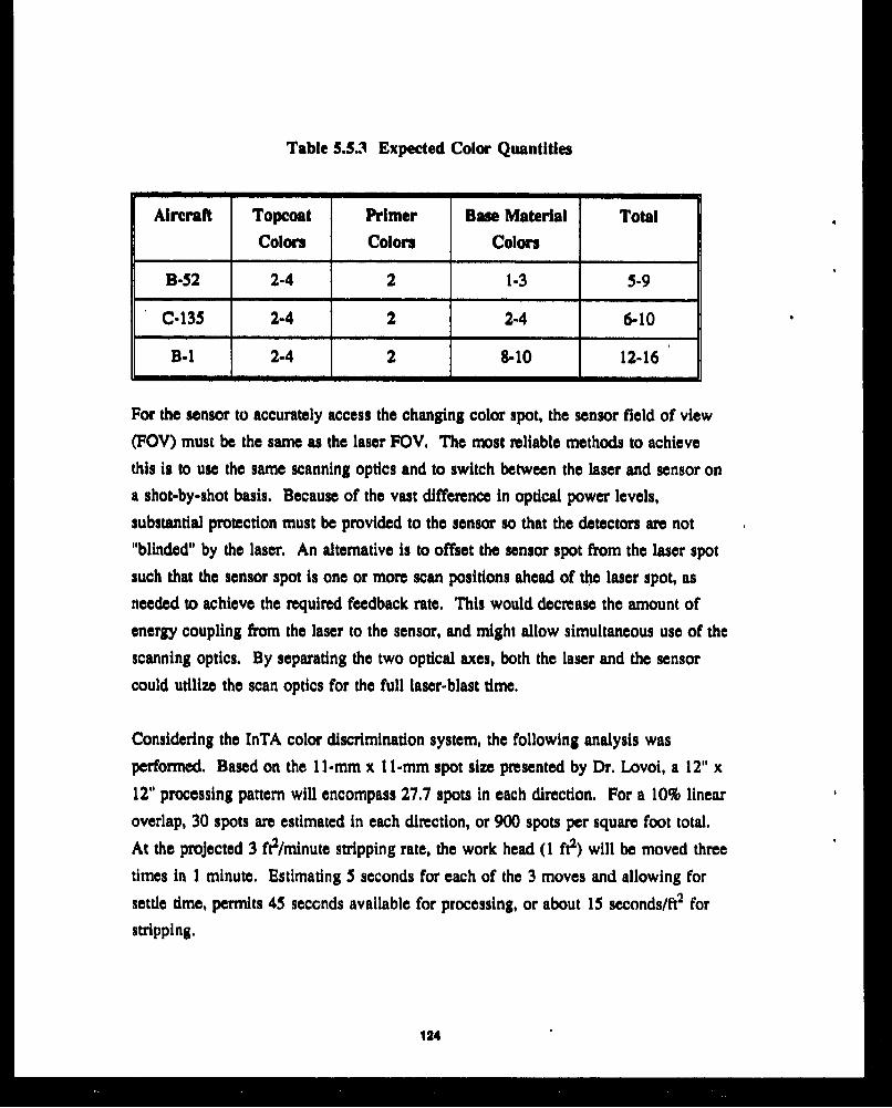
Table 5.5.3 Expected Color Quantities
Aircraft Topcoat Primer Base Material Total
Colors Colors Colors
B-52 2-4 2 1-3 5-9
C-135 2-4 2 2-4 6-10
B-1 2-4 2 8-10 12-16
For the sensor to accurately access the changing color spot, the sensor field of view
(FOV) must be the same as the laser FOV. The most reliable methods to achieve
this is to use the same scanning optics and to switch between the laser and sensor on
a shot-by-shot basis. Because of the vast difference in optical power levels,
substantial protection must be provided to the sensor so that the detectors are not
"blinded" by the laser. An alternative is to offset the sensor spot from the laser spot
such that the sensor spot is one or more scan positions ahead of the laser spot, as
needed to achieve the required feedback rate. This would decrease the amount of
energy coupling from the laser to the sensor, and might allow simultaneous use of the
scanning optics. By separating the two optical axes, both the laser and the sensor
could utilize the scan optics for the full laser-blast time.
Considering the InTA color discrimination system, the following analysis was
performed. Based on the 11-mm x lI-mm spot size presented by Dr. Lovol, a 12" x
12" processing pattern will encompass 27.7 spots in each direction. For a 10% linear
overlap, 30 spots are estimated in each direction, or 900 spots per square foot total.
At the projected 3 ft2/minute stripping rate, the work head (1 ft2) will be moved three
times in 1 minute. Estimating 5 seconds for each of the 3 moves and allowing for
settle time, permits 45 seconds available for processing, or about 15 seconds/ft2 for
stripping.
124

Since there are 900 shot positions/fe and up to 10 shots per position, the derived rate
is now 9000 shots/15 seconds, or 600 shots/second, or 1.667 millixeconda/shot.
Using a worst-case estimate of 0.4 inches/millisecond to clear debris from the sensors"l"view" (using the vacuum system),then the necessary tangential air flow is 23 mph
(0.4 inches/millisecond). Under these assumptions, the color sensor must measureand classify into one of the 11-17 known base material colors in less than 0.67milliseconds. That amount of time does not allow for settling time of the opticsbecause of the scan motion. At this time a color sensor has not been identified thatis fast enough to meet the InTA system requirements of 1.667 milliseconds, muchless the reduced amount of time allotted.
Another issue with color discrimination sensors is the need for a uniform light source
that is much brighter than the ambient. The light could be diffused or pulsed. Adiffused light source to provide even lighting over the viewing surface would be
more than 2 feet square (4 square feet). This light would prohibit movement aroundseveral areas of the aircraft. As an alternative, an array of pulse lights or strobelights could provide for approximately uniform off-axis illumination for each
individual spot position. In general, these could be made smaller, but would be less
reliable.
5.5.4 Global Positioning. A CAD model of the aircraft will be used as a
guideline to generate rough robot-path trajectories before processing. The globallocating procedure will be used to orient the aircraft with respect to the robot'sposition and determine how much of the robot's work envelope can be utilized.Many machine camera-type vision systems exist today which perform similar
functions.
125
5.6 Air Reclamation
The purpose of the air reclamation system is two-fold: remove the contaminated gas
stream (from around the work head) and remove the byproducts of paint stripping
from the gas stream. Removing the contaminated air and replacing it with clean air
is necessary to prevent ignition of the byproducts generated by the laser, to prevent
contamination of the surface, to prevent the escape of toxic materials into the
atmosphere, and to provide a clear atmosphere for the sensor systemp to look through.
Another function of the air reclamation system is to remove these potentially toxic
paint byproducts from the gas stream and to collect them for environmentally
responsible disposal.
Laser paint stripping research has shown the gas stream to be composed of two
classes of material: aerosols and gases. The air reclamation system must remove
both of these types of contaminates. Aerosols are (in terms of the gas stream
produced by laser paint stripping) particulate matter in the form of carbon (soot),
metallic oxides, metallic fumes, and paint particles. Specific characteristics are a
function of paint composition and process conditions. Aerosols may be removed by
a variety of mechanical methods. Common methods include filtration via a fabric
filter in a bag house system. Another system, employing a scrubber, removes
particles by entraining them in water and filtering the water. The trapped particles
are collected and removed as wet filter cakes. Other techniques possible for this
application are electrostatic precipitation or cyclone centrifugation.
The gaseous byproducts are found In the form of hydrocarbons (organics) and oxides
(inorganics). These gases may be responsible for odors, irritants, and toxicity. Thereare two fundamental approaches for their removal: adsorption and incineration.
Adsorption is a chemical process in which the gases are adsorbed (chemically
bonded) to the surface of a solid such as activated carbon. The solid is then replaced
or regenerated by heating.
126
Incineration is the high-temperature burning (oxidizing) in the presence of an excess
amount of oxygen. The byproducts are simple molecules such as H20, CO2, and
NO., which are released into the atmosphere. The system relies on some fuel, often
natural gas, to produce a temperature of approximately 1300°F. As the gSas are
oxidized, they contribute to the burning and serve to reduce fuel consumption.
In some cases, such as situations where a large volume of air contains a relativelylow concentration of volatiles, a combination of both adsorption and incineration is
used. This allows the carbon bed to adsorb the gases from a large quantity of air.Subsequent heating of the bed drives off the gases in a higher concentration than in
the original air volume, This higher concentration of volatiles is more efficiently
incinerated (in terms of the Btu's expended). This type of system is not necessary
for an ALPS application because of the relatively low volume of air required, 2000
SCFM.
Complete air reclamation will require a system with the ability to remove particulate
matter through some form of mechanical filtration and to remove gases by either
chemical methods or incineration. While there are probably a number of
combinations using the systems mentioned above to meet these requirements, before
the most appropriate system can be identified a better understanding of the gas
stream composition is required. This should include analyzing a gas stream from an
ALPS system to determine the types of aerosols and gases present, their relative
concentrations, and the particle size distribution.
Cleaning the gas stream is well within the capabilities of the present technology.
This is a well developed industry and should be well equipped to provide the AirForce with a system to adequately clean the gas stream, Waste reclamation rates of
well above 99% are the norm.
127
5.7 Controllers
In this study, we conducted a trade-off analysis of controllers. The conclusion from
that trade-off study is that a USBI design appears to be the most appropriate to meet
large-scale system requirements. A summary of that effort is presented in this
section. The USBD-designed controller was compared to products by other vendors,
The Spar Aerospace controller is almost equally capable of meeting the design
requirements and desired system criteri,,
Initial candidates were screered against the system requirements. Each controller that
passed this screening process was scored on its ability to accommodate the selection
criteria. Definitions of selection criteria and their significance are also given. Once
the alternatives were evaluated, a trade matrix was completed, and tue best controller
was determined.
The candidates for the trade-off analysis were:
A. Advanced Control Technologies
B. Allen Bradley-8200R and 86000P
C. AMF - Versatran 600
D. BEX Motion
E. Cimcorp (GCA) - CIMROC 4000
F. Cincinnati Milacron
G. Cybosystems - RC-6 and RC-7
H. Datem
I. GCA - CIMROC 2000
J. GMF - Karel
K. Graco
L. Honeywell - DMCS 3000
M. ICC (Gould) - 3220 and 3240
N. Spar Aerospace - Search
0. USBI Design
P. Westinghouse- Unival
128

The following criteria were established as initial screening requirement set:
Analog/digital signals available. One digital I/O signal is projected. A 24V DC
signal and a 1 10V AC signal are also seen as necessary, This criteria ensures the
controller's capability of interfacing with required devices such as process equipment,
sensors, and motors.
Axes of control. The ability to control a minimum of 7 coordinated axes with
respect to a common tool point.
Conflgurabllity. The system must be modeled on a flexible body, not a rigid
system. The operator must be able to adjust controller inputs to define link values
and adjust ga? - In the control loop (inverse kinematics).
Emergency backup. Battery backup for memory is required to prevent loss of
accuracy and position in the event of power loss.
Language. Mandatory utilization of a high-level, English syntax language ensures a
user friendly operator interface.
Mass storage. Nonvolatile storage for programs in the form of bubble memory and
hard disks are required for easy fact retrieval of stored data, minimizing program run
time.
Meet need date. The controller must be built, delivered, and integrated with the
robot system in accordance with an established schedule.
Multi-tasking capability/parallel processing. In order for the controller to perform
advanced control algorithms, It must be able to execute multiple tasks cuaicurrently.
Real time operating system. The robot controller must perform in real time.
129
L im i i,

Serial communication ports. A minimum of one RS-232 serial communication port
is required for external device interface.
System storage (RAM). Every controller will have enough storage to execute the
system software.
Candidates t•at passed the initial screening were scored according to their abilities -o
meet the following selection criteria.
Communication ports. Additional communication ports (more than one RS-232
serial port) are desired, accommodating expansion in the form of additional external
devices.
Cost. The most reliable system at the least cost is the goal in choosing a controller.
Interface requirements, The controller should have the flexibility to interface with
a variety of motors and feedback devices.
Internal memory. The amount of expansion that the controller is able to support
(additional processes) depends upon its memory capacity; therefore, additional
memory is a plus for the controller.
Language. Use of a high-level, English syntax language is a requirement for the
robot controller. A standard language is more desirable than a highly specialized
language. If software modification is necessary, iko special training will be required
for operator interface with the controller.
Local area networking. Robot controller ability to interface with communication
networks, i.e., Ethernet, MAP, is a desirable option.
130

Maintainability. Replacement parts for the system should be readily available (i.e.,
a system that uses more off-the-shelf components is faster to service than a system
which requires specialized parts).
Operating system. A real-time operating system is an initial screening requirement.
A standard operating environment (DOS, VX Works, etc.) is more desirable than a
specialized one.
System software. Minimal USBI software development is desired. The less
software development required, the higher the score on this issue.
Technical risk. A company with the reputation of delivering a quality product is
desired. The main consideration is whether the vendor has the experience to meet
the development schedule at the quoted cost.
Vendor support. Ready availability of technical assistance from the vendor is
desired ini event of problems. An estimation of support availability can be based on
the geographical location of the vendor, the size of the company and the vendor's
reputation.
The candidates who met the initial screening criteria are shown below.
A. Cimcorp (GCA)
B. GMF
C. Spar
D. USBI design
These controllers were scored in the trade matrix based upon the desired system
characteristics. A brief description of the analysis is presented in the following
sections.
131

Additional communication ports. The Spar and USBI controllers are highly
expandable because both implement a VME bus for the back plane. The Cimcorp is
expandable to a maximum of 14 total serial communication ports.
Cost. The USBI designed controller is least expensive because it eliminates built-in
middle-man profit, a cost which would be incurred if a controller were bought from
an outside vendor. The Spar and GMF are less expensive than Cimcorp because
those companies have more experience in building robot controllers; they would
require less research and development time/cost,
Interface flexibility. The controllers all met this criteria.
Language. All controllers implement a high-level language. The Cimcorp uses a
specialized language, while GMF and Spar software are written in a standard
language such as C. The USBI-designed controller would also support a standard
language.
Local area networking. The controllers all have the capability of interfacing with
local area networks.
Maintainability. The difference in maintainability is not significant because the
controllers are built from similar components.
Memory expandability. Two Megabytes of RAM, 40 Megabyte hard drive and a
3.5-inch floppy disk drive are standard 'n the Spar system. The USBI design and
Spar systems both utilize VME busses, making their controllers virtually unlimited in
memory-expansion capabilities. The GMF Karel controller is not as memory-
expandable. The Cimcorp has the least capability to accommodate memory
expansion.
Operating system. All robot controllers implement a standard operating system.
132
System software. Cimcorp, Spar and GMF provide applications software for theircontrollers. The USBI controller design would require that all software developmentbe an in-house responsibility. Allowing software customization makes the USBI-
designed controller the best choice for meeting this criteria.
Technical risk. Cimcorp and GMF are the lowest risk technically because of theirexperience in building controllers. Spar and the USBI design would require more
research and verification time for design efforts.
Vendor support. The USBI designed controller would have an advantage in theavailability of technical support because the design team would be involved in theinstallation, integration, and maintenance processes. Of the outside vendors, Spar is alarger company and would be able to provide more technical advice in the event ofproblems; however, a disadvantage for Spar is that they do not manufacture their owncontroller parts. Replacement parts might not always be readily available from avendor. The Cimcorp and GMF are better equipped to provide service and
replacement parts.
The trade matrix used to determine the best robot controller is shown in Figure 5.7.1.The trade matrix indicates that the USBI controller is the best choice. There is amarginal difference between the Spar and GMF controllers. Both the USBI designand the Spar controllers are capable of handling the system requirements and inmeeting desired system specifications. The USBI controller also has the advantage of
accommodating custom software.
133
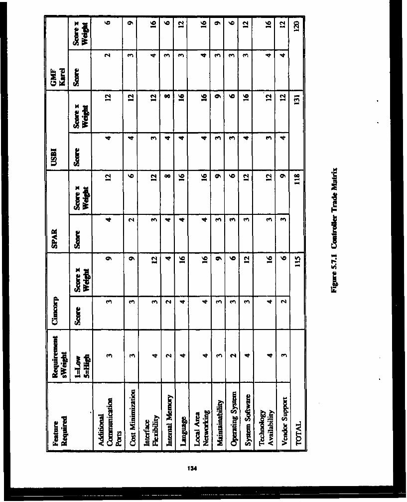
Nj~~~% N0 R%- - -
N OO C 0% %a 0-
C 4 m m m -m m
iil "
eql lo q m i
a'
ILI A
134

6.0 Conceptual Design
This section presents the conceptual design for the selected robot system, sensors,
controller, laser, and operational scenario. The counterbalanced telescoping beam
mounted on a heavy-duty tractor tug was selected as the most feasible representative
candidate. Based on the trade-off in section 5.1, the robot would be controlled using
an in-house designed VME-based controller. The UTIL Model SMI 1-6/6 kW C02Laser will be located forward of the robot arm.
The selected system for the existing facility is the wheeled mobile vehicle with a
telescoping boom. It will accommodate the current floor in Building 2212 and will
not impact the facility. For a new floor in Building 2122, the selected concept would
still be proposed, although some of the subsystems would require additional attention.
The conceptual design for the current floor in Building 2122 is presented first, The
second section addresses any significant issues and impacts on this concept if a new
floor were installed.
6.1 Building 2122 - Existing Floor
The tollowing sections describe the conceptual design for Building 2122 as it exists.
6.1.1 Robot System, This system utilizes a standard flight line transport with a
counterbalanced telescoping boom to position the work head around the aircraft, asshown in Figure 6,1.1, Ranges and travel speeds are projected for the mobile robot
system (MRS) and are shown in Table 6.1.1.
135

I - - - -- - - -
C.134 IN BUZLAZI@ 3112
Aan (car I ?NCLA1T.PE Ty" LA E
A%6~.1 MOTIO TZM4SA APS. OR~LAND"
IA061. 1 P#?ATI _MS "u.S 1N4AIO"10h
C(D C_
MW ILKE FtCOT gysM FOR LAM OOAINT?2,
m 0ow 0b
Ar~r m OWj. IC o&4

- -- - - --
---
_ __ _
U&l 111 0
iU. srms Fm.D U
M-44 Vt
,sw vvi: ouvw
LLA bWiS *eeQFS1 WAI'U- IwdIU
A --- 49:!= 1 ADOI AOIS
-,a~ 3i EW
Figure 6.1. Mobile Roo SsemfraeTI~igA AFU. SflJg
136

Table 6.1.1 MRS Ranges and Travel Speeds
Axes Name Type Range Speed
I BASE-i Rotational 3600 0-24*sec
3 ARM-1 Rotational 2000 0- lsec
Pitch
4 ARM-2 Translational 20-30' 0-6"Isec
5 ARM-3 Rotational 1800 0-60 /sec
Yaw
6 ARM-4 Rotational 1800 0-6*/sec
7 ARM-5 Translational 6-9' 6"/sec
8 ARM-6 Rotational 1800 0-1 0/sec
Pitch
With the boom extensions fully retracted, the reach of the robot is 26 feet. Axis
ARM-2 provides an additional 10 feet of reach when extended; ARM-5 contributes
an additional 3 feet of reach when extended. The highest reach required for the three
aircraft is 35 feet measured from the ground. For this particular scenario, only the
smaller 5-foot extension will be required.
Power requirements for the robot are estimated to be 480V AC, IOA, 60 Hz, 30 to
support the controller and electric motors. The vehicle diesel power supply would
need to be running to engage any of the drives unless an independent generator was
used. Since it is not feasible to run the diesel engine inside the facility, an umbilical
connection panel is provided on the side of the mobile robot system to be connected
to facility power and services or to a trailer generator system which would be located
outside the facility. The power and service trailer concept will allow the mobile
137

robot to travel between facilities regardless of facility power availability, A stow
position is provided for the robot arm during relocation.
The flight line tug is available from manufacturers such as Tug, Jetway Systems
and FMC. The tug is designed for heavy-duty operations and provides steel
section weldment unibody construction. Typical specifications are shown in
Table 6.1.2.
Table 6.1.2 Typical Tug Speciifcations
Engine
Model 8.2 liters turbo charged
Type Four-cycle V8
Displacement 500 cubic inches
Horsepower 205 HP at 2800 RPM
Torque Rating 442 ft. lbs. at 1700 RPM
Fuel Capacity 34 gallons
Travel Speeds J 0-15 mph
The beam delivery system method was not considered (luring the evaluation of the
robot alternatives, Owing to the nature of the concepts (i.e., all would require a
design effort), it was assumod that the beam delivery system could be integrated to
any robot system. The selected concept can incorporate an internal, external, or
hybrid beam system. The system can be run internally through the chassis of the tug,
up through the. rotation.l base of the robot arm and down the telescoping boom.
Motor and drive mechanisms for the telescoping boom would need to be located so
138
that they do not interfere with the beam delivery system. The beam could be run
externally from the laser to the work head. The scrubber system vacuum hose can
follow the robot arm externally in a similar fashion.
6.1.2 Sensor Systems. The selected sensor systems for collision avoidance, contour
following, color discrimination, and global locating are presented in the following
sections. Examples of product literature on the selected sensors are provided in the
Appendix.
Contour Following and Collision Avoidance. Several ultrasonic and laser-gauge
systems can be used. These systems will provide noncontact methods of contour
following and collision avoidance. Ultrasonic systems which can be used include the
following:
A. Ultrasonic Arrays DMS-1000 - This system provides measurement accuracies to
within 10.001 inches, Surface color texture and reflectivity have no effect on the
accuracies of the system. The sample rate is 1800 time/second.
B. Cleveland Machine Controls Pulsonic System - This system used ultrasonic
technology to produce a coherent column of sound. The pulsonic uses a discrete
pressure wave with only one highly repeatable pulse. It continually compensates
for speed of sound variation with a calibration bar mounted to the front of the
sensor. The sensing range is 2.5 to 40 inches, with a repeatability of 1-0.05% of
the range. The sampling rate is 800 times/second.
C. Staveley AG-101 - This system uses a state-of-the-art ultrasonic transducer to
provide distance measurement and profiling. Sample rate is 500 times/second
with accuracies of 10.002 inches or 0.1% of the range. Sensing ranges are 1 to
120 inches.
Laser gauge systems which can be used include the following:
130

D. Medar MDC-250 - USBI is currently using a Medar MDC-250 for this
application in its robotics laboratories. This microprocessor-bases, solid-state
gauging device scans with- low-power infrared laser-based light across the featureto be gauged, and calculates the feature contour based on the light
reflected/scattered back to the sensor's CCD detector array. Each scan is a
collection of individual measurements. The sensor can be used to maintain a
constant standoff and orientation to the surface of the aircraft.
E. Chesapeake Lasers LTG-2100 - This sensor provides a measurement range of
1 to 25 inches, with an accuracy of 0,1% of the range. The microprocessor is a
proprietary high-speed data acquisition device providing direct coordinate data
output.
Color Recognition Sensor, The color recognition system would be specifically
designed to provide color recognition for a limited number of pretaught colors. Thesystem must provide reliable answers at least at a 6M0 Hz rate. In general, therequired color sensitivity will dictate how many different wavelengths arecharacterized. The detector integration time is preset by the cycle time. Thus, the
only free variable is the illumination intensity, which must be bright enough toprovide enough signal-to-noise ratio for reliable measurements under all process
conditions.
Global Locating. Use of a vision system for global locating will be necessary todefine the robot's orientation with respect to the aircraft and generate rough path
trajectories. Although vision systems suffer from slow processing speeds, use of thevision system for edge tracking is the only application in which processing speed is a
factor. Even in edge tracking, slower processing speed does not severely impact
system performance. The vision system capable of handling the global locatingrequirements, as well as edge tracking and collision avoidance tasks is the Silicon
Graphics 4D/210 GTX Graphics Supercomputing Workstation with the Live Video
Digitizer option. While this system has not yet been proven, initial research indicates
140

that it is feasible. This workstation provides high-resolution real-time graphics which
can be integrated with the workstation software to provide visual simulation, image
processing, and animation. Special graphics processors allow computational and
graphics tasks to run simultaneously at full speed, providing the capability of real-
time visual interaction with applications.
6.1.3 Controller and Software. The block diagram in Figure 6.1.3 shows the
relationship of the controller with the system. The host computer workstation can act
as the main operator interface for monitoring and controlling the controllers and any
facility/support equipment processors during all on-line production operations.
Complete 3D cell simulation and robot off-line programming capability can be
provided with a separate CAD workstation.
The controller will communicate to the host computer and the off-line CAD
workstation over an Ethernet local area network. A machine-vision system computer
and a PC computer are ncluded on the network. The PC computer can be interfaced
on a separate network to all facility and process support equipment, programmable
logic controllers (PLCs), and can act as a central operator station. Special cameras
and sensor systems needed for globally locating the aircraft, mapping the structure,
and performing collision avoidance functions would be incorporated into a machine
vision system or work head or would be mounted to the arm as needed.
Controller. The robot controller would be a multiprocessor-based continuous path,
multitasking i'nit to handle simultaneous control of the 7-axis robot. In addition, the
controller would control and concurrently monitor various digital and analog work
head or process equipment I/O. Programming for the robot controller can be
generated off-line at the CAD workstation or on-line at a PC-compatible computer.
The work cell controller design incorporates two 68030 processors, a 68882 co-
processor, and open-architecture VME-based bus and 8-MB of RAM. The operator
141

I,.1
I/
I
U
I II6
I
142

interface PC computer would be an 80386-based VME bus by a high-speed data bus.
In addition to the gh-level robot programming language, software allows direct
access to the in-process robot program from the host computer and a communication
interface for the Ethernet local area network. The work cell controller is linked to
the robot through a high-speed serial link. A teach pendant and end effector 1/0 is
also connected to this remote robot interface.
Process Equipment Programmable Logic Controllers. The following basic
requirements exist for programmable logic controllers.
A. Programmable logic controllers (PLCs) should provide monitoring and control of
the various work cell support process equipment 1/0 and general facility
requirements.
B. All facility-related equipment that supports the entire cell (such as the water
reclamation system, door interlocks, ventilation, and lighting) should be routed to
the single PLC.
C. PLCs should be provided for all process equipment.
D. Each PLC should utilize interchangeable digital and analog I/O modules and
should be capable of high-level math, logic, and communication functions, as
well as controlling its local 1/0, using standard ladder logic.
E. Each PLC should be networked together via a separate data highway to a PC
computer which would act as the central operator interface for on-line/off-line
SPLC programming, program storage, diagnostic and alarm displays, and remote
access to and control over all system 1/0.
143

F. Any required communication and data transfer between the host computer 2nd
the PLC network computer should be handled first through the PC computer over
the Ethernet and then over the dedicated PLC network.
Host Computer Workstation. The following basic requirements exist for a host
computer workstation.
A. The host computer should be a 3D CAD workstation with multitasking and
multimode graphics capability which acts as the main operator station during all
in-process operations.
B. From the host computer -erminals, operators should be able to interact with all
work cell robots and process equipment controllers to provide a controlled start-
up and shutdown, to modify operating parameters, upload/download or store files,
and to print historical reports.
C. Critical in-process data displays and error control should be provided in a variety
of custom graphic displays that the operators can interact with.
D. Although a separate off-line CAD workstation is included, the host should be
able to perform 3D cell simulations and robot off-line programming if the need
arises.
E. The workstation should provide multiple 25 MHz RISC processors and co-
processors, a VME interface, large memory system disk, a minimum of 24 MB
of RAM, and both floppy and tape drives.
F. Standard software should include a UNIX operating system, C compiler, and a
communication interface for the Ethernet local area network.
144

Off-line CAD Workstation. The following basic requirements are presented for an
off-line CAD workstation.
A. Complete cell 3D CAD simulation and robot off-line programming capability
should be provided via a smaller workstation.
B. The operator should have the capability to enter or retrieve a CAD model of each
unique aircraft and then to retrieve or modify an already existing 3D CAD
simulation of the entire cell.
C. A robot software package for developing complete robot programs should be
provided.
D. Completed robot programs should be stored or uploaded/downloaded between the
workstation, the host computer, and controllers over tde local area network.
6.1.4 Laser System. The selected laser system is the UTIL Model
SMI-6/6 kw CO2 laser. The laser system comprises a modular gas circulation and
discharge section integrated into a single systemn with a common optical section and
control. Utility and service requirements for the system are listed in Figure 6.1. 1. A
complete specification is provided in the Appendix. The laser is shown in
Figure 6.1.4.
6.1.5 Operational Scenario. The operation begins with positioning the aircraft
into Building 2122. The robot system is positioned to the first processing location.
The global locating process is then performed to orient the robot to its position
relative to the aircraft. One of three processing approaches could then be used:
A. The surface area would be mapped using a mapping sensor system which inputs
data points into a path program. This program is then used to guide the robot
through its motions.
145
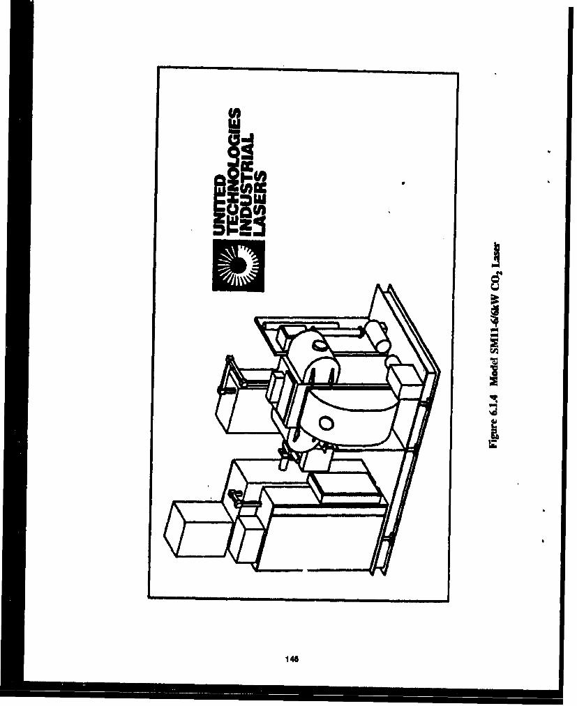
I0
a
146

B. A prewritten path program would be used based on off-line CAD data of theairplane. The robot would then follow this off-line program with sensors
adjusting for variances between aircraft.
C. Real-time'surface following and collision avoidance techniques would be totallyresponsible for the robot path.
After processing is performed on this area, the robot would be moved to the secondprocessing location. Based on the concept presented in this section, the robot wouldbe moved six times for each of the aircraft, as shown in Figure 6.1.5.
The preferred operational concept would incorporate method B, above, This methodis presented in the following sections.
Global Locating and Surface Mapping Process. Each time an aircraft enters thebuilding for paint stripping, Its approximate 3D positional location with respect to therobot must be determined so that program offsets can be generated. A gross surfacemapping process would then be performed with the ,'enerated data used to modify,plan, and verify the final robot trajectories and paths for the paint removal process.
Aircraft Positioning. The aircraft would be towed into the facility by a standardaircraft tug. The aircraft can be placed on jacks, or left on its wheels. If the aircraftis on jacks, the landing gear can be retracted to provide access to the underbelly.
Process preparation. Vision targets would be attached at key specific locations onthe aircraft. The off-line CAD workstation computer, machine vision systemcomputer, and any extra structural lighting will be turned on.
Global locating procedure. From the off-line CAD workstation, the operator wouldcall up the model of the aircraft in the facility in its optimum location for roboticprocessing. The machine vision system would begin running the global locating
147
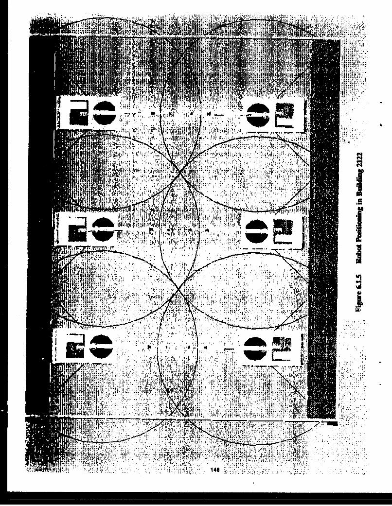
ij 1,44
""., lit
* It NA ~ u~j 1 1 ; K
at 1.1~ *. .. , ;,~4d ' ~rr ¶cr s't
* I'
qi 1481
1484

software to determine the orientation deviation of the actual plane location compared
to the model. The orientation deviation offsets would then be used to first verify theaircraft is within locational tolerance for processing and then to refine the working
3D CAD model of this specific aircraft (if this information is being maintained),
Mapping.path generation (optional). If used, the surface mapping procedure would
adequately define the local aircraft surface contour relative to the robot work
envelope. Using the working model of the cell genirated from the locatingprocedure, the operator would download the rough robot mapping programs to the
robot. After mapping, the final robot programs will be generated at an off-line CAD
workstation and then transferred to the host computer for storage. After the processis started, the operator would download robot programs as required from the host
computer to the robot. If a database is being kept on all aircraft, and if the aircrafthas not been in before, the CAD file associated with the aircraft would be the default
for the aircraft type.
6.1.5.2 Paint Removal Process. The removal of old paint, primer, and decals would
be performed, using the high power CO2 laser system. The System will be capable
of removing paint at a rate of 120 to 240 square feet per hour (based on the
requirement of 2-4 square feet per minute).
Process preparation. Controls and computer equipment would be turned on by the
operator. The robot will move to the start location. The system would beginmonitoring the depainting process equipment. Any protective masking necessary
(i.e,, for protecting cargo door seals or window seals) would be done before processstart-up, A different color masking can indicate to the paint/substrate discriminating
sensor that no pulse should be provided by the laser system. The laser system would
be readied for use,
Process perfori, ance. During the stripping process, the robot would follow thepreprogrammed path for the specific aircraft, possibly updated through mapping,
149

Nominal standoff will be maintained by the surface-following sensor. The
palnt/substrate discriminating sensor would report on removal status. Collision
avoidance sensors would be operating. Edge detection would keep pulses from being
generated without a target. The waste collection system would collect paint debris
for disposal. After processing at this position, the robot would home itself and the
system would move to the next processing location.
6.1.6 Facility and Safety Considerations. Steady-state or cyclic noise produced
by machinery equipment measured at the operator's position in the control room
should not exceed 85 decibels. Operators are prohibited in the work cell during paint
removal operations because of the Class IV designator assigned to the laser system
by OSHA. The robot system and its process equipment should not create a chemical,
physical, or biological hazard to operators or other employees. To eliminate potential
health hazards, exhaust ventilation, protective guards, and filters are used.
Warning signs placed in the facility should conform to OSHA (and NFPA-70)
requirements (see OSHA 1910.145 for definitions, colors, symbol for danger, and
examples):
DANGER red, black and while
CAUTION yellow and blackSAFETY INSTRUCTIONS green and white
The locations of warning signs should be chosen carefully to assure that hazards are
clearly marked with the safety cover removed or attached.
6.2 Building 2122 Issues and Impacts - New Floor
Since the selected concept for the existing facility can easily be incorporated onto the
new floor, no new requirements are derived. The new floor, with a smoother finish,
will only enhance the performance of the robot system.
150
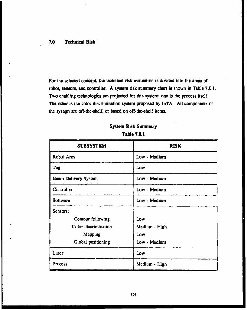
7.0 Technical Risk
For the selected concept, the technical risk evaluation is divided into the areas of
robot, sensors, and controller. A system risk summary chart is shown in Table 7.0.1.Two enabling technologis are projected for this system; one is the process itself.
The other is the color discrimination system proposed by InTA. All components of
the system are off-the-shelf, or based on off-the-shelf items.
System Risk SummaryTable 7.0.1
SUBSYSTEM RISK
Robot Arm Low - Medium
Tug Low
Beam Delivery System Low - Medium
Controller Low - Medium
Software Low - Medium
Sensors:
Contour following Low
Color discrimination Medium - High
Mapping Low
Global positioning Low - Medium
Laser Low
Process Medium - High
151

7.1 Robot and Controller
The risk associated with the robot arm is low to medium. The counterbalanced,
telescoping arm technology incorporated in this conceptual design has been proven in
several applications. In a situation where large-scale robotics are needed, however,
the challenges must be accepted.
The risk associated with the tug is low. A standard unit will be modified to meet the
requirements of the robot arm and laser system. The beam delivery system is rated
as a low to medium risk because of the number of mirrors that will be required.
However, the technology for beam delivery is well established for both internal and
external systems.
The controller is evaluated as a low to medium risk because of the need for an in-
house designed system to accommodate the specifics of the robot system. Software
is always a potential problem area.
7.2 Sensors
All sensor equipment specified is readily available for procurement. The selected
sensors are already performing the similar operations in other applications.
7.2.1 Contour Following. Little risk is associated wvith the contour-following
system. These are being used extensively in other applications.
"7.2.2 Color Discrimination. The color discrimination sensor system is assigned a
higher risk because of the responsibility it has for not allowing the laser to damage
the aircraft and because of the feedback rate requirements. If the InTA system
proves to be feasible, then this risk is significantly reduced.
7.2.3 Mapping. If this function is used, it will be similar to several applications in
industry, The risk associated with this process is low,
152

7.2.4 Global Positioning. Machine vision has been proven in industry. Use of
the SOI system and video digitizer are not proven specifically; hence, the low to
medium risk.
7.3 Lasers. Lasers that can N used are standard commercial products today and
represent a low technical risk. (See Appendix.)
7.4 Process. The laser paint stripping process has not been proven beyond test
panels in a laboratory and is rated a medium to high risk.
153

8.0 Program Plan
A draft Work Breakdown Structure for an ALPS system is presented in the followinglist. This top level WBS will need to be broken out into the lower levels prior to
beginning the effort.
Most of the cost associated with "1.0 Design" is labor. The majority of material
costs would be incurred in "2.0 Fabrication."
Work Breakdown Structure
1.0 Design
1.1 Robot System
1.1.1 Robot Arm1.1.2 Tug
1.1.3 Power and Service Trailer
1.2 Laser System
1.2.1 Laser
1.2.2 Workhead
1.2.3 Beam Delivery System
1.2.4 Scrubber System
1.3 Computer Hardware
1.3.1 Host Computer
1.3.2 Controller
1.3.3 Off-line Workstation
184
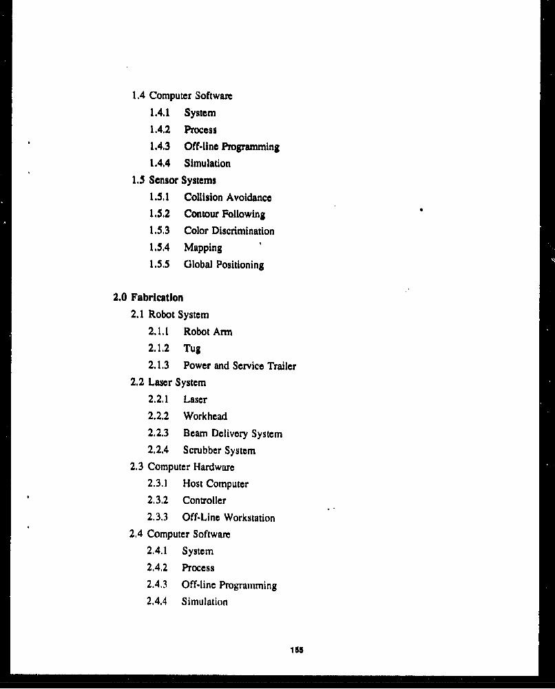
1.4 Computer Software
1.4.1 System
1.4.2 Process
1.4.3 Off-line Programming
1.4.4 Simulation
1.5 Sensor Systems1.5.1 Collision Avoidance
1.5.2 Contour Following
1.5.3 Color Discrimination
1.5.4 Mapping
1.5.5 Global Positioning
2.0 Fabrication2.1 Robot System
2.1.1 Robot Arm
2.1,2 Tug
2.1.3 Power and Service Trailer
2.2 Laser System
2.2,1 Laser
2.2.2 Workhead
2.2.3 Beam Delivery System
2.2.4 Scrubber System
2.3 Computer Hardware
2.3.1 Host Computer
2.3.2 Controller
2.3.3 Off-Line Workstation
2.4 Computer Software
2.4.1 System
2.4.2 Process
2.4.3 Off-line Programming
2.4.4 Simulation
155
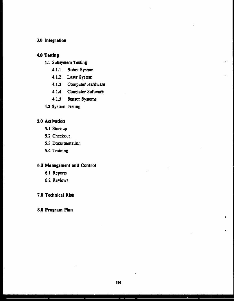
3.0 Integration
4.0 Testing
4.1 Subsystem Testing
4.1.1 Robot System
4.1.2 Laser System
4.1.3 Computer Hardware
4.1.4 Computer Software
4.1.5 Sensor Systems
4.2 System Testing
5.0 Activation
5.1 Start-up
5.2 Checkout
53 Documentation
5.4 Training
6.0 Management and Control
6.1 Reports
6,2 Reviews
7.0 Technical Risk
8.0 Program Plan
16

AUTOMATED LASER DEPANMTING OF AIRCRAFT
SURVEY OF ENABLING TECHNOLOGIES
Appendix
Peter W. KopfDean Pichon, et al.Arthur D. Little, Inc.25 Acorn ParkCambridge, MA 02140-2390
Jiauary 199'
Final Report for the Period May 1989 to January 1991
Approved for public release; distribution unlimited
WRIGHT LABORATORYMATERIAI.S DIRECTORATEAIR FORCE SYSTEMS COMMANDWRIGHT-PATTERSON AIR FORCE BASE, OHIO 45433-6533
157
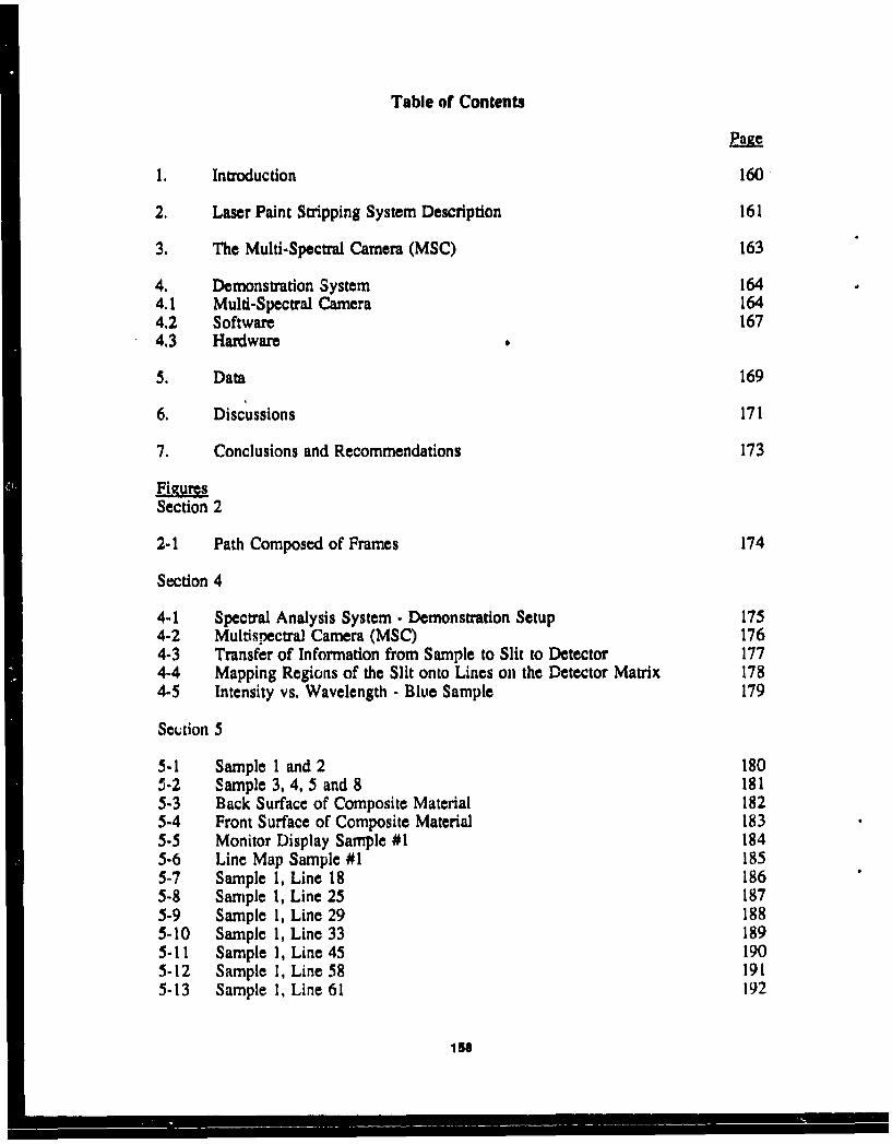
Table of Contents
Page
1. Introduction 160
2. Laser Paint Stripping System Description 161
3. The Multi-Spectral Camera (MSC) 163
4. Demonstration System 1644.1 Multi-Spectral Camera 1644.2 Software 1674.3 Hardware
5. Data 169
6. Discussions 171
7. Conclusions and Recommendations 173
Fig~uresSection 2
2-1 Path Composed of Frames 174
Section 4
4-1 Spectral Analysis System - Demonstration Setup 1754-2 Multispectral Camera (MSC) 1764-3 Transfer of Information from Sample to Slit to Detector 1774-4 Mapping Regions of the Slit onto Lines on the Detector Matrix 1784-5 Intensity vs. Wavelength - Blue Sample 179
Section 5
5-1 Sample 1 and 2 1805-2 Sample 3, 4, 5 and 8 1815-3 Back Surface of Composite Material 1825-4 Front Surface of Composite Material 1835-5 Monitor Display Sample #1 1845-6 Line Map Sample #1 1855-7 Sample 1, Line 18 1865-8 Sample 1, Line 25 1875-9 Sample 1, Line 29 1885-10 Sample 1, Line 33 1895-11 Sample 1, Line 45 1905-12 Sample 1, Line 58 1915-13 Sample 1, Line 61 192
156
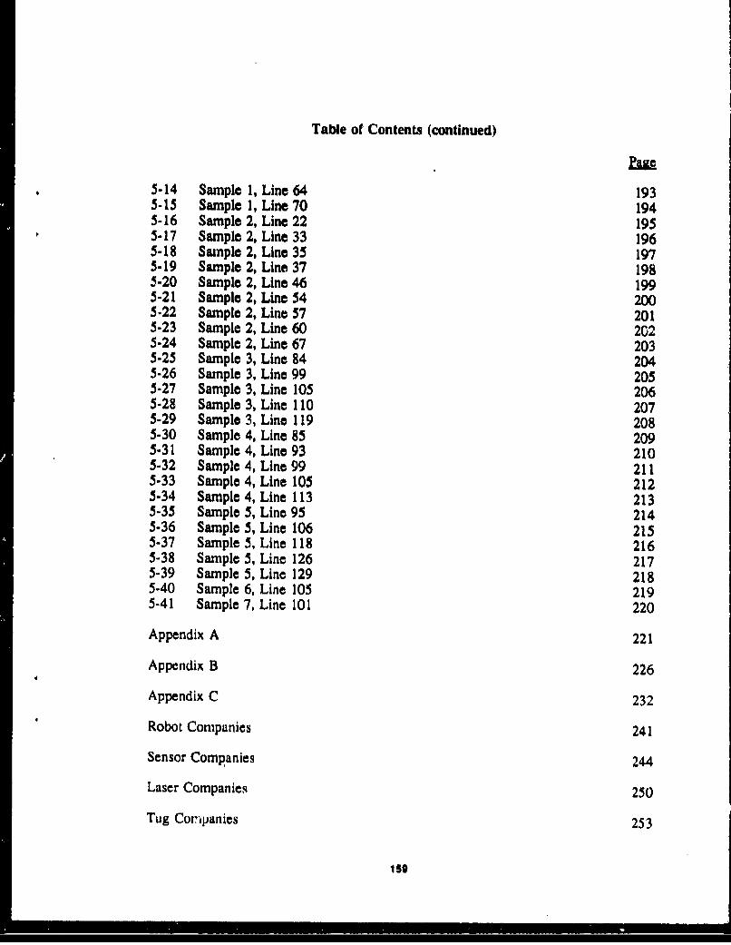
Table of Contents (continued)
5-14 Sample 1, Line 64 1935-15 Sample 1, Line 70 1945-16 Sample 2, Line 22 1955-17 Sample 2, Line 33 1965-18 Sample 2, Line 35 1975-19 Sample 2, Line 37 1985-20 Sample 2, Line 46 1995-21 Sample 2, Line 54 2005-22 Sample 2, Line 57 2015-23 Sample 2, Line 60 2025-24 Sample 2, Line 67 2035-25 Sample 3, Line 84 2045-26 Sample 3, Line 99 2055-27 Sample 3, Line 105 2065-28 Sample 3, Line 110 2075-29 Sample 3, Line 119 2085-30 Sample 4, Line 85 2095-31 Sample 4, Line 93 2105-32 Sample 4, Line 99 2115-33 Sample 4, Line 105 2125-34 Sample 4, Line 113 2135-35 Sample 5, Line 95 2145-36 Sample 5, Line 106 2155-37 Sample 5, Line 118 2165-38 Sample 5, Line 126 2175-39 Sample 5, Line 129 2185-40 Sample 6, Line 105 219
5-41 Sample 7, Line 101 220
Appendix A 221
Appendix B 226
Appendix C 232
Robot Companies 241
Sensor Companies 244
Laser Companies 250
Tug Companies 253
150

R-InTA-90-2/3
1. INTRODUCTION
Laser Paint Stripping (LPS) offers the opportunity to reduce the costof de-painting aircraft as well as to eliminate an environmentally unacceptableprocess, The InTA approach to LPS uses a pulsed laser and spectroscopic feedbackcontrol. The feedback is provided by a special spectrometer and sensing elemeit,called a multispectral camera (MSC). This report describes a cost shared programbetween A.D. Little and InTA to demonstrate the elements of the MSC. Aspectrometer, sensor an8l frame grabber were purchased, assembled and
demonstrated. The demonstratain was held on 30 May 1990.
160

R-InTA-90-2/3Page 2
2. LASER PAINT STRIPPING SYSTEM DESCRIPTION
LPS involves a laser ablation process, a laser delivery system, a
feedback control system, a positioning system and a waste removal and processing
system. It Is not sufficient to develop a successful laser paint removal proces,.The
entire system must be successfully developed and integrated.
The InTA laser ablation process utilizes a pulsed CO laser operating
with a peak power between 50 kW and I MW, a pulse width between 20
microseconds and 30 microseconds (FWHM), and an energy of 5 J to 6 J per pulse.To achieve a coating removal rate of 4 sq. ft/mmn. requires average of 6 kW of
laser power which at 6 3/pulse, requires 1000 pulses per second. To maintain a low
average power density (watts/cms) impingement on the coating the pulsed laser
beam must be moved rapidly. The method chosen to achieve this low power
density is a raster pattern of 30 laser pulses across and 30 laser pulses down. This
raster pattern, called a "frame," therefore has 900 laser "footprints" covering
approximately 1.0 sq. ftM (see Figure 2-1). With the laser operating at 1000 pulses
per second it takes the system 0.9 s to complete one pass over the pattern. If 6 J
per pulse is delivered to the coating removal surface, the average power density is
6.7 W/cm2. A standard paint coating thickness averages 3.0 mils. Each pass over
the frame removes approximately 0.3 mils (300 micro-inch) of paint, therefore, ten
passes are required to remove all the paint within a frame. These ten passes
require 9 seconds for a peak paint removal rate of 6.7 ft 2/min. Another common
method of expressing the removal rate is in square feet per mil of removed paint
per hour, In these units the peak removal rates are 1200 ft 2/mil/hr.
As shown in Figure 2.1, the rastering operation then moves to the
next (overlapping) frame.
To provide the feedback control, a spectrometer must determine the
color of each footprint and decide if that color is to be stripped. This process
must be carried out at the rate of 1000 decisions per second. To further improve
the system's ability to properly categorize each footprint color, the footprint is
divided onto four segments, each approximately 2.5 mm wide by 10 mm high. All
four spectra from a footprint must match the allowed spectrum for the foo.print to
161J

R-InTA-90-2/3Page I
be processed, Thus 4000 decisions per second are required with each decisionrequiring up to 20 comparisons to various allowed and disallowed spectra. Up to80,000 spectra comparisons per second may be required. This computationalintensive task will be carried out by array processors.
162

R-InTA-90-2/3Page 4
3. THE MULTI-SPECTRAL CAMERA (MSC)
The camera consists of a lens system, a flat field spectrometer and a
two dimension 256 x 256 element sensor. The camera electronics includes the
digitizer and the memory to store each digitized frame.
The camera is equivalent to 256 single spectrometers. This allows an
entire frame row to be processed simultaneously. The frame row (path) consists of
30 footprints, each of which is examined over four segments for a total of 120
areas. If every other spectrometer is utilized and eight of the remaining
spectrometers are used for normalizing ambient light then 120 spectrometers are
available to process the row. This approach improves the processing throughput
since the data transfer overhead is a major source of processing time. In addition
array processors perform best when they process many identical calculations
simultaneously.
The spectrometer selected for the demonstration was a model lOOs
from American Holographic (see Appendix A). The sensor was a model MC9256
from E G & 0 Reticon (see Appendix B). The frame grabber was a model MV-I
from MetraByte (see Appendix C).
163

R-InTA-90-2/3Page 5
4. DEMONSTRATION SYSTEM
The equipment for the demonstration system is shown in Figure 4.1.
In the demonstration system, the color sample is positioned on the sample table so
that a region of interest is imaged on the slit. No scanner is needed for the
demonstration tests.
The electronics and data reduction allow for storing, analyzing and
identifying various colors, and for comparison against stored sequences of spectra.
The following sections describe the Multi-Spectral Camera (MSC), the
software for control and analysis, and the electronic hardware of the
demonstration system.
4.1 Multi-Spectral Camera (MSC)
The components of the camera are detailed in Figure 4.2. The major
elements are:
Sample TableLight SourceImaging LensSpectrometer SlitHolographic Grating2-Dimensional Detector Array
For the present experiments it is not necessary to scan the sample, so
that color samples may be placed on a horizontal table surface and positioned by
hand.
Two light sources were employed in the tests - one, a xenon strobe,
and the other a continuous xenon arc lamp. The data presented in a later section
was taken with the continuous source. The light is arranged to shine down on the
sample at a small angle to vertical, which prevents specular reflection and at the
same time maximizes light collection at the lens.
154
L I I I ii I I

R-InTA.90-2/3Page 6
The imaging lens, a 50 mm FI.8 photographic objective, create$ an
image of the sample at the slit plane. Magnification is I/SX. Only that portion of
the image which lies within the slit is re-imaged on the detector. Since the slit is 5
mm x 50 um, the corresponding sample area visible to the system is a rectangle 40
mm x .04 mm.
The holographic concave diffraction grating is equivalent to a 97
mm F2.2 lens. It performs two functions; it disperses light from the slit rectangle,
and images it on the detector.
One-to-one imaging is used in this arrangement for 35nm/mm
dispersion at the focal plane. The grating is capable of 190nm-1065nm operation,
With the limited detector size, we can choose a coverage of 330nm anywhere within
this range (e.g. 375nm-705nm) across the detector.
The detector itself is a 256 x 256 silicon array with pixel-to-pixel
spacing of 40um. It has a fairly linear reaponse from 400nm-700nm, with a
relative responsitivity within this range of 0.4-1.0 respectively. Spectral resolution
is 1.4nm/pixel, and array saturation energy is 0.4uJ/cms,
Figure 4-3 shows the transfer of information from the sample to the
slit to the detector. The reflectance spectrum (R(A)) of the sample; is used to
identify the sample materials, the function of the MSC is to generate appropriate
reflectance spectra for analysis and comparison to known spectra. This requires
that we illuminate the sample and then, measure the spectrum of the light reflected
from each visible element of the sample.
Starting with the slit size and magnification, we can say that the
visible portion of the. sample is a rectangle 40 x .04 mm.
At the receiving end of the system, the detector matrix is 256 x .04
10.24 mm square - and the slit is imaged on this detector with a magnification of
IX, Then each detector (40 x 40 urn) sees a 40 um high portion of the slit, hence a
.32 mm high portion of the sample (at 8X). But light from each 40 um high "cell"
105

R-InTA-90-2/3Page 7
of the slit is spread across the entire width or the detector by the grating,
dispersed according to Its wavelength. The 5 mm slit is converted to a 5 mm high,
stack of spectra, occupying 5/.04 - 125 of the 256 detector lines.
Figure 4-4 shows how the "cells" of the slit map onto the detector
matrix. These are not physically separate, of course, but simply regions of the slit
space, divided to show where the energy goes after dispersion. The position of the
image data on the detector is arbitrary - the Image can be tilted vertically, to
occupy any 125 of the 256 lines; or it can be tilted horizontally to bring any
wavelength group onto the detector. We have shown an image beginning at line 4,
ending at line 129, and set so that light of wavelengths from 350 to 680 nm falls
on the detector matrix.
The data stored in each pixel of line is proportional to the spectral
reflectance (R( X)) of the corresponding point on the target material. Therefore,
for a given line, we can generate a curve of (R(,\) vs , from the stored light
level, (R) and the corresponding column number, representing wavelength > . A
sample curve is shown in Figure 4-5. Curves from the actual samples are collected
in Section 5, Data.
Figure 4-5 shows raw data from a blue region of the sample. On the
same graph, we have plotted background spectral data. The difference between
these two is also shown, as a corrected spectral curve. The edge-of-field peak
contains no information about the sample; it indicates the end of the spectral scan.
In the demonstration system, the operator can view the dispersed
pattern directly on the monitor. The presence of light at any point X, Y on the
monitor, position vs. wavelength, indicates that light of wavelength X is being
reflected by the target area at "slice" Y. The brightness is proportional to
reflectance at that wavelength. The entire frame of information is saved and
processed by an efficient algorithm to yield material identification data.
106

R-InTA-90-2/3Page 8
4.2 Software
MetraByte's VOS (Vision Operating System) offers a user-friendly
programming alternative for MetraByte's MVI Frame Grabber. An icon-based
program, VOS, allows one to select and modify the analog front end settings for
the board, and to acquire and modify frames of video data.
All functions of VOS are easily accessed using the keyboard or a
mouse. Other pointing devices which are supported include tablets, trackballs, and
lightpens. VOS allows you to easily perform such functions as: set/changilng the
MVI's parameters, add/define objects, manipulate Look-Up Table (LUT) settings,
and adding text. Additionally, VOS features an extensive on-line Help. These
windowed screens can be enabled or disabled with the click of a button.
Another feature of VOS is its Record/Playback function which can
be activated to record all point and drag operations, store them in a user-specified
file, and then be "played-back" from that file. This feature Is ideal for
automatically sequencing complex routines in applications ranging from repetitive
testing to self'-running demonstrations.
4.3 Hardware
MetraByte's MVI Fr.ame/Line Grabber is a 512 x 512 x 8-bit
frame/line grabber for real-time digital image processing on the IBM Personal
Computer XT/ATtm or compatible. The board digitizes an analog video signal,
stores the digitized image in one of the video memory banks, allows graphics and
text imagery to be added, and then displays the image in R-G-B psuedocolor or
monochrome at a rate of 30 image frames per second. If desired, the image can be
stored on a hard or floppy disk.
The MVI accepts monochrome video input signal from RS-170, RS-
330, or CCIR compatible sources. Input can be of interlaced or non-interlaced
format. Cameras with digital output may also be interfaced to the MVi.
167

R-InTA-90-2/3Page 9
The MVI features 512 KB of dual-ported video memory and an 8-bit
digitizer which achieves 512 x 512 resolution in 1/30 of a second. The MVI
supports a variety of system configurations and is equipped with the following
connectors:
o DB-15 for I/O of video, synchronization, and timing signals
o DB-9 Mllows display to analog, multisync monitors
o BNC for video sources
o 26-pin Digital I/O Interface
o 10-pin Timing Bus for multiple board applications
1 6
IlU II I I ini IN~ e N i . • , "" nil iiii i , ,, i

R-InTA-90-2/3Page 10
5. DATA
Eight samples were measured and recorded using the demonstration
system. They are:
01. Blue - Red - Green#2. Brown - Purple - Orange#3. Grey with Yellow Squares#4. Dark Green with Yellow Squares#5. Aluminum with Yellow Squares#6. Composite Back07. Composite Front#8. Painted Composite, Partially Stripped
Color prints of the samples are shown on the following pages. Figure
5-1 contains samples I (blue-red-green) and 2 (brown-purple-orange). In Figure 5-2,
the upper image is the partially stripped painted composite, sample 8, showing
various layers through the paint stack. The bottom Image is the aluminum plate
containing samples 3, 4 and 5. The composite back surface is shown in Figure 5-3
(sample 6), with a visible fiber texture. The smooth front surface of the composite
(sample 7) is shown in Figure 5-4. The appearance of sample I is shown in a
sketch of the monitor display, Figure 5-5. The corresponding line map is given in
Figure 5-6, to show regions of constant color and transitions between colors.
The curves of the various samplus (raw data - background -
corrected spectrum) show clear and distinct differences between the colors in any
one sample (e.g. between yellow and green, in sample 4). Furthermore, the
transition regions introduce no ambiguities of color. Given a set of colors for a
given task, we know the spectrum for each layer. At the interface between one
layer and the underlying layer, the transition spectrum is a weighted sum of the
two spectra, If K(n) is a weighting factor depending on line number n, and, for
example,
If the pure red spectrum is IR( )
while the pure blue spectrum is IB(,• ),
then in the transection region, the spectrum is:
K0(n) IR(a ) + K:(n)IB( X ):
169
R-InTA-90-2/3Page II
This is a predictable function, and the mixture of spectra in transition regions does
not compromise identification of the sample.
Samples I and 2 are obvious patterns, and the spectra are different
enough In each region to offer no difficulty. Samples with various greys and
neutral colors are more complex, and require more care in separation. Here, the
number of everlized spectral regions increases. Nevertheless, we were able to
establish clearly different spectra for all the different samples under test. Simple
inspection of the spectral curves reveals their unique spectral fingerprint.
A change in system light shielding greatly reduced background
energy and scattering. Samples I and 2 were measured before the change; samples
3 through 8 were measured after this improved shielding was installed. Since the
first two samples had clear colors and sharp boundaries, they yielded identifiable
spectra despite the scattered light. After the change, background light levels
dropped and transition regions became much sharper. These changes can be seen
in the curves for samples 3, 4 and 5. Transition regions for these samples were
only 3 to 4 lines wide, compared to the much wider transitions detailed in samples
I and 2.
The composite front and back look very similar to the eye, except
that the web texture is visible on the back. However the spectral curves shows a
definite difference in the 350-420 nri region, below the visible. This illustrates the
importance of selecting wavelength regions in the analysis of spectra.
Sample 8 is of special interest, because it is an actual sample of a
laser stripped material. Jeveral print layers are visible. The stripping process,
taking material off to continuously increasing depth, has itself wide transition
areas where material Crom two lIyers is visible in most regions. A definite yellow
region appears at line 88. On the sample, this color gradually changes to grey at
line 109. Here, the characteristic 'grey" peak appears at 450 nm. The sample then
cha~nges gradually to a brown, with an almost uniform reflectance across the
visible spectrum.
170

R-InTA-90-2/3Page 12
6. DISCUSSIONS
The experiment was two fold in purpose: 1. To show that a spectrum
could be easily produced, captured and identified; and 2. To show that transition
regions from one color to anotner can be analyzed without introducing ambiguities
into the identification process. Botb these demonstrations were successful.
The system hardware for illumingting the sample And dispersing
light will follow, in general, the laboratory set-up, but at an appropriate scale up.
The major change will be addition of a scanner mechanism to follow the raster
pattern, synchronized to the ablating lasers raster. For this task, we expect to use
conventional scanner hardware such as is used in InTA's other robotic and contour-
scanning devices.
Clearly, the light source must contain the wavelengths at which
samples exhibit their peak reflectance. A xenon arc lamp (whether strobed or
continuous) generates a continuum in the visible region, as well as considerable
short IR.
For any particular stack of paint layers, there may be some
advantage to removing certain wavelengths - those that are reflected equally by all
members of the stack. A filter can be inserted in the source for this purpose.
While it is certainly possible to remove common wavelengths electronically, it
should be done in the optics, if possible, where such a filtering operation can
improve the scatter and background at the same time.
Quality of the MSC components is more important in the final
system, where the caniera must operate in the presence of extraneous light sources
strobing will help on some of these problems. iFhe detailed design uf the grating
system must be studied to improve dispersion, redu.e line-to-line scatter, and
piovide the highest efficiency in the selected order.
171
R-InTA-90-2/3Page 13
The most important optical component in the entire system is the
sample itself. Its reflectance spectrum is the subject of the entire process. We must
also consider its spectral scattering properties and its specular reflectance - for
example, so that other light sources in the work area do not reflect from it into the
lens. A thorough study of the paints' properties will save money in hardware, time
in processing, and trouble with unwanted signal.
172

R-InTA-90-2/3Page 14
7. CONCLUSIONS AND RECOMMENDATIONS
On the basis of data collected for this program, it is clearly possible
to discriminate between different paints and substrates on the basis of their
spectral diffuse rfdlectance. The hardware to implement this process can be
assembled from commercially available components. The process can be completed
quickly enough to control a paint stripping laser scanner.
In a practical paint stripping system, the target area will be shielded
from direct room light by the shroud containment, so the background conditions
should be no worse than the laboratory system.
We believe that such a system can be built with a minimum of risk,
now that the basic detection mechanism has been proven. Improvements in speed
and in discrimination will continue as the software Is developed. Applications to
paint stripping, surface texturing and laser cleaning are already obvious. Any
laser process that modifies the spectral reflectance of a surface can now be
implemented and controlled with systems similar to this.
173

>
00
owU
LL.
* EU-EU I~i* lUM174
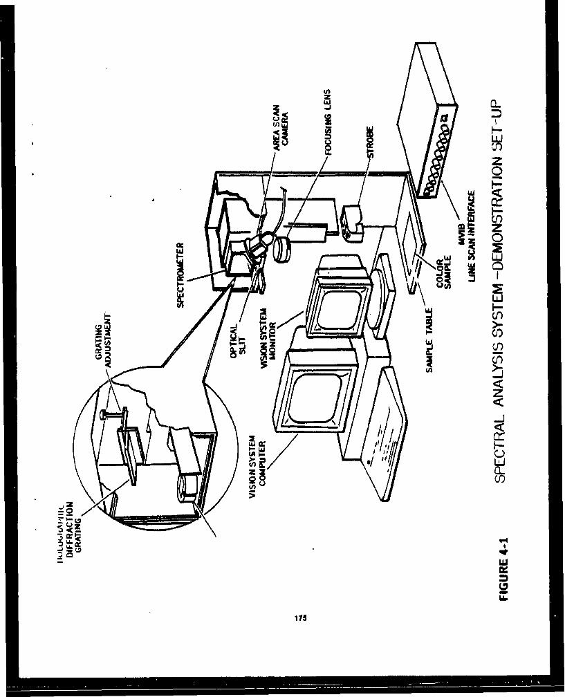
U))
LUL
z0
zz
Li
(n)
z-i
ui~
3 66
u.
175e

HOLOGRAPHIC CONCAVEDIFFRACTION GRATING
7 DISPERSED IMAGES~OF SLIT
SLIT (50UM) DETECTOR/CAME R A
IAEO SLIT HOLDER
COLOR SAMPLE
LENS STROBE
SAMPLESAMPLE TABLE
MULTI-SPECTRAL CAMERA (MSC)
FIGURE 4-2
I7O

96
= 016.
z ZLU
alw
zU-96
ww
Uj
170

94-
Iwo,
z f4
o ol
LU
L~Lb
LU00
I-
oN
0l1 -1 tu -
~uu W1uI

al.
001
z
0 C4
C3 4
wuH-M
A-IN .LI3 IYSi

I
Sample I
(Blue)
I
S.nmpLt 2
r( rjrp.,)
FilIuru 5-I
IGO

Figure 5-2
Sample 8
sample5
Sam~ple J sanipe~ .4
181

Figure 5-3
Dack surface of Composite Material
102

4I
AI
Flyure 5-4
Front surface of Composite MaterijI
183

MON/TOR DISPLAY SAMPLE # /
FIOUPE 5 -5 184
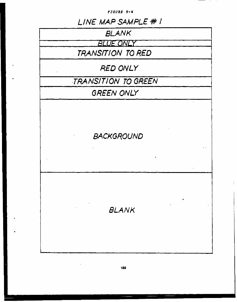
FIGURE 5-6
LINE MAP SAMPLE # I
BLANK
TRANSITION TO RED
RED ONLY
, TRANSI TION TO GREEN
GREEN ONLY
BACKGROUND
BLANK
185

S
rNN
LUJ
can 01-
.kJISN3.LNI 3NLV13W
Ise

Co
z
Ilk,'
94 L4
'C3
,UISNJ.LNI 2W.'Y"13W
Lm
187
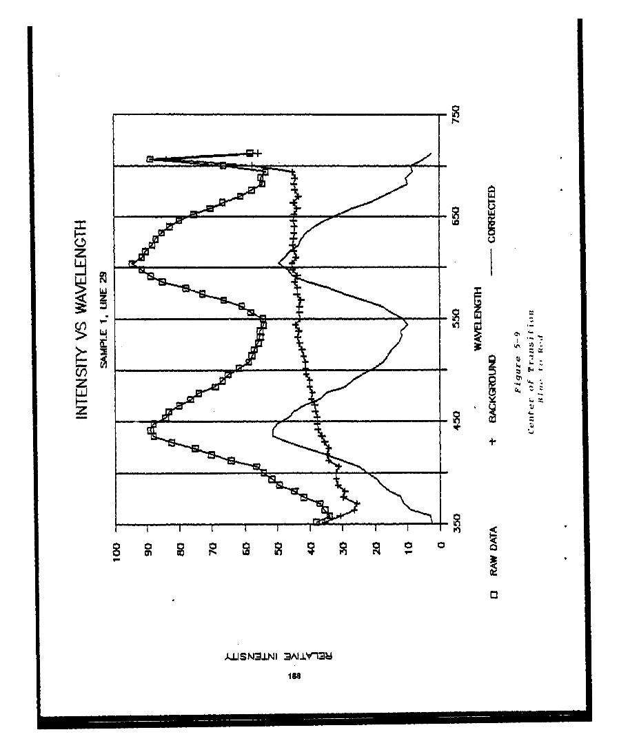
LUJ
z -
,UISN"A±NI 3A).Y13U
L m
le8
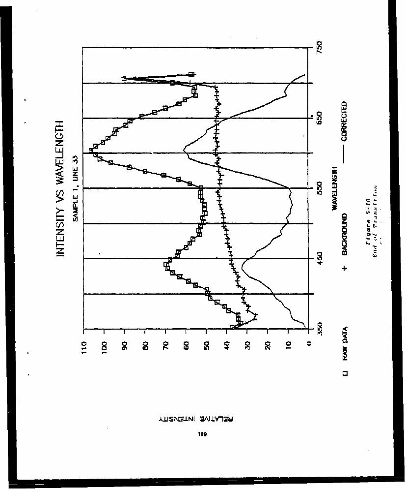
lz 4
z+
C,)3
ISO.

LIJJ
z
LMl
z
zM -4
190
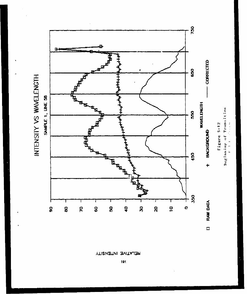
Z
£-USN3.LNI 3ALLY13A

F4-
0c
,US3LI NLlh
10

I 1.1.1
z
LJ
193-

194
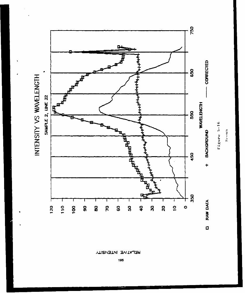
0 rrN
wri
L.I-.
)Ul.ISN.LNI 3A1 ±LY'13W
195

LOU
Ig
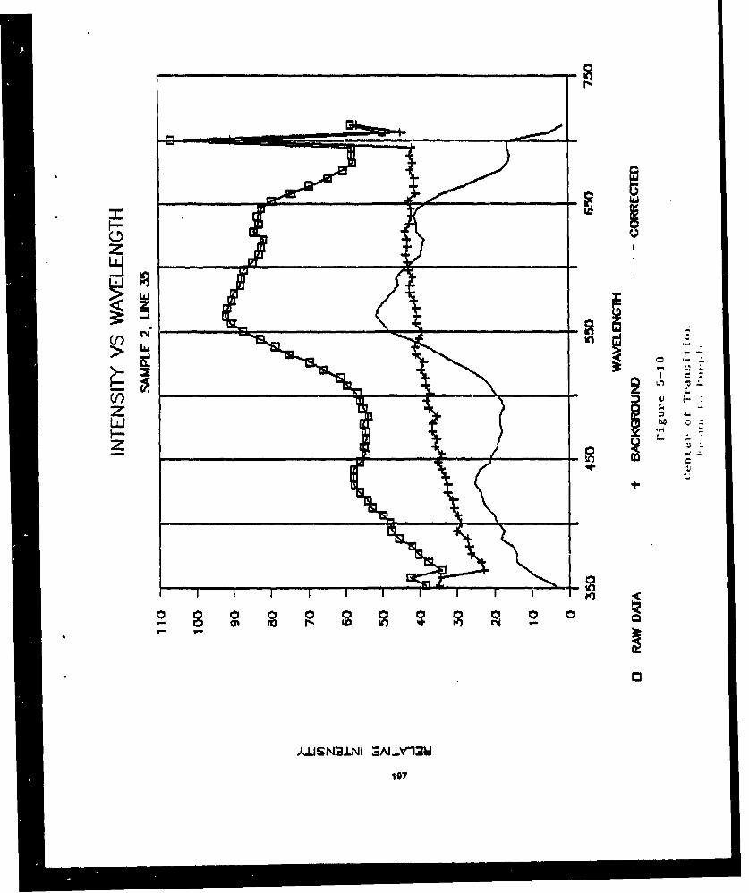
Iq
>0 L
zL i
Icon
A(f*)LN 3A LL 13
197

z
z
A.ILISN3.LNI 3NJlY13W
Igo
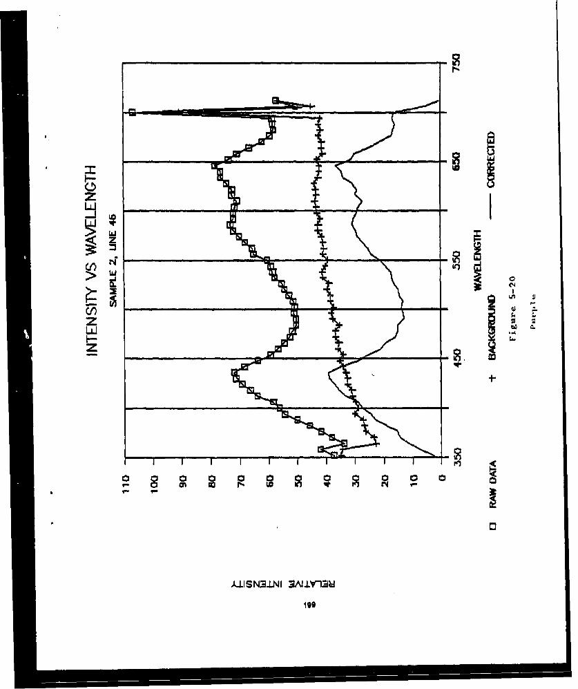
GO
"ti C
191-

:3iN4
w1
200

00
L6.
I-J
)LJJSN3J.NI 3AI.±V13
201

z
U.'
,UISN3.LNI 3N.±Y"GU
202

zs
Or,
LUl
-7-
£USN3.LNI NL~Y13U
203
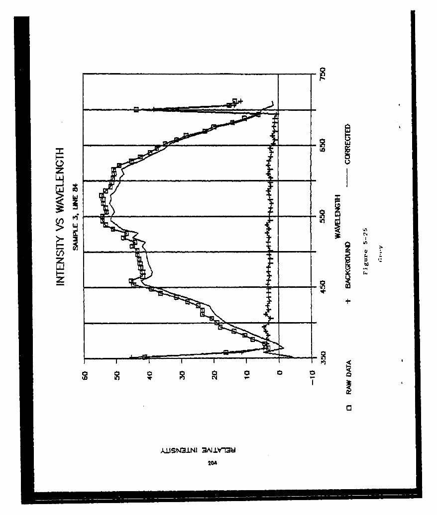
U3
zl
cf~o
M.z.wmH-2
204

us
zHL
con 0
I'.:
2050
d U S N ± N mA± 1

ý7-
zzLJ.
206
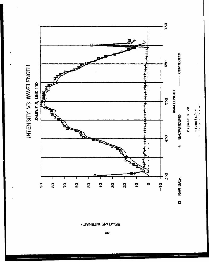
Li
0m 15. or 01-0 or
.111S N3±N I 3rJLrlMJ
207

I-I
0L
z+
206
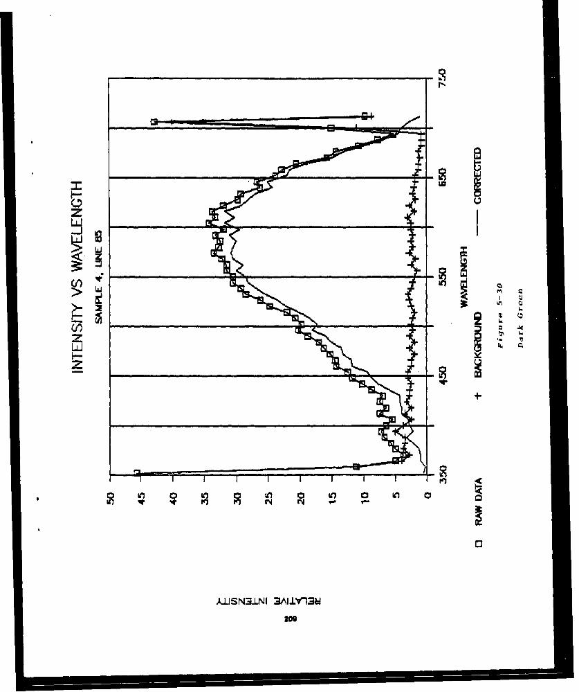
z>
'I:Iz'
A-LISN3.LNI 3AI.JY13U
log

zz -E
w4
210-

Iw
z
W Fn
)LS N3-NI 3ALLYMM
211

U3
z<
¾iS3.N 3AIY~~212

z
U5
og'- VO 4 1
213

0j
w
214-
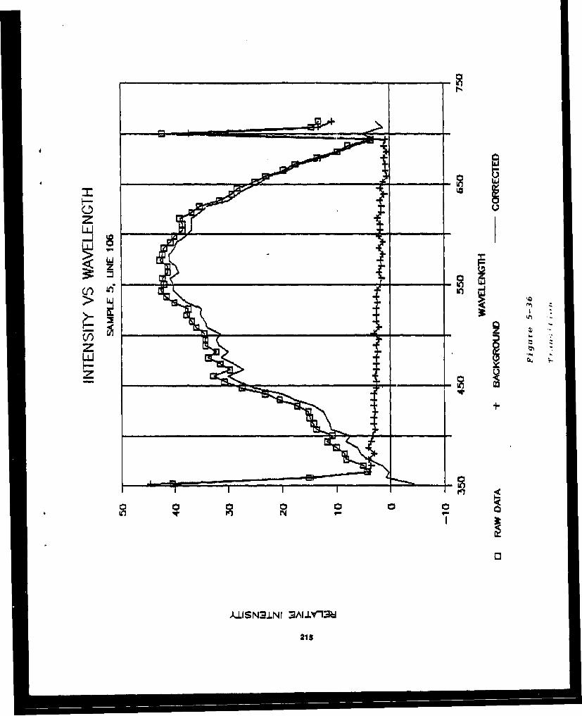
IW
z
LUIN3N ALYM
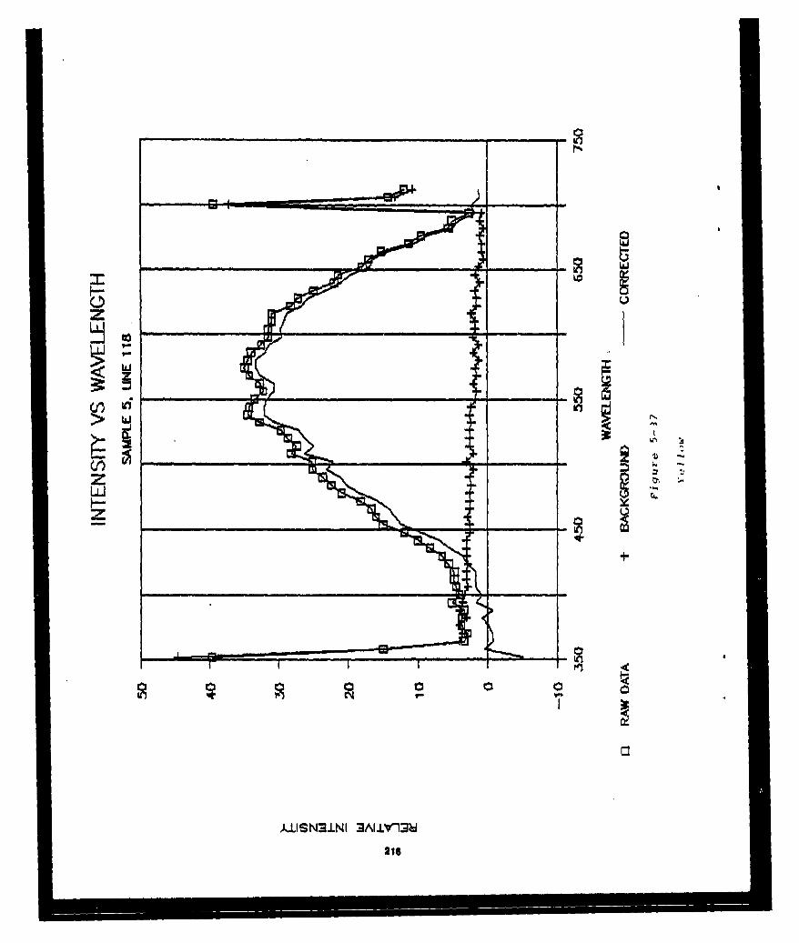
I ELL
z el
z
lz
kUISN3J.NI 3AIIL'13h
LM
216

zIU _ _
LA; -_ _
K-13 <-
z1
kUISNJ.LNI 3AI.L~Y'13
217

z
z
I- U0 '0I
31:
21 S

> LU
z 'U
kIISN9LI 3AL I I -
219
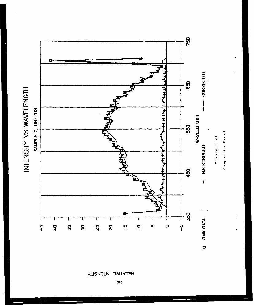
64
z E
z+
w l 0
220

Appondix A
221

ý-HEMSPEC STE looS
O AMERICAN HOLOGRAPHICCHEMSPEC 100S
CONCAVE HOLOGRAPHIC DIFFRACTION GRATINGS
This high performance, compact,rugged, spectrometer/spectrographis designed for use with a variety ofmulti-channel diode array detectors.
At last, a Versatile toolfor the Instrument Developer
The CHEMSPEC 100S is a Research
or Development instrument for the:
BID-MEDICAL INSTRUMENT DESIGNER
INDUSTRIAL CHEMIST
ELECTRO-OPTICAL ENGINEER
UNIVERSITY RESEARCHER
AMERICAN HOLOGRAPHICQUALITY 6
The CHEMSPEC 100S has the largest selectIor6 of aberratiun c;orretc!ed Holographic Diffraction_Gratings available in any commercial spectrometer, All AMERICAN HOLOGRAPHIC gratings areoriginal master quality to Insure the lowest stray light levels possible in a small instrument.
CURRENT APPLICATIONS:ABSORPTION SPECTROSCOPY CLINICAL CHEMISTRY
FLUORESCENCE EMISSION SPECTROSCOPY
COLORIMETRY HPLC DETECTIO()N222

Chmse 100 SPCROEE
FEATURES SELECTION OF YOUR
'HIGH THROUGHPUT- F12.210SC NIU A ON7STEP 1: SvI.,zt adiode array based1
*24 DIFFERENT HOLOGRAPHIC DIFFRACTION Upon the following requrements: 4 iiGRATINGS SPECTRAL RANGE
DtRmiEStepOpeLU teTION o
'CONVENIENT DETECTOR MOUNTING NUMBER OF ELEMENTSBLOCKS( FOR STANDARD 01I001 ARRPAYS COST
'CAST ALUMINUM HOUSING FOR MECHANICAL from Tables l and IVRlIGIDITY
STEP 2: Select the CHLIMEFEC 10011'INTERCHANGEABLE FIXED WIDTH ENTRANCE Gratling from Table 11 that produces the7SLITS Mnd/or FIBER OPTIC INPUT reqtuired spectrum over the length ofI
the detector array 33*EXTERNAL FOCUS AND WAVELENGTHADJUSTMENT STEP 3: Choose the optical slt that
matches the diode9 array pixel size.(Assume 1 i ratio between slt and altImage,)fa PA~$Id Spetingra", Qiaino
011ffraction GratingTable 11
Tal ~III
Deteictor Mount
Tal
TABLE I
CHEMSPEC 100S DETECTOR MOUNT SELECTION:Detector Detector Psackage si20Mount Typical Diode
qVCt29 g9 LOP911P 1-1yril Material Array (Sai Table IV)DM001 2. 00" 6J, O"Irin 35 or 31 element HamamatsuDMV002 1.60, -.1' Deiin 25.4min Self Scanning ArrayDM003 4.7 diameter iruno 1ldiiyu Ahrnintim Intnitorilfed Diode ArraysDM004 2. 1* 60"0.' rmi 35 element United Detector
DMQ99 CUSTOM plpiuiso ,p.oiiy)
See TABLE IV tor Diu~ij klaoiau.t.ursr Cios Rieference Chart

8 3S044610S8 AM HOLOGRAPHIC 05/03-96 16144 P.04
Ie
22
224
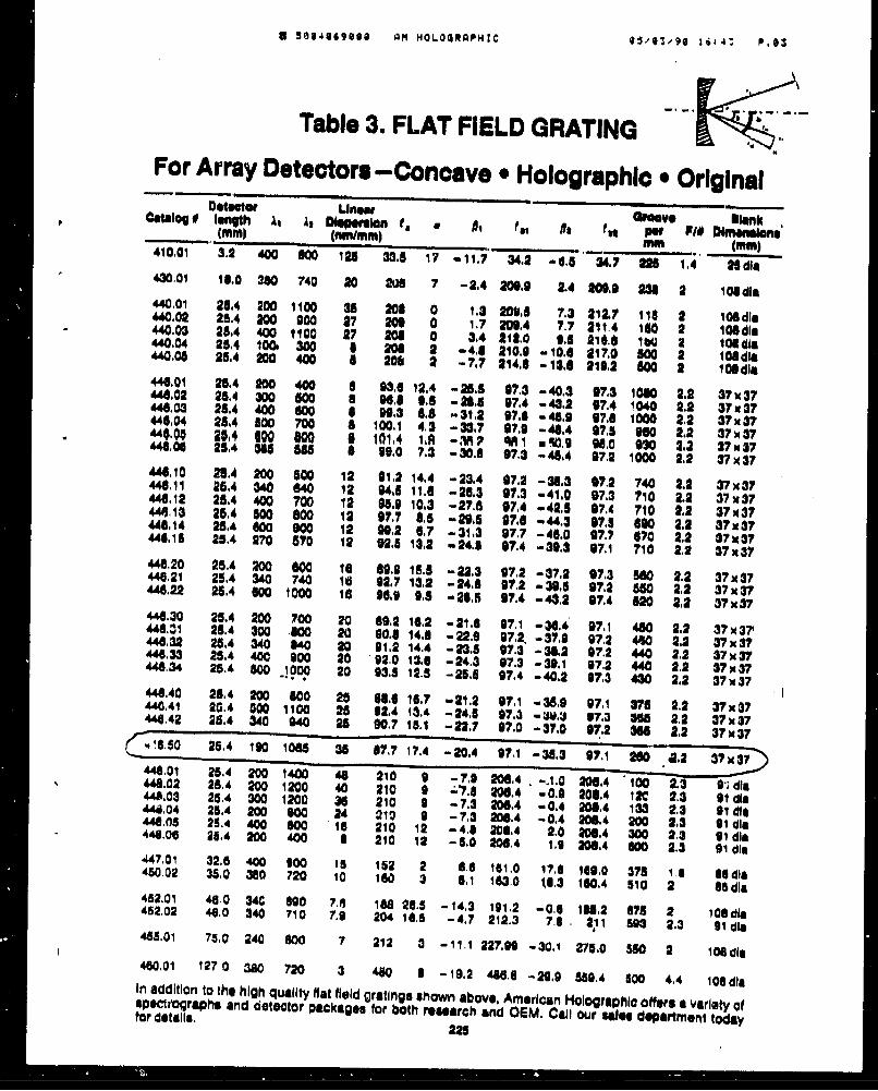
8 Su84869960 AM HOLOORAPHIC H i.a., P.*$
Table 3. FLAT FIELD GRATINGFor Array Detectors -Concave * Holographic * Original
Detbetor Unuaw Val bo "Catalog 0 length A, as Dispeislan 01 * jto t-- p- , p_. ... Ilmne ,"I" .'__ . mm *... (mM)4mm- 400 000 128 33.5 17 -11.7 34. , -0,5 34.7 226 1,4 26 die
430.01 16.0 380 740 20 206 7 -2,4 o00.0 2.4 209,1 = 2 103die440,01 25.4 200 1100 35 200 0 1.3 200.8 7.3 212.7 118 2 10Odin440.02 25.4 200 900 97 200 0 1,7 209,4 7.7 211.4 180 2 108dlm440,03 25.4 400 1100 27 206 0 3.4 212.0 0.5 216.4 160 101 ldia"440.04 25.4 1001 300 6 208 2 -48 2110.0 -10.4 217,0 I00 2 10110"440.06 28.4 200 400 A 206 4 -7.7 214.1 -13. 6 216.2 See 2 l06dla441.01 25.4 200 400 8 93.0 12,4 -26.8 07.3 -40.3 07.3 1080 2.2 37X37"44S,02 28.4 N0 600 8 96.6 6.6 -20.6 07.4 -43.2 97.4 1040 2.2 3737"44S.03 25.4 400 600 0 99.3 8.8 -31.2 97.6 -45.9 97.6 1000 2.2 37w37446.04 254 S0 700 8 100.1 4.3 -33.7 07.9 -4.4 07.5 9060 2,2 37x37"4.00 K94 100 080 101.4 IA -RP *A1 u'I 98.0 030 2.3 37 x 37"11,011 25,4 365 515 B 99,0 7.3 -30.0 97.3 -45.4 07.2 1000 2.2 37 x 37448.10 25.4 N00 500 12 21,21 14,4 -23.4 07.2 -38.3 07,2 740 2.2 37X37440111 26.4 340 640 12 94.5 11.0 -26,3 97.3 -41.0 97.3 710 2.2 37x3744. 12 25.4 400 700 12 05.0 10.3 -27.6 97.4 -42.5 07.4 710 2.2 37x37"44.13 25.4 00 800 12 97.7 8.6 -29.5 97,8 -44.3 97.5 800 2.2 X37-448.14 5,.4 6W OW0 12 20.2 6.7 -31.3 97.7 -4.0 07.7 670 2.2 37X.37"44.15 25.4 270 570 12 92.5 13,2 -24.8 .7.4 -30,3 97.1 710 2.2 37x37448.20 25.4 200 WO 10 60.9 15.8 -22.3 072 -37.2 07.3 580 2.2 37X440.,21 25.4 340 740 Id 92.7 13,2 -24.8 973 -39,6 97.2 50 2.2 37x37"448.22 25.4 400 1000 16 96.9 0.5 -28'5 97.4 -4,32 97,4 W0 2.2 37x37"440.30 25.4 200 700 20 809.2 16.2 -21.6 07.1 -36.4 07.1 480 2.2 37?37""141.31 25,4 300 6400 20 00.8 14.8 - 22.9 972.2 -37.0 97.2 440 2.2 37x3?446.32 25,4 340 840 20 01.2 14.4 -235 07.3 -31.2 07.2 440 2.2 37x37"4.33 25.4 400 900 20 92.0 13.0 -24.3 97.3 -31.1 97.2 440 2.2 3xV37448.34 25.4 500 _I.000 20 93.8 12.8 -25.8 97.4 -40.2 97.3 430 2.2 37*37446.40 26.4 200 800 25 68.0 16.7 -21.2 97,1 -35.9 97,1 371 2.2 37x37448.41 2_.4 000 1100 25 12.4 13.4 -24.5 07.3 - 41.J 97.3 368 2.2 37XV"40.42 25.4 340 00 2 90.7 15.1 -22.7 97.0 -37.0 97.2 3N 2.2 37x37.. _ 25.4 190 1065 38 87.7 17.4 -20.4 97.1 -30.3 97.1 NO .2.2 37x3l44801 25.4 200 1400 46 210 0 -7.0 206.4 , -A.0 206.4 100 2.3 C'cdls446.02 25.4 200 1200 40 210 0 -7.8 •,0. -0.0 •06.4 120 2.3 91 dli448.03 25.4 300 1200 3 , 210 9 -7.3 206.4 -0.4 208.4 133 2.3 91 die448.04 25.4 200 00 24 210 9 -7.3 206.4 -0.4 208.4 200 2.3 91 dl,448.0 29.4 400 80 16 210 12 -4.6 206,4 2.0 W1064 300 2.3 01 dil446.00 25.4 200 400 1 210 12 -5.0 2W0,4 1. 206.4 600 2.3 21 dli"47.01 32.6 400 900 15 152 2 8.6 161.0 17.8 11910 378 1.6 1ldie460.02 35.0 380 720 10 160 3 6,1 183.0 !113 110,4 510 2 85dla452.01 46.0 34C 800 7.5 18 28.5 -14,3 191.2 -0.5 1U., 878 2 108die452.02 44.0 340 710 7.9 204 16.5 -4.7 212.3 7.6 , 911 593 2.3 01 die488.01 75.0 240 600 7 212 3 -11.1 227.00 -30.1 275.0 SWC 2 106 di460.01 1270 3W0 720 3 480 I -19.2 460.6 -2.90 559.4 500 4.4 108 diaIn addition to the high quality flat field gratings shown above, American Holographic offers a variety ofspsctrographe and detector packages for both rsearch and OEM. Call our sfee department todayfor details. 226

Appendix B
226
III i I

Section 2
Camera Specifications
2.0 MC9000 Series Camera Specifications
2.1 MechanicalWeight 12 ounces (340 grams,
excluding lens, extension tubes,etc.
Dimensions See Figure 1
2.2 Optical
2.2.1 MC9128"Sensor MOS
Resolution 16,384 pixels (128 x 128)
Active Area 7.68 x 7.68 mm (.30" x 30")
Pixel Spacing 60 lnmeter (center-to-center)
Saturation Exposure 0.155 jLjoule/cm 2 (test light"source @ 28700K, typical)
2.2.2 MC91256Sensor MOS
Resolution 65,536 pixels (256 x 256)
Active Area 10.24 x 10.24 mm (.40" x .40")
Pixel Spacing 40 p.rneter (center-to-center)
Saturation Exposure 0.4 gjouie/CM2 (test light-source
@ 28700 K, typical)
2.3 Electrical
2.3.1 Power Inputs
Voltage/Current +12V:1:50 mV @300 mA-12V i100 mV @300 mA+5V ±100 mV @500 mA
Power Consumption <5 watts
227

2.3.2 MC9128 Differential Video (A) and (B) Outputs
Pixel Rate 525 KHz - 8 MHz
Frame Rate 25 - 380 frames/second
Line Flyback Period 36 clock cycles (minimum)
Frame Flyback Period 36 clock cycles (minimum)
Peak Saturated Video IV :1000 mV (into 1000 load)2V ±200 mV (open circuit)
NOTE: Refer to Section 4.3 for a description of the recommendeddifferential video line receiver and the output to be expected.
Sensor Photo Response il10% of saturated outputNonuniformityDynamic Range ;1 00:1 (defined as the ratio of
saturation voltage to p-p darkpattern, 0 50 frames persecond)
NOTE: The Dynamic Rlange specification excludes the first andlast pixel of each line and the first and last line of each frame. ,
Signal to Noise k1000:1 (defined as the ratio ofsaturation voltage to peakrandom pixel noise)
2.3.3 MC9256 Differential Video (A) and (B) Outputs
Pixel Rate 1.9 MHz- 8 MlWz
Frame Rate 25 - 105 frames/secondL
Line Flyback Period 36 clock cycles (minimum)
Frame Flyback Period 1201 clock cycles (minimum)
Peak Saturated Video 1 V ±t200 mV (Into 1 00Q~ load)2V ±400 mV (open circuit)
Sensor Photo Response ±10% of saturated outputNonuniformity
Dynamic Range k1O00:1 (defined as the ratio ofsaturation voltage to p-p dark
228

I
pattern, @ 50 frames persecond)
NOTE: The Dynamic Range specification excludes the first andlast pixel of each line and the first and last line of each frame.
Signal to Noise W1I000:1 (defined as the ratio ofsaturation voltage to peakrandom pixel noise)
2.3.4 Differential Digital Conform to EIA-RS422Signal Outputs specifications (see Section 4)
2.3.5 Differential Digital To be driven by line driversSignal Inputs meeting EIA-RS422
specifications (see Section 4)
S2.4 Environmental
Shock 20G
Vibration 3G, slnusoidal over 5 Hz to 150. Hz
Operation Temperature Range 0 to 500 celsius (measured atcamera mounting baseplate)
SStorage Temperature Range -40 to +80P celsius
I22II
llr1 . -
j l III II
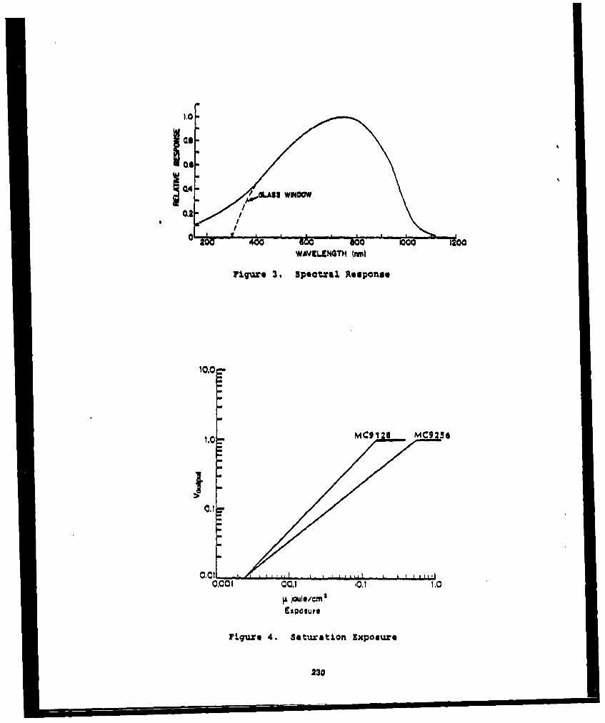
ag It- t "o o
WAVJ•NGXWT' (im)
Figure 3. Spectral Response
¶0.0 =
MC9120 MC9236
II
0.001 00.1 ,0,? 1.0
Exposure
Fiqure 4. Saturati.on Exposure
230

11
LaW
""frot Sack
1231

Appendix C
232

1.2 MVI SPECIFICATIONS
This section contains performance, physical, and environmental specifications for theMV1 board. Additionally, power requirements are provided. Refer to Chapter 3 'orinformation regarding video input. video output, frame store memory, and host accessspecificatlons.
POWER REQUIREMENTS
+ 5 Vdc 2.50 A- 5 Vdc 185.00 mA (NOTE: The PC's power supply must meet this
specification.)
SIZE
13.3 " L x 4.25" H (Occupies a full IBM PC/XT card slot.)(33.78 cm. x 10,70 cm.)
ENVIRONMENTAL
Storage Temperature: -4* to *1261 F(-200 to +700 C)
Operating Temperature: +320 to +.1220 F(00 to +500 C)
Relative Humidity: to 95%, non-condensing
1-2
233
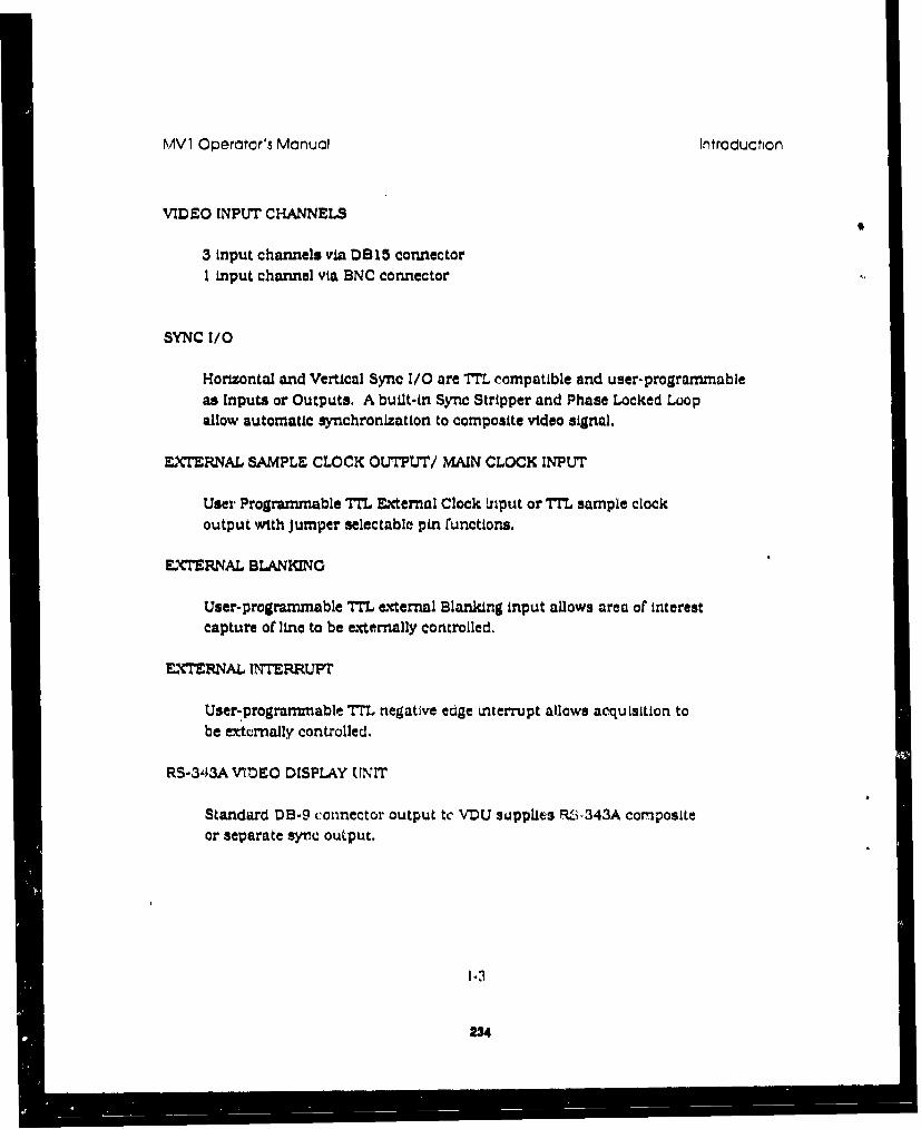
MV1 Operntor's Manual Introduction
VIDEO INPUT CHANNELS
3 input chan~nels via D815 connectorI input channel via BNC connector
SYNC I/0
Horizontal and Vertical Sync I/O are TrL compatible and user-programmableas Inputs or Outputs. A built-in Sync Stripper and Phase Locked Loopallow automatic synchronization to composite video signal.
EX'•RNAL SAMPLE CLOCK OUTPUT/ MAIN CLOCK INPUT
User Programmable TML External Clock Input or TTL sample clock
output with Jumper selectable pin runctions.
EXTERNAL BLANKING
User-programmable TTL external Blanking input allows area or interestcapture of line to be externally controlled.
EXTERNAL INTERRUPT
User-,programmnable TML negatIve edge Interrupt allows acquisition tobe excturnally controlled.
RS-343A VTnEO DISPLAY UNIT
Standard DB-9 connector output tc VDOL supplies RAi,.343A compositeor separate syrc output.
234

MV1 Operator's Mcnual Introduction
OUTPUT VIDEO DAC
Triple 8-bit high speed video DAC's produce over 16 million colors.Can also support monochrome composite display with 256 shades of grey.
VIDEO DISPLAY STANDARDS
Board can be factory-configured ror NTSC or CCIR compatible videodisplays.
VIDEO INPUT
NTSC. CCTPM RS-170, RS-330, and CCD Line/Frame cameras.
1.3 ORDERING INFORMATION
Table I -I provides the part numbers and a general description of each part associatedwith the MV1 Board, Detailed descriptions of the options and accessories are providedin Chapter 8.
Table 1- 1. MV1 Ordering frlformation
"MV1 Boardo and Intertage Box..
Pan No. Description%4V1.170 MV! Irams/Une Grabber with n3170 lnteriace.MVICCIR MV I Frome/Line mrabber with CCIR Interrace.MVIB. L Cenhric Intorfmae Box.SMV12.PS Interrace Box Power Supply.
camera.
* ~ ~ a No, ___________- DescriptionJE2362 RSI-170 CCD Camera W/ Is mm al/ ldnCT-3800 RS.lT0 CCD Camera w/ 16 m,*n a/I lenaJE2352X CCIR CCD CameraCAM-PS 12 Vda @ 300 nmu wall-mount Lxtcrnal power supply with screw teminal output
c connector. (fr omeras)
1-4
235

4MV1 Operator's Manual Theory of Operation
S211I I LUTE
IIN Ago
LUT DOIPI.AY -
ORRIN "N\To I...amass D
mu .11,A/ SWITCHINGLU
III UNETWORK BLUEPROG, DISPLAY ~ OA
GAIN ocLUT
F 25. F LUlD
TIMING
GINCNATION VIDOm 166 KITSYSTIM Q GRAPHICS
CONTROCLLER14 oo 0 GIMRAPI
B 60 ~ IMAGE MEMORY
7 ý7 PC @US INTERFACE
Figure 2- 1. Functional Block Dia gram
2-2
230

MV1 Operator's Manual Operating Specifications
CHAPTER 3OPERA TING SPECIFICATIONS
3.1 GENERAL
This chapter details operating specifications for the MV1 Board. Specifications ror
standard video input types, video output signals. and timing specifications are given.
All specifications are typical at +250C and rated voltage unless otherwise specified.
3.2 STANDARD VIDEO INPUT
Analog Input 4 channel interlaced, non-interlaced, or line scan. A
jumper.selectable low-pass filter is available to atten-
uate unwanted high frequency information from
NTSC and PAL signals.
MV -170 RS-170, RS-330, NTSC; ac-coupled: programmable
channel, D.C. offset, D.C, restoraUon, gain
NtVI-CCIR CCMRPAL-: ac-coupled: programmable channel, DC.
offset, D.C. restoration, gain
Number of Inputs 4
SynchronizatLon
External From video source via on-board sync stripper or Sync
1/0 pins.
Internal From on-board VSC or 'TV Gen. with jum-er se-
lectablc TTL Sync outputs VRES or VSYNC and
CSYNC or HSYNC,
22i7
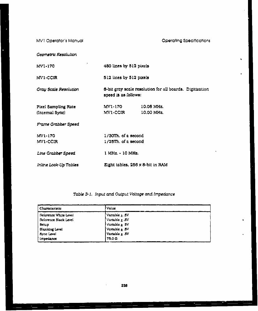
MV I Operator's Manual Operating Specifications
Geometric Kesolutton.
MVI-170 480 lines by 5 12 pL'cels
MV1-CCIR 5 12 Unes by 5 12 pLucels
Cray Scale Resolution $-bit gray scale resolution for aU boards, Digitizationspeed is as follows:
Pixel Sampipng Rate MV1 -170 10.08 MHz.(Internal Sync) MWl-CCIR 10.00 MHz.
Fram~e Crabber Speed
MV1- 170 1/30Th. of a secondNIVI-CCIR 1/25Th. of a second
Line Crabber Speed 1 MHz. - 10 MHz.
INine Look- Up Tables Eight tables, 256 x 8-bit in RAM
Table 3- 1. Input and Output Voltage and Impedance
Ch-meteriatc Value
iRcrcrence White Level Vattable I. 5VRefcrence Black Level Variablct.SVSetup Vaxriable j SVBlanking Le-vel Variablet± ,VSync Level Variable t MVImpedance 715.0 fl
238

MVI Operator's Manual Operating Spec.1fications
3,t.0 ' IIDEO OUTPUT
Output Sfnal Interlaced. ROB, or monochromeEmbedded Composite Sync in Green(Separate Composite Sync also available)
ZMV1-170 RS-343A, RS-170, dc-coupled
MVI-CCIR RS-343A. CCIR, dc-coupled
D/A 3
Resolution 8-bit
ROB Output 16 million colors
Monochrome Output 256 grey levels
Display Look-Up Tables Eight 256 x 24-bit RAM
Sync Signal Output RS- 170 and CCIR defined signals:Composite sync on green or separate
Aspect Ratio 4:3
Overlay Modes 7 user-programmable overlay modes
239

MV1 Operator's Manual Operating Specifications
3.4 FRAME STORAGE MEMORY
Number 2
SizeEach 512 x 512 x 8-bit. 256 Kbytes
Total 512 Kbvtes
Bank.* can be arranged as 512 x 512 or 1024 x 256and any size range within these outer limits,
Access Transparent from bus; read or write any time:bit-plane mask available
3.5 RS- 170 AND CCIR TIAIING
Table 3-2. Horizontal Ttming"
"Characteristic MVI.170 MVI.CCIRI[or1i Frequency 15,570 Hs. 15,825 Hz.Horis Period 63.40 •a 84.00 pHorlz Actuve Scan 52.28 i.Ls I2.17 paHoriz Blanking 21,23 I I 1.82 pKaort Sync 4.1,200 4.687 • . .Scan Clock 10 MHZ. 10 MHz.Pixel Rate 100 fl. 100 na.Pixel Aspect Ratio ,4/3 4/3Norral Tirmnp. All are programmable lor non-standard ucquisLion arnd dispay.
240

Robot Companies
2
,241

ABB Robotics 16250 West Glendale DriveNew Berlin, "rI 53151-2840
Jack Dreyer (414)785-3400
AEG PO Box 160Pittsburgh, PA 16230
Advanced Mmnu&chuig Systems 6075 The Corners ParkwayNorcrou, GA 48120(404)448-6700
Cybermotion 5457 Aerospace RoadRoanoke, VA 24014
Robert J. Breen (703)982-2641
Clmcorp 899 West Highway 96Shoreview, MN 55126(612)484-7261
Cincinnati Mllacron 795 West AlexanderPO Box 1327Greenwood, SC 29648
Clay-Mill Technical Systems 2855 Deziel DriveWindsor, Ontario N8W 5A5
Dave Thorn (519) 944-7902
General Atomics 10955 John Hopkins DrivePO Box 85608San Diego, CA 92138-5608
GMF Robotics Box 811Bloomfield Hills, MI 483031-800-231-4112
GRACO Robotics 12898 Westmore AvenueLivonia, ?I 48150(313)523-6300
Miller Electric Appleton, WI 54914
242

NIKo Robotic Group 21277 Bridge StreetSouthfleld, MI 48034
Dean Roberson (313)352-4510
Thermwood PO Box 436Dale, IN 47523
Mark Drone (812)037-4476
SPAR Aerospa 1700 Ormont DriveWeston, Ontario M9L ZW7(416)745-9630
TOKICO 1203 Commerce Drive SouthDearborn, MI 48120(313)33.-•280
US Air Force Sacramento Air Logistics CenterMcClellan Air Force Base, CA 959652
Ogden Air Logistics CenterHill Air Force Base, UT 84056-5990
Yakawa 3160 MacArthur Blvd.Northbrook, IL 60062(312)291-2340
'43
I' • i. .. " ' "

Sensor Companies
244
ACE
ADE 77 Rowe StreetNewton, MA 02166(617) 969-000
Aemotech 8804 Lome CourtRaleigh, NC 27615
Charles E. ZeUman (919) 848-1965
Agastat
AllenuBradley
Alpha
Aromat 629 Central AvenueNew Providence, NJ 07974
Brett Hammerschmidt (201) 464-3850
Automatix
Banner
Baumer 122 Spring Street, C-6Southington, CT 06489
Robert Frais (203) 621-2121
CCDI
Chesapeake Laser System 4473 Forbes BoulevardLanham, MI) 20706
J. Bradford Merry (301)459-7977
Cleveland Machine Controls, Inc. 7550 Hub ParkwayCleveland, OH 44125
Donald Tomko (216)524-8800
Computer Reoguition Systems
248

Contaq 15 Main StreetBristol, VT 05443(802) 453-3332
Crystal Technology
Custom Machine
CyberOptics 2331 University Avenue SEMinneapolis, Minnesota 55414
Michael Riddle (612) 331-5702
Diffraoto 2835 Now DriveWindsor, Ontario NST 3B7
Steve Dawson (519) 945-6373
Dolan Jemiar
Ealingf
Efector
Electro Corporation
Elec atic
HOTec
Flow Research
General Scanning, Incorporated 800 Arsenal StreetPO Box 307Watertown, MA 02272(617) 924-1010
Huntleigh Technology
Kaman
Keyence 17-17 Route 208 North
246

Fair Lawn, NJ 07410Fred G. Poelzing (201) 791-8811
Laser Design Incorporated 8316 Pillsbury Avenue SouthMinneapolis, MN 56420
C. Martin Schuster (61.2) 88449648
Lion Precison 7685 Washington Avenue SouthMinneapolis, MN 56435-2705
Robin Wilcox (012)944-1830
Magnaflux
Mama Products 280 Lincoln StreetHngham, M0IA 02043-1796(617) 749-4800
MiroSwitch 1190 W. Druid Hills DriveSuite 218Atlanta, GA 30329(404) 248-2565
MS Systems Corporation
NDC Systems
NDT Instruments
Ohmart 4241 Allendorf DriveCincinnati, OH 45209(513) 272-0131
Oldelft
Omron
Pepperd and Fuchs
Perceptron
247
Photo Acoustic Technology
Photo Reearch
Polaroid Ultrasonic
Qualcorp Shelter Rock RoadDanbury, Cr 06810(800) 367-045
Quantm Meaurment. Corporation Suite 2501270 Winchester ParkwaySmyma, GA 30080
David Robinson (404) 433-0093
Quester
P weniaw
RVSI 425 Rabro Drive EastHappauge, NY 11788
Paul Otto (516)273-9700
Scientifc Technology Incorporated
Selcom PO Box 250Valdese, NC 28690(704) 874-4102
Sensotec
Sick 7694 Golden Triangle DrivePO Box 444-240Eden Prairie, MN 55344(612)941-6780
Silicon Graphics
Simmonds Precision
248

Spectron
Spectronics 9655 SW Sunshine Court #500Beaverton, Oregon 97005
Dennis G. Ortega (503) 643-8030
Spindler and Hoyer
Staveley
S~Tritron/i
Turck
Ultrasonic Arrays 18612 142nd Avenue NEWoodinville, WA 98072
Kerr Sheeks (206) 481-6611
United Microwave Products Jnc- 22129 S. Vermont Ave.Torrance, CA 90502(213) 320-1244
Vanzetti Systems 111 Island StreetStoughton, MA 02072
Richard L Alper (617) 828-4650
Wagner Instruments
Weidmunler 535 Tollgate RoadElgin, IL 60123
Ernest J. Foldvari (708) 742-0122
Wyco
Zygo Laurel Brook RoadMiddlefield, CT 06455-0448
249

Laser Companies
250

Acme.Clev)annd Syftems Division 1600 Enterprise ParkwayTwinsburg, OH 44087-2202
ACRO Automation Systems, Inc. 2900 West Green Tree RoadMilwaukee, WI 53209
Amada Laser Systems 7025 Firestone Blvd.Buena Park, CA 90621(714)670-1439
BatelleWCoumbus Division 505 King AvenueColumbus, OH 43201
Gordon Zeidmann (614)424-7405
Coherent General, Inc P.O0. Box 1027Tryon, NC 28782
Bob Reynolds (803)582-1872
COMAU Robotics 466 Stephenson HighwayTroy, MI 48083-1195
Control Laser Corporation 7503-T Chancellor Drive
Orlando, FL 32809Al Pearson
Ferranti International 4915 West 67th StreetChicago, IL 60638-6493
Michael F. Holmes (708) 564-3800
Hughes Aircraft Company 6155 El Camino RealCarlsbad, CA 92037
International Laser Machines Corp. 1806 Stout Field West Drive
Indianapo's, IN 46241
International Technical Associates 2281 Calls de Luna
Santa Clarm, CA 95054Dr. Paul Lovoi (408)748-9955
Laser Machining, Inc. 500 Laser Drive
251

Somerset, Wisconsin 54025Dave Plourde (715)247-3285
Laser Mechanisms, Inc. PO Box 2064Southfield, MI 48037
Meier Griesheim Steigerwald StrahltechnikBenzsrtaBe 11, Postfach 1365D-8093 Puchheim, West Germany
LASAG Corporation 702 West Algonquin RoadArlington Heights, IL 60005
Art Spera (312) 593-3021
Laakman Electro-Optics, Lmm 33051 Calle AviadorSan Juan Capistrano, CA 92675
Laser Systemee 3 rue Denis PapinBeauchamp 95250, France
Lumonics Laser Systems Group 4504 Graham RoadGreensboro, NC 27410
Jeffrey C. Jones (919)854-9679
Plasmatronic, Inc. 2460 Alamo, S.E. Suite 101Albuquerque, New Mexico 87106
Kim S. Crissman (505)343-9430
PRC Corporation North Frontage RoadLanding, NJ 070850
Precision Technologies, Inc. 120 Post RoadEnfield, CT 60682-5699
Heike Rukas (203)741-2281
Spectra-Physics, Inc. 3333 North First StreetSan Jose, Ca 95134
US Air Force Warner Robins Air Force Base, GA 31091
252

Tug Companies
253

FMC
Jetway Systems 1805 West 2550 SouthPO Box 9368Ogden, UIT 84409-0368
Tug
, U.S. Governmient Prinling Office: 992-6848-127/62267 254