automated gap filler device - welcome to the clean sky website
TRANSCRIPT

Automated Gap Filler Device JTI-CS-2012-01-SFWA-02-020
January 2011
Presented by
Jeremy Bradley – Airbus, Materials & Processes Engineer
CFP Information Day

© AIRBUS Operations LTD. All rights reserved. Confidential and proprietary document.
Background
• Natural Laminar flow (NLF) has been identified as a key
technology to contribute to the reduction of emissions for future
short range aircraft.
• Studies have been launched within SFWA to investigate the
feasibility of producing such a design. The work will include ground
based and flying demonstrators.
• One potential concept includes a joint between the main wing box
and leading edge structure.
This joint must be filled to the specified
surface finish requirements to maintain
NLF.
Page 2
January 2011

© AIRBUS Operations LTD. All rights reserved. Confidential and proprietary document.
Main Objective
‘To develop an automated device that
is capable of filling panel gaps to the
required tolerance in a high rate
production environment.’
Page 3
January 2011

© AIRBUS Operations LTD. All rights reserved. Confidential and proprietary document.
Main Objective
Page 4
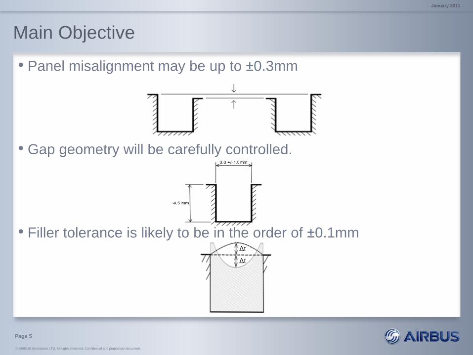
• The joggle joint shown below will include a gap between the
panels to allow application of a filler material. The gap dimensions
are of the order of 3mm wide by 4.5mm deep.
• The surface finish requirements will include:
• Misalignment tolerance on the panels to be joined.
• Variation caused by sealant expansion or contraction.
• Isolated roughness requirements on the filler surface.
(Full details of the surface finish will be made to successful applicants)
January 2011
© AIRBUS Operations LTD. All rights reserved. Confidential and proprietary document.
Main Objective
• Panel misalignment may be up to ±0.3mm
• Gap geometry will be carefully controlled.
• Filler tolerance is likely to be in the order of ±0.1mm
Page 5
Δt
Δt
January 2011

© AIRBUS Operations LTD. All rights reserved. Confidential and proprietary document.
Main Objective
• The total length of the joint to be filled will be between 4 and 15
metres and may go across chord wise joints.
• This means that the minimum uninterrupted length to be filled is
approximately 4 metres.
• To achieve rate, this process should be able to fill a 30 metre
length in less than 3 hours.
Page 6
January 2011

© AIRBUS Operations LTD. All rights reserved. Confidential and proprietary document.
Main Objective
• As shown on the A320 wing below, a typical span wise joint
exhibits some double curvature.
• A suitable filler device should be able to operate in a fully 3D
environment.
• Surfaces either side of the joint may be painted or unpainted and
may be dissimilar.
• It would be beneficial but not essential for the device to be able to
fill chord wise joints, countersinks and minor in service defects.
Page 7
Filler Line
January 2011
© AIRBUS Operations LTD. All rights reserved. Confidential and proprietary document.
Materials Information
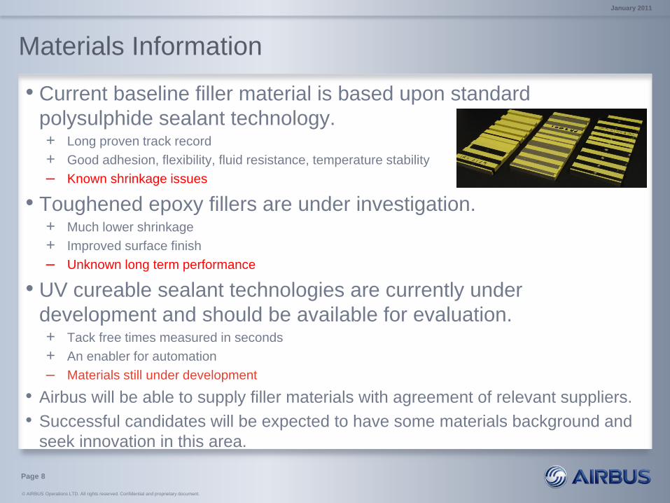
• Current baseline filler material is based upon standard
polysulphide sealant technology. + Long proven track record
+ Good adhesion, flexibility, fluid resistance, temperature stability
– Known shrinkage issues
• Toughened epoxy fillers are under investigation. + Much lower shrinkage
+ Improved surface finish
– Unknown long term performance
• UV cureable sealant technologies are currently under
development and should be available for evaluation. + Tack free times measured in seconds
+ An enabler for automation
– Materials still under development
• Airbus will be able to supply filler materials with agreement of relevant suppliers.
• Successful candidates will be expected to have some materials background and
seek innovation in this area.
Page 8
January 2011

© AIRBUS Operations LTD. All rights reserved. Confidential and proprietary document.
Work Programme
• The successful applicant shall develop a prototype device capable
of filling the panel gap on the ground based demonstrator (See
original topic description).
• The work programme is constrained to 12 calendar months.
• The body of work shall include:
• A background study on filling techniques and devices
• Benchtop prototype development
• A method of evaluating the performance of the device,
including test coupon production.
• Technical drawings of the device
• Submission of a final prototype for further evaluation
• A detailed final technical report
Page 9
Mid-Term
End of Project
January 2011

© AIRBUS Operations LTD. All rights reserved. Confidential and proprietary document.
Scope for innovation
•Degree of automation
•Novel Materials (Photosensitive, thixotropy)
•Multiple operations (single or multi-pass)
–Gap analysis
– Secondary finishing
– Post application metrology
•???
Page 10
January 2011

© AIRBUS Operations LTD. All rights reserved. Confidential and proprietary document.
Any Questions?
Page 11
January 2011

© AIRBUS Operations LTD. All rights reserved. Confidential and proprietary document.
© AIRBUS Operations LTD. All rights reserved. Confidential and proprietary document. This document and all information contained herein is the sole property of AIRBUS Operations LTD. No intellectual property
rights are granted by the delivery of this document or the disclosure of its content. This document shall not be reproduced or disclosed to a third party without the express written consent of AIRBUS Operations LTD. This
document and its content shall not be used for any purpose other than that for which it is supplied. The statements made herein do not constitute an offer. They are based on the mentioned assumptions and are expressed
in good faith. Where the supporting grounds for these statements are not shown, AIRBUS Operations LTD. will be pleased to explain the basis thereof.
AIRBUS, its logo, A300, A310, A318, A319, A320, A321, A330, A340, A350, A380, A400M are registered trademarks.
Page 12
January 2011