automated fluid perfusion system for a tissue …web.cecs.pdx.edu/~far/me493/examples of old final...
TRANSCRIPT

Automated Fluid Perfusion System
for a Tissue Synthesis Bioreactor
ME493 Final Report - Year 2010
Team Members
Darius Respini-Irwin
Jordan Barnett
Shady Adib
Hideaki Inoue
PSU Faculty Advisor
Dr. Faryar Etesami
Project Sponsors
Dr. Sean Kohles
PSU Reparative Bioengineering Lab

2
Executive Summary
Millions of people suffer from some type of tissue loss, damage, or bone defect every
year. Tissue engineering provides a medical solution to these problems by the development of
substitutes that restore and maintain tissue functions. A bioreactor device is specifically designed
to stimulate tissue growth using synthetic scaffolds seeded with cells and supplied with a
nutritive fluid or gel. The nutritive fluid in the PSU bioreactor system needs to be replaced
periodically in order to supply the cells with fresh nutrients and remove waste products.
The Bioreactor Capstone team mission was to design, prototype and install a device that
transports a nutrient gel into small square test cells. The proposed device should fit inside an
incubator with the bioreactor system and it is automatic, environmentally resistant, and easy to
install.
The design selected to be produced was a dovetail system. This design utilizes a tool less
mounting system. This was selected due to the design’s advantage in ease of manufacture,
flexibility in sample type and shape, quick setup and repair, and ease of access to the side panel.
The designed system was manufactured in the PSU workshop. The implemented system
was then assembled and tested for leakage, flow characteristics and overall performance to make
sure it complies with the PDS requirements dictated by the customer.
A demonstration of the system in operation was attended by the customer for validation
of the main requirements. The customer was satisfied with the performance of the fluid perfusion
system developed by the Bioreactor capstone team.

3
Contents
Executive Summary ................................................................................................................. 2
Introduction and Background .................................................................................................. 4
Mission Statement ................................................................................................................... 5
Product Design Specifications ................................................................................................. 5
Top Level Design Decisions .................................................................................................... 7
Final Design ........................................................................................................................... 10
Evaluation and Verification ................................................................................................... 14
Conclusion ............................................................................................................................. 15
Appendix A - Analysis ........................................................................................................... 16
Appendix B – Part Drawings ................................................................................................. 23
Appendix C – Bill of Materials ............................................................................................. 30
Appendix D – PDS Summary ................................................................................................ 31
Appendix E – Concept Generation and Selection ................................................................. 33
Appendix F - Bibliography .................................................................................................... 38
4
Introduction and Background
Millions of people suffer some type of tissue loss, damage, or bone defect every year.
Medical treatments for such conditions include autografts (a tissue graft obtained from one part
of the patient’s body for use on another part), allografts (a tissue graft from a donor genetically
unrelated to the recipient), and metallic implants. These methods suffer from limited availability,
reliance on a limited number of volunteer donors, and there are issues of potential immune
system reaction from allografts and metallic implants resulting in rejection of the graft. For that
reason, many patients are still suffering from tissue loss or bone defects.
However, the science of tissue engineering provides medical solutions to these problems by
the development of substitutes that restore and maintain tissue functions. An in vitro (outside of
the body) tissue-engineered bone for subsequent implantation in vivo (inside of the body) is
being developed as one of these solutions. In particular, an in vitro engineered cartilage
replacement is being pursued as a way to repair injuries and damage to cartilage,
Bioreactor devices are designed specifically to support such tissue engineering applications.
A typical Bioreactor system will hold test samples consisting of synthetic scaffolds seeded with
cells which form the base of the final engineered-tissue. These scaffolds are then supplied with a
nutritive fluid or gel consisting of cells, biomaterials, and growth stimulants. Tissue growth is
then encouraged by stimulating the cells. This can be done via several methods, including fluid
proliferation through the scaffolds, and mechanical loading stimulation. The full device is placed
in an incubator that maintains the temperature, gas percentages, and humidity at certain levels to
simulate the environment inside of the human body.
The nutritive fluid in the bioreactor system needs to be replaced periodically in order to
supply the cells with fresh nutrients, to remove waste products, and to allow effective scaffold
proliferation. However, the current bioreactor system in development by the Portland State

5
University (PSU) bioengineering department research team does not have a perfusion system and
the fluid replacement is done manually. The manual process involves opening the incubator and
changing the fluid by hand. This disrupts the equilibrium within the incubator, which slows down
tissue growth. Therefore, the capstone team was asked to design and fabricate a fluid perfusion
system to be installed to the current bio reactor system to allow automated fluid replacement.
Mission Statement
The Bioreactor Capstone team will design, prototype and install a device that will
transport a nutrient gel into small square test cells. The device will fit inside an incubator with
bioreactor and not interfere with the other testing devices that monitor the cells. In addition the
system will be automatic, pressure resistant, and easy to install. The project will be documented
extensively with reports, visual aids, and presentations. A working prototype is to be installed by
the end of June.
Product Design Specifications
Dr. Sean S. Kohles and the PSU Reparative Bioengineering lab are the main costumers
for the bioreactor fluid perfusion system. The system is to be installed in the current bioreactor
device to allow automated fluid replacement. After working with Dr. Kohles and the
Bioengineering Lab team, the team developed the following major design specifications:
A. The assembly must survive the incubator environment.
The system must be able to withstand the inside temperature of the incubator which
can reach up to 50 oC along with specific ranges of CO2, O2, and humidity for extended

6
periods of time (up to 7 days). CO2 percentage ranges between 0.2 – 20 %, O2 percentage
ranges between 5 – 20 %, and the humidity percentage reaches up to 95 % RH`.
B. Time needed to replace any failed component.
During the replacement of any failed component, the open incubator time must not
exceed 15 minutes
C. Unattended Runtime
The fluid system is required to run for up to 7 days without direct supervision.
D. Time needed to disassemble, clean, and reassemble.
The process of taking apart the system for cleaning and reassembly must not take
more than 180 minutes.
E. Perfusion system physical specifications.
The system to be installed must interface with the current bioreactor system and at
the same time fit inside the incubator. The inside dimensions (in mm) of the incubator are
520(W) x 426(L) x 690(H).
F. Flow Rate.
The nutritive fluid must be supplied to the test samples at a minimum flow rate of 4
mL/min.
G. Cost:
All purchased parts and materials, fabrication, prototyping and testing processes are
funded with a 1000 USD budget provided by the customer.
7
Top Level Design Decisions
Cantilevered Sleeve:
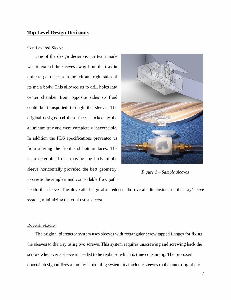
One of the design decisions our team made
was to extend the sleeves away from the tray in
order to gain access to the left and right sides of
its main body. This allowed us to drill holes into
center chamber from opposite sides so fluid
could be transported through the sleeve. The
original designs had these faces blocked by the
aluminum tray and were completely inaccessible.
In addition the PDS specifications prevented us
from altering the front and bottom faces. The
team determined that moving the body of the
sleeve horizontally provided the best geometry
to create the simplest and controllable flow path
inside the sleeve. The dovetail design also reduced the overall dimensions of the tray/sleeve
system, minimizing material use and cost.
Dovetail Fixture:
The original bioreactor system uses sleeves with rectangular screw tapped flanges for fixing
the sleeves to the tray using two screws. This system requires unscrewing and screwing back the
screws whenever a sleeve is needed to be replaced which is time consuming. The proposed
dovetail design utilizes a tool less mounting system to attach the sleeves to the outer ring of the
Figure 1 – Sample sleeves

8
sample tray. Five dovetail slots are cut into the carrying tray, and each individual sleeve has a
dovetail shaped protrusion that allows the sleeve to slide into a slot with a tight fit. Highlights of
this design include quick and simple installation and maintenance due to its tool less nature,
simple machining requirements to produce the
parts, and a reduction in material consumption
due the reduced tray size. The Dovetail fixture
also allows the applied load produced by the
pistons to be distributed on the lateral surface of
the dovetail which decreases stresses in the
sleeves.
Fluid Recirculation shape:
The team initially looked cutting a square sample chamber into the carrier sleeve for the
sake of simplicity. Examination of the design
revealed a concerning level of fluid recirculation
in the corners of the cubic sleeve. Due to the
need to flush biological contaminants and waste
products, this was considered unacceptable. The
team utilized computational fluid dynamic
models of the system to optimize the flow
design. The selected design utilized rounded corners, and an indentation on the side of the
chamber to create a uniform flow throughout the chamber, over the sample cube to minimize
recirculation.
Figure 2 – Dovetail Detail
Figure 3 – Sample Chamber Detail

9
Materials:
Materials for the bioreactor device must withstand the incubator environment without
corrosion or contamination of the nutrient fluid.
Tray – Aluminum; Aluminum is
relatively light and easy to manufacture
compared with other materials. The whole
assembly must be placed inside the incubator
at 50°C. At this temperature the properties of
aluminum won’t be changed (Mangonon,
1999), so Aluminum is safe to use in the
incubator with any adverse affect. 20~200N
of loads are applied to each sleeve, but this loads are too low to result in deformation. Stainless
steel can be used as an alternative material for the tray. Stainless steel has a strong resistant to
corrosion and rust so it is suitable material. However, it is harder material than aluminum, so it is
more difficult to manufacture it.
Sleeves – Acrylic; Acrylic is transparent material, so it does not disturb observation of tissue
growth by ultrasound transducer and digital microscope that is part of customer’s requirements.
The sleeves are inserted in the aluminum tray, so they also have to be available to be used at the
incubator temperature, 50℃. It is safe to be used up to 200℉ (93.3℃), so incubator temperature
won’t affect the sleeves. (Mangonon, 1999) Loads are applied to the sleeves, but the analysis
proves that acrylic can be used safely (Appendix A).
Figure 4-Materials used to create prototype
10
Final Design
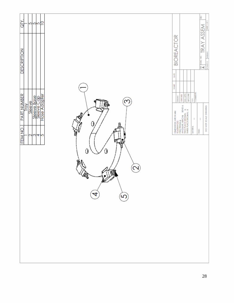
Tray:
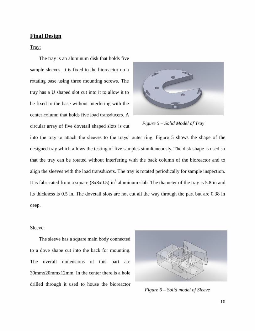
The tray is an aluminum disk that holds five
sample sleeves. It is fixed to the bioreactor on a
rotating base using three mounting screws. The
tray has a U shaped slot cut into it to allow it to
be fixed to the base without interfering with the
center column that holds five load transducers. A
circular array of five dovetail shaped slots is cut
into the tray to attach the sleeves to the trays’ outer ring. Figure 5 shows the shape of the
designed tray which allows the testing of five samples simultaneously. The disk shape is used so
that the tray can be rotated without interfering with the back column of the bioreactor and to
align the sleeves with the load transducers. The tray is rotated periodically for sample inspection.
It is fabricated from a square (8x8x0.5) in3 aluminum slab. The diameter of the tray is 5.8 in and
its thickness is 0.5 in. The dovetail slots are not cut all the way through the part but are 0.38 in
deep.
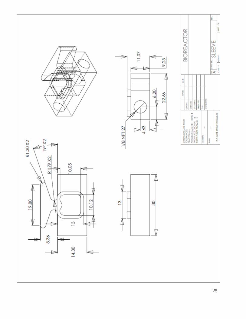
Sleeve:
The sleeve has a square main body connected
to a dove shape cut into the back for mounting.
The overall dimensions of this part are
30mmx20mmx12mm. In the center there is a hole
drilled through it used to house the bioreactor
Figure 5 – Solid Model of Tray
Figure 6 – Solid model of Sleeve

11
cartilage samples. The curvature of this hole in the center was designed to reduce recirculation
and help direct steady flow for a 5x5x5mm samples. There are two access ports that are used
connect the chamber to a reservoir and transport the fluid through the sleeve and out to waste
receptacles. On the top is an extruded rectangular shape that will fit into the sleeve cap. The
bottom will be glued sleeve base which with provide the sample holder and rest gently on the
surface of the bioreactor platform. Lastly the dovetail backside fits snuggly with the tray so that
no hand tools are necessary to secure this component of the fluid perfusion system
Sleeve Base:
Sleeve Base is made from acrylic, and its shape is
square which dimension is 13 mm×14.5 mm. The thickness
is 4 mm. This thickness corresponds to the tray thickness,
so when the sleeve is inserted to the tray, the bottom of
sleeve is aligned to the bottom of the tray.
There is a void, which is 5 mm×5 mm, on the base.
This is for the scaffold. The scaffold is stuck against the
wall and the material of sleeve is acrylic that is transparent, so a digital microscope and an
ultrasound transducer can observe the growth of tissue from the side and the bottom of sleeve
respectively.
Sleeve Cap:
Sleeve Cap is also made from acrylic. It is also square shape and its size is 16 mm ×16 mm.
This sleeve cap fits over the top of the body sleeve. This cap is for preventing the nutrient fluid
Figure 7- Solid Model of Base

12
from spilling out of the inner chamber. A hole will be cut
in this sleeve cap, and a force applicator goes through it
and applies force to a scaffold. The cap is water sealed
with and adhesive putty in order for the part to be
removed during installation and disassembly.
Fluid Input: (Reservoir, Pump, Manifold)
Fluid input is handled by means of a peristaltic pump and a large beaker. A peristaltic pump
was selected to maintain sterility of the solution. The pump draws the solution from the reservoir
beaker, and pushes it to the manifold. The manifold then distributes the solution to each of the
five sleeves. The pump is powered by an ATX 12 volt power supply.
Figure 8 – Cap Model
Figure 10 – Peristaltic Pump Figure 9 – Distribution Mainfold

13
Fluid Output: (Waste Containers)
For prototype demonstration purposes, the used fluid flows out of each sample sleeve
through a medical tube and is directed into a graduated beaker to monitor the flow rate through
each sleeve and to make sure all sleeves are equally supplied with fluid. The final product can
maintain this setup, or allow for a single outflow tank that holds all used fluid flowing out of the
five sleeves, depending on the needs of the current experiment.
Microcontroller Pump Control:
To meet the requirements for variable flow control, a custom digital pump controller was
developed. This system uses an ATMega168 microprocessor with a DS1307+ real time clock.
This allows runtime and interval to be set from zero to 1 year duration. The microprocessor uses
pulse width modulation to control the speed of the pump, allowing adjustment from zero to 80
mL/min for each sleeve.
Figure 11- Controller, first light
Figure 112-Prototyping the controller

14
Evaluation and Verification
Once the complete prototype was assembled, the various design requirements were
measured to ensure compliance with the PDS (see Appendix D)
Specification Target Metric Verification Evaluation
Flow rate 4 mL/min Prototype 0 to 80 mL/min
Unattended Run Time 7 Days Prototype 0-1 year
Adjustable Run Interval 0-72 Hours Design 0-1 year
Temp Tolerance 50 °C Design 80°C (tubing)
CO2 Tolerance 0.2-20 % Design Materials Stable in
these gasses
Al, Brass, Acrylic
O2 tolerance 5-20 % Design
People Needed to Install 1 Prototype 1
Time to Replace Failed
Component <15 Minutes Prototype <10 (estimated)1
1
Physical Dimensions mm 520x426x690 Design
Complete Maintenance Time min <180 Prototype <60 (estimated)1
1
Cost 1000 USD$ Prototype <$200
[1]The bioreactor apparatus that the team’s project will interface with is not yet complete. As
a result complete assembly/disassembly testing of the system cannot yet be performed. Estimates
based on testing performed ex-situ show the targets should easily be met.
15
Conclusion
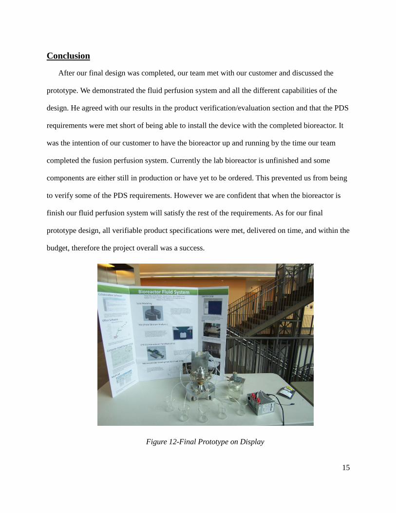
After our final design was completed, our team met with our customer and discussed the
prototype. We demonstrated the fluid perfusion system and all the different capabilities of the
design. He agreed with our results in the product verification/evaluation section and that the PDS
requirements were met short of being able to install the device with the completed bioreactor. It
was the intention of our customer to have the bioreactor up and running by the time our team
completed the fusion perfusion system. Currently the lab bioreactor is unfinished and some
components are either still in production or have yet to be ordered. This prevented us from being
to verify some of the PDS requirements. However we are confident that when the bioreactor is
finish our fluid perfusion system will satisfy the rest of the requirements. As for our final
prototype design, all verifiable product specifications were met, delivered on time, and within the
budget, therefore the project overall was a success.
Figure 12-Final Prototype on Display

16
Appendix A - Analysis
17
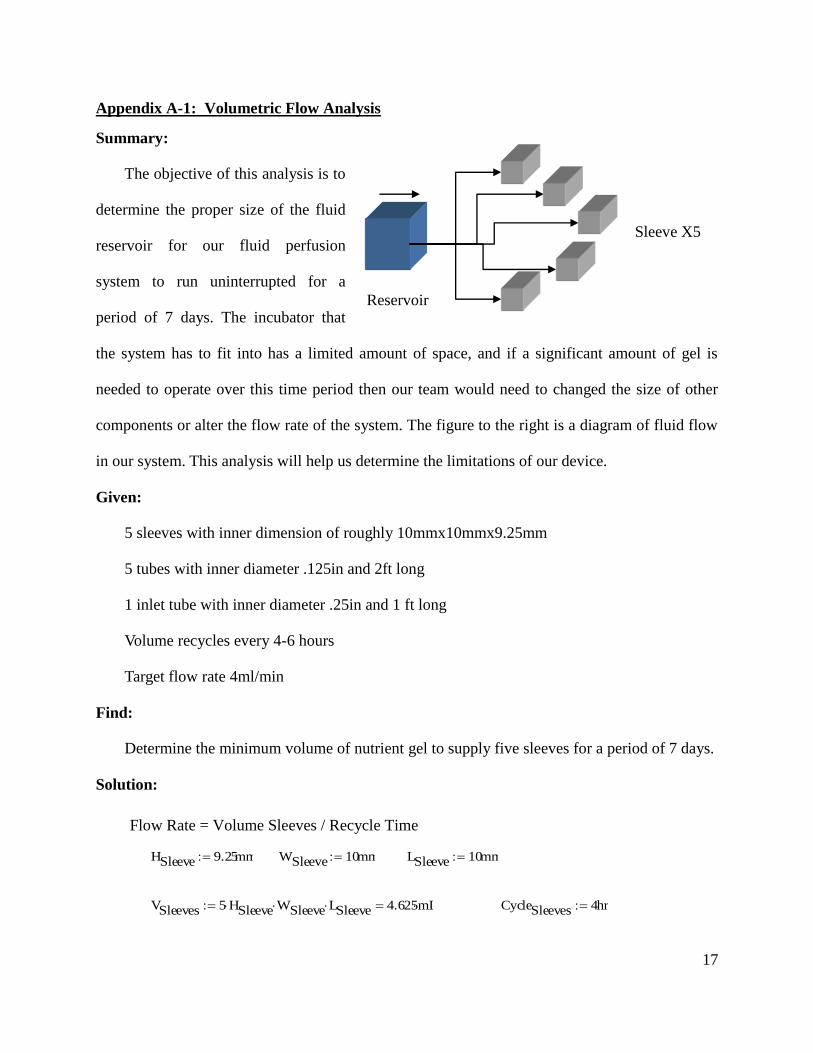
Appendix A-1: Volumetric Flow Analysis
Summary:
The objective of this analysis is to
determine the proper size of the fluid
reservoir for our fluid perfusion
system to run uninterrupted for a
period of 7 days. The incubator that
the system has to fit into has a limited amount of space, and if a significant amount of gel is
needed to operate over this time period then our team would need to changed the size of other
components or alter the flow rate of the system. The figure to the right is a diagram of fluid flow
in our system. This analysis will help us determine the limitations of our device.
Given:
5 sleeves with inner dimension of roughly 10mmx10mmx9.25mm
5 tubes with inner diameter .125in and 2ft long
1 inlet tube with inner diameter .25in and 1 ft long
Volume recycles every 4-6 hours
Target flow rate 4ml/min
Find:
Determine the minimum volume of nutrient gel to supply five sleeves for a period of 7 days.
Solution:
Flow Rate = Volume Sleeves / Recycle Time
HSleeve 9.25mm WSleeve 10mm LSleeve 10mm
VSleeves 5 HSleeve WSleeve LSleeve 4.625mL CycleSleeves 4hr
Sleeve X5
Reservoir
V

18
Figure 13 – Constant flow reservoir requirements
Conclusion:
The reservoir in the incubator should be at a minimum able to hold 400 mL of nutrient
gel. At the maximum flow rate of 4mL/min the reservoir would need to hold 40L in order to
maintain the growth environment for a 7-day period, if a constant flow rate were used.
Utilization of the intermittent flow features will allow a longer run times with smaller fluid
capacities.
USleeves
VSleeves
CycleSleeves
0.019mL
min
VWeek USleeves 7 24 hr 194.25mL
0
10
20
30
40
0 1 2 3 4
Vo
lum
e (
L)
Flow Rate (mL/min)
Volume of nutrient gel for 7 day supply
Reservior Capacity Required
Total Volume of Resevior = Volume Sleeves + Volume Tubes + Volume per Week
DTube1
8in LTube 2ft DInlet
1
4in LInlet 1ft
VSTubes 5
4DTube
2 LTube 24.132mL VInlet
4DInlet
2 LInlet 9.653mL
VWeek VSleeves VSTubes VInlet 232.66mL

19
Appendix A-2 Sleeve Pressure
Summary:
The objective of this analysis is to determine the maximum pressure in a sleeve. The sleeve
needs to be designed in order to withstand the calculated pressure.
Given:
Maximum flow rate of the pump Q; 0.261 [gpm]
Approximate Atmospheric Pressure P; 14.7[psi]
Inner diameter of sleeve tube; 0.125 [inch]
Inner diameter of inlet tube; 0.25 [inch]
Tube length; 9 [in]
Assume change in elevation is negligible
Assume constant velocity
Assume nutrient gel properties are approximately the same as water at room temperature
Find:
Maximum pressure in the sleeve
Solution:
The exit velocity of the pump
The maximum exit velocity of each sleeve
g 9.807m
s2
water 9.8kN
m3
water 1.2110
5
ft2
s
DInlet .125in AInlet
4DInlet
2
VInlet
QInlet
AInlet
2.08m
s
DSleeve .125in ASleeve
4DSleeve
2
VSleeve
1
5QInlet
ASleeve
0.416m
s
20
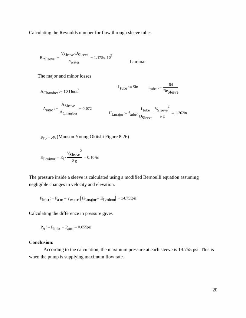
Calculating the Reynolds number for flow through sleeve tubes
Laminar
The major and minor losses
The pressure inside a sleeve is calculated using a modified Bernoulli equation assuming
negligible changes in velocity and elevation.
Calculating the difference in pressure gives
Conclusion:
According to the calculation, the maximum pressure at each sleeve is 14.755 psi. This is
when the pump is supplying maximum flow rate.
HLmajor ftube
Ltube
DSleeve
VSleeve
2
2 g 1.362in
(Munson Young Okiishi Figure 8.26)
ReSleeve
VSleeve DSleeve
water
1.175 103
Ltube 9in ftube64
ReSleeve
AChamber 10 11 mm
2
Aratio
ASleeve
AChamber
0.072
KL .48
HLminor KL
VSleeve2
2 g 0.167in
PInlet Patm water HLmajor HLminor 14.755psi
P PInlet Patm 0.055psi
21
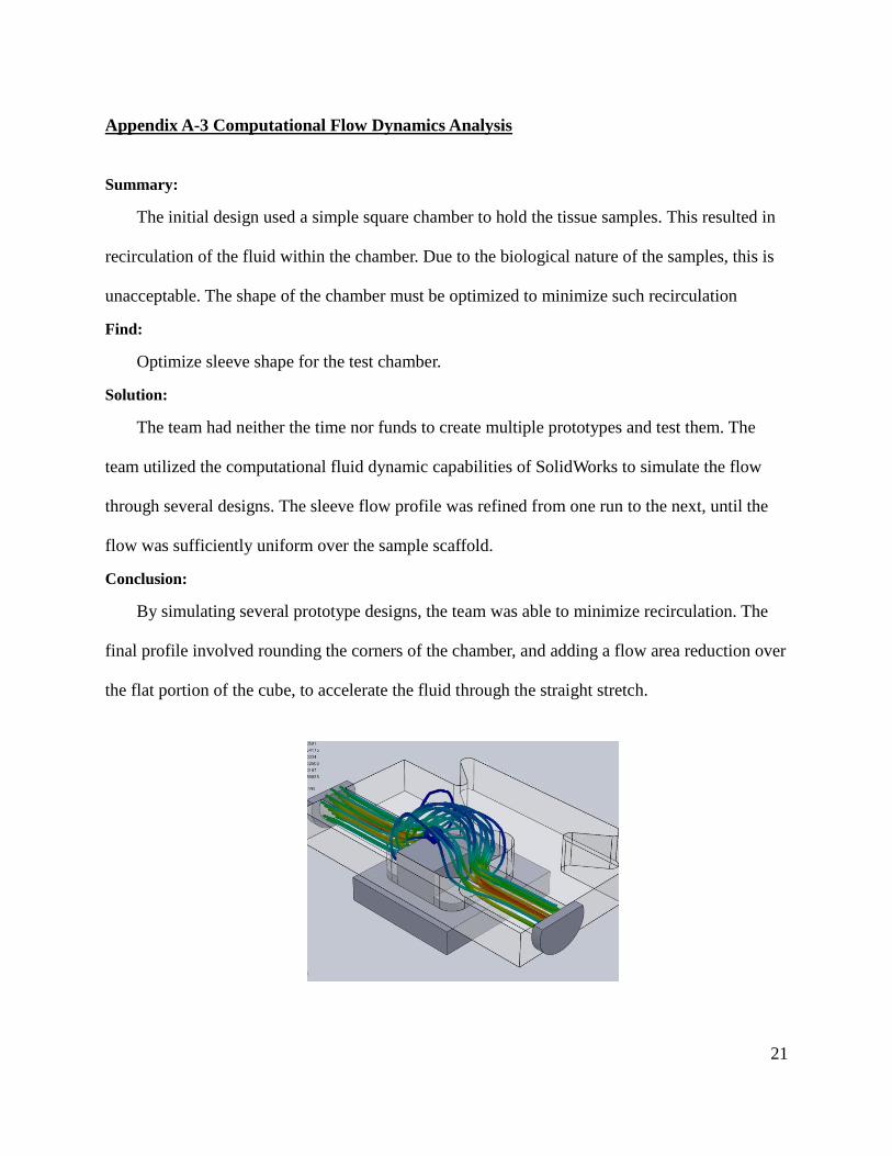
Appendix A-3 Computational Flow Dynamics Analysis
Summary:
The initial design used a simple square chamber to hold the tissue samples. This resulted in
recirculation of the fluid within the chamber. Due to the biological nature of the samples, this is
unacceptable. The shape of the chamber must be optimized to minimize such recirculation
Find:
Optimize sleeve shape for the test chamber.
Solution:
The team had neither the time nor funds to create multiple prototypes and test them. The
team utilized the computational fluid dynamic capabilities of SolidWorks to simulate the flow
through several designs. The sleeve flow profile was refined from one run to the next, until the
flow was sufficiently uniform over the sample scaffold.
Conclusion:
By simulating several prototype designs, the team was able to minimize recirculation. The
final profile involved rounding the corners of the chamber, and adding a flow area reduction over
the flat portion of the cube, to accelerate the fluid through the straight stretch.

22
Appendix A–4 Sleeve Stress Analysis
Summary:
The sample sleeves project from the sides of the carrier tray. When the bioreactor applies
compressive loads to the scaffold structures, the sample sleeves can be subjected to load as
though they were cantilevered beams. The factor of safety of the design must be determined to
ensure it will take the applied loading without breaking.
Given:
The applied load will be less than 10N
The narrowest part of the dovetail shape is 4.6mm, with a height of 9.25 mm
Acrylic Yield Strength is110 MPa on average, Shear Strength is 62 MPa
Load is applied approximately 4.2 mm from the clamped dovetail.
Find:
Factor of Safety
Solution:
An analysis of the design was performed using SolidWorks integrated finite element analysis
capabilities. It was determined that the safety factor of the design was 46. This is high enough
that neither moderately large errors in the software analysis nor statistical variances in the
strength of the polymer compound would not result in failure.

23
Appendix B – Part Drawings
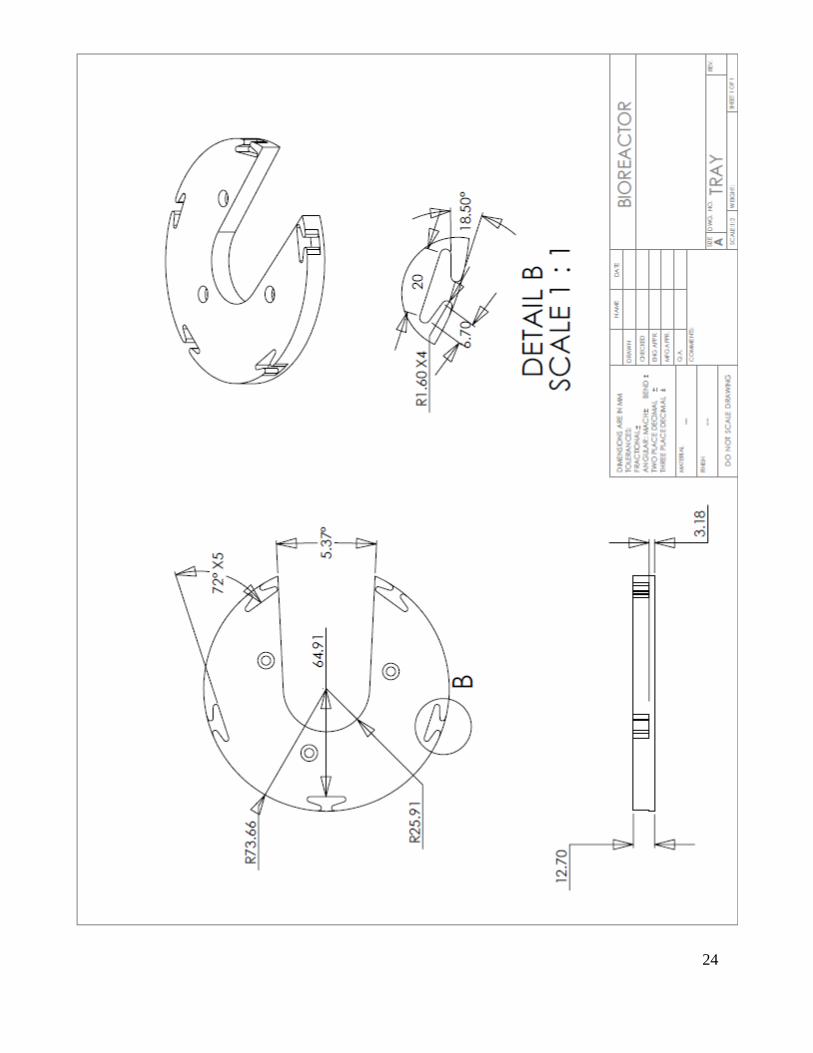
24
25

26

27
28

29
30
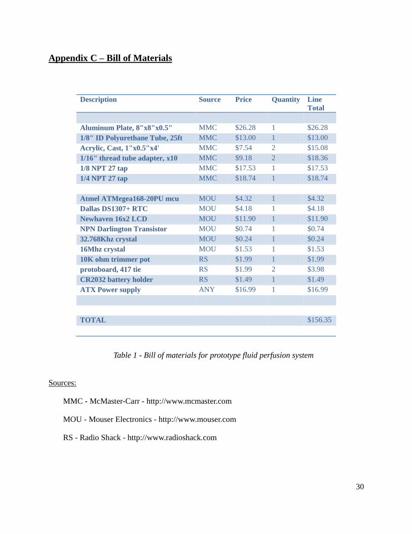
Appendix C – Bill of Materials
Description Source Price Quantity Line
Total
Aluminum Plate, 8"x8"x0.5" MMC $26.28 1 $26.28
1/8" ID Polyurethane Tube, 25ft MMC $13.00 1 $13.00
Acrylic, Cast, 1"x0.5"x4' MMC $7.54 2 $15.08
1/16" thread tube adapter, x10 MMC $9.18 2 $18.36
1/8 NPT 27 tap MMC $17.53 1 $17.53
1/4 NPT 27 tap MMC $18.74 1 $18.74
Atmel ATMegea168-20PU mcu MOU $4.32 1 $4.32
Dallas DS1307+ RTC MOU $4.18 1 $4.18
Newhaven 16x2 LCD MOU $11.90 1 $11.90
NPN Darlington Transistor MOU $0.74 1 $0.74
32.768Khz crystal MOU $0.24 1 $0.24
16Mhz crystal MOU $1.53 1 $1.53
10K ohm trimmer pot RS $1.99 1 $1.99
protoboard, 417 tie RS $1.99 2 $3.98
CR2032 battery holder RS $1.49 1 $1.49
ATX Power supply ANY $16.99 1 $16.99
TOTAL $156.35
Table 1 - Bill of materials for prototype fluid perfusion system
Sources:
MMC - McMaster-Carr - http://www.mcmaster.com
MOU - Mouser Electronics - http://www.mouser.com
RS - Radio Shack - http://www.radioshack.com

31
Appendix D – PDS Summary
Requirement Customer Metric Target Target Basis Verification
Performance
Flow Rate Dr. Kohles mL/min >4 Journal Article Prototype
Unattended
Run time
Bioengineering
Research Team Days >7 Sponsor Design
Adjustable
Run Interval Dr. Kohles Hours
Continuous to
72 hrs Sponsor Design
Environment
Able to
withstand
elevated
temperatures
Dr. Kohles °C 50 Incubator
Specifications
Design/Material
Selection
Able to
withstand
wide range of
CO2 Levels
Dr. Kohles % 0.2-20 Incubator
Specifications
Design/Material
Selection
Able to
withstand
wide range of
O2 Levels
Dr. Kohles % 5-20 Incubator
Specifications
Design/Material
Selection
Able to
withstand
high humidity
Dr. Kohles %RH 95 Incubator
Specifications
Design/Material
Selection
Installation And Maintenance
Number of
people needed
to install
Bioengineering
Research Team # of people 1 Research Team Prototype
Open
incubator
time needed to
replace any
failed
component
Dr. Kohles Minutes <15 Sponsor Prototype
Time needed
to
disassemble,
clean, and
reassemble
Bioengineering
Research Team Minutes <180 Sponsor Prototype
Manufacturing
Cost Dr. Kohles USD$ <1,000 Sponsor
Budget Design
Can be made
in PSU
machine shop
Bioengineering
Research Team --
No outside
manufacturing Sponsor Design

32
Requirement Customer Metric Target Target Basis Verification
Physical Specifications
Width Dr. Kohles mm <520 Incubator
Specifications Design
Depth Dr. Kohles mm <426 Incubator
Specifications Design
Height Dr. Kohles Mm <690 Incubator
Specifications Design
Weight of any
component
Bioengineering
Research Team Lbf <30
Easy 1 person
installation Design

33
Appendix E – Concept Generation and Selection
The internal search portion of the product development process consisted of several steps.
The team started by discussing ways in which the unique challenges presented by the design
requirements could be overcome. The team then spent a week independently developing new
ideas. During the following weekly meeting, the ideas were presented to the group, and
discussed. A further brainstorming session took place during the meeting, and the next iteration
debated. The team settled on six final contenders.
Fluid tank – Rather than utilize individual sample sleeves, all samples are submerged in a
large common pool of nutrient solution
Dovetail – This system utilizes a tool less mounting system to attach the sleeves to the
outer ring of the sample tray.
Slot ports – Attaching machined rectangular tubes to the rear surface of the sleeves
allowed this design to avoid some of the potential tangling issues, and may help minimize
fluid recirculation
Raised sleeve – By lifting the sample sleeves above the surface of the carrier tray, this
design facilitates the needed access to the side panels of the sleeves.
Raised tray – Similar to the raised design, this system drops sleeves below the tray by
lifting the carrier with a horseshoe. This both allows access to the side panels, and gives
an alternative hose routing option under the carrier tray.
Channel routing – Machining the fluid flow channels into the surface of the tray, and then
capping them with a secondary lid, minimized use of hoses in this design.
After a final panel of six candidates was selected, a scoring matrix was used to

34
objectively evaluate the ability of each design to handle the challenges presented. The team
assigned a numeric value to each of the primary categories of criteria, the sum of which yielded
an overall score for each design. The highest score determined the winner.
Top-Level Final Design Evaluation and Selection
The process of selecting the final design consisted several steps. First the team identified
what criteria should be followed in the selection process. After meeting with the customer over a
period of time the team had a vivid idea of the main customer requirements which were listed in
our product design specification document. The customer made it clear that the main goal is to
make a fluid perfusion system that is easy to install and maintain and that interfaces with the
current bioreactor system. The team was also required to stick to the budget provided by the
sponsor. Therefore, the main design selection criteria according to the PDS are:
1. Maintenance: All parts of the perfusion system have to be easily cleaned,
accessible and have satisfactory service lifetimes.
2. Installation: The system has to interface with the existing device. The process of
system disassembly and reassembly for maintenance purposes or for sample
replacement has to be simple and quick.
3. Cost: All purchased parts and materials, fabrication, prototyping and testing
processes are funded with a 1000 USD budget.
All design specifications described in the PDS document were revisited before the design
process began to make sure that all the proposed designs comply with the main specifications as
described by the customer. However, during the design process other criteria used in selecting

35
our final design were dictated by technical design parameters which the team found to be
necessary for creating an efficient and reliable system. These criteria are fluid recirculation,
tubing system and manufacturing and are explained below.
4. Fluid recirculation: Recirculation of the used fluid inside the sample wells has to
be minimized to guarantee that the samples are always supplied with fresh
nutritive fluid.
5. Tubing system: Fluid distribution system cannot interfere with other equipment
fixed to the bioreactor. In case of using medical tubing, tangling of the tubes has
to be avoided.
6. Manufacturing: The fabrication processes of implementing the prototypes and
final product need to be simple and time efficient. After the first designs were
finished, the team discussed the main pros and cons of each design and the results
are shown on the next page.

36
Rais
ed
Tray
Rais
ed
Sle
eve
Dove-T
ail
Slo
t P
orts
Ch
an
nel
Rou
tin
gF
luid
Tan
k
Main
Ad
van
tages
• H
angin
g t
he s
leeves
pro
vid
es
more
space
for
connecti
ng t
he
tubes.
• E
xis
ting t
ray c
an b
e
use
d.
• A
ccess
ing t
he
sleeves
from
beneath
the t
ray a
void
s
inte
rfere
nce b
etw
een
the t
ubin
g a
nd t
he
actu
ato
rs.
• R
ais
ing t
he s
leeves
pro
vid
es
more
space
for
connecti
ng t
he
tubes.
• A
cry
lic is
cheap
and e
asy
to f
abri
cate
.
• Sle
eves
can b
e o
f
larg
er
volu
me.
• T
ube c
onnecti
ons
can b
e e
asi
ly
checked.
• C
anti
leveri
ng t
he
sleeves
pro
vid
es
more
space f
or
connecti
ng t
he t
ubes.
• N
ot
too m
any
rest
ricti
ons
on t
he
sleeve s
ize.
• Sam
ple
s are
subje
cte
d t
o a
dir
ect
cro
ss f
low
.
• Sle
eves
are
easy
to
inst
all a
nd r
epla
ce.
• T
ube c
onnecti
ons
can b
e e
asi
ly
checked.
• N
ot
too m
any
rest
ricti
ons
on t
he
sleeve s
ize.
• E
asy
to inst
all.
• T
ube c
onnecti
ons
can b
e e
asi
ly
checked.
• T
angling is
reduced
by t
he u
se o
f sl
ot
port
s and s
hort
hose
s.
• N
o t
angling o
f
tubes.
• C
urr
ent
tray c
an b
e
modif
ied t
o f
it w
ith
the n
ew
syst
em
.
• N
o t
angling o
f
tubes.
• C
an h
old
vari
ous
sam
ple
siz
es.
Main
Dis
ad
van
tages
• A
ssem
bling a
nd
dis
ass
em
bling t
he
sleeves
are
tim
e
consu
min
g.
• D
iffi
cult
to c
heck
connecti
ons
hid
den
undern
eath
the t
ray.
• A
ssem
bling a
nd
dis
ass
em
bling t
he
sleeves
are
tim
e
consu
min
g.
• T
ubes
can b
e e
asi
ly
tangle
d t
ogeth
er.
• T
he t
ray a
nd
bra
ckets
ass
em
bly
is
too f
ragile.
• R
equir
es
fabri
cati
ng
a n
ew
tra
y.
• R
equir
es
fabri
cati
ng
a n
ew
tra
y.
• D
iffi
cult
and
expensi
ve t
o
fabri
cate
.
• Slo
t port
connecto
rs
are
too f
ragile.
• R
equir
es
fabri
cati
ng
a n
ew
tra
y.
• D
iffi
cult
to
fabri
cate
.
• D
iffi
cult
to d
ete
ct
leakage in t
ubes
and
dis
connecti
ons
hid
den u
ndern
eath
the c
over.
• T
akin
g o
ut
the
tubes
to b
e c
leaned
requir
es
unsc
rew
ing
the c
over
whic
h is
tim
e c
onsu
min
g.
• D
iffi
cult
and
expensi
ve t
o
fabri
cate
.
• O
nly
use
d in t
he
case
of
stati
c f
luid
.

37
Finally, a scoring matrix was used to objectively evaluate the ability of each design to
handle the challenges presented. The team assigned a numeric value to each of the primary
categories of criteria, the sum of which yielded an overall score for each design.
Top Level Scoring Matrix
The final design selected to move forward to the final refinement stage was the dovetail
system. This was selected due to the design’s advantage in ease of manufacture, flexibility in
sample type and shape, quick setup and repair, and ease of access to the side panel.
PDS Criteria Raised Tray Raised Sleeve Dove-Tail Slot Ports Channel Routing Fluid Tank
Maintenance 5 4 5 3 2 1
Installation 4 4 5 4 3 1
Cost 2 3 3 3 2 1
Fluid Recirculation 3 3 4 5 5 1
Tubing 3 3 3 4 4 4
Manufacturing 3 3 3 1 1 1
Total 20 20 23 20 17 9
38
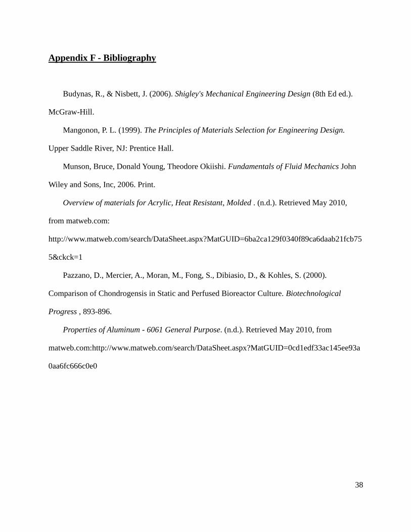
Appendix F - Bibliography
Budynas, R., & Nisbett, J. (2006). Shigley's Mechanical Engineering Design (8th Ed ed.).
McGraw-Hill.
Mangonon, P. L. (1999). The Principles of Materials Selection for Engineering Design.
Upper Saddle River, NJ: Prentice Hall.
Munson, Bruce, Donald Young, Theodore Okiishi. Fundamentals of Fluid Mechanics John
Wiley and Sons, Inc, 2006. Print.
Overview of materials for Acrylic, Heat Resistant, Molded . (n.d.). Retrieved May 2010,
from matweb.com:
http://www.matweb.com/search/DataSheet.aspx?MatGUID=6ba2ca129f0340f89ca6daab21fcb75
5&ckck=1
Pazzano, D., Mercier, A., Moran, M., Fong, S., Dibiasio, D., & Kohles, S. (2000).
Comparison of Chondrogensis in Static and Perfused Bioreactor Culture. Biotechnological
Progress , 893-896.
Properties of Aluminum - 6061 General Purpose. (n.d.). Retrieved May 2010, from
matweb.com:http://www.matweb.com/search/DataSheet.aspx?MatGUID=0cd1edf33ac145ee93a
0aa6fc666c0e0