automated boundary layer mesh generation for simulation of
TRANSCRIPT
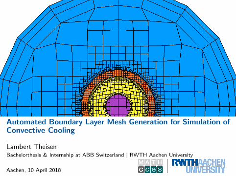
Automated Boundary Layer Mesh Generation for Simulation ofConvective Cooling
Lambert TheisenBachelorthesis & Internship at ABB Switzerland | RWTH Aachen University
Aachen, 10 April 2018
Table of Contents
1 Motivation
2 Project Context
3 Automated Mesh GenerationSnappyHexMesh in OpenFOAMIterative Meshing ApproachBase Mesh RefinementSurface and Feature SnappingBoundary Layer Addition
4 Simulation of Natural ConvectionSimulation Results
5 Limitations in Automation WorkflowExample: Transformer MeshBoundary Layer Inspection
6 Conclusion and Future Work
7 References
Lambert Theisen | Automated Boundary Layer Mesh Generation for Simulation of Convective Cooling | 2/21

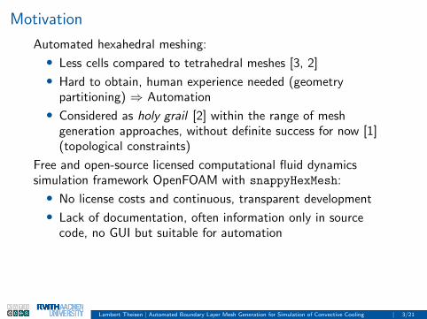
Motivation
Automated hexahedral meshing:
• Less cells compared to tetrahedral meshes [3, 2]
• Hard to obtain, human experience needed (geometrypartitioning) ⇒ Automation
• Considered as holy grail [2] within the range of meshgeneration approaches, without definite success for now [1](topological constraints)
Free and open-source licensed computational fluid dynamicssimulation framework OpenFOAM with snappyHexMesh:
• No license costs and continuous, transparent development
• Lack of documentation, often information only in sourcecode, no GUI but suitable for automation
⇒ Development of automation software to generate OpenFOAM’sinput data, necessary for meshing and simulation steps:
• 73% of analysis time spent for meshing related tasks [4]
Lambert Theisen | Automated Boundary Layer Mesh Generation for Simulation of Convective Cooling | 3/21

Project Context
CAD software
Analysis file (e.g. in TBX-format)
Preprocessor software tbx2openfoam
Meshing input data Simulation input data
Mesh generation in-cluding snappyHexMesh
Final meshSimulation of natural convectionwith chtMultiRegionFoam solver
Simulation results
Meshing Simulation
OpenFOAM
1
Lambert Theisen | Automated Boundary Layer Mesh Generation for Simulation of Convective Cooling | 4/21
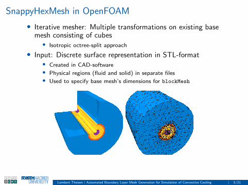
SnappyHexMesh in OpenFOAM
• Iterative mesher: Multiple transformations on existing basemesh consisting of cubes• Isotropic octree-split approach
• Input: Discrete surface representation in STL-format• Created in CAD-software• Physical regions (fluid and solid) in separate files• Used to specify base mesh’s dimensions for blockMesh
Lambert Theisen | Automated Boundary Layer Mesh Generation for Simulation of Convective Cooling | 5/21
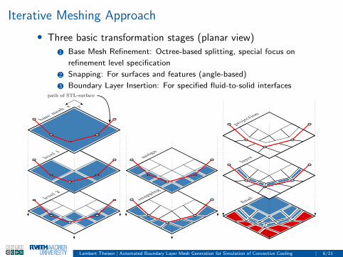
Iterative Meshing Approach
• Three basic transformation stages (planar view)
1 Base Mesh Refinement: Octree-based splitting, special focus on
refinement level specification
2 Snapping: For surfaces and features (angle-based)
3 Boundary Layer Insertion: For specified fluid-to-solid interfaces
level
2
level
1
base
meshx y
path of STL-surface
1
snapp
ing
assign
1
final
layer
projectio
n
1
Lambert Theisen | Automated Boundary Layer Mesh Generation for Simulation of Convective Cooling | 6/21
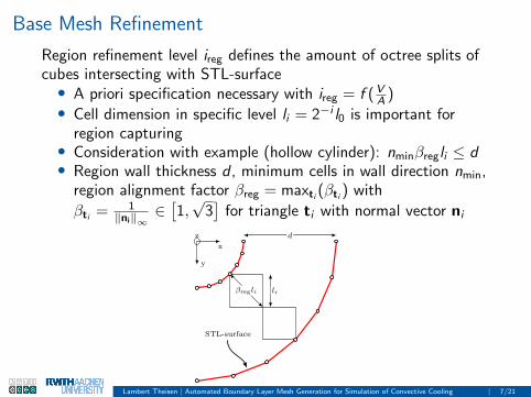
Base Mesh Refinement
Region refinement level ireg defines the amount of octree splits ofcubes intersecting with STL-surface• A priori specification necessary with ireg = f (V
A )• Cell dimension in specific level li = 2−i l0 is important for
region capturing• Consideration with example (hollow cylinder): nminβregli ≤ d• Region wall thickness d , minimum cells in wall direction nmin,
region alignment factor βreg = maxti (βti ) with
βti = 1‖ni‖∞
∈[1,√
3]
for triangle ti with normal vector nid
βregli li
STL-surface
x
y
z
1
Lambert Theisen | Automated Boundary Layer Mesh Generation for Simulation of Convective Cooling | 7/21

Level Calculation
We end up with i ≥log
(d
nminβreg l0
)log( 1
2 )• Wall thickness d still unknown
• Characteristic length for cuboid with side lengths a, b, c ∈ R• lchar = V
A = 12( 1
a + 1b + 1
c )• Cube lchar,cube = a
6• Thin plate lchar,thin = lim
b,c→∞1
2( 1
a+ 1
b+ 1
c)
= a2
• Two extreme cases, no fractals ⇒ Assume 2lchar ≤ d ≤ 6lchar
Final refinement level estimation: ireg =
⌈log
(2lchar
nminβreg l0
)log( 1
2 )
⌉• Estimation tested with an example consisting of four regions
Lambert Theisen | Automated Boundary Layer Mesh Generation for Simulation of Convective Cooling | 8/21
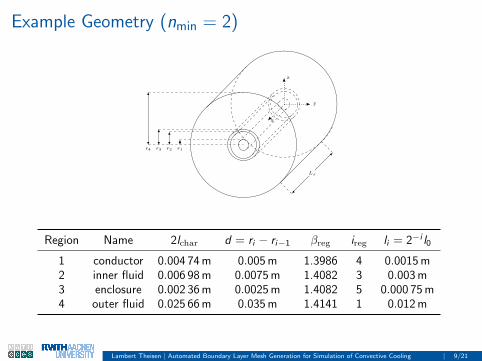
Example Geometry (nmin = 2)
x
y
z
Lx
r1r2r3r4
1
Region Name 2lchar d = ri − ri−1 βreg ireg li = 2−i l0
1 conductor 0.004 74 m 0.005 m 1.3986 4 0.0015 m2 inner fluid 0.006 98 m 0.0075 m 1.4082 3 0.003 m3 enclosure 0.002 36 m 0.0025 m 1.4082 5 0.000 75 m4 outer fluid 0.025 66 m 0.035 m 1.4141 1 0.012 m
Lambert Theisen | Automated Boundary Layer Mesh Generation for Simulation of Convective Cooling | 9/21
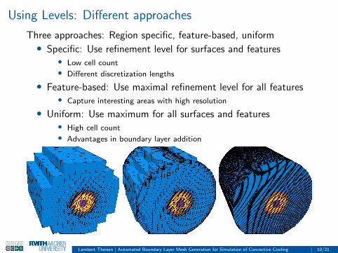
Using Levels: Different approaches
Three approaches: Region specific, feature-based, uniform• Specific: Use refinement level for surfaces and features
• Low cell count• Different discretization lengths
• Feature-based: Use maximal refinement level for all features• Capture interesting areas with high resolution
• Uniform: Use maximum for all surfaces and features• High cell count• Advantages in boundary layer addition
Lambert Theisen | Automated Boundary Layer Mesh Generation for Simulation of Convective Cooling | 10/21

Surface and Feature Snapping
• Second step in snappyHexMesh’s pipeline
• Transformation of castellated mesh to approximate thespecified geometry• Special focus on feature snapping
• Features a priori obtained from surface data with feature angle• nsnap,feat = 0 vs. nsnap,feat = 5
Lambert Theisen | Automated Boundary Layer Mesh Generation for Simulation of Convective Cooling | 11/21

Boundary Layer Addition: Progressive Approach
• Different definitions together with layer count nlay: expansionratio λ, overall thickness Llay, first layer thickness llay,1, lastlayer thickness llay,n (choose two, overdetermination)
• Optimal: Progressive transition from last layer to first inner
cell withlcell,1
llay,nlay
!= λ
• A priori calculation of overall thickness with given nlay and λ:• Layer thickness Llay = 2−ireg l0µlay
• µlay = λnlay−1λnlay (λ−1)
as a ratio of first cell side length to overall layer
thickness
llay,1
llay,2 = λllay,1
llay,3 = λllay,2
Llayλ−1
λ3−1
fluid to solid interface
1
Lambert Theisen | Automated Boundary Layer Mesh Generation for Simulation of Convective Cooling | 12/21

Example
• Test with region-specific refinement approach and three layers• Different layer thicknesses
• Limitations (five vs. seven layers)• Especially in closed volumes• Mesh quality not satisfied
Lambert Theisen | Automated Boundary Layer Mesh Generation for Simulation of Convective Cooling | 13/21

Fully Flow Enabled Simulation
Conjugate heat transfer including turbulence & radiation,automatic case setup with information from thermal analysis file• Fluid movement above the heat source q̇v in solids• Cooling by natural convection• Radial in inner closed volume (less fluid movement)
Temperature distribution [K] Velocity magnitude ‖u‖2
[ms
]Lambert Theisen | Automated Boundary Layer Mesh Generation for Simulation of Convective Cooling | 14/21

Fully Flow Enabled Simulation
• Some vertices• Interesting: Temperature at outer walls
• Thermal safety ratings• Environmental impact of a thermal system
Velocity streamlines and vectors Three-dimensional overview
Lambert Theisen | Automated Boundary Layer Mesh Generation for Simulation of Convective Cooling | 15/21

Limitations in Automation Workflow
Whole meshing and simulation workflow is fully automated forarbitrary geometries, however there are limitations especially inmeshing step• More complex example often have large dimension variations
• For example: Small regions surrounded by large airbox• Isotropic octree-approach not optimal in such cases• Large cell count caused by refinement level transitions
• Consider example transformer geometry• Airbox diameter 5 m, thinnest region thickness 0.025 m
Lambert Theisen | Automated Boundary Layer Mesh Generation for Simulation of Convective Cooling | 16/21

Transformer Meshing Results
Mesh consists of 5 371 407 cells formed by 16 594 075 faces and5 847 813 points
• Airbox refinement level 1, maximal refinement level 9
• Many cells used for solid regions
• Additional region refinement in fluid regions needed
The used model with lmin = 0.025 m is actually a merged versionof a real model with lmin = 0.005 m
• At least two additional refinement levels needed
• Resulting in even more cells: > 50 000 000Lambert Theisen | Automated Boundary Layer Mesh Generation for Simulation of Convective Cooling | 17/21
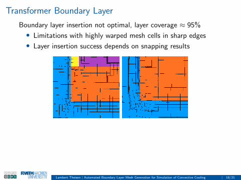
Transformer Boundary Layer
Boundary layer insertion not optimal, layer coverage ≈ 95%
• Limitations with highly warped mesh cells in sharp edges
• Layer insertion success depends on snapping results
Lambert Theisen | Automated Boundary Layer Mesh Generation for Simulation of Convective Cooling | 18/21
Conclusion and Future Work
Aim of project: Fully automated meshing of arbitrary geometrieswith following simulation suitable for heat conduction simulationsincluding natural convection
• Implementation of C++ automation framework
• Dictionary-creation (OpenFOAM input) for meshing andsimulation
• Thermal studies directly from CAD-program with analysis file
Challenges, limitations and future work:• Isotropic octree-split approach results in large cell count
• Drop conformity requirement to avoid refinement transitions• Use tetrahedral mesh and insert prism as boundary layer
• Mesh resolution in fluid regions hard to estimate• Flow direction prediction with gravity• Adaptive mesh refinement based on flow properties
• Error handling hard with only a priori automation• Parallel automation to monitor success of snappyHexMesh
Lambert Theisen | Automated Boundary Layer Mesh Generation for Simulation of Convective Cooling | 19/21

References
[1] C. G. Armstrong, H. J. Fogg, C. M. Tierney, and T. T. Robinson. Common Themes in Multi-block Structured
Quad/Hex Mesh Generation. Procedia Engineering, 124:70–82, 2015. URL
http://www.sciencedirect.com/science/article/pii/S1877705815032245.
[2] T. Blacker. Automated Conformal Hexahedral Meshing Constraints, Challenges and Opportunities. Engineering
with Computers, 17(3):201–210, 2001. URL https://link.springer.com/article/10.1007/PL00013384.
[3] M. Kremer, D. Bommes, I. Lim, and L. Kobbelt. Advanced Automatic Hexahedral Mesh Generation from
Surface Quad Meshes. In Proceedings of the 22nd International Meshing Roundtable, pages 147–164.
Springer, 2014. URL https://link.springer.com/chapter/10.1007/978-3-319-02335-9_9.
[4] S. J. Owen, B. W. Clark, D. J. Melander, M. Brewer, J. F. Shepherd, K. Merkley, C. Ernst, and R. Morris. An
Immersive Topology Environment for Meshing. In Proceedings of the 16th International Meshing Roundtable,
pages 553–577. Springer, Berlin, Heidelberg, 2008. URL
https://link.springer.com/chapter/10.1007/978-3-540-75103-8_31.
Lambert Theisen | Automated Boundary Layer Mesh Generation for Simulation of Convective Cooling | 20/21

Switzerland
Thank You
.
Lambert Theisen | Automated Boundary Layer Mesh Generation for Simulation of Convective Cooling | 21/21
Switzerland
Thank You
.
Lambert Theisen | Automated Boundary Layer Mesh Generation for Simulation of Convective Cooling | 21/21