automated adjustment of automotive seating structures references... · automated adjustment of...
TRANSCRIPT
2006 ABAQUS Users’ Conference 109
Automated Adjustment of Automotive Seating Structures
C. Brix
P+Z Engineering
Abstract: To satisfy passenger safety requirements, automotive seats are required to meet a large number of structural design criteria. They demand dynamic front and rear pulse sled tests including crash test dummies, luggage impact, as well as other quasi-static structural analyses. All these load configurations typically require a unique seat position.
A rapid implementation of frequent CAD updates has to be ensured to successfully support the design process. Therefore it is essential to define a modularized numerical FE-environment, which includes a universal seating structure to be employed throughout all investigations.
This approach introduces an Abaqus/Explicit meta model of a seating structure, which can be universally employed in all required load case environments. The seat is adjusted in its required position automatically by *NMAP transformations. They are calculated by an Excel-Tool that can produce every seat position within the seat’s reference point field taking into account longitudinal, height and tilt adjustment. This positioning avoids creating another full seat model with mostly redundant information, by simply providing transformation cards as add-on data. Since other components such as dummies, seat cushion or side airbags are also related to the seat kinematics, their transformations can be derived from the calculated seat transformations as well.
This concept accelerates the simulations response on new design data through the use of updates generated using the meta model only. A consistent model status for each load case is automatically ensured due to the uniqueness of the underlying meta model. This improves the process of analyzing seat structures in terms of efficiency, data consistency and flexibility. Keywords: automotive seating, transformation, NMAP, seat adjustment
110 2006 ABAQUS Users’ Conference
1. Introduction
By creating the contact between passenger and the car body, the seat structure is expected to contribute substantially to an optimal passenger safety capacity. Safety aspects play meanwhile a major role in the customers decision-making process for new cars. With an increasing public awareness of automobile safety aspects the authorities defined a number of legal requirements in the past years to enhance safety standards for future car developments.
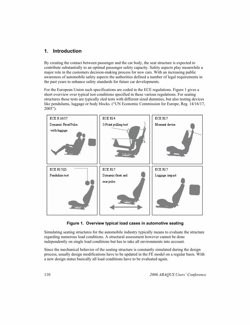
For the European Union such specifications are coded in the ECE regulations. Figure 1 gives a short overview over typical test conditions specified in these various regulations. For seating structures these tests are typically sled tests with different sized dummies, but also testing devices like pendulums, luggage or body blocks. (“UN Economic Commission for Europe, Reg. 14/16/17, 2005”).
Figure 1. Overview typical load cases in automotive seating
Simulating seating structures for the automobile industry typically means to evaluate the structure regarding numerous load conditions. A structural assessment however cannot be done independently on single load conditions but has to take all environments into account.
Since the mechanical behavior of the seating structure is constantly simulated during the design process, usually design modifications have to be updated in the FE model on a regular basis. With a new design status basically all load conditions have to be evaluated again.
2006 ABAQUS Users’ Conference 111
To provide competitive simulation services it is essential that such updates are rapidly realized also in the FE-model. Thus, a prompt feedback on the update’s impact in the overall performance of the structure has to be provided to reduce development time and relief cost pressure.
2. Modularized simulations environment
This chapter motivates the concept of a modularized simulation environment. Apart from modularizing interior positioning, which is discussed in this paper, that concept is more and more commonly used especially when objects under numerous load cases are considered. The idea is to assembly individual load case environments from universal FE-modules. These modules therefore have to provide their functionality correctly in any environment.
2.1 Motivation
• Less redundant information, more reliability, less mistakes (e.g. the seat structure will only physically appear once throughout all load cases)
• Implicit update on different load cases (e.g. update on the structure are automatically present for all load cases assemblies, due to their unique model usage)
• Higher potential for team-work processes (i.e. since organized in individual files, different load cases can be set up independently and simultaneously without redundancy)
• Higher flexibility to react on customer wishes
2.2 Strategies for identifying and defining modules
These modules are determined easily by following only one basic guideline:
• All references across files should be avoided. References across files may occur due to interactions (connections, contact, etc) between different modules. If they are inevitable the cross-reference data has to be written in an separate interface module which is only included when the specific interaction is required.
Taking the above guideline into account the following modules can be determined from load case environment in automotive seating:
Splitting up the model, in a “physical” sense:
• Seating structure without cushion including all the necessary entities describing physical and geometrical properties, definitions of local contacts or connections, and time history information
112 2006 ABAQUS Users’ Conference
• Seat cushion in undeformed shape when dummy seating is considered, or in dummy specific cushion deformation
• Belt includes the individual geometrical and physical properties of the belts for the different dummies employed
• Retention system includes safety components such as active pretension systems, retractors, sliprings connected to the BIW
• Dummy the individual crash test dummies employed, but also general loading devices such as luggage, body blocks or impactor pendulums.
• BIW the body-in-white structure
Model splitting in terms of boundary conditions, or time history information:
• BC the boundary conditions defined for the individual load cases which may be further split up into
• DBC displacement boundary condition
• FBC force boundary conditions (e.g. imposed acting forces for static load cases)
• VBC velocity boundary conditions (e.g. crash pulse)
• Global Connections including all connections that are present across separate parts e.g. a *Tie definition, into separate files
• Transformation including positioning definitions (e.g. transformation for the kinematic parts of the seat structure to represent different seat positions); this part will be discussed in detail in the following chapters
• Global Contact we recommend the use of the ALL ELEMENT BASED option in the *CONTACT INCLUSION definition so that contact interaction throughout the whole environment is ensured
2006 ABAQUS Users’ Conference 113
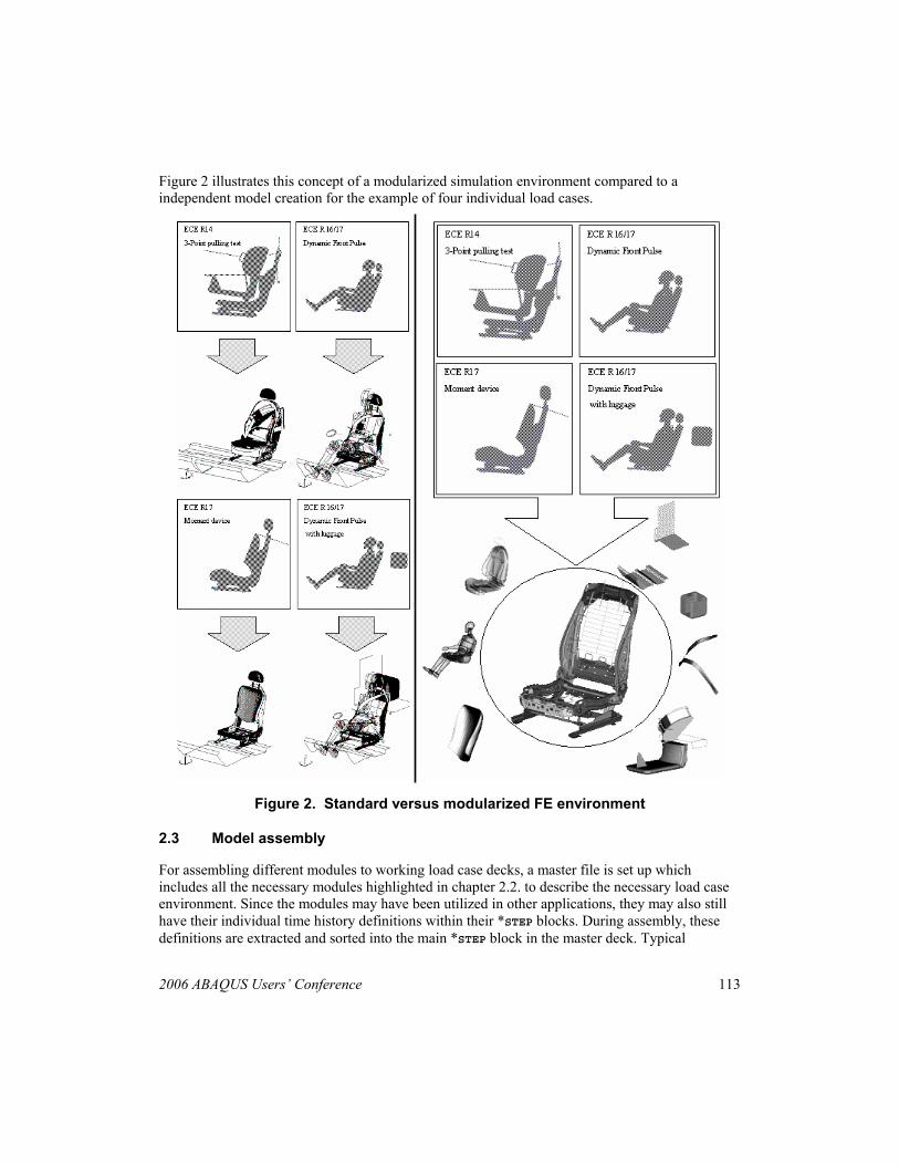
Figure 2 illustrates this concept of a modularized simulation environment compared to a independent model creation for the example of four individual load cases.
Figure 2. Standard versus modularized FE environment
2.3 Model assembly
For assembling different modules to working load case decks, a master file is set up which includes all the necessary modules highlighted in chapter 2.2. to describe the necessary load case environment. Since the modules may have been utilized in other applications, they may also still have their individual time history definitions within their *STEP blocks. During assembly, these definitions are extracted and sorted into the main *STEP block in the master deck. Typical
114 2006 ABAQUS Users’ Conference
examples for module specific time history definitions are certain output requests, contact property definitions or boundary conditions.
The use of e.g. perl scripts for automizing the assembly procedure is recommended.
3. Seat positioning
The specifications of different load cases typically also prescribe a predefined seat position adjustment. The load cases often require the employment of dummies of different sizes, so the seat position hast to be adjusted accordingly. For a different seat adjustment the relative position of numerous components change considerably. With a different seat kinematics the loads are therefore also transmitted differently into the car body. Also the resulting moments imposed on the structure change with a varying center of gravity of the seat and dummy. Therefore, the structural capacity of the seat will change with the position adjusted.
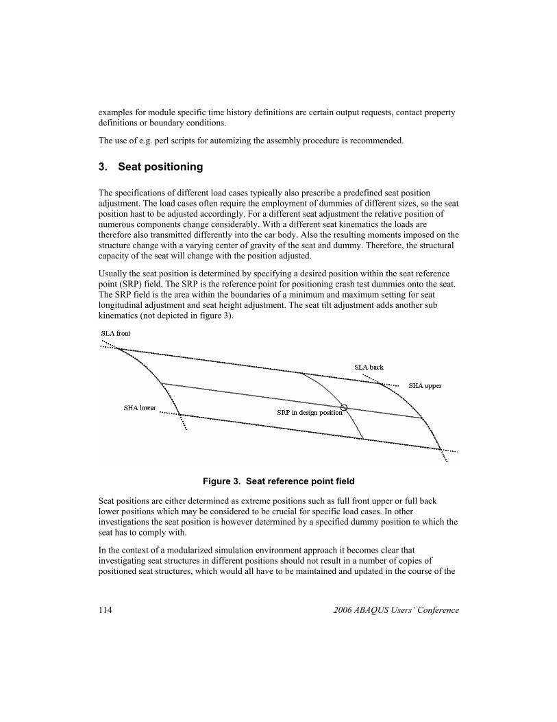
Usually the seat position is determined by specifying a desired position within the seat reference point (SRP) field. The SRP is the reference point for positioning crash test dummies onto the seat. The SRP field is the area within the boundaries of a minimum and maximum setting for seat longitudinal adjustment and seat height adjustment. The seat tilt adjustment adds another sub kinematics (not depicted in figure 3).
Figure 3. Seat reference point field
Seat positions are either determined as extreme positions such as full front upper or full back lower positions which may be considered to be crucial for specific load cases. In other investigations the seat position is however determined by a specified dummy position to which the seat has to comply with.
In the context of a modularized simulation environment approach it becomes clear that investigating seat structures in different positions should not result in a number of copies of positioned seat structures, which would all have to be maintained and updated in the course of the
2006 ABAQUS Users’ Conference 115
further development. On the other hand, every position has to be readily available since all load cases will be more less considered simultaneously during the project.
Therefore, in this paper we introduce the use of the seat module as a meta model in addition with specific *NMAP transformation modules that adjust the seat from it’s initial to its specified load case position. This approach avoids the creation of copies; all further changes to the design will still be done on the meta model.
3.1 Automotive front seat concepts
To produce the correct transformations the seat kinematics has to be determined and reproduced in a seat-positioning device. Therefore basic concepts of seat kinematics are introduced here. They are classified by the number of relevant degrees of freedom the structure provides. These are typically the seat’s longitudinal adjustment (SLA), height adjustment (SHA) tilting adjustment (STA) and the seat’s backrest adjustment (SBA).
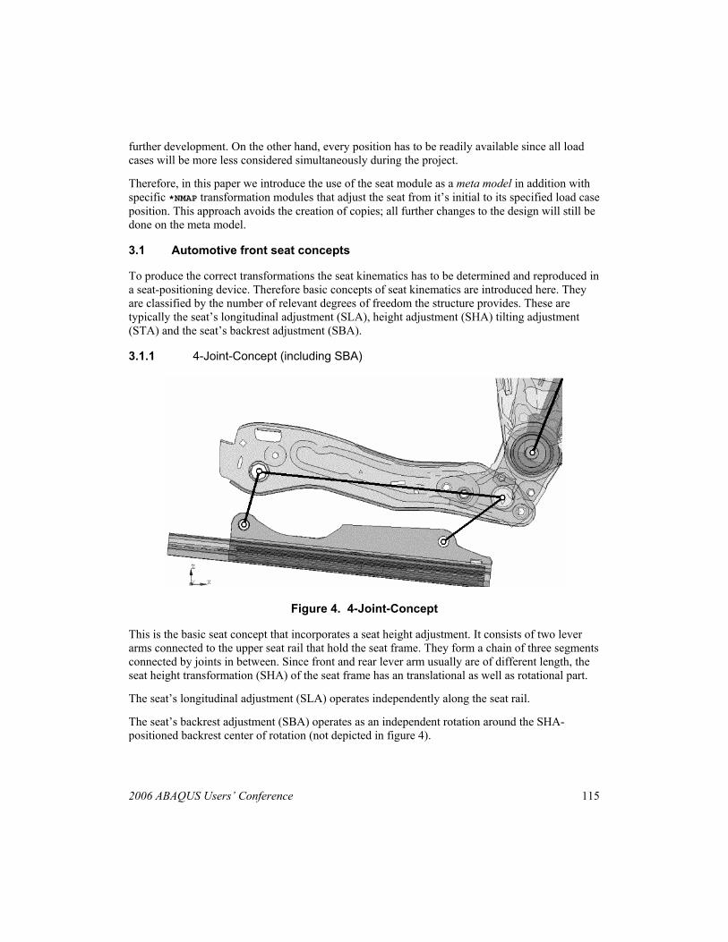
3.1.1 4-Joint-Concept (including SBA)
Figure 4. 4-Joint-Concept
This is the basic seat concept that incorporates a seat height adjustment. It consists of two lever arms connected to the upper seat rail that hold the seat frame. They form a chain of three segments connected by joints in between. Since front and rear lever arm usually are of different length, the seat height transformation (SHA) of the seat frame has an translational as well as rotational part.
The seat’s longitudinal adjustment (SLA) operates independently along the seat rail.
The seat’s backrest adjustment (SBA) operates as an independent rotation around the SHA-positioned backrest center of rotation (not depicted in figure 4).
116 2006 ABAQUS Users’ Conference
3.1.2 Concepts of seat kinematics with tilt adjustment (STA)
The following figures show two typical examples of seat kinematics with included seat tilt adjustment.
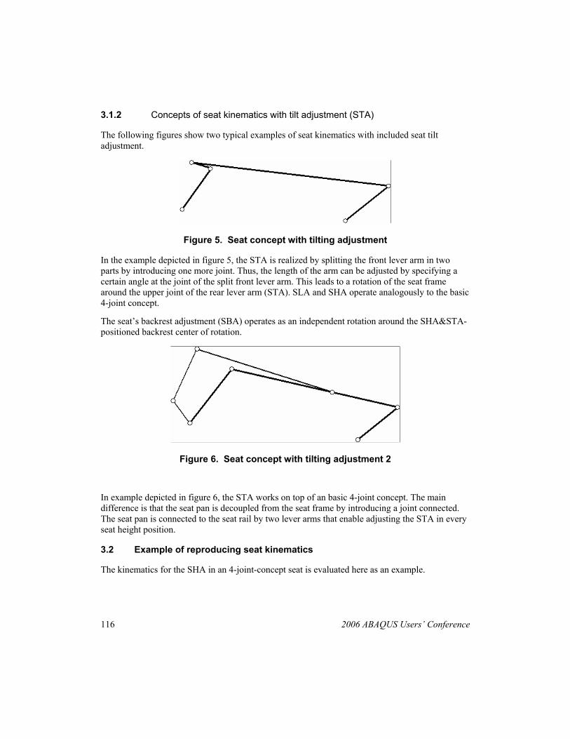
Figure 5. Seat concept with tilting adjustment
In the example depicted in figure 5, the STA is realized by splitting the front lever arm in two parts by introducing one more joint. Thus, the length of the arm can be adjusted by specifying a certain angle at the joint of the split front lever arm. This leads to a rotation of the seat frame around the upper joint of the rear lever arm (STA). SLA and SHA operate analogously to the basic 4-joint concept.
The seat’s backrest adjustment (SBA) operates as an independent rotation around the SHA&STA-positioned backrest center of rotation.
Figure 6. Seat concept with tilting adjustment 2
In example depicted in figure 6, the STA works on top of an basic 4-joint concept. The main difference is that the seat pan is decoupled from the seat frame by introducing a joint connected. The seat pan is connected to the seat rail by two lever arms that enable adjusting the STA in every seat height position.
3.2 Example of reproducing seat kinematics
The kinematics for the SHA in an 4-joint-concept seat is evaluated here as an example.
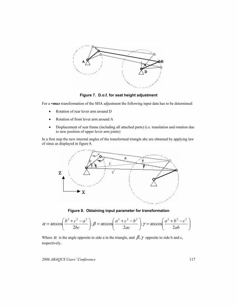
2006 ABAQUS Users’ Conference 117
Figure 7. D.o.f. for seat height adjustment
For a *NMAP transformation of the SHA adjustment the following input data has to be determined:
• Rotation of rear lever arm around D
• Rotation of front lever arm around A
• Displacement of seat frame (including all attached parts) (i.e. translation and rotation due to new position of upper lever arm joints)
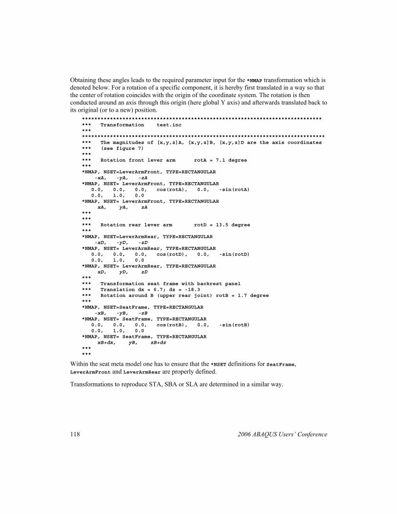
In a first step the new internal angles of the transformed triangle abc are obtained by applying law of sinus as displayed in figure 8.
Figure 8. Obtaining input parameter for transformation
⎟⎟⎠
⎞⎜⎜⎝
⎛ −+=bc
acb2
arccos222
α ; ⎟⎟⎠
⎞⎜⎜⎝
⎛ −+=ac
bca2
arccos222
β ; ⎟⎟⎠
⎞⎜⎜⎝
⎛ −+=ab
cba2
arccos222
γ
Where α is the angle opposite to side a in the triangle, and γβ , opposite to side b and c, respectively.
118 2006 ABAQUS Users’ Conference
Obtaining these angles leads to the required parameter input for the *NMAP transformation which is denoted below. For a rotation of a specific component, it is hereby first translated in a way so that the center of rotation coincides with the origin of the coordinate system. The rotation is then conducted around an axis through this origin (here global Y axis) and afterwards translated back to its original (or to a new) position.
***************************************************************************** *** Transformation test.inc *** ****************************************************************************** *** The magnitudes of [x,y,z]A, [x,y,z]B, [x,y,z]D are the axis coordinates *** (see figure 7) *** *** Rotation front lever arm rotA = 7.1 degree *** *NMAP, NSET=LeverArmFront, TYPE=RECTANGULAR -xA, -yA, -zA *NMAP, NSET= LeverArmFront, TYPE=RECTANGULAR 0.0, 0.0, 0.0, cos(rotA), 0.0, -sin(rotA) 0.0, 1.0, 0.0 *NMAP, NSET= LeverArmFront, TYPE=RECTANGULAR xA, yA, zA *** *** *** Rotation rear lever arm rotD = 13.5 degree *** *NMAP, NSET=LeverArmRear, TYPE=RECTANGULAR -xD, -yD, -zD *NMAP, NSET= LeverArmRear, TYPE=RECTANGULAR 0.0, 0.0, 0.0, cos(rotD), 0.0, -sin(rotD) 0.0, 1.0, 0.0 *NMAP, NSET= LeverArmRear, TYPE=RECTANGULAR xD, yD, zD *** *** Transformation seat frame with backrest panel *** Translation dx = 6.7; dz = -18.3 *** Rotation around B (upper rear joint) rotB = 1.7 degree *** *NMAP, NSET=SeatFrame, TYPE=RECTANGULAR -xB, -yB, -zB *NMAP, NSET= SeatFrame, TYPE=RECTANGULAR 0.0, 0.0, 0.0, cos(rotB), 0.0, -sin(rotB) 0.0, 1.0, 0.0 *NMAP, NSET= SeatFrame, TYPE=RECTANGULAR xB+dx, yB, zB+dz *** ***
Within the seat meta model one has to ensure that the *NSET definitions for SeatFrame, LeverArmFront and LeverArmRear are properly defined.
Transformations to reproduce STA, SBA or SLA are determined in a similar way.
2006 ABAQUS Users’ Conference 119
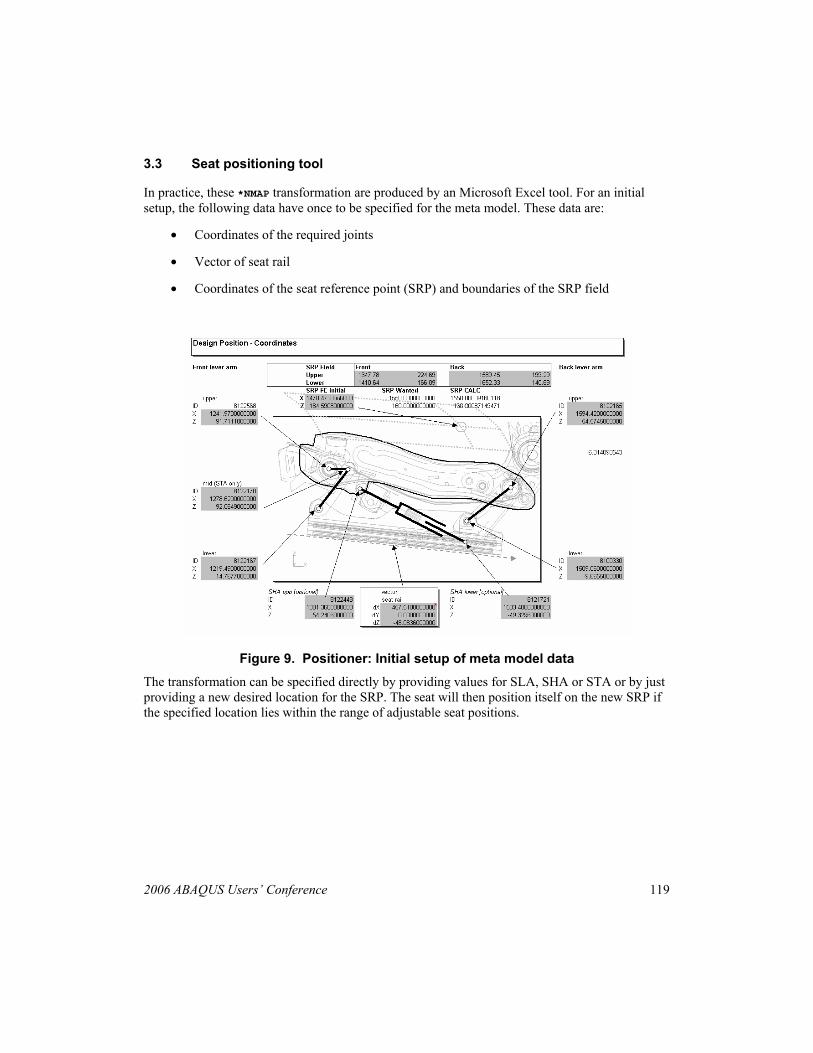
3.3 Seat positioning tool
In practice, these *NMAP transformation are produced by an Microsoft Excel tool. For an initial setup, the following data have once to be specified for the meta model. These data are:
• Coordinates of the required joints
• Vector of seat rail
• Coordinates of the seat reference point (SRP) and boundaries of the SRP field
Figure 9. Positioner: Initial setup of meta model data The transformation can be specified directly by providing values for SLA, SHA or STA or by just providing a new desired location for the SRP. The seat will then position itself on the new SRP if the specified location lies within the range of adjustable seat positions.
120 2006 ABAQUS Users’ Conference
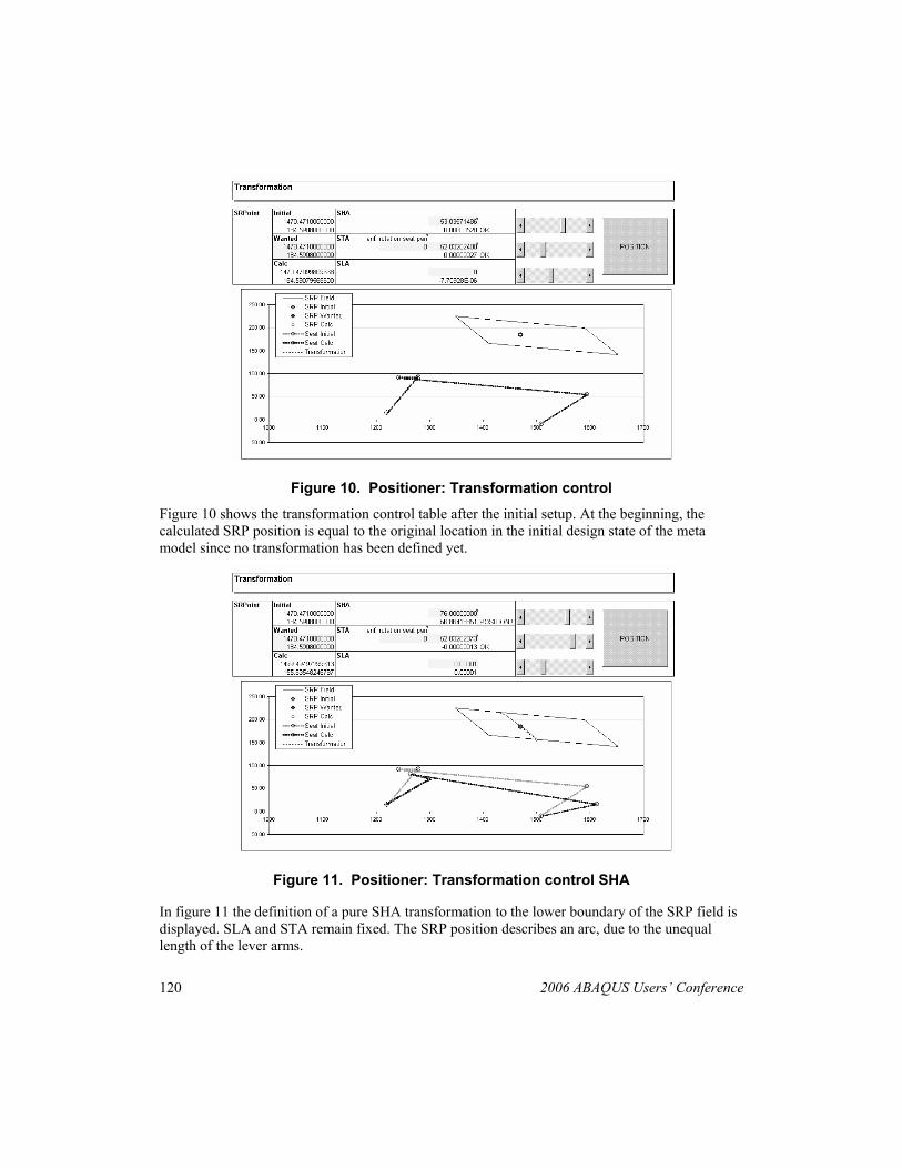
Figure 10. Positioner: Transformation control
Figure 10 shows the transformation control table after the initial setup. At the beginning, the calculated SRP position is equal to the original location in the initial design state of the meta model since no transformation has been defined yet.
Figure 11. Positioner: Transformation control SHA
In figure 11 the definition of a pure SHA transformation to the lower boundary of the SRP field is displayed. SLA and STA remain fixed. The SRP position describes an arc, due to the unequal length of the lever arms.
2006 ABAQUS Users’ Conference 121
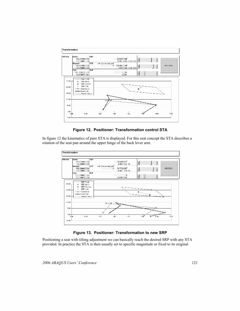
Figure 12. Positioner: Transformation control STA
In figure 12 the kinematics of pure STA is displayed. For this seat concept the STA describes a rotation of the seat pan around the upper hinge of the back lever arm.
Figure 13. Positioner: Transformation to new SRP
Positioning a seat with tilting adjustment we can basically reach the desired SRP with any STA provided. In practice the STA is then usually set to specific magnitude or fixed to its original
122 2006 ABAQUS Users’ Conference
value. When a certain SRP position is specified the seat can then be automatically adjusted to the new SRP as displayed in figure 13. At any time of the positioning session the current transformation can be exported into an ABAQUS formatted input deck, similar to the extract example shown in chapter 3.2. To run the seat in the specified position the transformation module has simply to be added to the model assembly. Transformation commands can be exported in different solver syntax such as Pamcrash or LS-Dyna, but especially also in form of session files for preprocessors. Currently an output of the transformation in form of a Hypermesh command file is supported. Running the command file in Hypermesh produces then a copy of the meta model in the desired position.
3.4 Seat related positioning
Another advantage of using *NMAP transformation for load case positioning is the fact that a number of required positioning activities in an automotive interior environment is directly related to the seat position.
Obviously all parts attached to seat structures such as the cushion or integrated side airbags follow exactly the kinematics of the underlying structure. To consider them for positioning, the *NSET definition of their nodes are added to the respective *NMAP transformation of the seat structure. For example a side airbag therefore shares the kinematic of the seat frame plus a possible rotation of the backrest.
Also parts, which are not directly attached to the seat structure, can be referenced in the transformations. Under certain circumstances this is the case for dummies and seat belts. When dummies are included in the positioning method one has to make sure that during positioning the angle between seat frame and seat backrest remain unchanged. If this is the case the relative position of deformed seat cushions to each other remains fixed as well, so the dummy will not penetrate the cushion surface in any position. For seat concepts with a seat pan fixed to the seat frame this is always the case provided the backrest is not rotated.
For seat concepts as illustrated in figure 6, where the pan is only attached by a hinge to the seat frame this angel changes by altering STA or SHA. If a dummy is still supposed to be included to the seat transformation we can choose to link STA to SHA. This is done in such a way so that small adjustments of the STA are enforced to enable a constant seat frame to backrest angel in all positions.
Seat belts are also suitable for being positioned together with the dummy since their relative position to the dummy pelvis and torso remains unchanged, too. Please note that this only applies for the belt in the vicinity of the dummy. The remaining parts of the seating belt, typically defined by *CONNECTOR type SLIPRING and RETRACTOR elements, since attached to the BIW, will not follow the dummy transformation and should be organized in a separate module.
2006 ABAQUS Users’ Conference 123
4. Conclusion
Organizing simulation projects in form of a modularized FEA environment has been widely employed within the automotive industry in the past years. A consistent adoption of this concept on seat structures however also requires the modularization of positioning information.
Nowadays the first preprocessor (e.g. GNS Generator) are available on the market that also allow seat positioning. Beside the fact that there is no STA supported, their approach is however a “physical” transformation embedded in the preprocessor environment to produce a positioned copy of the structure. This paper tries to highlight the advantages of using a transformable meta model over this approach, especially also due to the synergy effects explained in chapter 3.4 under seat related positioning.
The concept of positioning seat structures and kinematically related components has been successfully employed in the past for various projects in automotive seating and passenger safety projects. This concept drastically reduces redundancy and thus the likelihood of mistakes during processing redundant models. Especially in projects where frequent design states have to be updated and evaluated in numerous load cases the concept of automated seat adjustment develops its full benefit.
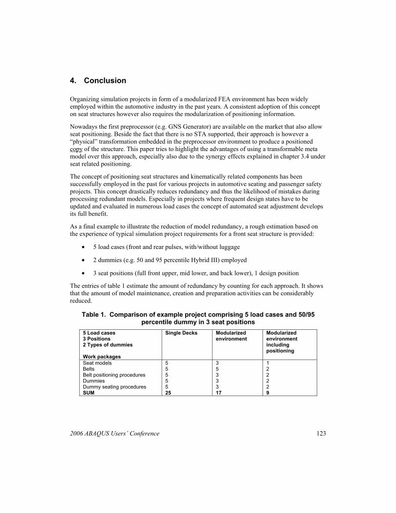
As a final example to illustrate the reduction of model redundancy, a rough estimation based on the experience of typical simulation project requirements for a front seat structure is provided:
• 5 load cases (front and rear pulses, with/without luggage
• 2 dummies (e.g. 50 and 95 percentile Hybrid III) employed
• 3 seat positions (full front upper, mid lower, and back lower), 1 design position
The entries of table 1 estimate the amount of redundancy by counting for each approach. It shows that the amount of model maintenance, creation and preparation activities can be considerably reduced.
Table 1. Comparison of example project comprising 5 load cases and 50/95 percentile dummy in 3 seat positions
5 Load cases 3 Positions 2 Types of dummies Work packages
Single Decks Modularized environment
Modularized environment including positioning
Seat models 5 3 1 Belts 5 5 2 Belt positioning procedures 5 3 2 Dummies 5 3 2 Dummy seating procedures 5 3 2 SUM 25 17 9
124 2006 ABAQUS Users’ Conference
5. References
1. UN Economic Commission for Europe, “UNIFORM PROVISIONS CONCERNING THE APPROVAL OF VEHICLESWITH REGARD TO SAFETY-BELT ANCHORAGES,” Regulation 14, Transport Division, Technology Section, Geneva, Switzerland, 2003.
2. UN Economic Commission for Europe, “VEHICLES EQUIPPED WITH SAFETY-BELTS, RESTRAINT SYSTEMS, CHILD RESTRAINT SYSTEMS AND ISOFIX CHILD RESTRAINT SYSTEMS,” Regulation 16, Transport Division, Technology Section, Geneva, Switzerland, 2005.
3. UN Economic Commission for Europe, “UNIFORM PROVISIONS CONCERNING THE APPROVAL OF VEHICLES WITH REGARD TO THE SEATS, THEIR ANCHORAGES AND ANY HEAD RESTRAINTS,” Regulation 17, Transport Division, Technology Section, Geneva, Switzerland, 2002.