autodesk project photofly
TRANSCRIPT
Getting Started with Photo Scene Editor 2.0 – © Autodesk – May 2011 - Page 1
Autodesk Project Photofly
Getting Started with the Photo Scene Editor 2.0
Last Update: May 2011
Introduction Capturing the as-built reality for purposes, e.g. renovation, energy analysis, add-on
design, is now possible using your standard digital camera, thanks to advanced
computer vision technologies developed by Autodesk made available through
“Project Photofly.”
Project Photofly is a technology preview that automatically converts photographs
shot around an object or of a scene into “Photo Scenes,” which includes a
photorealistic 3D model, utilizing the power of cloud computing. To use the power
of Project Photofly, a standalone application for Windows called the “Photo Scene
Editor” has been developed. This application lets you submit your photographs to
the Project Photofly web service and view the returned Photo Scenes. You can save
your Photo Scenes and export the computed 3D points, cameras, and 3D geometry
in various CAD formats.
This document is the Photo Scene Editor User Guide, which will guide you through
the process of creating Photo Scenes and working with them.
Getting Started with Photo Scene Editor 2.0 – © Autodesk – May 2011 - Page 2
Contents
Terms & Definitions
System Requirements
Installation Instructions
Chapter 1 – Shooting the right images
Chapter 2 – Creation of a Photo Scene
2.1 – Global workflow
2.2 – Creating a Photo Scene – Stage 1 (draft mesh)
2.3 – Creating a Photo Scene – Stage 2 (refined mesh)
2.4 – Checking for wrong cameras
2.5 – Manual Stitch
2.6 – Adding Images
2.7 – Sharing projects
Chapter 3 – Viewing and Navigation in the Photo Scene
3.1 – Selecting the interface layout
3.2 – Viewing the stitching results
3.3 – Navigating in the Photo Scene
3.4 - Free 3D Navigation in the Photo Scene
3.5 – Lock on Camera Mode
Chapter 4 – Edition of the Photo Scene
4.1 – Cleaning the 3D mesh
4.2 – Creating Reference Points
4.3 – Setting a World Coordinate System
4.4 – Setting a Reference Distance
4.5 - Making Measurements
4.6 – Creating Lines and Polylines
Chapter 5 – Export of a Photo Scene
Chapter 6 – Creation of a movie
Annex 1 – Preferences
Annex 2 – Error Messages
1 - Error Messages from the Photo Scene Editor
2 - Error Messages from the Automatic Stitching Engine
Getting Started with Photo Scene Editor 2.0 – © Autodesk – May 2011 - Page 3
Terms & Definitions
Term Definition
Image The Images are the pictures that you shoot around an object or a scene
using your digital camera. They can be in .jpeg or .tif format.
Feature
A feature is a group of pixels in the Image that contains some
remarkable information such as some variation in contrast. There will be many features automatically extracted by computer vision
algorithms in each single Image. Matching corresponding features in
several Images is the basis of the Stitching process.
Stitching
Also called “camera calibration” or “camera registration,” the Stitching process is the process of automatically computing the Photo Scene from
Images. It utilizes a series of computer vision algorithms called the
“Camera Factory Engine,” that runs in the cloud.
Photo Scene
The result of the Stitching process is called a “Photo Scene.” The Photo
Scene includes “Calibrated Cameras,” associated with their undistorted “Background Pictures,” a 3D point cloud called the “Automatic Point
Cloud,” and a photo textured 3D mesh. A global scale and coordinate
system can be set for the Photo Scene.
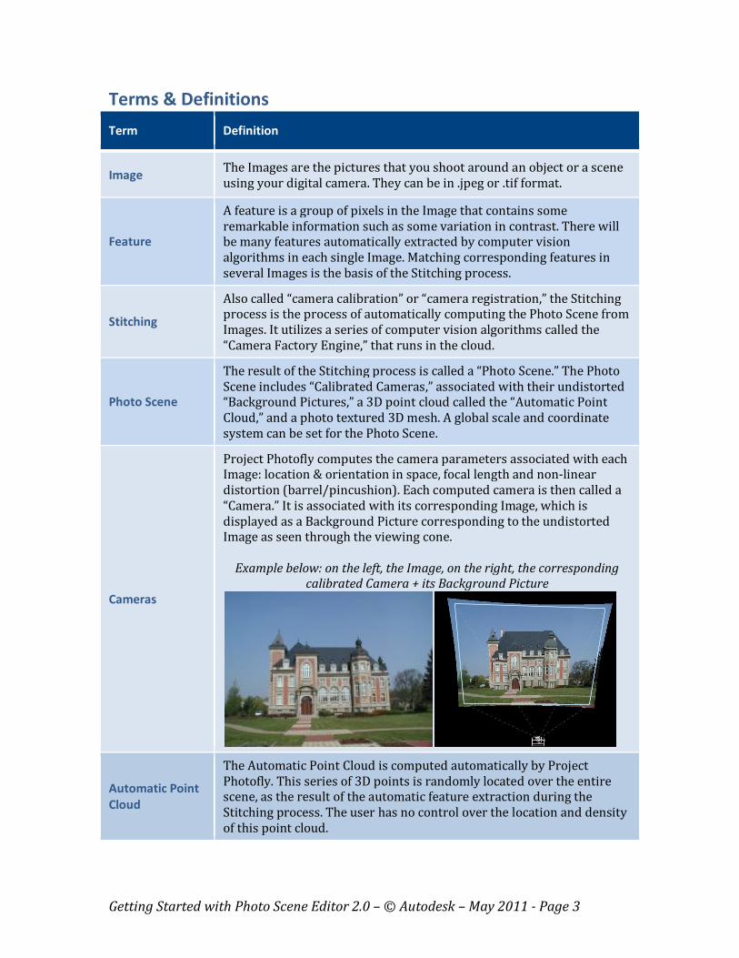
Cameras
Project Photofly computes the camera parameters associated with each Image: location & orientation in space, focal length and non-linear
distortion (barrel/pincushion). Each computed camera is then called a
“Camera.” It is associated with its corresponding Image, which is
displayed as a Background Picture corresponding to the undistorted Image as seen through the viewing cone.
Example below: on the left, the Image, on the right, the corresponding calibrated Camera + its Background Picture
Automatic Point
Cloud
The Automatic Point Cloud is computed automatically by Project
Photofly. This series of 3D points is randomly located over the entire scene, as the result of the automatic feature extraction during the
Stitching process. The user has no control over the location and density
of this point cloud.
Getting Started with Photo Scene Editor 2.0 – © Autodesk – May 2011 - Page 4
Photo Scene
Editor
The Photo Scene Editor is a Windows-based application that lets you
submit your Images to the Project Photofly server, to automatically run
the Stitching process, and to view the Photo Scenes returned by the server. Using the Photo Scene Editor, you can edit the scene, assign a
scale and a coordinate system, add “Reference Points and Lines” (see
below), and export the Photo Scenes to various file formats such as
DWG.
Reference Points
The Automatic Point Cloud may not provide 3D points exactly where
necessary for further snapping or measurement operations. Additional
3D points can then be manually placed by the user, using the Photo
Scene Editor. They are collectively called the “Reference Points.” A semi-automatic process lets you perform this task easily.
Reference Lines
The Photo Scene Editor lets you create lines and polylines that can then be used as references geometry when drawing and designing in 3D
using other Autodesk applications, e.g., AutoCAD.
Manual Stitch
Some Images may not be stitched automatically, or may be stitched
improperly by the automatic engine. In this case, the user can manually
select matching Features between any non-stitched photo and some
other stitched ones, before re-launching the Photo Scene computation process. This process is called Manual Stitch.
Splats
Splats are the local texture maps associated with each 3D point of the
Automatic Point Cloud. They provide a better, more photo-realistic,
visualization of the object or the scene. They cannot be exported in a file for use in another application. You may independently activate the
display of splats and/or 3D points using the toggle tools provided in the
Photo Scene Editor.
3D Mesh
The result of the computation, starting with Photo Scene Editor 2.0, is a 3D mesh, i.e. a 3D model made of triangular polygons. This 3D mesh can
be:
- Draft, if computed automatically right after the stitching
process; - Refined, if computed after the draft one, in a user-selected
resolution. The photo-texturing is also optimized with the
refined mesh.

Getting Started with Photo Scene Editor 2.0 – © Autodesk – May 2011 - Page 5
System Requirements
Operating Systems:
- Microsoft® Windows® XP Service Pack 3 or higher
- Microsoft® Windows® 7
- 32-bit and 64-bit systems
Recommended CPU:
- Intel®Core™2Duo.
Memory:
- 1 GB RAM
Hard Disk:
- 1 GB free hard drive
Graphic card:
- OpenGL compatible Video Card (Recommended OpenGL version 1.3)
- Video Size : 256MB or more Video Memory
Installation Instructions First installation:
1. Click the “Download Now” button on following page:
http://labs.autodesk.com/utilities/photo_scene_editor/.
2. Download the installer “PhotoSceneEditorInstaller.msi.” Click on this file and
follow the instruction to install the Photo Scene Editor.
Updates:
The latest version of the Photo Scene Editor is required for the compatibility with
the Web Service, which is continuously updated with new features. The Photo Scene
Editor will automatically check for updates if you create a Photo Scene. If an update
is required:
1. Click the “Download” button on the following page:
http://labs.autodesk.com/utilities/photo_scene_editor/ .
2. Download the installer “PhotoSceneEditorInstaller.msi.” Click on this file and
follow the instruction to update your Photo Scene Editor.
Important: You will need to update the drivers if you are using one of the following
graphic boards, for a proper use of the Photo Scene Editor.
- NVIDIA GeForce 8600 GT (Update from NVIDIA website)
- NVIDIA GeForce 9800 GT (Update from NVIDIA website)
- Intel® Q35 Express Chipset Family (Update by option in right click)
- Integrated - Intel® Q45/Q43 Express Chipset (Update by option in right click)
Getting Started with Photo Scene Editor 2.0 – © Autodesk – May 2011 - Page 6
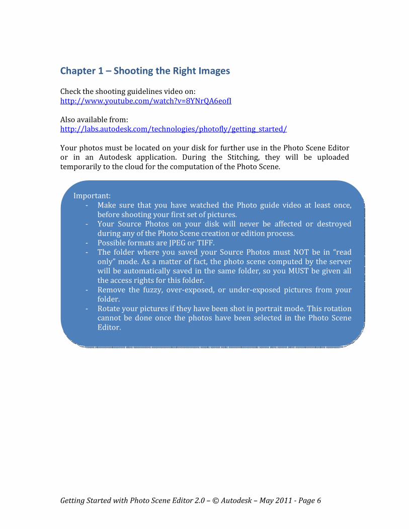
Chapter 1 – Shooting the Right Images
Check the shooting guidelines video on:
http://www.youtube.com/watch?v=8YNrQA6eofI
Also available from:
http://labs.autodesk.com/technologies/photofly/getting_started/
Your photos must be located on your disk for further use in the Photo Scene Editor
or in an Autodesk application. During the Stitching, they will be uploaded
temporarily to the cloud for the computation of the Photo Scene.
Important:
- Make sure that you have watched the Photo guide video at least once,
before shooting your first set of pictures.
- Your Source Photos on your disk will never be affected or destroyed
during any of the Photo Scene creation or edition process.
- Possible formats are JPEG or TIFF.
- The folder where you saved your Source Photos must NOT be in “read
only” mode. As a matter of fact, the photo scene computed by the server
will be automatically saved in the same folder, so you MUST be given all
the access rights for this folder.
- Remove the fuzzy, over-exposed, or under-exposed pictures from your
folder.
- Rotate your pictures if they have been shot in portrait mode. This rotation
cannot be done once the photos have been selected in the Photo Scene
Editor.
Getting Started with Photo Scene Editor 2.0 – © Autodesk – May 2011 - Page 7
Chapter 2 – Creation of a Photo Scene
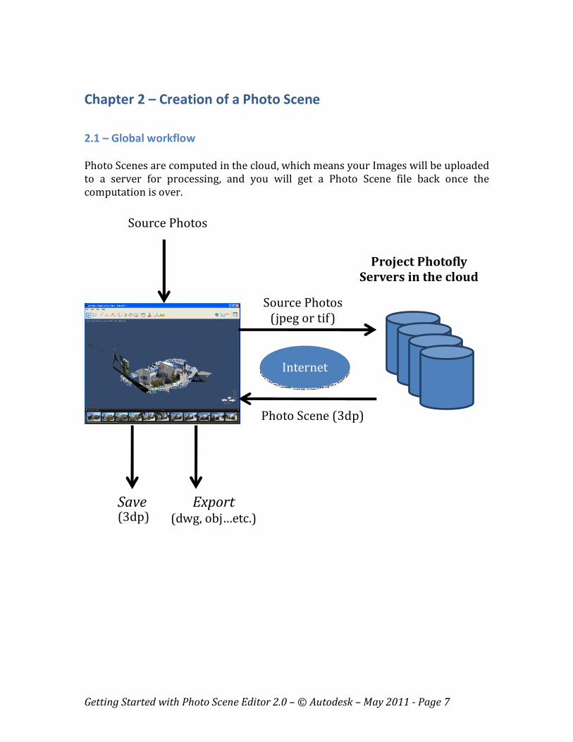
2.1 – Global workflow
Photo Scenes are computed in the cloud, which means your Images will be uploaded
to a server for processing, and you will get a Photo Scene file back once the
computation is over.
Internet
Source Photos
(jpeg or tif)
Photo Scene (3dp)
Project Photofly
Servers in the cloud
Source Photos
Save
(3dp)
Export
(dwg, obj…etc.)
Getting Started with Photo Scene Editor 2.0 – © Autodesk – May 2011 - Page 8
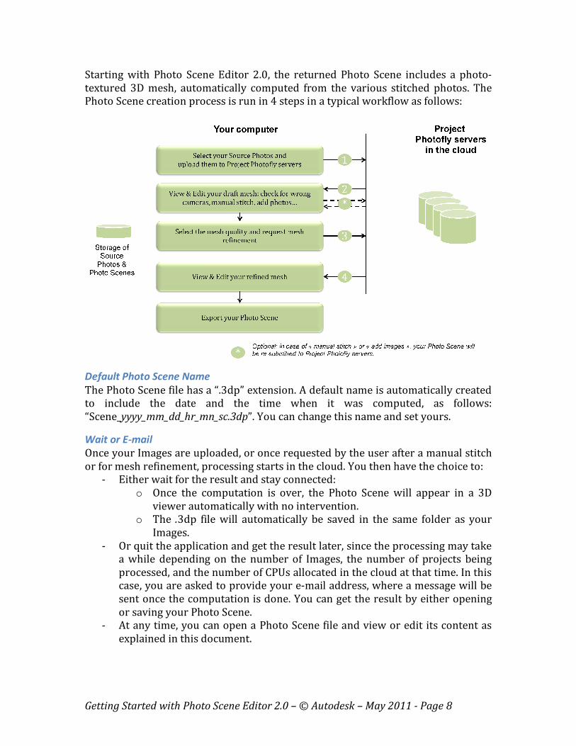
Starting with Photo Scene Editor 2.0, the returned Photo Scene includes a photo-
textured 3D mesh, automatically computed from the various stitched photos. The
Photo Scene creation process is run in 4 steps in a typical workflow as follows:
Default Photo Scene Name
The Photo Scene file has a “.3dp” extension. A default name is automatically created
to include the date and the time when it was computed, as follows:
“Scene_yyyy_mm_dd_hr_mn_sc.3dp”. You can change this name and set yours.
Wait or E-mail
Once your Images are uploaded, or once requested by the user after a manual stitch
or for mesh refinement, processing starts in the cloud. You then have the choice to:
- Either wait for the result and stay connected:
o Once the computation is over, the Photo Scene will appear in a 3D
viewer automatically with no intervention.
o The .3dp file will automatically be saved in the same folder as your
Images.
- Or quit the application and get the result later, since the processing may take
a while depending on the number of Images, the number of projects being
processed, and the number of CPUs allocated in the cloud at that time. In this
case, you are asked to provide your e-mail address, where a message will be
sent once the computation is done. You can get the result by either opening
or saving your Photo Scene.
- At any time, you can open a Photo Scene file and view or edit its content as
explained in this document.

Getting Started with Photo Scene Editor 2.0 – © Autodesk – May 2011 - Page 9
2.2 – Creating a Photo Scene – Stage 1 (draft mesh)
- Run “PhotoSceneEditor.exe” to start the Photo Scene Editor wizard. If you are
connected to the Internet, the following window will pop-up:
- If you are not connected to the Internet, or if you are behind a proxy server,
when starting your Photo Scene Editor, the following error message will
appear before the pop-up window above appears:

Getting Started with Photo Scene Editor 2.0 – © Autodesk – May 2011 - Page 10
o If you click on “Work Offline,” the following message will appear:
Click on “OK” to continue using your Photo Scene Editor to open, view
and edit Photo Scenes in this case. The creation of Photo Scenes will
not be possible in this case. See paragraph 2.4 below “Opening a Photo
Scene.”
o Clicking on “Edit Proxy Settings” will pop-up the “Connection” setting
tab of the Photo Scene Editor Preferences window. Check the
instructions in the Annex 1 – Preferences – Connection.
T
h folder where you saved your Source Photos must NOT be in “read only”
Important:
- Your computer MUST be at the right date and time, in your right time zone.
Otherwise, the connection with the Project Photofly servers (which may well
be in another time zone than yours) will NOT respond correctly.

Getting Started with Photo Scene Editor 2.0 – © Autodesk – May 2011 - Page 11
- Click on “Create Photo Scene From Your Images” to start the process. This
will open the following selection window.
- Browse and select your photos. Click on “Open” when finished. This will open
the following window:
Getting Started with Photo Scene Editor 2.0 – © Autodesk – May 2011 - Page 12
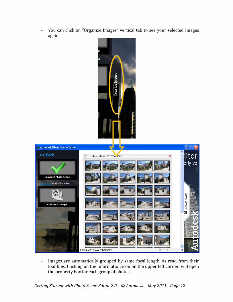
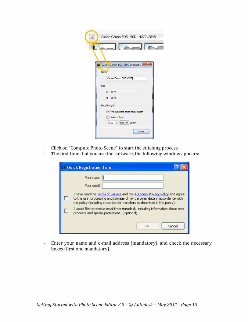
- You can click on “Organize Images” vertical tab to see your selected Images
again.
- Images are automatically grouped by same focal length, as read from their
Exif files. Clicking on the information icon on the upper left corner, will open
the property box for each group of photos.
Getting Started with Photo Scene Editor 2.0 – © Autodesk – May 2011 - Page 13
- Click on “Compute Photo Scene” to start the stitching process.
- The first time that you use the software, the following window appears:
- Enter your name and e-mail address (mandatory), and check the necessary
boxes (first one mandatory).
Getting Started with Photo Scene Editor 2.0 – © Autodesk – May 2011 - Page 14
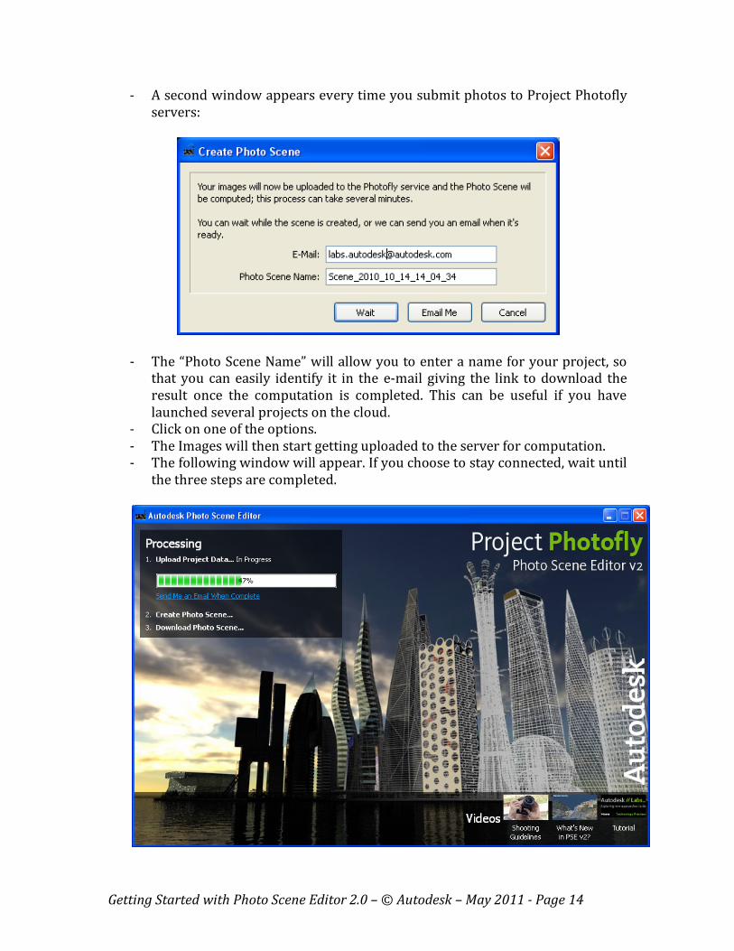
- A second window appears every time you submit photos to Project Photofly
servers:
- The “Photo Scene Name” will allow you to enter a name for your project, so
that you can easily identify it in the e-mail giving the link to download the
result once the computation is completed. This can be useful if you have
launched several projects on the cloud.
- Click on one of the options.
- The Images will then start getting uploaded to the server for computation.
- The following window will appear. If you choose to stay connected, wait until
the three steps are completed.
Getting Started with Photo Scene Editor 2.0 – © Autodesk – May 2011 - Page 15
- Note that the Photo Scene creation process may start on the first uploaded
pictures. So you may see the second progress bar start before the upload is
completed.
- At any time during the process, you can click on “Send Me an Email When
Complete” if you select not to wait until the upload (step 1) and/or the
computation (step 2) is over.
- If an error occurs during the automatic stitching process, you may receive
one the error messages listed in Annex 2. You will then need to proceed
according to the instructions given in such messages.
Receiving an e-mail once the computation is finished
- Once the computation is over, you will receive the following e-mail from
Autodesk Labs:
“Your Photo Scene has been created successfully. Here is the link to
download your Photo Scene: …..”
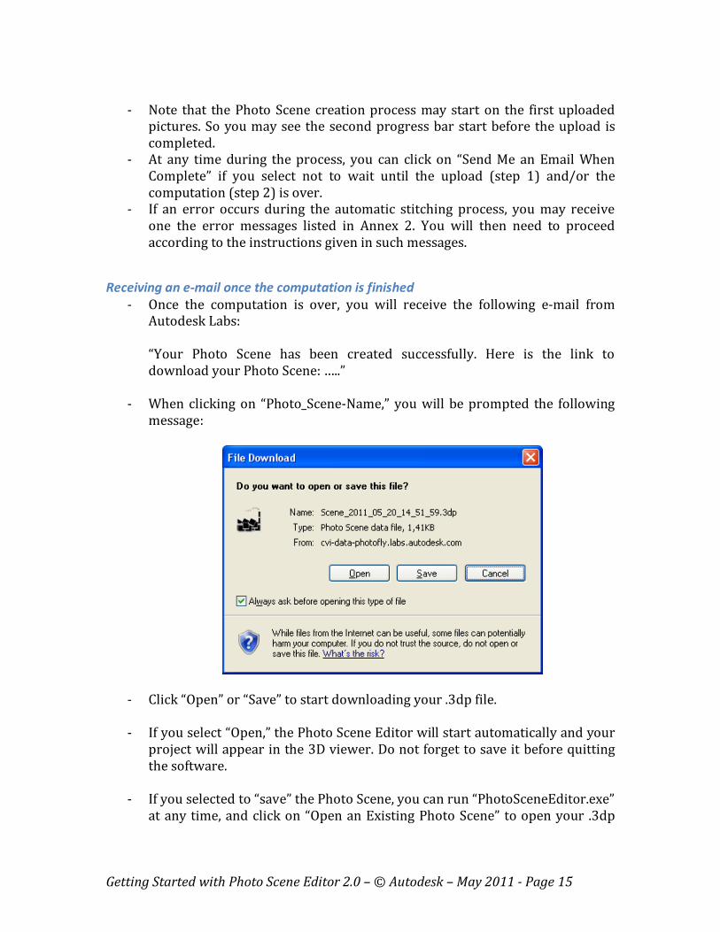
- When clicking on “Photo_Scene-Name,” you will be prompted the following
message:
- Click “Open” or “Save” to start downloading your .3dp file.
- If you select “Open,” the Photo Scene Editor will start automatically and your
project will appear in the 3D viewer. Do not forget to save it before quitting
the software.
- If you selected to “save” the Photo Scene, you can run “PhotoSceneEditor.exe”
at any time, and click on “Open an Existing Photo Scene” to open your .3dp
Getting Started with Photo Scene Editor 2.0 – © Autodesk – May 2011 - Page 16
file. You can also directly access your “Recent Files” by clicking on one of the
thumbnails on the lower right of the window.
- The Photo Scene will automatically appear in the 3D viewer.
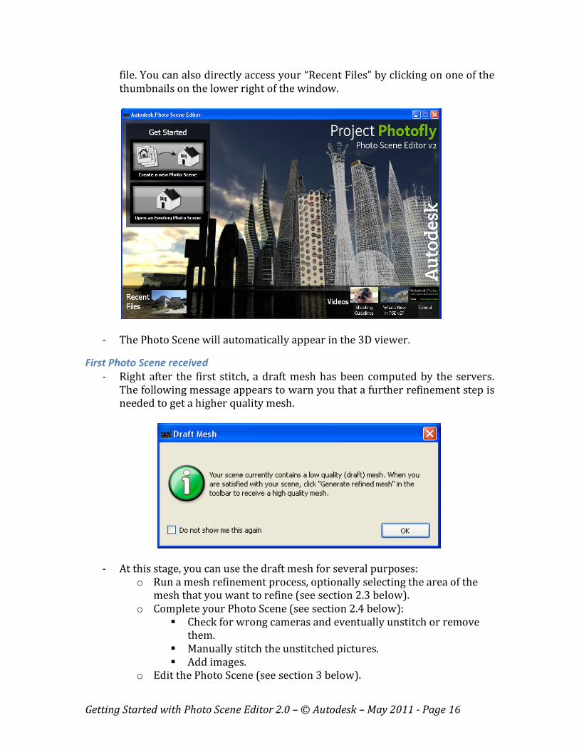
First Photo Scene received
- Right after the first stitch, a draft mesh has been computed by the servers.
The following message appears to warn you that a further refinement step is
needed to get a higher quality mesh.
- At this stage, you can use the draft mesh for several purposes:
o Run a mesh refinement process, optionally selecting the area of the
mesh that you want to refine (see section 2.3 below).
o Complete your Photo Scene (see section 2.4 below):
� Check for wrong cameras and eventually unstitch or remove
them.
� Manually stitch the unstitched pictures.
� Add images.
o Edit the Photo Scene (see section 3 below).
Getting Started with Photo Scene Editor 2.0 – © Autodesk – May 2011 - Page 17
o Export the draft mesh as is, in one the 3D formats (see section 4
below).
o Export the file as a RZI file, for photo-modeling inside AutoCAD.
2.3 – Creating a Photo Scene – Stage 2 (refined mesh)
Request for a mesh refinement
- Before requesting a mesh refinement, you can define the area of the mesh
that you want: check “Section 3 – Editing the Photo Scene.”
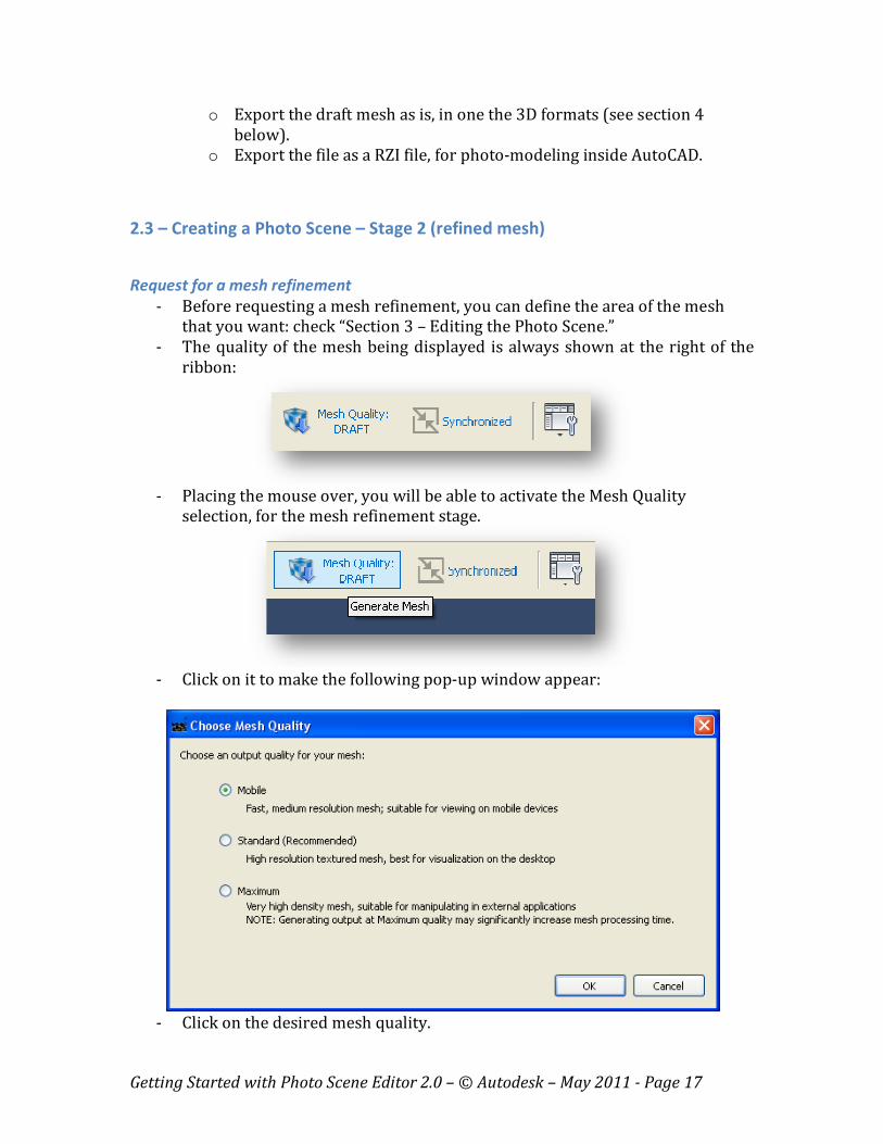
- The quality of the mesh being displayed is always shown at the right of the
ribbon:
- Placing the mouse over, you will be able to activate the Mesh Quality
selection, for the mesh refinement stage.
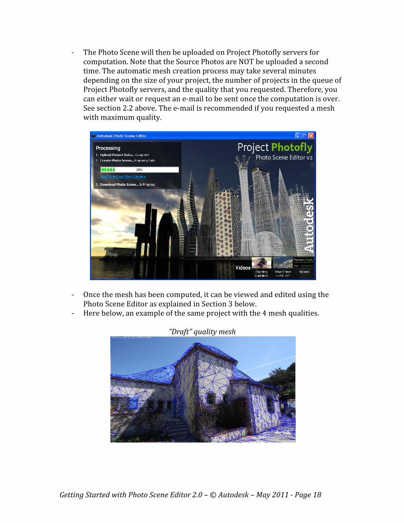
- Click on it to make the following pop-up window appear:
- Click on the desired mesh quality.
Getting Started with Photo Scene Editor 2.0 – © Autodesk – May 2011 - Page 18
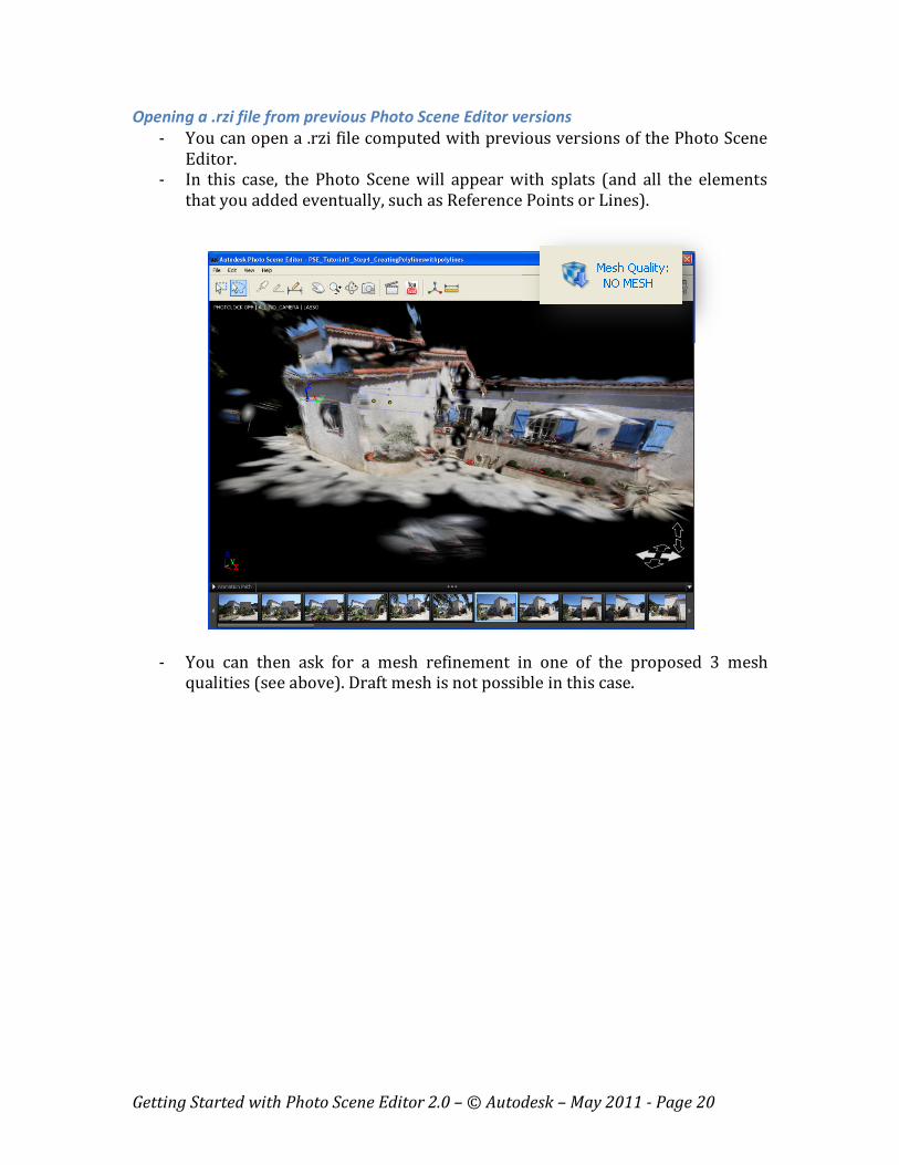
- The Photo Scene will then be uploaded on Project Photofly servers for
computation. Note that the Source Photos are NOT be uploaded a second
time. The automatic mesh creation process may take several minutes
depending on the size of your project, the number of projects in the queue of
Project Photofly servers, and the quality that you requested. Therefore, you
can either wait or request an e-mail to be sent once the computation is over.
See section 2.2 above. The e-mail is recommended if you requested a mesh
with maximum quality.
- Once the mesh has been computed, it can be viewed and edited using the
Photo Scene Editor as explained in Section 3 below.
- Here below, an example of the same project with the 4 mesh qualities.
“Draft” quality mesh

Getting Started with Photo Scene Editor 2.0 – © Autodesk – May 2011 - Page 19
“Mobile” quality mesh
“Standard” quality mesh
“Maximum” quality mesh
Getting Started with Photo Scene Editor 2.0 – © Autodesk – May 2011 - Page 20
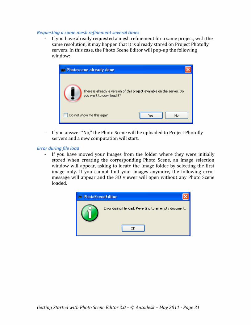
Opening a .rzi file from previous Photo Scene Editor versions
- You can open a .rzi file computed with previous versions of the Photo Scene
Editor.
- In this case, the Photo Scene will appear with splats (and all the elements
that you added eventually, such as Reference Points or Lines).
- You can then ask for a mesh refinement in one of the proposed 3 mesh
qualities (see above). Draft mesh is not possible in this case.
Getting Started with Photo Scene Editor 2.0 – © Autodesk – May 2011 - Page 21
Requesting a same mesh refinement several times
- If you have already requested a mesh refinement for a same project, with the
same resolution, it may happen that it is already stored on Project Photofly
servers. In this case, the Photo Scene Editor will pop-up the following
window:
- If you answer “No,” the Photo Scene will be uploaded to Project Photofly
servers and a new computation will start.
Error during file load
- If you have moved your Images from the folder where they were initially
stored when creating the corresponding Photo Scene, an image selection
window will appear, asking to locate the Image folder by selecting the first
image only. If you cannot find your images anymore, the following error
message will appear and the 3D viewer will open without any Photo Scene
loaded.

Getting Started with Photo Scene Editor 2.0 – © Autodesk – May 2011 - Page 22
2.4 – Checking for wrong cameras
Sometimes, the Project Photofly automatic engine is not 100% successful.
- Case 1: The automatic engine did not provide 100% stitching success on all
your Images. Photos that were not stitched automatically are viewed in the
thumbnail as darker pictures and with a yellow warning as shown below:
In most cases, this is due to a lack of visual continuity between adjacent
pictures. Check the Shooting guidelines in Chapter 1 for more information.
You can manually connect these photos with the already stitched ones,
through a “Manual Stitch” (see section 2.5 below).
- Case 2: In some cases, the automatic engine will compute wrong camera
information. This may occur when your pictures contain so many repetitive
patterns that even human eyes can hardly make a difference. For example,
the many sides of a building may all look alike, and the engine may well place
some of your photos on the wrong side of the building. In this case 2, you will
need to unstitch this (these) photo(s) and manually stitch it (them) again.
Checking for wrong cameras – Method 1
One way to check if this case 2 happened is to look at the computed camera path,
that you can compare to your real sequence of shooting (if you took the pictures of
course). In the example below, the 4 cameras in red have been stitched improperly,
which is visible by the camera path, which should have been continuous in this case.
Getting Started with Photo Scene Editor 2.0 – © Autodesk – May 2011 - Page 23
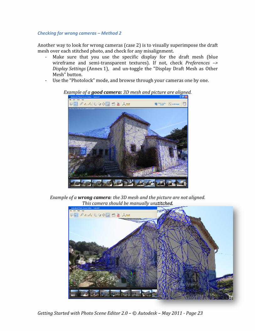
Checking for wrong cameras – Method 2
Another way to look for wrong cameras (case 2) is to visually superimpose the draft
mesh over each stitched photo, and check for any misalignment.
- Make sure that you use the specific display for the draft mesh (blue
wireframe and semi-transparent textures). If not, check Preferences –>
Display Settings (Annex 1), and un-toggle the “Display Draft Mesh as Other
Mesh” button.
- Use the “Photolock” mode, and browse through your cameras one by one.
Example of a good camera: 3D mesh and picture are aligned.
Example of a wrong camera: the 3D mesh and the picture are not aligned.
This camera should be manually unstitched.
Getting Started with Photo Scene Editor 2.0 – © Autodesk – May 2011 - Page 24
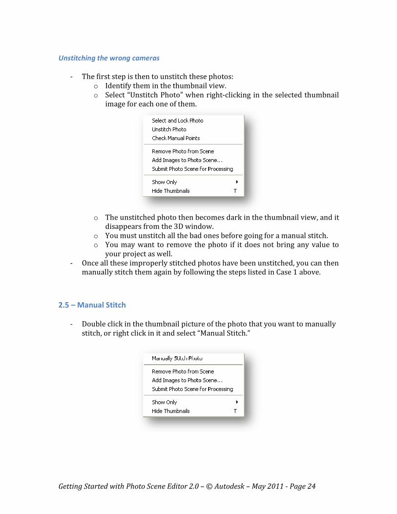
Unstitching the wrong cameras
- The first step is then to unstitch these photos:
o Identify them in the thumbnail view.
o Select “Unstitch Photo” when right-clicking in the selected thumbnail
image for each one of them.
o The unstitched photo then becomes dark in the thumbnail view, and it
disappears from the 3D window.
o You must unstitch all the bad ones before going for a manual stitch.
o You may want to remove the photo if it does not bring any value to
your project as well.
- Once all these improperly stitched photos have been unstitched, you can then
manually stitch them again by following the steps listed in Case 1 above.
2.5 – Manual Stitch
- Double click in the thumbnail picture of the photo that you want to manually
stitch, or right click in it and select “Manual Stitch.”
Getting Started with Photo Scene Editor 2.0 – © Autodesk – May 2011 - Page 25
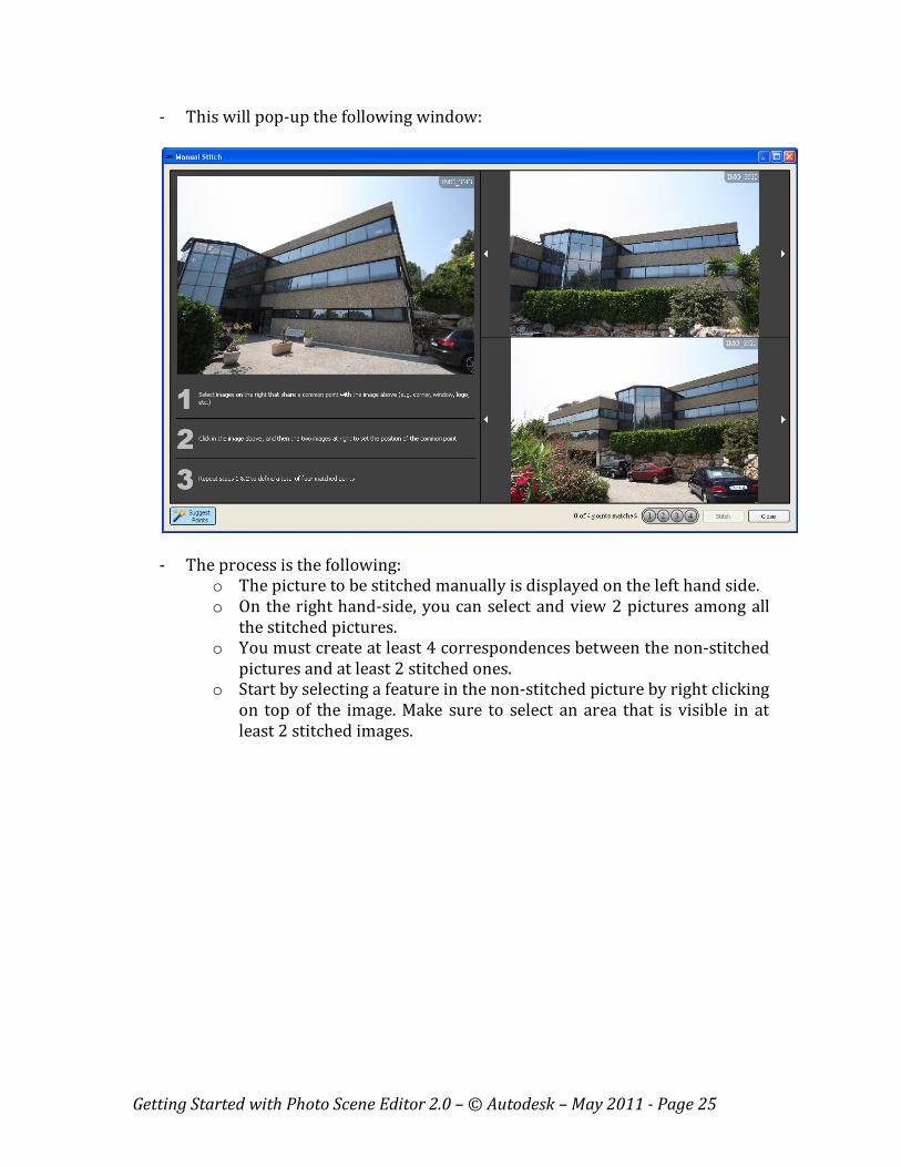
- This will pop-up the following window:
- The process is the following:
o The picture to be stitched manually is displayed on the left hand side.
o On the right hand-side, you can select and view 2 pictures among all
the stitched pictures.
o You must create at least 4 correspondences between the non-stitched
pictures and at least 2 stitched ones.
o Start by selecting a feature in the non-stitched picture by right clicking
on top of the image. Make sure to select an area that is visible in at
least 2 stitched images.
Getting Started with Photo Scene Editor 2.0 – © Autodesk – May 2011 - Page 26
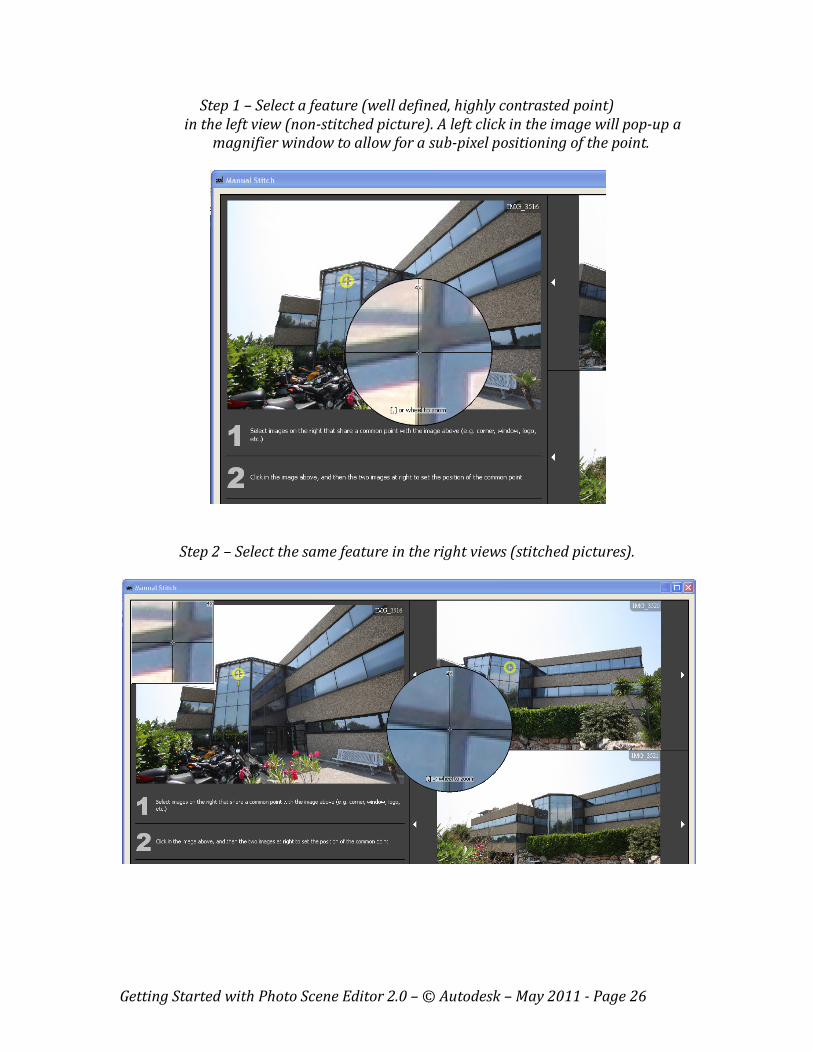
Step 1 – Select a feature (well defined, highly contrasted point)
in the left view (non-stitched picture). A left click in the image will pop-up a
magnifier window to allow for a sub-pixel positioning of the point.
Step 2 – Select the same feature in the right views (stitched pictures).

Getting Started with Photo Scene Editor 2.0 – © Autodesk – May 2011 - Page 27
Step 3 – If the “Suggest Points” button is set at bottom left of the window, the software
will automatically propose a matching feature in the third view as below. Proposed
features are marked with a yellow square.
Step 4 – In all cases (proposed feature or not), you must click at the right location to
complete the manual matching process on the third view as well.
Getting Started with Photo Scene Editor 2.0 – © Autodesk – May 2011 - Page 28
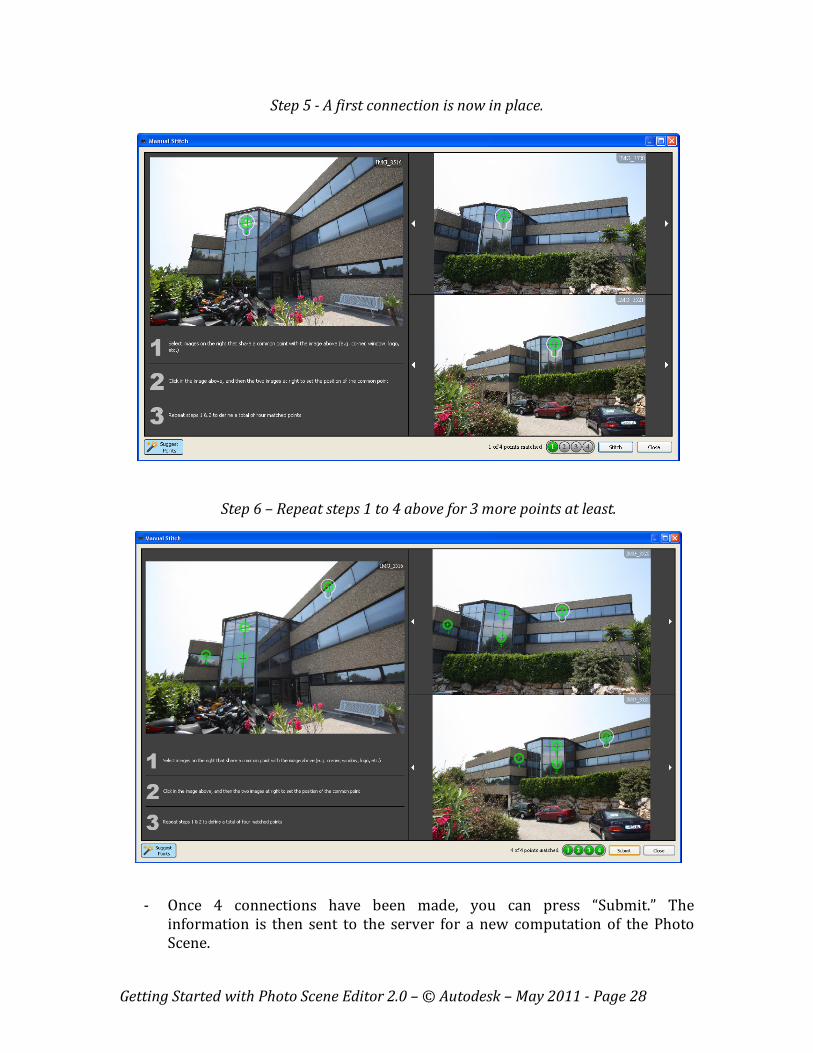
Step 5 - A first connection is now in place.
Step 6 – Repeat steps 1 to 4 above for 3 more points at least.
- Once 4 connections have been made, you can press “Submit.” The
information is then sent to the server for a new computation of the Photo
Scene.
Getting Started with Photo Scene Editor 2.0 – © Autodesk – May 2011 - Page 29
- As explained in section 2.2, you may wait for the result, or “Quit and Receive
the Photo Scene Later.”
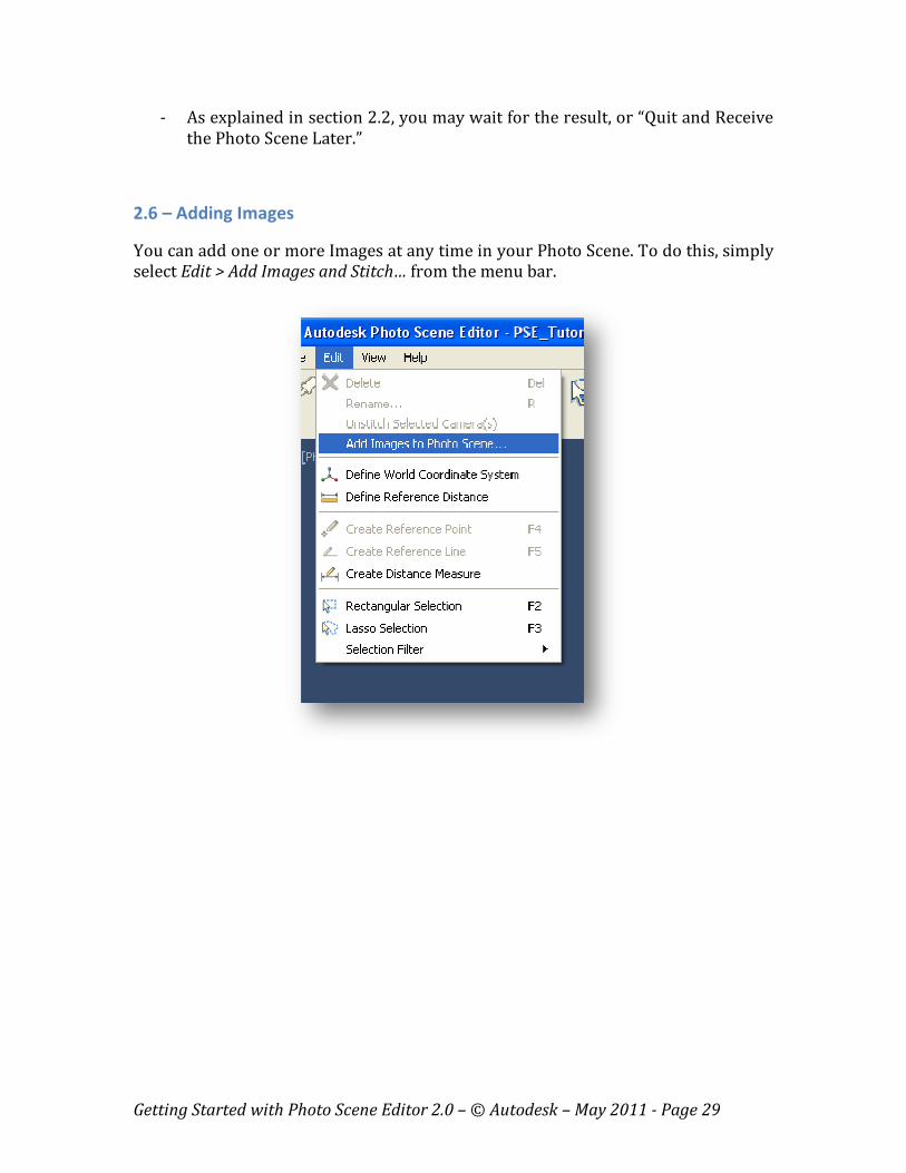
2.6 – Adding Images
You can add one or more Images at any time in your Photo Scene. To do this, simply
select Edit > Add Images and Stitch… from the menu bar.
Getting Started with Photo Scene Editor 2.0 – © Autodesk – May 2011 - Page 30
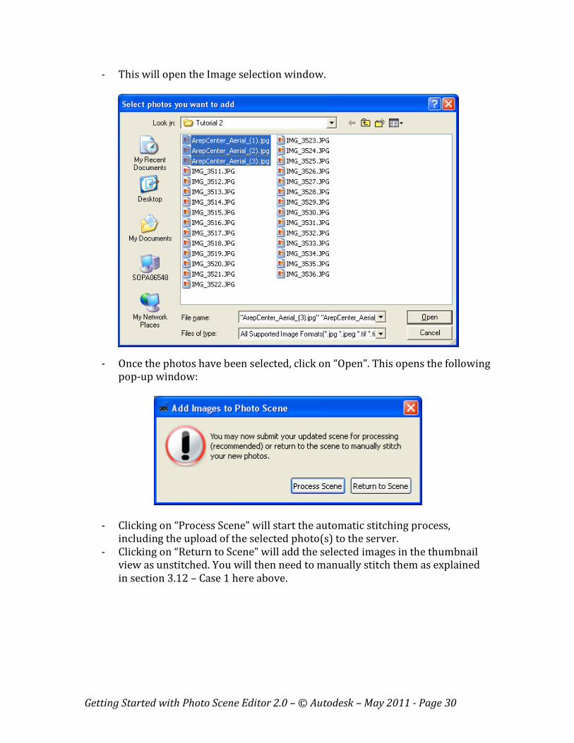
- This will open the Image selection window.
- Once the photos have been selected, click on “Open”. This opens the following
pop-up window:
- Clicking on “Process Scene” will start the automatic stitching process,
including the upload of the selected photo(s) to the server.
- Clicking on “Return to Scene” will add the selected images in the thumbnail
view as unstitched. You will then need to manually stitch them as explained
in section 3.12 – Case 1 here above.
Getting Started with Photo Scene Editor 2.0 – © Autodesk – May 2011 - Page 31
2.7 – Sharing projects
You can easily share your projects with others by simply sending your 3dp file as an
attachment in an e-mail. The person receiving this 3dp file will need to install the
Photo Scene Editor to open it.
The 3dp file includes some Photo Scene data and references others on your disk
and/or the Project Photofly servers:
- Data included in the 3dp file:
o Camera information
o Reference Points, Lines, measurements, scale, WCS, if added by the
user
o Manual stitch data
- Data NOT included in the 3dp file, but referenced by it:
o Source Photos
o 3D mesh (draft or any other density)
o Points Clouds
When the person will receive your 3dp file, the Photo Scene Editor will look for the
corresponding referenced data on Project Photofly servers. Note that this may take
some time to download all this data since images and mesh can be heavy.
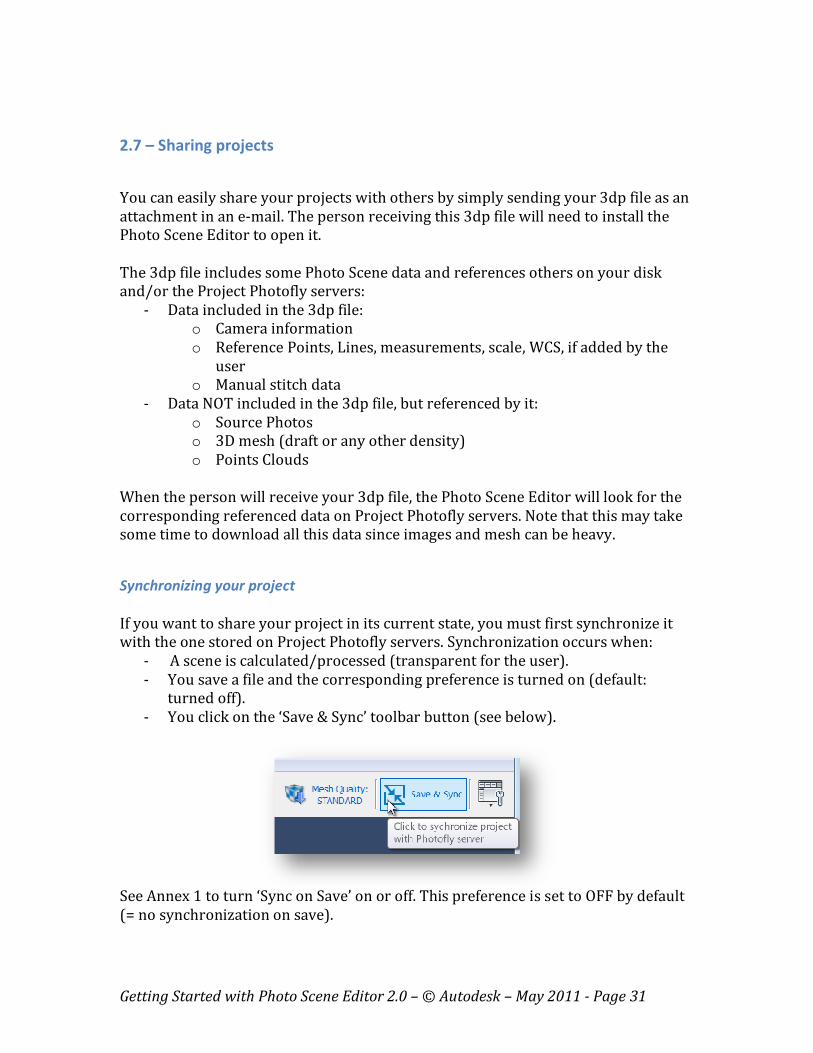
Synchronizing your project
If you want to share your project in its current state, you must first synchronize it
with the one stored on Project Photofly servers. Synchronization occurs when:
- A scene is calculated/processed (transparent for the user).
- You save a file and the corresponding preference is turned on (default:
turned off).
- You click on the ‘Save & Sync’ toolbar button (see below).
See Annex 1 to turn ‘Sync on Save’ on or off. This preference is set to OFF by default
(= no synchronization on save).
Getting Started with Photo Scene Editor 2.0 – © Autodesk – May 2011 - Page 32
Chapter 3 – Viewing and Navigation in the Photo Scene
3.1 – Selecting the interface layout
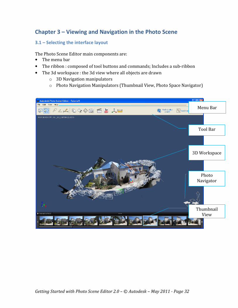
The Photo Scene Editor main components are:
• The menu bar
• The ribbon : composed of tool buttons and commands; Includes a sub-ribbon
• The 3d workspace : the 3d view where all objects are drawn
o 3D Navigation manipulators
o Photo Navigation Manipulators (Thumbnail View, Photo Space Navigator)
Tool Bar
Thumbnail
View
Photo
Navigator
3D Workspace
Menu Bar
Getting Started with Photo Scene Editor 2.0 – © Autodesk – May 2011 - Page 33
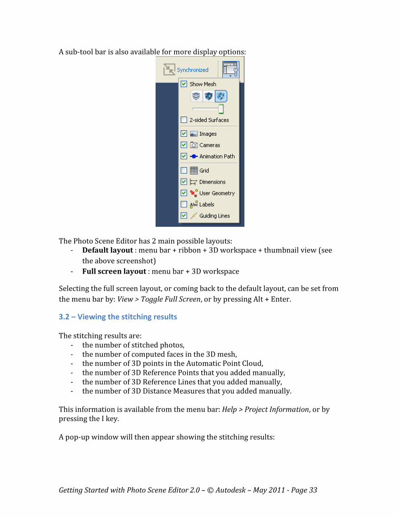
A sub-tool bar is also available for more display options:
The Photo Scene Editor has 2 main possible layouts:
- Default layout : menu bar + ribbon + 3D workspace + thumbnail view (see
the above screenshot)
- Full screen layout : menu bar + 3D workspace
Selecting the full screen layout, or coming back to the default layout, can be set from
the menu bar by: View > Toggle Full Screen, or by pressing Alt + Enter.
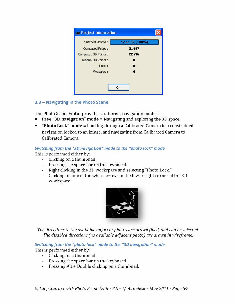
3.2 – Viewing the stitching results
The stitching results are:
- the number of stitched photos,
- the number of computed faces in the 3D mesh,
- the number of 3D points in the Automatic Point Cloud,
- the number of 3D Reference Points that you added manually,
- the number of 3D Reference Lines that you added manually,
- the number of 3D Distance Measures that you added manually.
This information is available from the menu bar: Help > Project Information, or by
pressing the I key.
A pop-up window will then appear showing the stitching results:
Getting Started with Photo Scene Editor 2.0 – © Autodesk – May 2011 - Page 34
3.3 – Navigating in the Photo Scene
The Photo Scene Editor provides 2 different navigation modes:
• Free “3D navigation” mode = Navigating and exploring the 3D space.
• “Photo Lock” mode = Looking through a Calibrated Camera in a constrained
navigation locked to an image, and navigating from Calibrated Camera to
Calibrated Camera.
Switching from the “3D navigation” mode to the “photo lock” mode
This is performed either by:
- Clicking on a thumbnail.
- Pressing the space bar on the keyboard.
- Right clicking in the 3D workspace and selecting “Photo Lock.”
- Clicking on one of the white arrows in the lower right corner of the 3D
workspace:
The directions to the available adjacent photos are drawn filled, and can be selected.
The disabled directions (no available adjacent photo) are drawn in wireframe.
Switching from the “photo lock” mode to the “3D navigation” mode
This is performed either by:
- Clicking on a thumbnail.
- Pressing the space bar on the keyboard.
- Pressing Alt + Double clicking on a thumbnail.
Getting Started with Photo Scene Editor 2.0 – © Autodesk – May 2011 - Page 35
Switching from one photo to the next in the “photo lock” mode
This is performed either by:
- Clicking on a thumbnail.
- Pressing Alt + Left or Right keyboard arrow.
- Orbiting by pressing Alt + Right click in the 3D workspace: this mode will
temporarily use a 3D camera motion to move through the various photos.
The lock on the nearest camera will happen when releasing the right click. To
get this behavior, make sure that “Lock during Photo Orbit” is set in the
Preferences -> General Settings (see Annex 1).
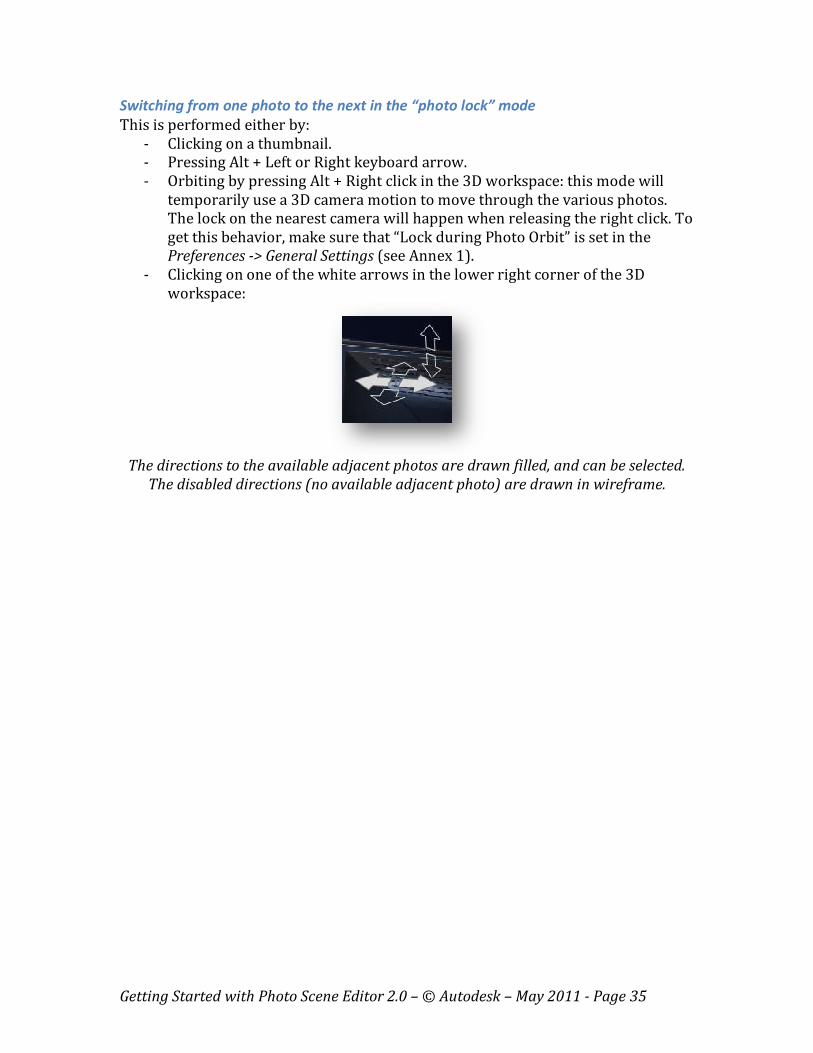
- Clicking on one of the white arrows in the lower right corner of the 3D
workspace:
The directions to the available adjacent photos are drawn filled, and can be selected.
The disabled directions (no available adjacent photo) are drawn in wireframe.
Getting Started with Photo Scene Editor 2.0 – © Autodesk – May 2011 - Page 36
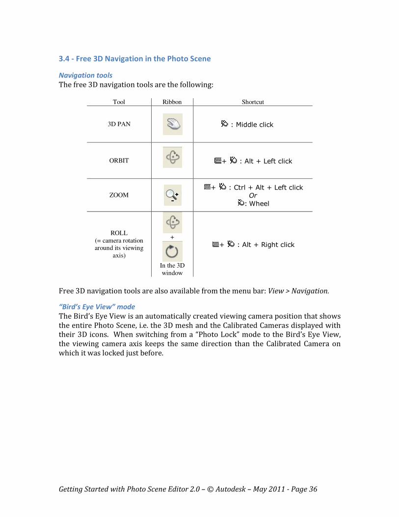
3.4 - Free 3D Navigation in the Photo Scene
Navigation tools
The free 3D navigation tools are the following:
Tool Ribbon Shortcut
3D PAN
: Middle click
ORBIT
+ : Alt + Left click
ZOOM
+ : Ctrl + Alt + Left click
Or
: Wheel
ROLL
(= camera rotation around its viewing
axis)
+
In the 3D
window
+ : Alt + Right click
Free 3D navigation tools are also available from the menu bar: View > Navigation.
“Bird’s Eye View” mode
The Bird’s Eye View is an automatically created viewing camera position that shows
the entire Photo Scene, i.e. the 3D mesh and the Calibrated Cameras displayed with
their 3D icons. When switching from a “Photo Lock” mode to the Bird’s Eye View,
the viewing camera axis keeps the same direction than the Calibrated Camera on
which it was locked just before.
Getting Started with Photo Scene Editor 2.0 – © Autodesk – May 2011 - Page 37
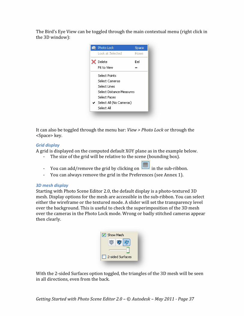
The Bird’s Eye View can be toggled through the main contextual menu (right click in
the 3D window):
It can also be toggled through the menu bar: View > Photo Lock or through the
<Space> key.
Grid display
A grid is displayed on the computed default XOY plane as in the example below.
- The size of the grid will be relative to the scene (bounding box).
- You can add/remove the grid by clicking on in the sub-ribbon.
- You can always remove the grid in the Preferences (see Annex 1).
3D mesh display
Starting with Photo Scene Editor 2.0, the default display is a photo-textured 3D
mesh. Display options for the mesh are accessible in the sub-ribbon. You can select
either the wireframe or the textured mode. A slider will set the transparency level
over the background. This is useful to check the superimposition of the 3D mesh
over the cameras in the Photo Lock mode. Wrong or badly stitched cameras appear
then clearly.
With the 2-sided Surfaces option toggled, the triangles of the 3D mesh will be seen
in all directions, even from the back.
Getting Started with Photo Scene Editor 2.0 – © Autodesk – May 2011 - Page 38
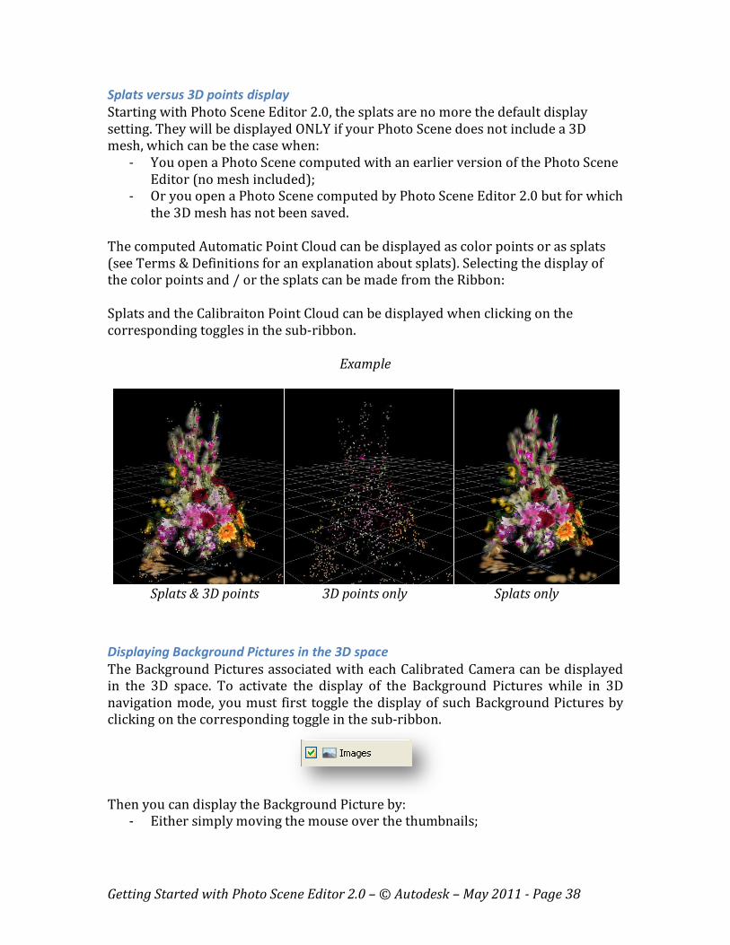
Splats versus 3D points display
Starting with Photo Scene Editor 2.0, the splats are no more the default display
setting. They will be displayed ONLY if your Photo Scene does not include a 3D
mesh, which can be the case when:
- You open a Photo Scene computed with an earlier version of the Photo Scene
Editor (no mesh included);
- Or you open a Photo Scene computed by Photo Scene Editor 2.0 but for which
the 3D mesh has not been saved.
The computed Automatic Point Cloud can be displayed as color points or as splats
(see Terms & Definitions for an explanation about splats). Selecting the display of
the color points and / or the splats can be made from the Ribbon:
Splats and the Calibraiton Point Cloud can be displayed when clicking on the
corresponding toggles in the sub-ribbon.
Example
Splats & 3D points 3D points only Splats only
Displaying Background Pictures in the 3D space
The Background Pictures associated with each Calibrated Camera can be displayed
in the 3D space. To activate the display of the Background Pictures while in 3D
navigation mode, you must first toggle the display of such Background Pictures by
clicking on the corresponding toggle in the sub-ribbon.
Then you can display the Background Picture by:
- Either simply moving the mouse over the thumbnails;
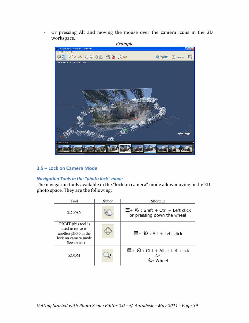
Getting Started with Photo Scene Editor 2.0 – © Autodesk – May 2011 - Page 39
- Or pressing Alt and moving the mouse over the camera icons in the 3D
workspace.
Example
3.5 – Lock on Camera Mode
Navigation Tools in the “photo lock” mode
The navigation tools available in the “lock on camera” mode allow moving in the 2D
photo space. They are the following:
Tool Ribbon Shortcut
2D PAN
+ : Shift + Ctrl + Left click or pressing down the wheel
ORBIT (this tool is
used to move to
another photo in the
lock on camera mode
– See above)
+ : Alt + Left click
ZOOM
+ : Ctrl + Alt + Left click Or
: Wheel
Getting Started with Photo Scene Editor 2.0 – © Autodesk – May 2011 - Page 40
Chapter 4 – Edition of the Photo Scene
4.1 – Cleaning the 3D mesh
At any stage in the process, it might be useful to clean the 3D mesh, either for a
better viewing experience, or to select a specific area of the draft mesh before
requesting a mesh refinement.
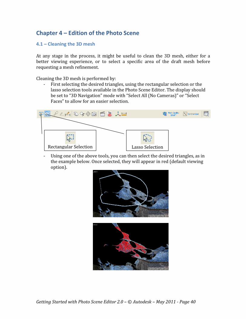
Cleaning the 3D mesh is performed by:
- First selecting the desired triangles, using the rectangular selection or the
lasso selection tools available in the Photo Scene Editor. The display should
be set to “3D Navigation” mode with “Select All (No Cameras)” or “Select
Faces” to allow for an easier selection.
- Using one of the above tools, you can then select the desired triangles, as in
the example below. Once selected, they will appear in red (default viewing
option).
Rectangular Selection
Lasso Selection
Getting Started with Photo Scene Editor 2.0 – © Autodesk – May 2011 - Page 41
- You can then click on the Delete button of the tool bar to delete these
triangles. The delete action can also be performed from the menu bar: Edit >
Delete, or by right clicking in the 3D workspace and selecting “Delete.”
4.2 – Creating Reference Points
Why Reference points?
You may need to create 3D points at locations of interest, for various purposes:
- Setting the World Coordinate System (WCS): the WCS requires a well-located
3D point that will become the origin, and at least 2 pairs of 3D points (the
origin may be one of these points) that will define the X, the Y or the Z axis.
- Setting the scale of the Photo Scene: the scale will be set by assigning a
known distance between two 3D points where the distance indicates real-
world measurements.
- Creating measurements: measurements will be defined between two 3D
points, or between one 3D point and along one of the WCS axis.
- Creating lines and polylines representing edges of the scene.
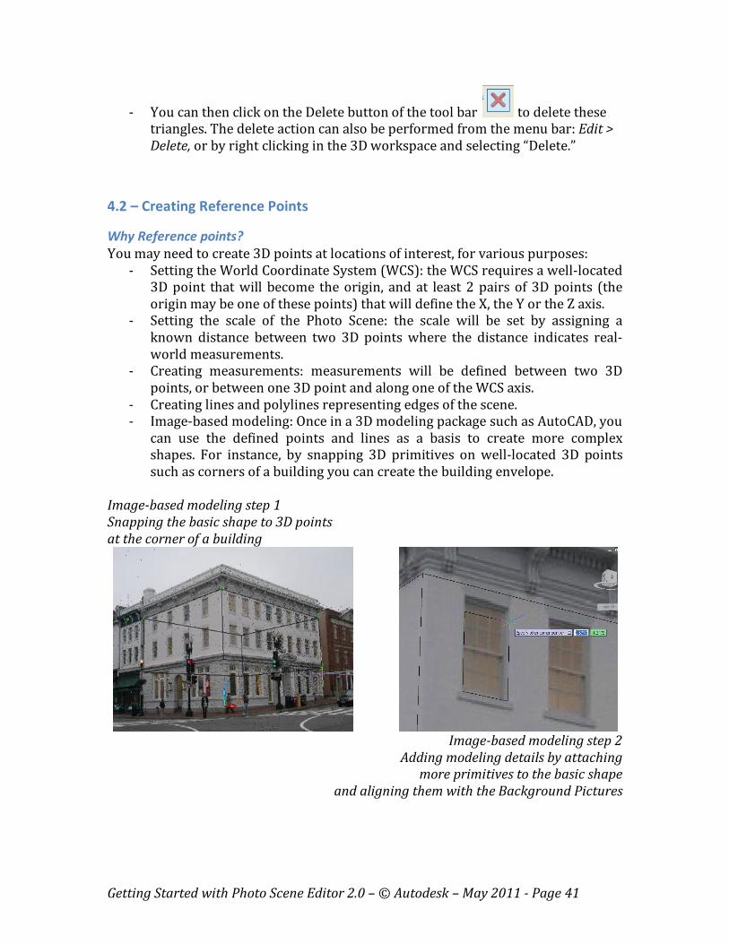
- Image-based modeling: Once in a 3D modeling package such as AutoCAD, you
can use the defined points and lines as a basis to create more complex
shapes. For instance, by snapping 3D primitives on well-located 3D points
such as corners of a building you can create the building envelope.
Image-based modeling step 1
Snapping the basic shape to 3D points
at the corner of a building
Image-based modeling step 2
Adding modeling details by attaching
more primitives to the basic shape
and aligning them with the Background Pictures
Getting Started with Photo Scene Editor 2.0 – © Autodesk – May 2011 - Page 42
Creating a Reference Point
To create a Reference Point, follow the steps below:
- Select your viewpoint: The preferred viewpoint is the one right in front of the
3D point that you want to create.
- Set your visualization mode. The preferred visualization mode for creating
Reference Points is:
o Lock on camera (mandatory)
o Automatic Point Cloud: off
o Splats visualization: on
- Click on in the tool bar, or Edit > Create Reference Point from the menu
bar. Your cursor then appears as in the 3D window.
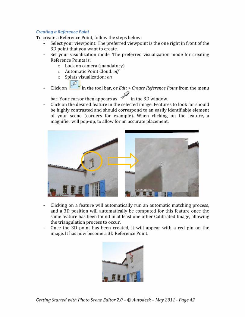
- Click on the desired feature in the selected image. Features to look for should
be highly contrasted and should correspond to an easily identifiable element
of your scene (corners for example). When clicking on the feature, a
magnifier will pop-up, to allow for an accurate placement.
- Clicking on a feature will automatically run an automatic matching process,
and a 3D position will automatically be computed for this feature once the
same feature has been found in at least one other Calibrated Image, allowing
the triangulation process to occur.
- Once the 3D point has been created, it will appear with a red pin on the
image. It has now become a 3D Reference Point.
Getting Started with Photo Scene Editor 2.0 – © Autodesk – May 2011 - Page 43
- The thumbnails will also show:
o The image in which the feature was initially identified, this thumbnail
being highlighted by a green pin.
o Green dots in the other images that give the visual indication that
your 3D point is properly located.
- At this stage, you are done with this 3D Reference Point, and you can create
additional ones once the “Create Reference Point” tool is active (cursor =
).
Adjusting a Reference Point
In some cases, you may find that the 3D Reference Point created from one image is
not properly located in other images. You can then fine tune the manual placement
of the 3D point, using another image, at least, as a reference.
- First select another camera from which the initially selected feature can be
seen as well, but from a substantially different angle: the closer to 90° angle
between 2 viewpoints, the better for the triangulation process. As an
example, selecting the closest neighbor to the first image is typically not
appropriate.
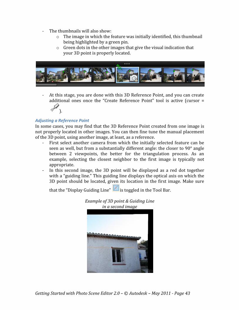
- In this second image, the 3D point will be displayed as a red dot together
with a “guiding line.” This guiding line displays the optical axis on which the
3D point should be located, given its location in the first image. Make sure
that the “Display Guiding Line” is toggled in the Tool Bar.
Example of 3D point & Guiding Line
in a second image
Getting Started with Photo Scene Editor 2.0 – © Autodesk – May 2011 - Page 44
- The cursor must appear as , which indicates that you are in the
adjustment mode. Clicking on the picture will then pop-up the magnifier
again. You can then easily adjust the placement of the point along this
guiding line, or close to it. Once you release the click, the triangulation
process is run again to create the 3D Reference Point.
- You may repeat this process for a 3rd and a 4th image to increase the accuracy
of your Reference Point.
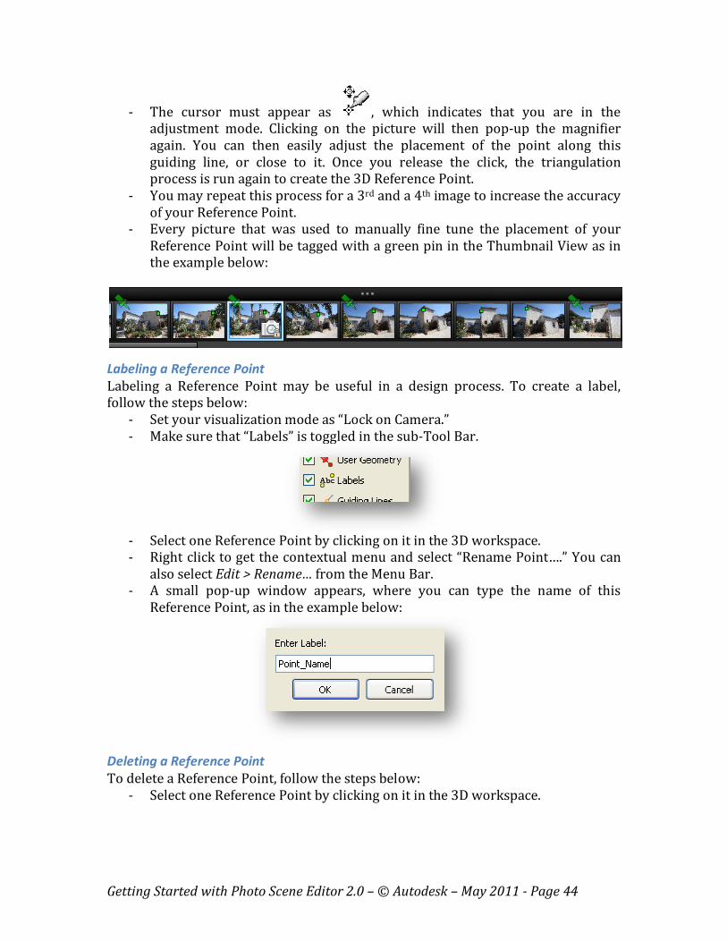
- Every picture that was used to manually fine tune the placement of your
Reference Point will be tagged with a green pin in the Thumbnail View as in
the example below:
Labeling a Reference Point
Labeling a Reference Point may be useful in a design process. To create a label,
follow the steps below:
- Set your visualization mode as “Lock on Camera.”
- Make sure that “Labels” is toggled in the sub-Tool Bar.
- Select one Reference Point by clicking on it in the 3D workspace.
- Right click to get the contextual menu and select “Rename Point….” You can
also select Edit > Rename… from the Menu Bar.
- A small pop-up window appears, where you can type the name of this
Reference Point, as in the example below:
Deleting a Reference Point
To delete a Reference Point, follow the steps below:
- Select one Reference Point by clicking on it in the 3D workspace.
Getting Started with Photo Scene Editor 2.0 – © Autodesk – May 2011 - Page 45
- Right click to get the contextual menu and select “Delete Point.” You can also
select Edit > Delete from the Menu Bar, or click on in the Tool Bar.
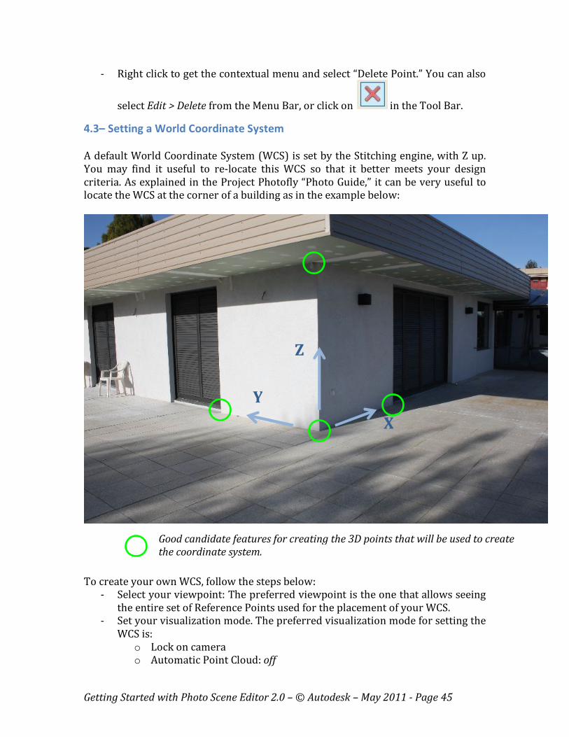
4.3– Setting a World Coordinate System
A default World Coordinate System (WCS) is set by the Stitching engine, with Z up.
You may find it useful to re-locate this WCS so that it better meets your design
criteria. As explained in the Project Photofly “Photo Guide,” it can be very useful to
locate the WCS at the corner of a building as in the example below:
To create your own WCS, follow the steps below:
- Select your viewpoint: The preferred viewpoint is the one that allows seeing
the entire set of Reference Points used for the placement of your WCS.
- Set your visualization mode. The preferred visualization mode for setting the
WCS is:
o Lock on camera
o Automatic Point Cloud: off
Y
X
Z
Good candidate features for creating the 3D points that will be used to create
the coordinate system.

Getting Started with Photo Scene Editor 2.0 – © Autodesk – May 2011 - Page 46
o Splats visualization: on
- Click on in the Tool Bar to enter the WCS creation mode. You can also
click on: Edit > Define World Space in the Menu Bar. The following WCS icon
appears somewhere in your 3D workspace:
- Place the origin first, by clicking on the corresponding dot in the WCS icon,
and attaching it to one Reference Point.
- Place a first axis then, by clicking on one or both dots defining each axis in the
WCS icon. The selected dot appears in yellow.
o When clicking on the dot opposite to the origin, your selected axis will
move around the origin. You then virtually attach this dot to another
Reference Point that is located along this axis from the origin. In the
example below, the Z axis was attached to a Reference Point exactly
vertical located vertical from the selected origin:
o When clicking on the dot close to the origin, you may locate your
selected axis in a completely different area from the one used
previously. The second dot for the same axis must be moved as well
accordingly, as in the sequence below:
Step 1 – Select 1st dot of X axis Step 2 – Move it to its right place
Getting Started with Photo Scene Editor 2.0 – © Autodesk – May 2011 - Page 47
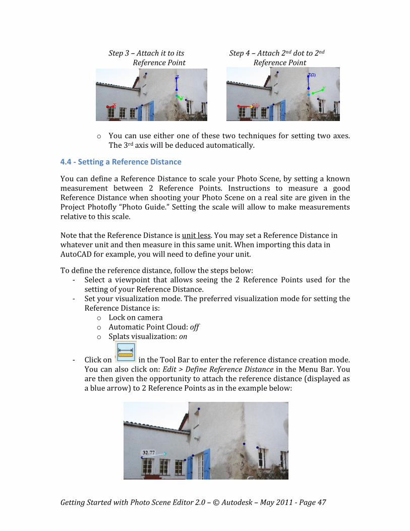
Step 3 – Attach it to its Step 4 – Attach 2nd dot to 2nd
Reference Point Reference Point
o You can use either one of these two techniques for setting two axes.
The 3rd axis will be deduced automatically.
4.4 - Setting a Reference Distance
You can define a Reference Distance to scale your Photo Scene, by setting a known
measurement between 2 Reference Points. Instructions to measure a good
Reference Distance when shooting your Photo Scene on a real site are given in the
Project Photofly “Photo Guide.” Setting the scale will allow to make measurements
relative to this scale.
Note that the Reference Distance is unit less. You may set a Reference Distance in
whatever unit and then measure in this same unit. When importing this data in
AutoCAD for example, you will need to define your unit.
To define the reference distance, follow the steps below:
- Select a viewpoint that allows seeing the 2 Reference Points used for the
setting of your Reference Distance.
- Set your visualization mode. The preferred visualization mode for setting the
Reference Distance is:
o Lock on camera
o Automatic Point Cloud: off
o Splats visualization: on
- Click on in the Tool Bar to enter the reference distance creation mode.
You can also click on: Edit > Define Reference Distance in the Menu Bar. You
are then given the opportunity to attach the reference distance (displayed as
a blue arrow) to 2 Reference Points as in the example below:

Getting Started with Photo Scene Editor 2.0 – © Autodesk – May 2011 - Page 48
- Once you place the second end of the arrow to the second Reference Point, a
pop-up windows appears, in which you can enter the value of the real
measurement:
- Clicking on “OK” will scale the entire Photo Scene.
- You can reset this reference distance by right clicking in the 3D workspace
and selecting “Reset Reference Distance” in the contextual menu.
- You can also click again on in the Tool Bar to set a new value. In which
case, you will be prompted the following message:
- Click on “OK” to delete the former value, and you can then create your
Reference Distance again.
4.5 – Making Measurements
You can measure distances between 2 Reference Points, or between one Reference
Point and along one axis of the WCS. Distances are relative to the Reference Distance
that you previously set up.
To create a measurement, follow the steps below:
- Select a viewpoint that allows seeing the 2 Reference Points used for the
measurement.
- Set your visualization mode to:
o Lock on camera (mandatory)
Getting Started with Photo Scene Editor 2.0 – © Autodesk – May 2011 - Page 49
o Automatic Point Cloud: off
o Splats visualization: on
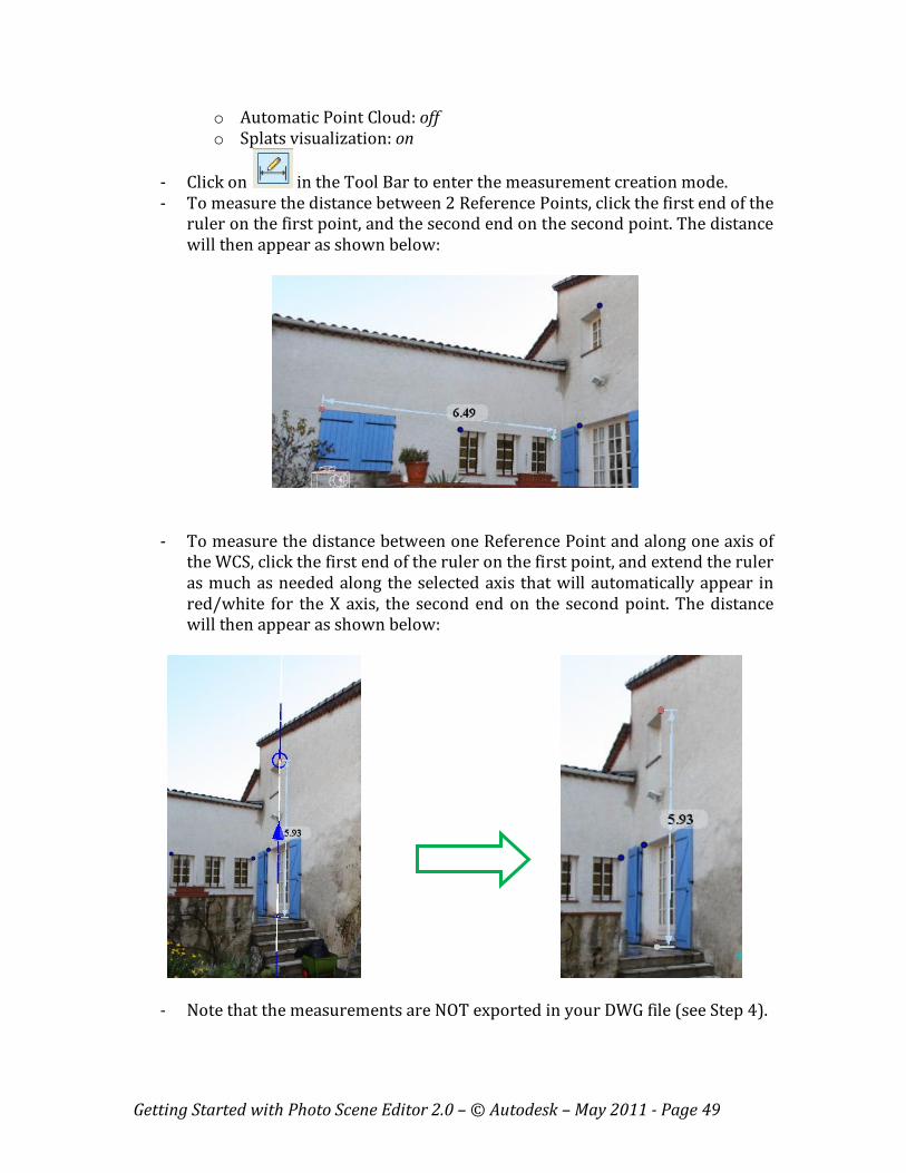
- Click on in the Tool Bar to enter the measurement creation mode.
- To measure the distance between 2 Reference Points, click the first end of the
ruler on the first point, and the second end on the second point. The distance
will then appear as shown below:
- To measure the distance between one Reference Point and along one axis of
the WCS, click the first end of the ruler on the first point, and extend the ruler
as much as needed along the selected axis that will automatically appear in
red/white for the X axis, the second end on the second point. The distance
will then appear as shown below:
- Note that the measurements are NOT exported in your DWG file (see Step 4).
Getting Started with Photo Scene Editor 2.0 – © Autodesk – May 2011 - Page 50
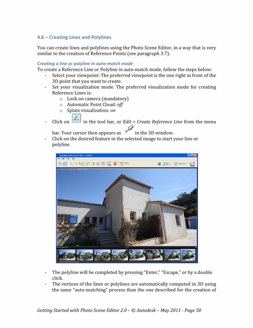
4.6 – Creating Lines and Polylines
You can create lines and polylines using the Photo Scene Editor, in a way that is very
similar to the creation of Reference Points (see paragraph 3.7).
Creating a line or polyline in auto-match mode
To create a Reference Line or Polyline in auto-match mode, follow the steps below:
- Select your viewpoint: The preferred viewpoint is the one right in front of the
3D point that you want to create.
- Set your visualization mode. The preferred visualization mode for creating
Reference Lines is:
o Lock on camera (mandatory)
o Automatic Point Cloud: off
o Splats visualization: on
- Click on in the tool bar, or Edit > Create Reference Line from the menu
bar. Your cursor then appears as in the 3D window.
- Click on the desired feature in the selected image to start your line or
polyline.
- The polyline will be completed by pressing “Enter,” “Escape,” or by a double
click.
- The vertices of the lines or polylines are automatically computed in 3D using
the same “auto-matching” process than the one described for the creation of
Getting Started with Photo Scene Editor 2.0 – © Autodesk – May 2011 - Page 51
3D Reference Point (paragraph 3.7). This process may take some time,
depending on the number of vertices and the number or photos in your
project. During this process, the polyline is adjusted automatically:
o More points will be computed between two vertices by the auto-
match engine if the corresponding line follows a high contrast edge, to
make it more accurate.
o Starting from the 3rd line segment, the auto-match engine will check if
this line segment should not be in the same planar surface than the
one defined by the 2 first lines. If it is close to it, it will automatically
adjust this 3rd one to be co-planar with the first 2 ones.
- You may adjust these vertices the same way that you can adjust Reference
Points (see “Adjusting a Reference Point” in paragraph 3.7).
- The Reference Lines and polylines created with the Photo Scene Editor will
be exported in the DWG file (see Step 4).
Creating a line or polyline in constrained mode
It may be useful to create lines or polylines by following the axis or planes defined
by your WCS:
- It will ensure the planarity of your set of lines, should they be planar.
- You can define planar sections.
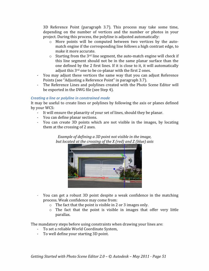
- You can create 3D points which are not visible in the images, by locating
them at the crossing of 2 axes.
Example of defining a 3D point not visible in the image,
but located at the crossing of the X (red) and Z (blue) axis
- You can get a robust 3D point despite a weak confidence in the matching
process. Weak confidence may come from:
o The fact that the point is visible in 2 or 3 images only.
o The fact that the point is visible in images that offer very little
parallax.
The mandatory steps before using constraints when drawing your lines are:
- To set a reliable World Coordinate System,
- To well define your starting 3D point.

Getting Started with Photo Scene Editor 2.0 – © Autodesk – May 2011 - Page 52
To create a Reference Line or Polyline in constrained mode, follow the steps below:
- Select your viewpoint: The preferred viewpoint is the one right in front of the
3D point that you want to create.
- Set your visualization mode. The preferred visualization mode for creating
Reference Lines is:
o Lock on camera (mandatory)
o Automatic Point Cloud: off
o Splats visualization: on
- Click on in the tool bar, or Edit > Create Reference Line from the menu
bar. Your cursor then appears as in the 3D window.
- Click on the desired feature in the selected image to start your line or
polyline.
- The following shortcuts are available to work in this mode:
o A: Toggle auto-snapping to axes
o Shift: Lock/unlock to axis constraint
o Tab: Cycle constraints
o Ctrl : To avoid any new snapping
o ESC: Exit the tool and validate the line created
o Backspace: Delete the previous segment of the line
- You can select which constraint to use by either right clicking in the 3D view
or pressing “Tab” several times.
o Right clicking will pop-up the following window:
Getting Started with Photo Scene Editor 2.0 – © Autodesk – May 2011 - Page 53
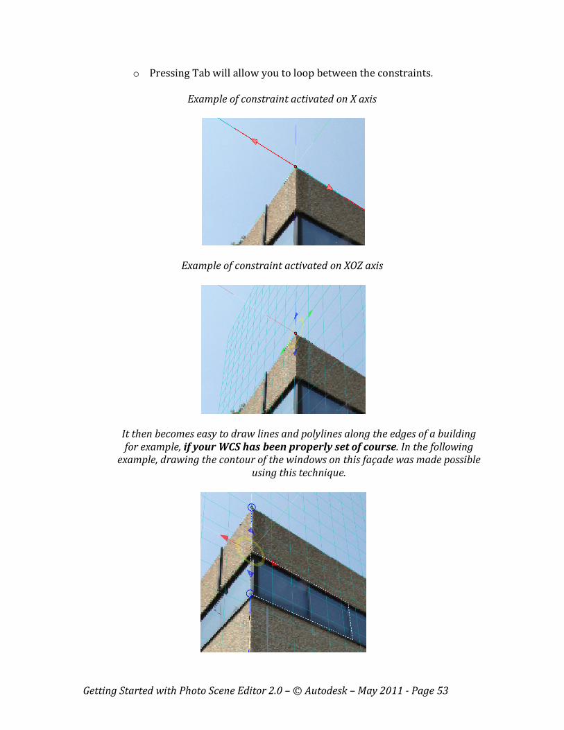
o Pressing Tab will allow you to loop between the constraints.
Example of constraint activated on X axis
Example of constraint activated on XOZ axis
It then becomes easy to draw lines and polylines along the edges of a building
for example, if your WCS has been properly set of course. In the following
example, drawing the contour of the windows on this façade was made possible
using this technique.
Getting Started with Photo Scene Editor 2.0 – © Autodesk – May 2011 - Page 54
Chapter 4 – Export of the Photo Scene
You can export the entire Photo Scene or a selection of its components, in DWG, OBJ,
LAS, IPM or RZI format.
- DWG is the abbreviation for DraWinG, the native drawing file format for
Autodesk applications. DWG files created by the Photo Scene Editor can be
read in any Autodesk software starting from 2010 version. They contain 2
layers:
o Reference Points and Lines
o Reference Points Labels
Should you want to export the 3D Point Cloud as well, you will need to export it
separately in LAS format. See below.
- The OBJ is a 3D geometry definition file format with .obj file extension, which
contains the photo textured 3D mesh produced by the Photo Scene Editor.
- The LAS file format is a public file format for the interchange of LIDAR data
between vendors and customers. This binary file format is an alternative to
proprietary systems or a generic ASCII file interchange system used by many
companies. More about ASPRS and LAS format on: http://www.asprs.org
The LAS file created by the Photo Scene Editor contains the 3D point cloud
that is automatically extracted from the pixels of the Source Photos, during
the mesh creation process.
- IPM is the Inventor Publisher Mobile format from Autodesk®. The IPM
Viewer allows you to interactively view fixed or animated 3D assembly
instructions created with Autodesk Inventor Publisher software. You can
freely download this viewer for your iPhone, iPad, or iPod Touch (iOS 3.2 or
later), on:
http://itunes.apple.com/fr/app/inventor-publisher-mobile/id393147903?mt=8
- RZI is the Autodesk® ImageModeler® 2009 native file format to save and
load Photo Scenes. RZI files will contain the whole or part of your Photo
Scene, depending on your selection. By default, the entire Photo Scene will be
exported, which means:
o Cameras
o Reference Points
o 3D mesh
o Reference lines
o Distance measures
Getting Started with Photo Scene Editor 2.0 – © Autodesk – May 2011 - Page 55
Exporting a Photo Scene
- To export a Photo Scene, click on File -> Export Scene As… in the menu bar.
This will pop-up the export window, in which you can select your file name
and export format.
Importing the Automatic Point Cloud in AutoCAD using the LAS format
Please, follow the steps below to import your Automatic Point Cloud in AutoCAD:
- Load the corresponding drawing first (*.dwg)
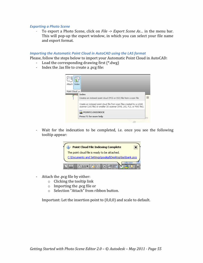
- Index the .las file to create a .pcg file:
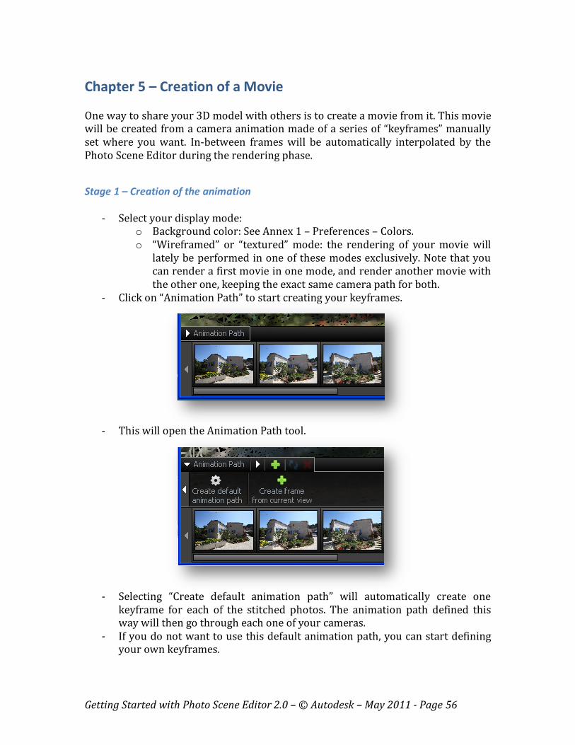
- Wait for the indexation to be completed, i.e. once you see the following
tooltip appear:
- Attach the .pcg file by either:
o Clicking the tooltip link
o Importing the .pcg file or
o Selection “Attach” from ribbon button.
Important: Let the insertion point to (0,0,0) and scale to default.
Getting Started with Photo Scene Editor 2.0 – © Autodesk – May 2011 - Page 56
Chapter 5 – Creation of a Movie
One way to share your 3D model with others is to create a movie from it. This movie
will be created from a camera animation made of a series of “keyframes” manually
set where you want. In-between frames will be automatically interpolated by the
Photo Scene Editor during the rendering phase.
Stage 1 – Creation of the animation
- Select your display mode:
o Background color: See Annex 1 – Preferences – Colors.
o “Wireframed” or “textured” mode: the rendering of your movie will
lately be performed in one of these modes exclusively. Note that you
can render a first movie in one mode, and render another movie with
the other one, keeping the exact same camera path for both.
- Click on “Animation Path” to start creating your keyframes.
- This will open the Animation Path tool.
- Selecting “Create default animation path” will automatically create one
keyframe for each of the stitched photos. The animation path defined this
way will then go through each one of your cameras.
- If you do not want to use this default animation path, you can start defining
your own keyframes.
Getting Started with Photo Scene Editor 2.0 – © Autodesk – May 2011 - Page 57
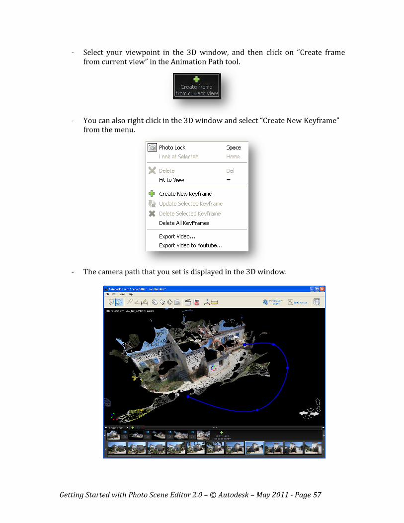
- Select your viewpoint in the 3D window, and then click on “Create frame
from current view” in the Animation Path tool.
- You can also right click in the 3D window and select “Create New Keyframe”
from the menu.
- The camera path that you set is displayed in the 3D window.
Getting Started with Photo Scene Editor 2.0 – © Autodesk – May 2011 - Page 58
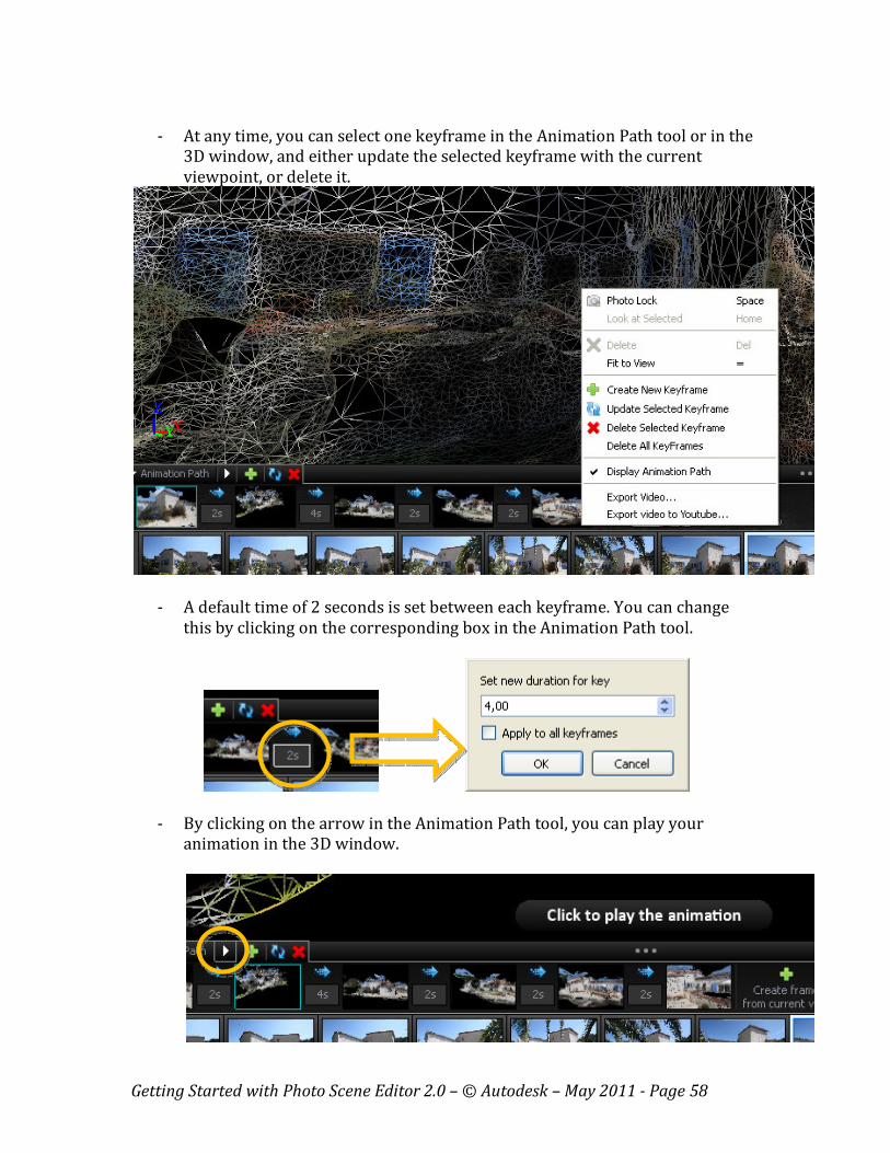
- At any time, you can select one keyframe in the Animation Path tool or in the
3D window, and either update the selected keyframe with the current
viewpoint, or delete it.
- A default time of 2 seconds is set between each keyframe. You can change
this by clicking on the corresponding box in the Animation Path tool.
- By clicking on the arrow in the Animation Path tool, you can play your
animation in the 3D window.
Getting Started with Photo Scene Editor 2.0 – © Autodesk – May 2011 - Page 59
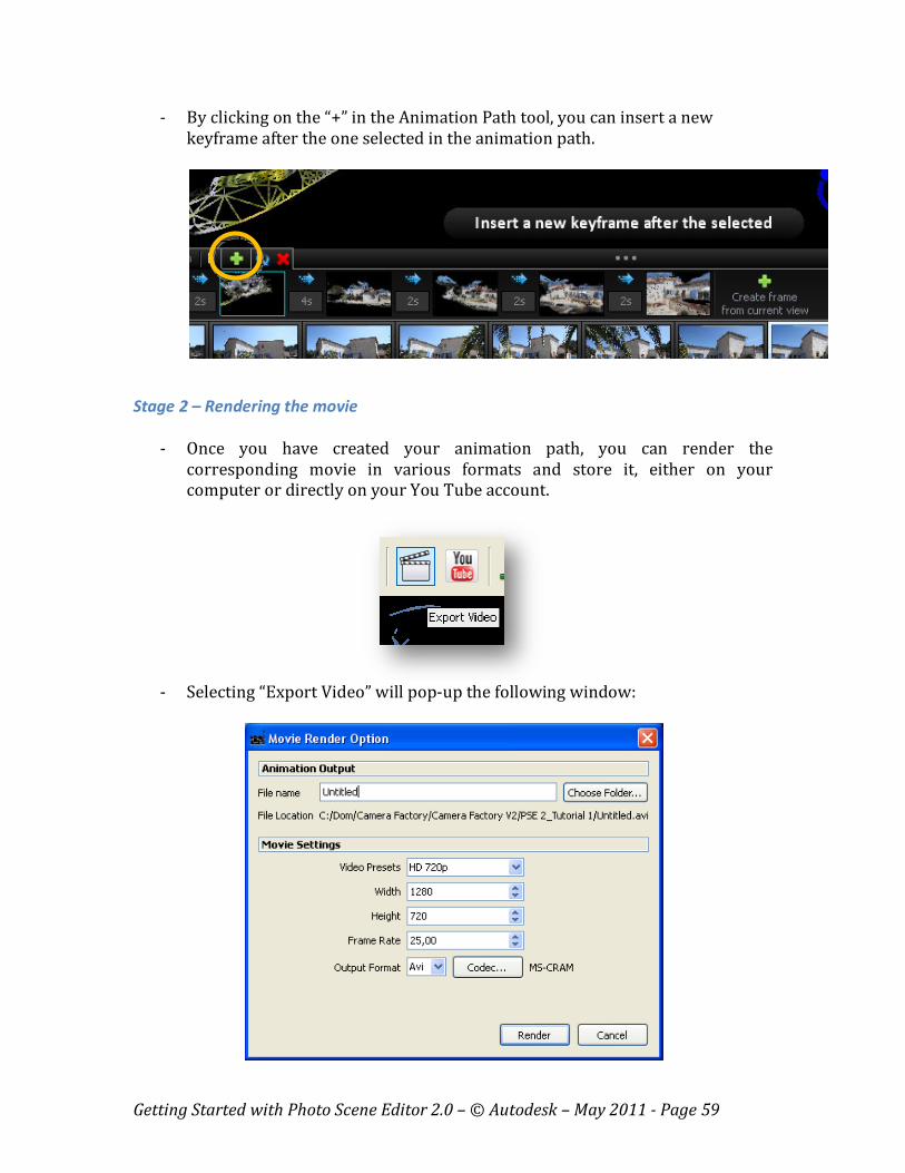
- By clicking on the “+” in the Animation Path tool, you can insert a new
keyframe after the one selected in the animation path.
Stage 2 – Rendering the movie
- Once you have created your animation path, you can render the
corresponding movie in various formats and store it, either on your
computer or directly on your You Tube account.
- Selecting “Export Video” will pop-up the following window:
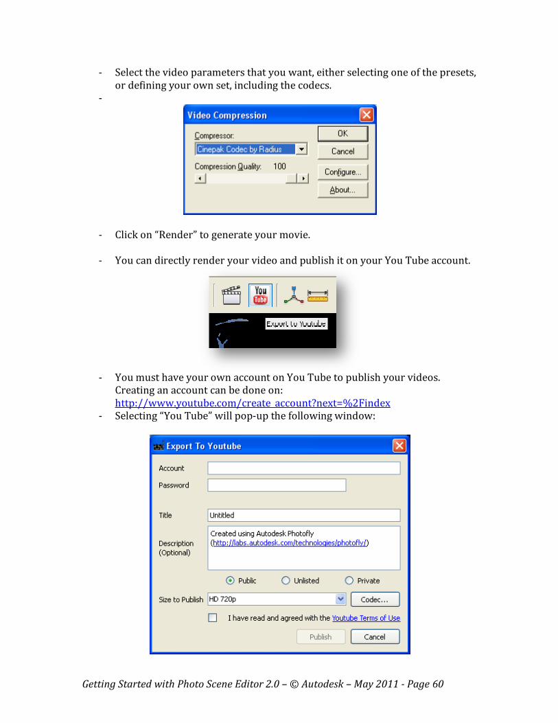
Getting Started with Photo Scene Editor 2.0 – © Autodesk – May 2011 - Page 60
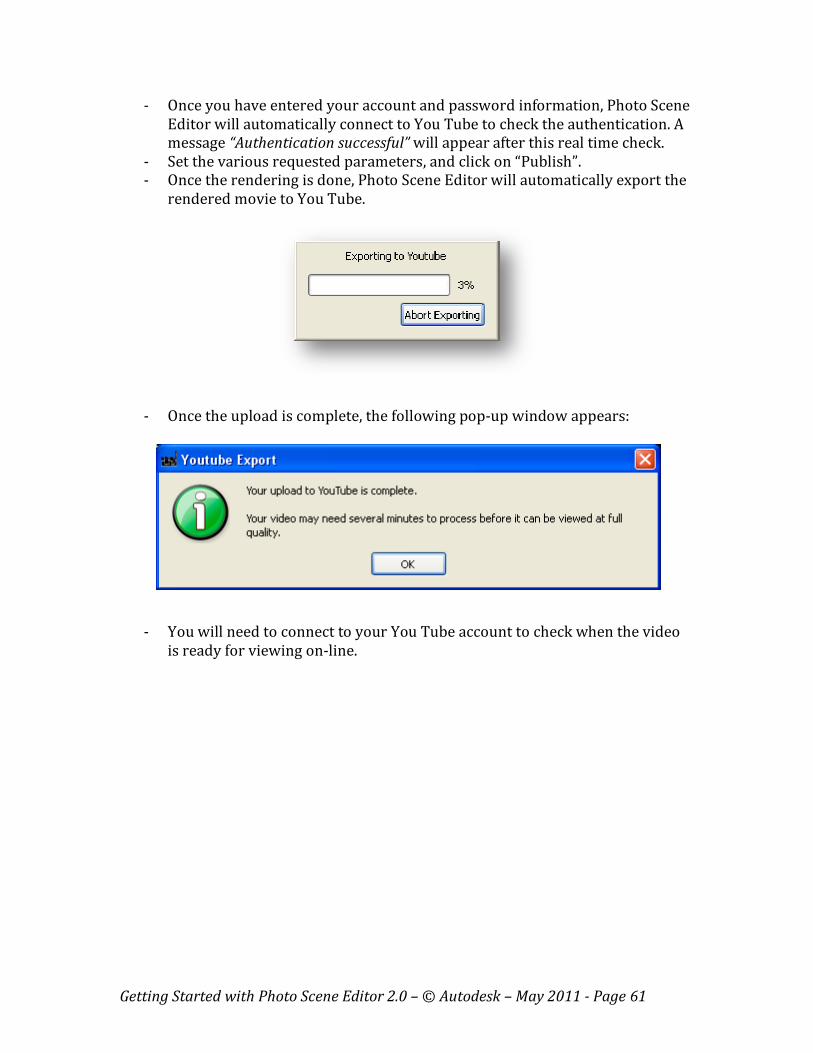
- Select the video parameters that you want, either selecting one of the presets,
or defining your own set, including the codecs.
-
- Click on “Render” to generate your movie.
- You can directly render your video and publish it on your You Tube account.
- You must have your own account on You Tube to publish your videos.
Creating an account can be done on:
http://www.youtube.com/create_account?next=%2Findex
- Selecting “You Tube” will pop-up the following window:
Getting Started with Photo Scene Editor 2.0 – © Autodesk – May 2011 - Page 61
- Once you have entered your account and password information, Photo Scene
Editor will automatically connect to You Tube to check the authentication. A
message “Authentication successful” will appear after this real time check.
- Set the various requested parameters, and click on “Publish”.
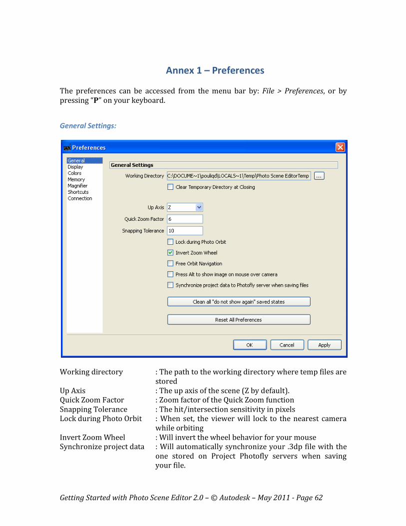
- Once the rendering is done, Photo Scene Editor will automatically export the
rendered movie to You Tube.
- Once the upload is complete, the following pop-up window appears:
- You will need to connect to your You Tube account to check when the video
is ready for viewing on-line.
Getting Started with Photo Scene Editor 2.0 – © Autodesk – May 2011 - Page 62
Annex 1 – Preferences
The preferences can be accessed from the menu bar by: File > Preferences, or by
pressing “P” on your keyboard.
General Settings:
Working directory : The path to the working directory where temp files are
stored
Up Axis : The up axis of the scene (Z by default).
Quick Zoom Factor : Zoom factor of the Quick Zoom function
Snapping Tolerance : The hit/intersection sensitivity in pixels
Lock during Photo Orbit : When set, the viewer will lock to the nearest camera
while orbiting
Invert Zoom Wheel : Will invert the wheel behavior for your mouse
Synchronize project data : Will automatically synchronize your .3dp file with the
one stored on Project Photofly servers when saving
your file.
Getting Started with Photo Scene Editor 2.0 – © Autodesk – May 2011 - Page 63
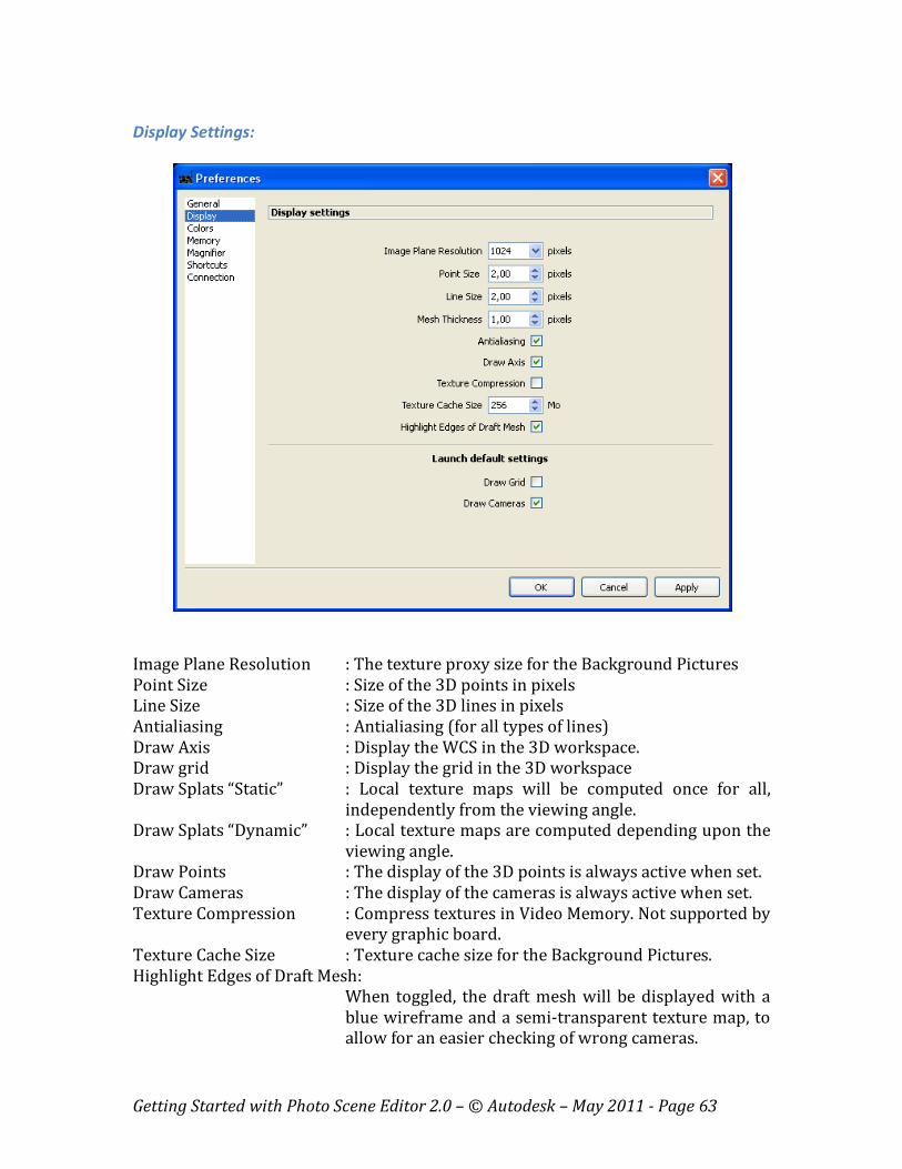
Display Settings:
Image Plane Resolution : The texture proxy size for the Background Pictures
Point Size : Size of the 3D points in pixels
Line Size : Size of the 3D lines in pixels
Antialiasing : Antialiasing (for all types of lines)
Draw Axis : Display the WCS in the 3D workspace.
Draw grid : Display the grid in the 3D workspace
Draw Splats “Static” : Local texture maps will be computed once for all,
independently from the viewing angle.
Draw Splats “Dynamic” : Local texture maps are computed depending upon the
viewing angle.
Draw Points : The display of the 3D points is always active when set.
Draw Cameras : The display of the cameras is always active when set.
Texture Compression : Compress textures in Video Memory. Not supported by
every graphic board.
Texture Cache Size : Texture cache size for the Background Pictures.
Highlight Edges of Draft Mesh:
When toggled, the draft mesh will be displayed with a
blue wireframe and a semi-transparent texture map, to
allow for an easier checking of wrong cameras.
Getting Started with Photo Scene Editor 2.0 – © Autodesk – May 2011 - Page 64
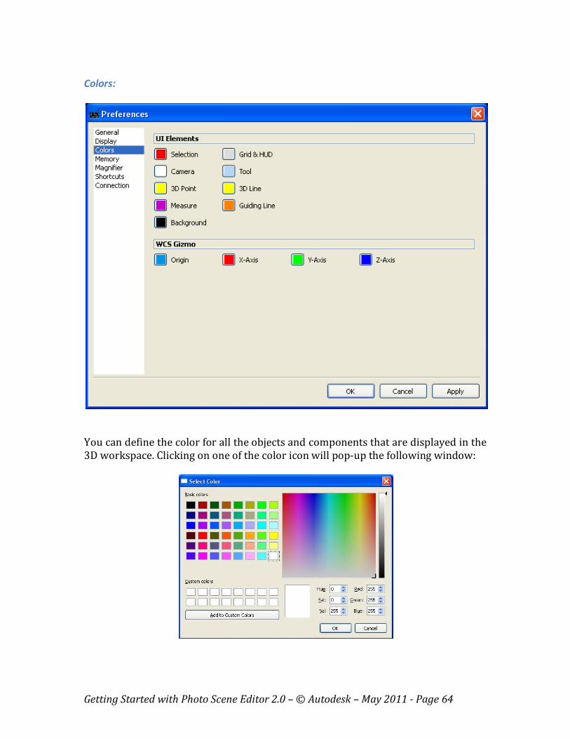
Colors:
You can define the color for all the objects and components that are displayed in the
3D workspace. Clicking on one of the color icon will pop-up the following window:
Getting Started with Photo Scene Editor 2.0 – © Autodesk – May 2011 - Page 65
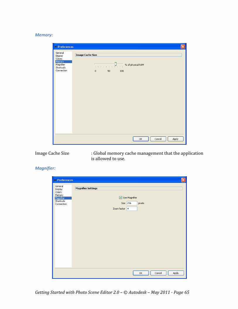
Memory:
Image Cache Size : Global memory cache management that the application
is allowed to use.
Magnifier:
Getting Started with Photo Scene Editor 2.0 – © Autodesk – May 2011 - Page 66
The magnifier is the pop-up window used for an accurate placement of the cursor
when creating a Reference Point.
Use Magnifier : Defines the use or not of the magnifier when creating
Reference Points (set to “on” by default)
Size : The window size in pixel of the magnifier
Zoom factor : The zoom factor of the magnifier
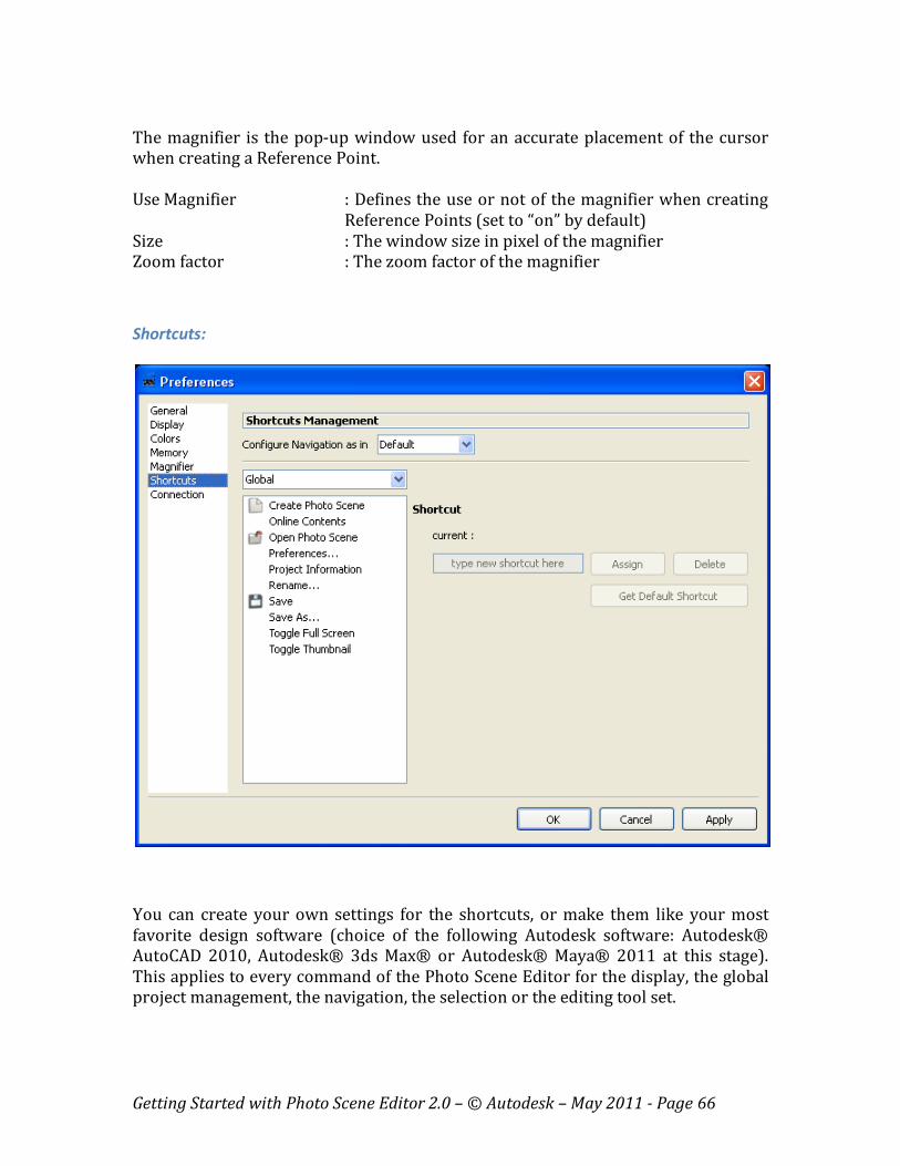
Shortcuts:
You can create your own settings for the shortcuts, or make them like your most
favorite design software (choice of the following Autodesk software: Autodesk®
AutoCAD 2010, Autodesk® 3ds Max® or Autodesk® Maya® 2011 at this stage).
This applies to every command of the Photo Scene Editor for the display, the global
project management, the navigation, the selection or the editing tool set.

Getting Started with Photo Scene Editor 2.0 – © Autodesk – May 2011 - Page 67
To create a new shortcut, select the corresponding command in one of the 5
categories, type the new shortcut on your keyboard, and click on “Assign” to make it
active.
Connection:
- “Automatically detect settings” is your default configuration. The software
will try to automatically detect settings, or use the parameters set by default
in your Internet Explorer, should they be set. - “Use configuration script”: Ask your IT Administrator to provide you with
your .pac file, if any, and enter the corresponding address in the given field.
- “Use a proxy server”: Ask your IT administrator to provide you with your IP
address and port.
- “Authentication”: Enter the Login and Password if required.
Please note that you must disable the automatic configuration if you manually enter
proxy server settings.

Getting Started with Photo Scene Editor 2.0 – © Autodesk – May 2011 - Page 68
Annex 2 – Error Messages
1 - Error Messages from the Photo Scene Editor
Error Messages
Connection Error
You may not be connected to the Internet, or
you may be connected behind a proxy server.
Check the procedure to edit and set your proxy
settings in paragraph 2.2 and in Annex 1 –
Preferences - Connection
Your Photo Scene Editor has expired.
The Photo Scene Editor includes a time bomb.
Check on:
http://labs.autodesk.com/utilities/photo_scene_editior/ for information about updates or evolutions of
the product.
An error occurred with the Web
Service.
Your project has not been computed correctly on
the server. You should try again, including the
upload of your Images. Check the “Error
Messages linked to the Automatic Stitching
Engine” for more details.
A Photo Scene must contain at least
3 Images.
The Project Photofly Web Service requires 3
images at least to run.
Cannot save the intermediate
project file.
Check your access rights or disk
space.
This problem may occur when you do not have
the access rights for the folder where temporary
files are stored, or if you are running out of disk
space.
The selected Images could
not be stitched.
Please select other Images
and try again.
This message will appear if the automatic engine
could not stitch your photos. In most cases, this
is because these photos have not been shot
properly. Please, read carefully the shooting
guidelines on: http://labs.autodesk.com/technologies/photofly/gettin
g_started/
Getting Started with Photo Scene Editor 2.0 – © Autodesk – May 2011 - Page 69
2 - Error Messages from the Automatic Stitching Engine
- Your Photo Scene has been created successfully, however some of the images
are corrupt or failed to upload.
o Action: Check your files and try resubmitting the scene.
- Your Photo Scene has been created successfully, however your images
appear to be taken from the same physical location. Images in a photo scene
cannot be taken from a single spot.
o Action: Try capturing images of your subject from different positions,
and then resubmit the scene. See the Shooting Guidelines for more
information.
http://labs.autodesk.com/technologies/photofly/getting_started/
- Your Photo Scene has been successfully created, but some of the images
could not be stitched.
o Action: Check the Shooting Guidelines for more information, and try
to resubmit a new set of photos.
http://labs.autodesk.com/technologies/photofly/getting_started/
- The application was unable to create your Photo Scene.
o Action: Check the Shooting Guidelines for more information, and try
to resubmit a new set of photos.
http://labs.autodesk.com/technologies/photofly/getting_started/
- The application was unable to create your Photo Scene because there are not
enough images to compute the scene. You must provide at least three images.
o Action: Check the Shooting Guidelines for more information, and try
to resubmit a new set of photos.
http://labs.autodesk.com/technologies/photofly/getting_started/
- The application was unable to create your Photo Scene because some of the
images are corrupt or failed to upload.
o Action: Check your files and try resubmitting the scene.
- The application was unable to create your Photo Scene because no 3D
information could be extracted from your images, as they appear to be taken
from the same physical location. Images in a photo scene cannot be taken
from a single spot.
o Action: Try capturing images of your subject from different positions,
and then resubmit the scene. See the Shooting Guidelines for more
information.
http://labs.autodesk.com/technologies/photofly/getting_started/

Getting Started with Photo Scene Editor 2.0 – © Autodesk – May 2011 - Page 70
- The application was unable to create your Photo Scene because no 3D
information could be extracted from your images, as they do not appear to
overlap. Images in a photo scene must overlap.
o Action: Try capturing overlapping images of your subject, and then
resubmit the scene. See the Shooting Guidelines for more information.
http://labs.autodesk.com/technologies/photofly/getting_started/