autocad -...
TRANSCRIPT

Get wired.
AutoCAD®
Electrical 2008

If your company designs machines or products that move, electrical controls are probably a key component of the design requirement. Until now, electrical controls designers have relied on generic software applications that are problematic because they require the manual layout of electrical schematics, can introduce design errors, and provide no simple way to share design information—a combination that ultimately can cost your company time and money.
The AutoCAD Electrical Advantage
Contents
Reduce Complex or Repetitive Tasks ......3 Reduce Errors ................................................9 Increase Drafting Productivity ............... 13 Communicate and Manage Design Data More Effectively ............................... 17 Learn More or Purchase .......................... 20
2
Take advantage of an application that delivers the tools needed to design and modify electrical controls faster and more accurately than ever before: AutoCAD® Electrical software, built specifically to create and modify electrical controls designs. As part of the AutoCAD® family of software products, AutoCAD Electrical enables users to virtually eliminate errors and provide accurate information to manufacturing, allowing more time for designing and engineering. Stay ahead of the competition with AutoCAD Electrical—the only logical choice for electrical controls design.
Reduce Complex or Repetitive Tasks
�
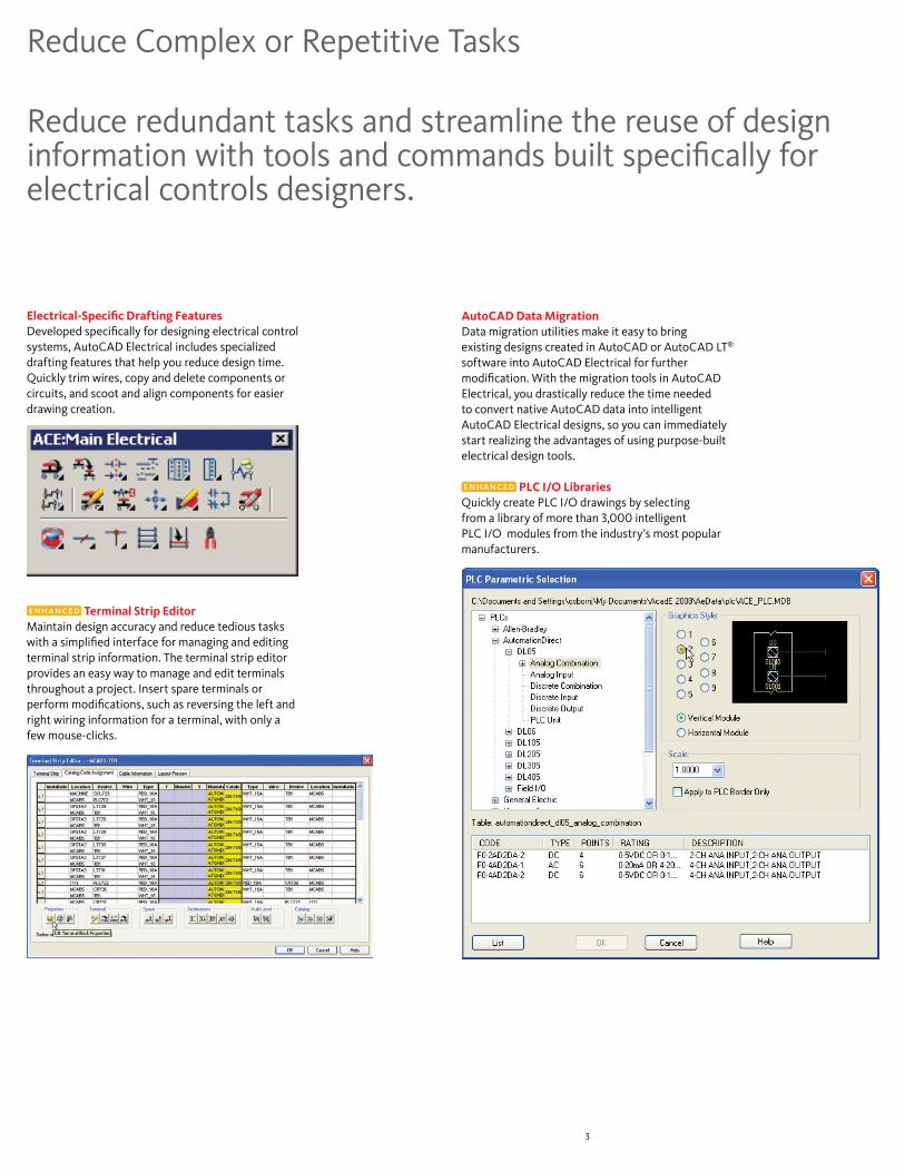
Electrical-Specific Drafting FeaturesDeveloped specifically for designing electrical control systems, AutoCAD Electrical includes specialized drafting features that help you reduce design time. Quickly trim wires, copy and delete components or circuits, and scoot and align components for easier drawing creation.
Terminal Strip EditorMaintain design accuracy and reduce tedious tasks with a simplified interface for managing and editing terminal strip information. The terminal strip editor provides an easy way to manage and edit terminals throughout a project. Insert spare terminals or perform modifications, such as reversing the left and right wiring information for a terminal, with only a few mouse-clicks.
Reduce redundant tasks and streamline the reuse of design information with tools and commands built specifically for electrical controls designers.
AutoCAD Data Migration Data migration utilities make it easy to bring existing designs created in AutoCAD or AutoCAD LT®
software into AutoCAD Electrical for further modification. With the migration tools in AutoCAD Electrical, you drastically reduce the time needed to convert native AutoCAD data into intelligent AutoCAD Electrical designs, so you can immediately start realizing the advantages of using purpose-built electrical design tools.
PLC I/O LibrariesQuickly create PLC I/O drawings by selecting from a library of more than 3,000 intelligent PLC I/O modules from the industry’s most popular manufacturers.

�
Reduce Complex or Repetitive Tasks
PLC I/O Import/ExportReduce design time and minimize errors by reusing crucial design data between AutoCAD Electrical and the corresponding PLC (programmable logic controller) program. Export critical I/O address and description information into multiple file formats. Users can now exchange data bidirectionally between AutoCAD Electrical and Rockwell Automation’s PLC programming software, as well as Schneider Electric’s Unity™ software products.
Installer ImprovementsDuring the installation process, you can select which manufacturer catalogs are included, making it quick and easy to manage the content of your manufacturer’s catalog.
Autodesk DWG Product RecognitionDetermine which Autodesk product created a DWG™ file. When you move the cursor over the DWG icon, a window appears with information identifying the Autodesk product and version used to create the DWG file. In AutoCAD Electrical, an attempt is also made to locate the appropriate Autodesk product needed to open the file.
Content Database Merge UtilityUse this powerful utility to easily merge existing manufacturer catalog databases, PLC I/O libraries, footprint lookup databases, and corresponding footprint symbols with content delivered in each new release. Now you can take full advantage of content additions in new releases without losing previous customizations to existing content libraries.
�
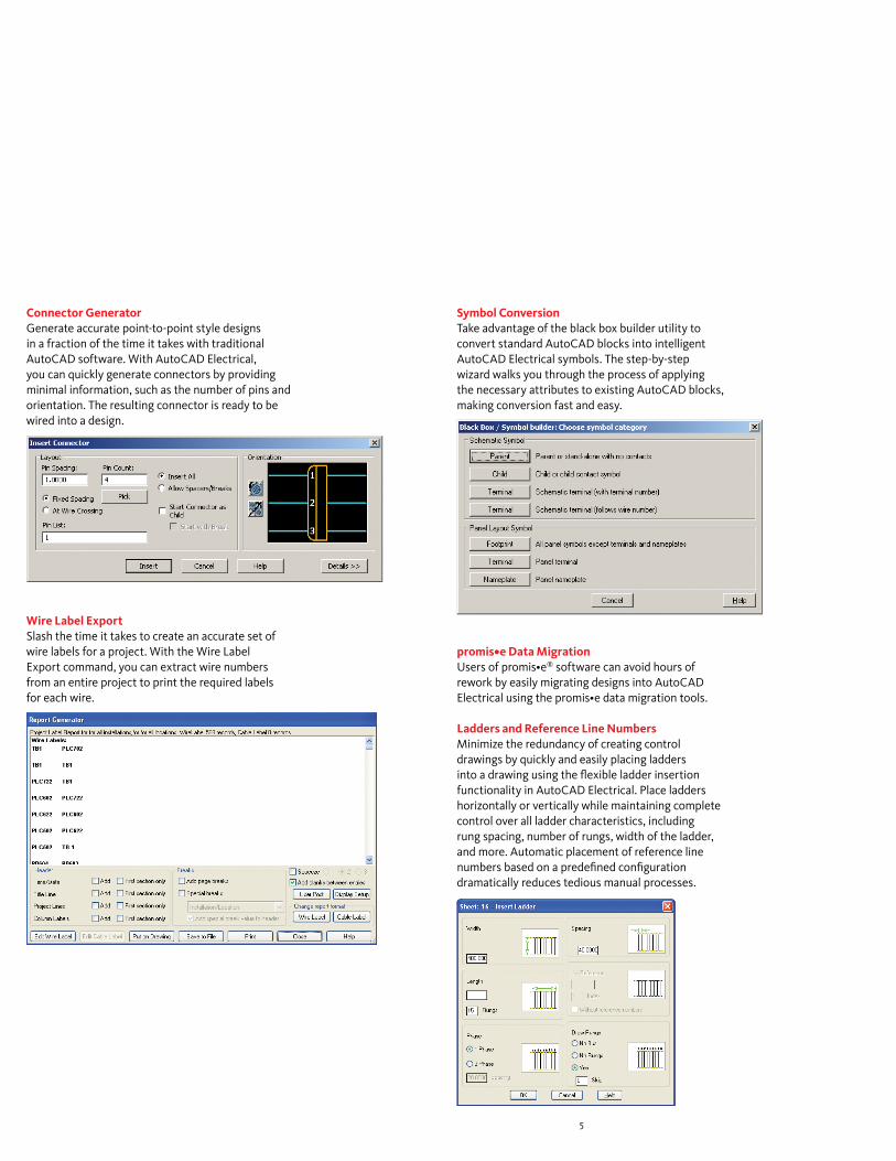
Connector Generator Generate accurate point-to-point style designs in a fraction of the time it takes with traditional AutoCAD software. With AutoCAD Electrical, you can quickly generate connectors by providing minimal information, such as the number of pins and orientation. The resulting connector is ready to be wired into a design.
Wire Label ExportSlash the time it takes to create an accurate set of wire labels for a project. With the Wire Label Export command, you can extract wire numbers from an entire project to print the required labels for each wire.
Symbol ConversionTake advantage of the black box builder utility to convert standard AutoCAD blocks into intelligent AutoCAD Electrical symbols. The step-by-step wizard walks you through the process of applying the necessary attributes to existing AutoCAD blocks, making conversion fast and easy.
promis•e Data Migration Users of promis•e® software can avoid hours of rework by easily migrating designs into AutoCAD Electrical using the promis•e data migration tools.
Ladders and Reference Line NumbersMinimize the redundancy of creating control drawings by quickly and easily placing ladders into a drawing using the flexible ladder insertion functionality in AutoCAD Electrical. Place ladders horizontally or vertically while maintaining complete control over all ladder characteristics, including rung spacing, number of rungs, width of the ladder, and more. Automatic placement of reference line numbers based on a predefined configuration dramatically reduces tedious manual processes.
�
Reduce Complex or Repetitive Tasks
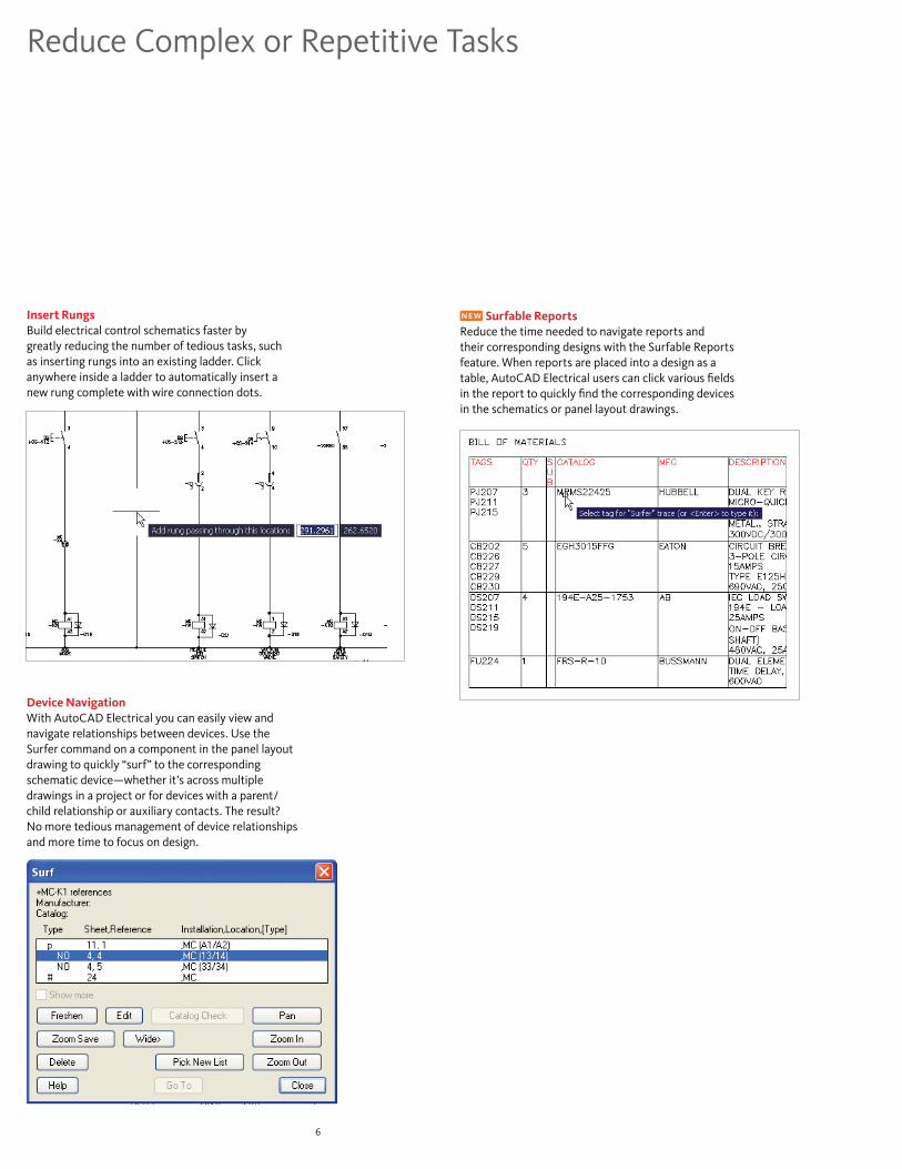
Insert RungsBuild electrical control schematics faster by greatly reducing the number of tedious tasks, such as inserting rungs into an existing ladder. Click anywhere inside a ladder to automatically insert a new rung complete with wire connection dots.
Device NavigationWith AutoCAD Electrical you can easily view and navigate relationships between devices. Use the Surfer command on a component in the panel layout drawing to quickly “surf” to the corresponding schematic device—whether it’s across multiple drawings in a project or for devices with a parent/ child relationship or auxiliary contacts. The result? No more tedious management of device relationships and more time to focus on design.
Surfable ReportsReduce the time needed to navigate reports and their corresponding designs with the Surfable Reports feature. When reports are placed into a design as a table, AutoCAD Electrical users can click various fields in the report to quickly find the corresponding devices in the schematics or panel layout drawings.

7
Swap Block UtilitySave hours of rework by quickly replacing each instance of a symbol throughout a project. Swap instances of a block or an individual symbol wherever it is used in a project. You can even swap symbols for an entire project between two symbol libraries. For example, if you need to change the standard used in a project, just run this command to automatically swap each JIC device out with its IEC equivalent.
Source and Destination MarkersEasily track wires from page to page within a project. When a wire starts on one drawing and continues onto another, you can connect them electronically using the source and destination signals.
Location Boxes and MarkersQuickly and easily associate groups of devices with a specific panel location using the Location Box command. Apply location markers on the schematic that represent the corresponding panel location. This capability makes it easy to identify locations for a device or group of devices, helping to ensure accuracy.

�
Reduce Complex or Repetitive Tasks
Insert Balloons on Panel DevicesSave time by automatically annotating control panel drawings with intelligent item balloons that coincide with the panel bill of materials (BOM).
Wire GapsWhenever two wires cross in an electrical design, AutoCAD Electrical automatically indicates which wire passes through. You can choose from wire gaps, loops, or solid wires to show crossing wires. End result: crisp schematics with no extra effort.

�
Reduce Errors
Automatic Wire Numbering and Component TaggingSpending long hours manually assigning wire numbers and component tags is a thing of the past, as are the potential errors inherent in that process. AutoCAD Electrical automatically places sequential or reference-based numbers on all wires and components, based on the configuration you choose. Reference-based numbers and tags automatically get a suffix when necessary so that names are unique and the software can renumber the entities as the design requirements change. This numbering convention is flexible enough to meet nearly any design requirement.
In addition, if AutoCAD Electrical determines that an inserted wire number will “bump into” something, it automatically searches laterally along the wire for a clear spot to place the wire number. If that fails, it searches for a clear spot away from the wire. When it finds one, it places the number and automatically draws a leader back to the wire.
Inserting Spare TerminalsProvide accurate BOM information by limiting the guesswork when planning for spare terminal needs. Insert spare terminals through the terminal strip editor. Any changes are updated in the BOM and various terminal reports.
Direct to Terminal Wire Sequencing Deliver more accurate reports by taking advantage of the flexibility in the level of control available when defining the wire connection sequence. Land wires from multiple devices onto a common terminal, and have all information accurately reflected in various terminal and wiring reports.
AutoCAD Electrical includes automatic error-checking capabilities that help you avoid errors in real time and catch problems before the build phase of a project. In addition to reducing errors, AutoCAD Electrical helps companies reduce costs by offering support for local and international standards.

Reduce Errors
Automatic Report GenerationReduce the time it takes to create and update reports, as well as reduce the inherent errors in manually generated reports. This major improvement over the functionality available in AutoCAD enables users to run several different reports at once using only one command.
Report generation in AutoCAD Electrical is simple with automatic reports that cover everything from BOM, from/to wire lists, PLC I/O, terminal plans, cable summaries, and cross-referencing reports. Customize reports to display relevant information by sorting and filtering available fields, which can be run on a current drawing, collection of drawings, the entire project, or a specific location or panel in a project. Place reports into a drawing as a smart table object that can be easily updated at a later time or be saved to a file. AutoCAD Electrical supports saving reports in ASCII, Microsoft® Excel®, Microsoft® Access, CSV, or XML formats.
Real-Time Error CheckingAvoid costly errors at build time by catching and removing errors during design. AutoCAD Electrical constantly compares the requested changes with the current project and alerts you to potential errors such as duplicated wire numbers or component tags as they occur.
Real-Time Coil and Contact Cross-ReferencingSignificantly reduce the risk of costly mistakes associated with assigning too many contacts to a relay. AutoCAD Electrical sets up a parent/child relationship between the two and keeps track of how many contacts are assigned to any given coil or multicontact device, so you don’t have to. When you exceed the limit, you get an alert.
Another benefit of this feature is the ability to assign the next available set of terminal pin numbers to each inserted “child” contact, based on the assigned part number of the parent coil. Display cross-referencing information in almost any format on the drawings, and run cross-referencing reports at any time.
10

Smart Panel Layout DrawingsUsing AutoCAD Electrical to create panel layout drawings provides a systematic means to check that no devices are missed and makes an electronic link between the representation of the device in the schematic and panel drawings. Here’s how it works: once you have created a schematic, the software extracts a list of schematic components for placement in the panel layout drawings. All you have to do is pick a device from the list and drag it into place. The physical “footprint” representation of each schematic device is inserted into the layout at the point you select. Then the software creates an electronic link between the schematic and panel device representations. So when you change key data on one drawing, you get a prompt for permission to update the other. You can also add nonschematic items to the layout, such as wire duct and mounting hardware, and they automatically combine into a “smart” panel BOM report.
Reusing CircuitsOnce built, commonly used circuits can then be saved for reuse in future designs, helping to slash design time. When you place a saved circuit into a new design, AutoCAD Electrical automatically renumbers the wires and devices in the circuit to match the configuration of the current drawing or project in which they are placed.
Electrical Audit ReportMissing or incorrect wire numbers can cause major headaches. The audit report analyzes and reports such design anomalies so they can be corrected before they become an expensive problem. An audit report helps you eliminate design errors before they reach the shop floor, saving time and money.
11

Reduce Errors
12
Visual Wiring Sequence IndicatorsGraphically indicate the proper wiring sequence of a circuit directly on the schematic to efficiently communicate design intent to the shop floor, avoiding costly wiring errors. When changes are made to a wire sequence, the updated information is accurately reflected in the from/to wire list report.
Cable and Conductor TrackingManage cable and conductor usage in AutoCAD Electrical projects with easy-to-use tracking capabilities. Designate individual wires as belonging to a cable, and then generate reports based on cable usage for fabrication purposes. Similar to inserting components, when you assign manufacturer part number information to cables, AutoCAD Electrical automatically tracks and reports conductor usage based on that part number.
Retagging Components Reduce design time and help eliminate errors by retagging all components in a project with a single command. This single command enables you to change the format of component tags during a project to accommodate customer changes on the fly.
Fixing Wire Numbers and Component TagsAutoCAD Electrical enables you to easily accommodate design modifications late in the cycle without affecting previous work. When you change the status of wire numbers and component tags to a “fixed” format, they remain unaffected during a projectwide renumbering of wires or retagging of components. If changes are required after the shop floor has the designs, you can easily add new wire numbers and device components without affecting the existing wire numbers.

1�
Increase Drafting Productivity
AutoCAD Electrical also supports international standards and provides a comprehensive library of manufacturer content, enabling users to produce standards-based designs using a consistent set of manufacturer components.
Insert Components from a MenuThe simple menu-driven system in AutoCAD Electrical makes it easy to insert electrical devices. Each menu provides access to a comprehensive symbol library that includes devices such as push buttons, selector switches, pilot lights, relays, contacts, fuses, terminals, and more.
Multi-Level TerminalsUse multi-level terminals to define and manage terminal numbers as well as all connectivity information, with no added complexity.
Since AutoCAD Electrical software is purpose-built, it automates many of the manual tasks associated with creating accurate designs, allowing more time for designing and engineering.
Terminal Jumpers Reduce design time and help eliminate errors by accurately representing terminal jumpers as part of the design. Easily create a “jumper” between multiple terminals to allow them to share the same potential.
Automatic Creation of PLC/IO Drawings from SpreadsheetsGenerate a complete set of PLC I/O drawings simply by defining the project’s I/O assignments in a spreadsheet program. This capability can save you a tremendous amount of design time, because the need to create those drawings in an AutoCAD environment is virtually eliminated. Not only that—all the data remains consistent, since the descriptions on each PLC I/O point can be extracted and imported into your PLC program to help ensure consistency between the drawings and the PLC program.
1�
Increase Drafting Productivity
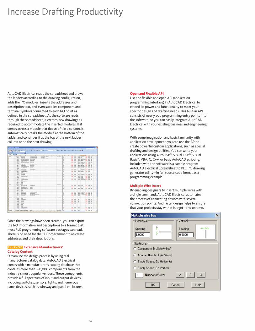
AutoCAD Electrical reads the spreadsheet and draws the ladders according to the drawing configuration, adds the I/O modules, inserts the addresses and description text, and even supplies component and terminal symbols connected to each I/O point as defined in the spreadsheet. As the software reads through the spreadsheet, it creates new drawings as required to accommodate the inserted modules. If it comes across a module that doesn’t fit in a column, it automatically breaks the module at the bottom of the ladder and continues it at the top of the next ladder column or on the next drawing.
Once the drawings have been created, you can export the I/O information and descriptions to a format that most PLC programming software packages can read. There is no need for the PLC programmer to re-create addresses and their descriptions.
Extensive Manufacturers’ Catalog ContentStreamline the design process by using real manufacturer catalog data. AutoCAD Electrical comes with a manufacturer’s catalog database that contains more than 350,000 components from the industry’s most popular vendors. These components provide a full spectrum of input and output devices, including switches, sensors, lights, and numerous panel devices, such as wireway and panel enclosures.
Open and Flexible APIUse the flexible and open API (application programming interface) in AutoCAD Electrical to extend its power and functionality to meet your specific design and drafting needs. This built-in API consists of nearly 200 programming entry points into the software, so you can easily integrate AutoCAD Electrical with your existing business and engineering systems.
With some imagination and basic familiarity with application development, you can use the API to create powerful custom applications, such as special drafting and design utilities. You can write your applications using AutoLISP®, Visual LISP®, Visual Basic®, VBA, C, C++, or basic AutoCAD scripting. Included with the software is a sample program—AutoCAD Electrical Spreadsheet to PLC I/O drawing generator utility—in full source code format as a programming example.
Multiple Wire InsertBy enabling designers to insert multiple wires with a single command, AutoCAD Electrical automates the process of connecting devices with several connection points. And faster design helps to ensure that your projects stay within budget—and on time.

1�
Drawing CommandWith a single click of a button, you can begin a new drawing and know that AutoCAD Electrical is fully aware of the current project settings. After you choose a template with the appropriate title block and drawing border, the new drawing automatically becomes part of the active project and you are ready to start inserting devices.
PerformanceAutoCAD Electrical 2008 software includes significant improvements in running commands that affect many other drawings.
Graphical Terminal Strip GeneratorSlash design time by automatically generating graphical terminal strip layouts based on schematic design information for use in panel layout drawings or terminal plans. You can choose to generate these terminal strips in a graphical or table format. Terminal strip layouts are automatically populated with the wiring information for each side of the strip as defined in the terminal strip editor.
Starting Designs with a Panel Layout DrawingAutoCAD Electrical provides a flexible design environment that works the way you want to work. You can start designs by creating a panel layout drawing and using it to drive the creation of the corresponding logical control schematics. This feature gives you the boost you need for tight turnaround times and supports the needs of individual designers.
Multiuser Environment Share projects within workgroups for collaborative design and increased productivity. The multiuser environment in AutoCAD Electrical provides drawing status indicators and better control of projectwide commands to improve team members’ ability to work in a collaborative environment.

1�
Increase Drafting Productivity
PLC Module BuilderThe PLC module builder functionality makes it easier to add PLC I/O modules to the standard library. If the module you want isn’t included in the current library, you can easily add the ones you need through a graphical interface.
Multidiscipline Symbol Libraries Quickly generate accurate pneumatic, hydraulic, and P&ID schematics using the comprehensive symbol libraries that include devices such as valves, operators, manifolds, meters, regulators, filters, and more.
Support for Multiple Design StandardsYou are always in sync with your customers’ design standards whether it be a JIC, IEC, JIS, or GB design. AutoCAD Electrical provides symbol libraries, cross-reference settings, wire and device tagging conventions, and much more to meet local design requirements.
Three-Phase Motor ControlQuickly design three-phase motor circuits using intelligent, built-in symbol libraries that include three-pole breakers, switches, motor contactors, and more. These symbols automatically adapt to the underlying three-phase rung spacing upon insertion, saving time and helping to keep you productive.
Toggle Normally Open/Normally ClosedWith a single mouse-click, switch the state of a device from normally open to normally closed, and vice versa. If that device is part of a parent/child relationship, such as a relay coil and contact, AutoCAD Electrical automatically updates the corresponding device.

17
Communicate and Manage Design Data More Effectively
Organize, find, and reuse valuable design data. AutoCAD Electrical includes fully integrated data management tools that securely store and manage your work-in-progress design data.
Easily incorporate your electrical controls designs into your mechanical designs. AutoCAD Electrical enables both electrical and mechanical teams to work collaboratively by making it easy to share the electrical intent from the controls design in AutoCAD Electrical with other Autodesk® applications.
Link to Cable and Harness Functionality of Autodesk Inventor Professional Pass electrical intent information for cables and conductors to Autodesk® Inventor™ Professional software to automatically create a 3D harness design. And now Autodesk Inventor Professional users can pass wire-connectivity information to AutoCAD Electrical and automatically create the corresponding 2D schematics. Smooth integration between AutoCAD Electrical and Inventor Professional enables the creation of accurate 2D and 3D electrical designs in less time than when using any other solution on the market.
Sharing Drawings and Tracking Changes AutoCAD Electrical makes it easy to work with other AutoCAD users because anyone with a DWG-compatible program such as AutoCAD or AutoCAD LT can view and edit AutoCAD Electrical files. With the built-in AutoCAD Electrical revision tracking functionality, no matter how many people access your drawings, you can track all changes made to the drawings since the last update.
Publishing Designs on the WebAutoCAD Electrical makes it easy to share your designs over the Internet by publishing either individual drawings or entire projects. AutoCAD Electrical creates the HTML pages and links needed to post your complete design to the web. As an option, you can allow customers or vendors to drag the drawings into a “live” AutoCAD session, and the drawings maintain their complete AutoCAD Electrical intelligence.
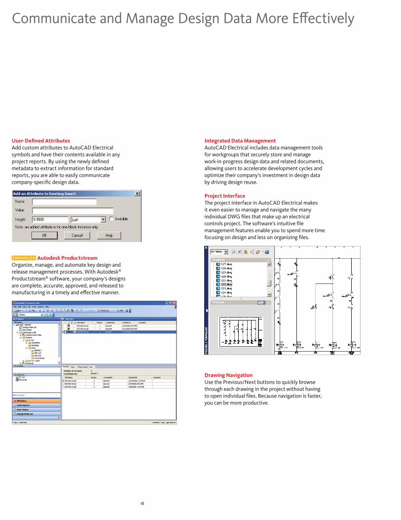
User-Defined AttributesAdd custom attributes to AutoCAD Electrical symbols and have their contents available in any project reports. By using the newly defined metadata to extract information for standard reports, you are able to easily communicate company-specific design data.
Autodesk ProductstreamOrganize, manage, and automate key design and release management processes. With Autodesk® Productstream® software, your company’s designs are complete, accurate, approved, and released to manufacturing in a timely and effective manner.
1�
Communicate and Manage Design Data More Effectively
Integrated Data ManagementAutoCAD Electrical includes data management tools for workgroups that securely store and manage work-in-progress design data and related documents, allowing users to accelerate development cycles and optimize their company’s investment in design data by driving design reuse.
Project InterfaceThe project interface in AutoCAD Electrical makes it even easier to manage and navigate the many individual DWG files that make up an electrical controls project. The software’s intuitive file management features enable you to spend more time focusing on design and less on organizing files.
Drawing NavigationUse the Previous/Next buttons to quickly browse through each drawing in the project without having to open individual files. Because navigation is faster, you can be more productive.

1�
DWF ToolsPublish DWF™ files directly from Autodesk manufacturing design applications, and securely collaborate on 2D and 3D designs with customers, suppliers, planners, and others outside your engineering workgroup. Using the free* Autodesk® Design Review software, team members can digitally review, measure, mark up, and comment on your 2D and 3D designs while protecting your intellectual property. Tight integration with Autodesk manufacturing products allows for accurate communication of design information, including assembly instructions, bills of materials, and finite element analysis (FEA) results without requiring CAD expertise. Autodesk Design Review software automatically tracks comments and their status, and the DWF-based markups can be round-tripped, helping speed the revision process and minimize information loss.
MDI AwareAutoCAD Electrical fully supports the multiple document interface (MDI) standard, which allows you to simultaneously view and edit multiple drawings within a single AutoCAD Electrical session.

*This product is subject to the terms and conditions of the end-user license agreement that accompanies download of this software.
Autodesk, AutoCAD, AutoCAD LT, Autodesk Inventor, AutoLISP, DWF, DWG, DWG (logo), Inventor, Productstream, and Visual LISP are registered trademarks or trademarks of Autodesk, Inc., in the USA and/or other countries. All other brand names, product names, or trademarks belong to their respective holders. Autodesk reserves the right to alter product offerings and specifications at any time without notice, and is not responsible for typographical or graphical errors that may appear in this document. © 2007 Autodesk, Inc. All rights reserved. 000000000000117474
Autodesk Manufacturing Never before have design applications and data management tools come together to simplify the way manufacturers design products and drive them through the manufacturing process. Autodesk provides a complete, interoperable line of industry-leading software integrated with a worldwide network of services and partners. Gain access to technical expertise for implementation, and utilize training and support programs direct from Autodesk to help use your design and data management software more effectively. Software maintenance programs allow you to stay up-to-date with the latest product releases and upgrades for your software. Designed to be deployed incrementally for minimal business disruption, Autodesk tools for manufacturing provide the most effective way to stay ahead of the competition and achieve maximum return on your software investment.
Learn More or PurchaseCreate and revise electrical designs faster than ever with AutoCAD Electrical. For more information, visit www.autodesk.com/autocadelectrical.
For more information on extending the power of your design technology, visit www.autodesk.com/subscription.
For more information on making the most of your software investment, visit www.autodesk.com/consulting.
Purchase AutoCAD Electrical software through your Premier Solutions Provider or Autodesk Authorized Reseller. To locate the reseller nearest you, visit www.autodesk.com/reseller.