auto injector syringe - tutorialdl.racfd.com/auto_injector_syringe_fluent_1dof_16.0.pdf · a fluent...
TRANSCRIPT

1 © 2015 ANSYS, Inc. June 26, 2015
Auto Injector Syringe
A Fluent Dynamic Mesh
1DOF Tutorial

2 © 2015 ANSYS, Inc. June 26, 2015
This tutorial is written with the assumption that
• You have attended the “Introduction to ANSYS Fluent” training course including Design Modeler, Meshing, Fluent and CFD-Post.
• You are familiar with basic geometry creation/import into ANSYS Design Modeler and operations to split geometry.
• You are familiar with assigning size functions and mesh generation in ANSYS Meshing.
• You are familiar with the ANSYS Fluent navigation pane and menu structure.
• The focus of the current tutorial is on the auto-injector application and not on the mechanics of the setup.
– Some steps in the setup and solution procedure will not be shown explicitly.
• Workbench project is attached (note that the included project was saved in R16.0, the current release version of the product). The UDF and this presentation are included in the user_files folder in the Workbench project
Prerequisites

3 © 2015 ANSYS, Inc. June 26, 2015
Problem Description – Axisymmetric Auto-injector
Barrel
Skin (Porous Zone)
Needle Axis
Plunger with virtual spring Needle Tip
Outlet
Wall
Wall
• The 2D geometry is created in Design modeler with appropriate dimensions. • The geometry is decomposed to allow hex meshing
4 © 2015 ANSYS, Inc. June 26, 2015
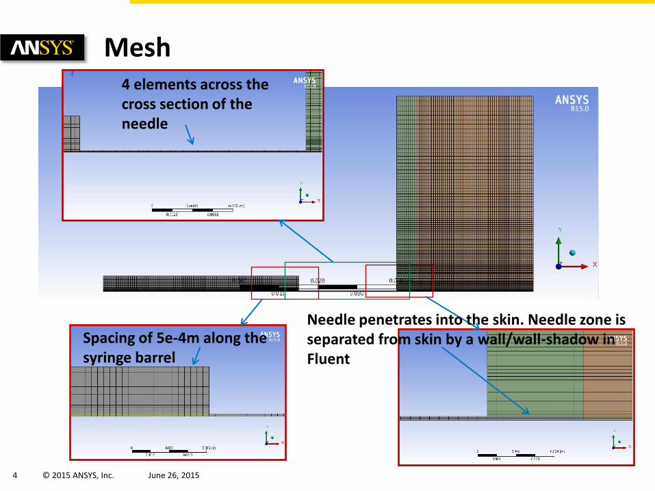
Mesh 4 elements across the cross section of the needle
Spacing of 5e-4m along the syringe barrel
Needle penetrates into the skin. Needle zone is separated from skin by a wall/wall-shadow in Fluent
5 © 2015 ANSYS, Inc. June 26, 2015
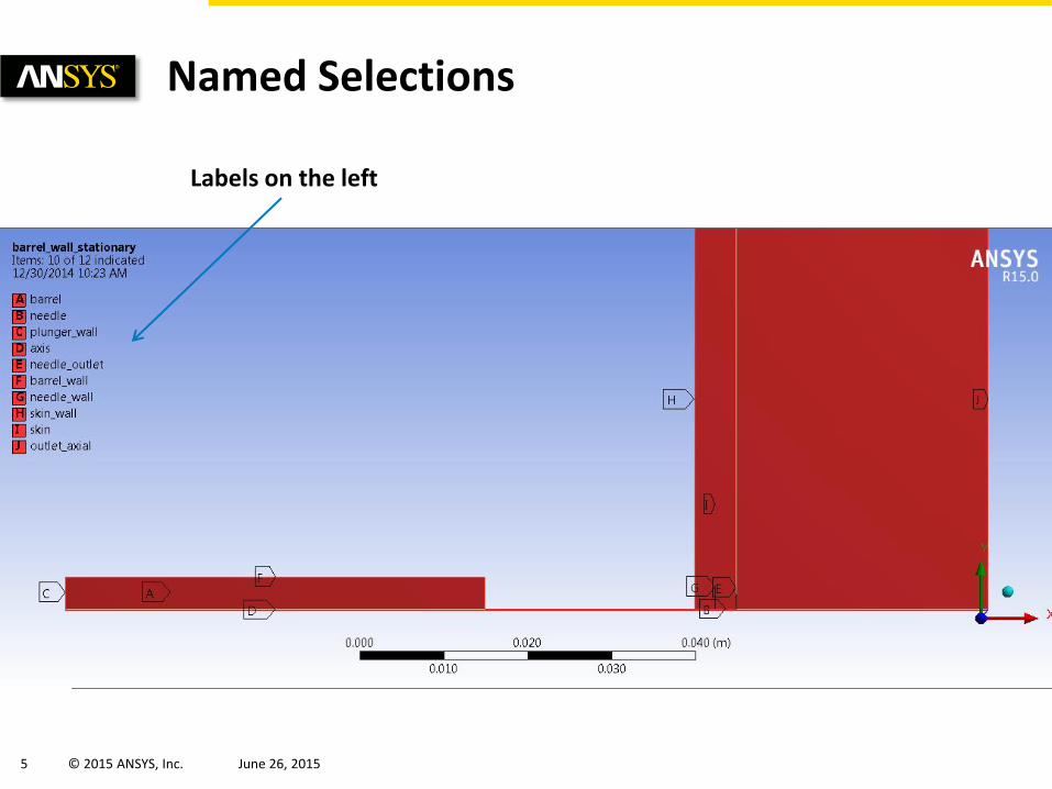
Named Selections
Labels on the left
6 © 2015 ANSYS, Inc. June 26, 2015
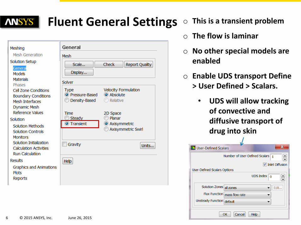
Fluent General Settings o This is a transient problem
o The flow is laminar
o No other special models are enabled
o Enable UDS transport Define > User Defined > Scalars.
• UDS will allow tracking of convective and diffusive transport of drug into skin

7 © 2015 ANSYS, Inc. June 26, 2015
Material Properties o Create Water material
o Enable compressible liquid property for the water. This helps numerically stabilize pressure spikes that can happen when plunger moves and helps convergence.
o Enter appropriate diffusion coefficient of scalar in liquid
o Set the diffusion coefficient to zero if convective transport dominates
8 © 2015 ANSYS, Inc. June 26, 2015
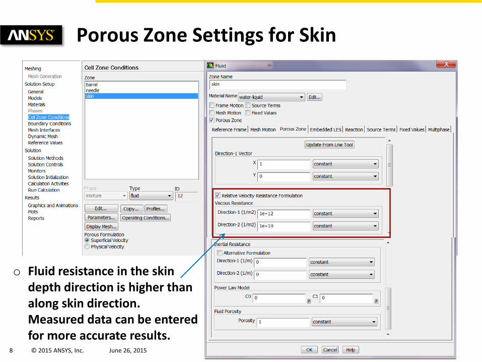
Porous Zone Settings for Skin
o Fluid resistance in the skin depth direction is higher than along skin direction. Measured data can be entered for more accurate results.
9 © 2015 ANSYS, Inc. June 26, 2015
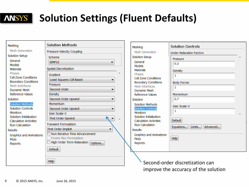
Solution Settings (Fluent Defaults)
Second-order discretization can improve the accuracy of the solution

10 © 2015 ANSYS, Inc. June 26, 2015
Setting Monitors to Track Solution
o Surface monitors can be created to track mass flow rate of drug through fluid outlet, plunger location etc.

11 © 2015 ANSYS, Inc. June 26, 2015
Writing Backup and Solution Files
Enable solution backup
Write CFD-Post files for later processing

12 © 2015 ANSYS, Inc. June 26, 2015
Compiling and Hooking the UDF o Plunger motion is defined via User Define Function (UDF) called rigid_body.c. The UDF
has two functions defined: o Fixed plunger motion o Plunger motion controlled by spring and fluid forces
o A C-compiler is needed to compile the UDF (see Customer Portal for details)

13 © 2015 ANSYS, Inc. June 26, 2015
Initializing the Solution
o Initialize the solution with quiescent conditions
o Patch the User Scalar (UDS) representing the drug into the barrel and needle
14 © 2015 ANSYS, Inc. June 26, 2015
o So far we have described the general settings for the application
o The most critical part of this application is setting up the dynamic mesh algorithm to track the plunger motion
o The following section outlines the settings specific to three situations:
(a) prescribed motion
(b) spring activated – fluid controlled motion of the plunger using Fluent 6DOF approach with solution stabilization and implicit update
(c) spring activated – fluid controlled motion of the plunger using explicit UDF approach (see APPENDIX)
o A “Smoothing” algorithm is used to modify the mesh in the barrel volume as the plunger moves
o For more details, please review material related to “Moving Dynamic Mesh (MDM) algorithm” on the Customer Portal.
Dynamic Mesh Settings

15 © 2015 ANSYS, Inc. June 26, 2015
Fixed Plunger Movement

16 © 2015 ANSYS, Inc. June 26, 2015
Dynamic Mesh Settings
Define “barrel_wall_stationary” as a stationary zone
Diffusion based smoothing is activated, this parameter controls mesh distribution as plunger moves

17 © 2015 ANSYS, Inc. June 26, 2015
Dynamic Mesh Settings
Hook the function “plunger_fixed” to the “plunger_wall” boundary zone under motion attributes tab. Explicitly define the “skin” and “needle” as stationary

18 © 2015 ANSYS, Inc. June 26, 2015
Dynamic Mesh Settings
Deforming zones are defined as a plane to make sure they do not distort as plunger moves
19 © 2015 ANSYS, Inc. June 26, 2015
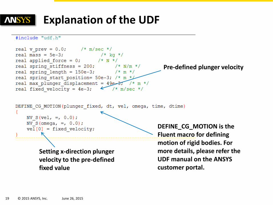
Explanation of the UDF
Pre-defined plunger velocity
DEFINE_CG_MOTION is the Fluent macro for defining motion of rigid bodies. For more details, please refer the UDF manual on the ANSYS customer portal.
Setting x-direction plunger velocity to the pre-defined fixed value
20 © 2015 ANSYS, Inc. June 26, 2015
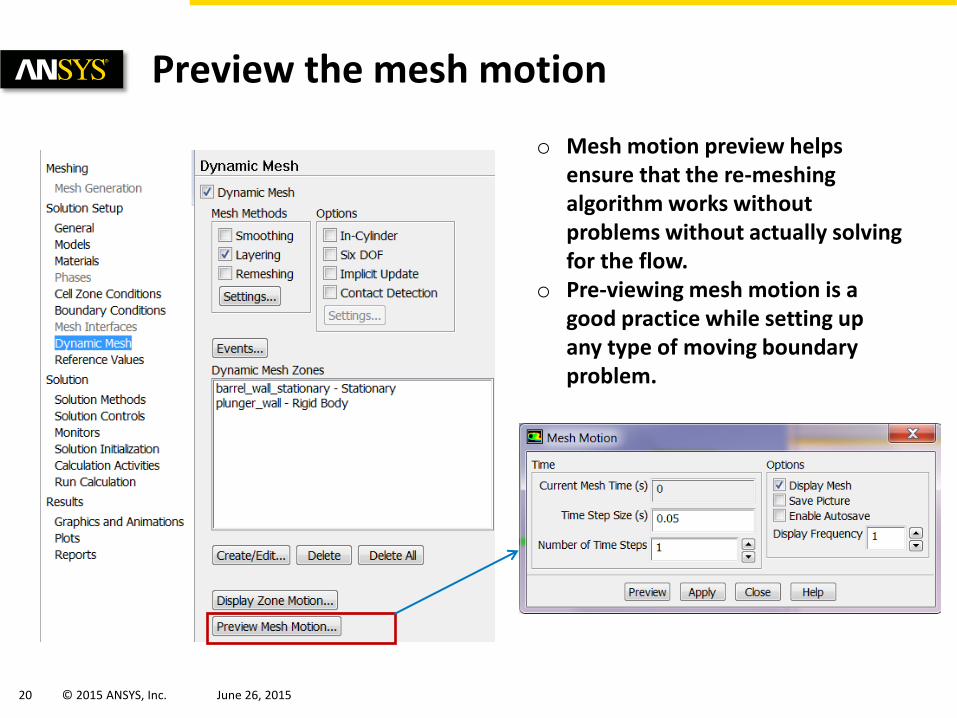
Preview the mesh motion
o Mesh motion preview helps ensure that the re-meshing algorithm works without problems without actually solving for the flow.
o Pre-viewing mesh motion is a good practice while setting up any type of moving boundary problem.
21 © 2015 ANSYS, Inc. June 26, 2015
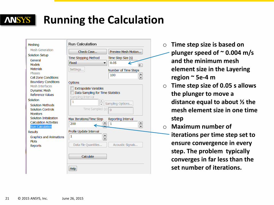
Running the Calculation
o Time step size is based on plunger speed of ~ 0.004 m/s and the minimum mesh element size in the Layering region ~ 5e-4 m
o Time step size of 0.05 s allows the plunger to move a distance equal to about ½ the mesh element size in one time step
o Maximum number of iterations per time step set to ensure convergence in every step. The problem typically converges in far less than the set number of iterations.
22 © 2015 ANSYS, Inc. June 26, 2015
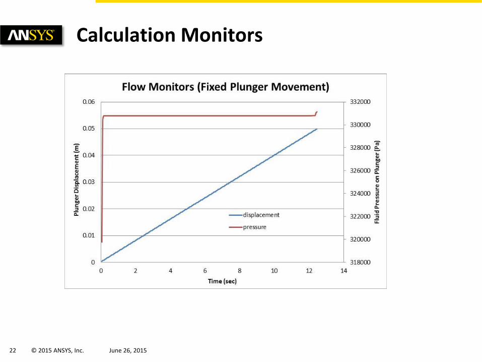
Calculation Monitors

23 © 2015 ANSYS, Inc. June 26, 2015
Drug Injection into Skin (Post processing is done on the saved solution files in CFD-Post)
24 © 2015 ANSYS, Inc. June 26, 2015
Plunger Motion Controlled by Spring and Opposing Fluid Force (using inbuilt 6DOF model)

25 © 2015 ANSYS, Inc. June 26, 2015
6DOF UDF Explained
Mass properties of plunger
Spring Compression
Spring Force applied as external force
o 6DOF model in Fluent calculates fluid forces on plunger and calculates plunger velocity
Restrict plunger motion in all directions except “x”

26 © 2015 ANSYS, Inc. June 26, 2015
Activating 6DOF Model in Fluent
o Implicit update allows us to use much higher time steps. Implicit update adjusts the position of the moving boundary several times within a time step as controlled by the update interval. See next few slides for solution stabilization

27 © 2015 ANSYS, Inc. June 26, 2015
Hook the 6DOF UDF to Control Plunger Motion
Hook the 6DOF UDF
Indicate that this is a 6DOF object
28 © 2015 ANSYS, Inc. June 26, 2015
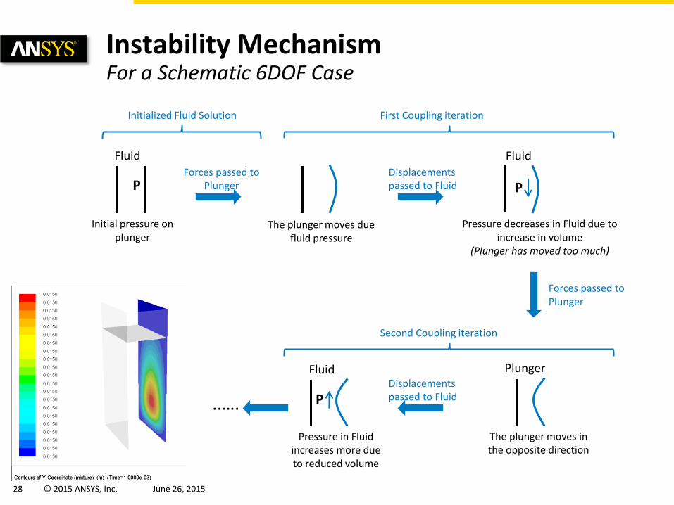
Instability Mechanism For a Schematic 6DOF Case
Fluid
Initial pressure on plunger
Forces passed to Plunger P
The plunger moves due fluid pressure
Fluid
P
Pressure decreases in Fluid due to increase in volume
(Plunger has moved too much)
Plunger
The plunger moves in the opposite direction
Fluid
P
Pressure in Fluid increases more due to reduced volume
First Coupling iteration
Displacements passed to Fluid
Initialized Fluid Solution
Forces passed to Plunger
Second Coupling iteration
Displacements passed to Fluid
..….
29 © 2015 ANSYS, Inc. June 26, 2015
Solution Stabilization
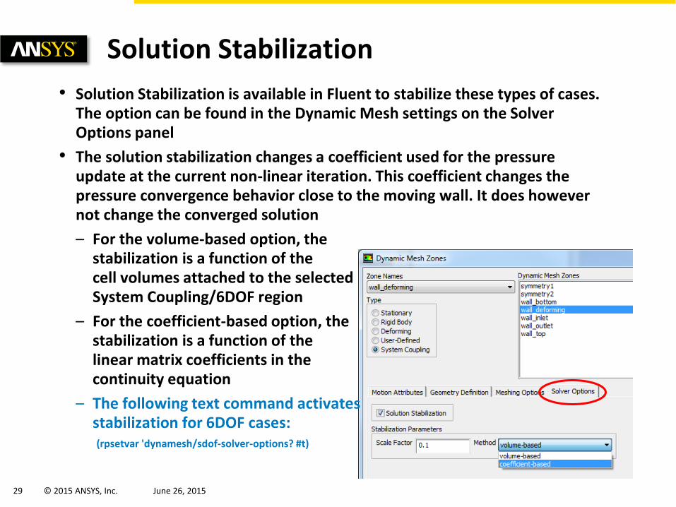
• Solution Stabilization is available in Fluent to stabilize these types of cases. The option can be found in the Dynamic Mesh settings on the Solver Options panel
• The solution stabilization changes a coefficient used for the pressure update at the current non-linear iteration. This coefficient changes the pressure convergence behavior close to the moving wall. It does however not change the converged solution
– For the volume-based option, the stabilization is a function of the cell volumes attached to the selected System Coupling/6DOF region
– For the coefficient-based option, the stabilization is a function of the linear matrix coefficients in the continuity equation
– The following text command activates stabilization for 6DOF cases: (rpsetvar 'dynamesh/sdof-solver-options? #t)

30 © 2015 ANSYS, Inc. June 26, 2015
Solution Stabilization
• From a physical point of view, the stabilization slows down the pressure response in Fluent at the deforming wall
– This means that the pressure doesn’t increase/decrease as fast in Fluent when a new displacement is received
– This “damped” pressure response allows us to move towards the equilibrium, between fluid force and structural deformation, in a controlled way, rather than oscillating around it
• The stabilization has no effect on converged results
• A higher Scale Factor results in more stabilization (i.e. a slower pressure response)
– The appropriate value is case specific
• e.g. for the volume-based method Scale Factors between 0.01 and 1e5 have been used
• If you have small cell volumes you will need a larger Scale Factor
How do we find the correct Scale Factor?
31 © 2015 ANSYS, Inc. June 26, 2015
Solution Stabilization
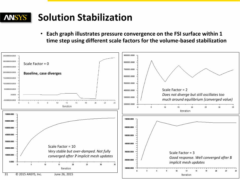
• Each graph illustrates pressure convergence on the FSI surface within 1 time step using different scale factors for the volume-based stabilization
Scale Factor = 0 Baseline, case diverges
Scale Factor = 2 Does not diverge but still oscillates too much around equilibrium (converged value)
Scale Factor = 10 Very stable but over-damped. Not fully converged after 7 implicit mesh updates
Scale Factor = 3 Good response. Well converged after 5 implicit mesh updates
32 © 2015 ANSYS, Inc. June 26, 2015
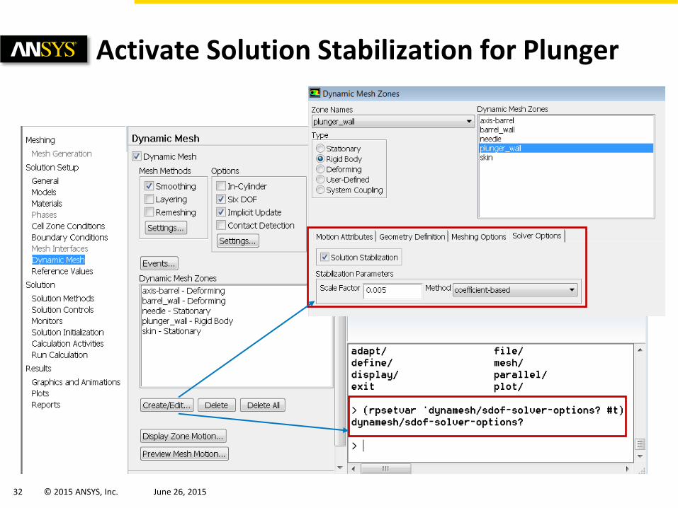
Activate Solution Stabilization for Plunger

33 © 2015 ANSYS, Inc. June 26, 2015
Case Modification
o Case modification strategy is used to ramp up the time step size and ramp down the stabilization factor as the solution runs.
o See next slide for more details of this panel
34 © 2015 ANSYS, Inc. June 26, 2015
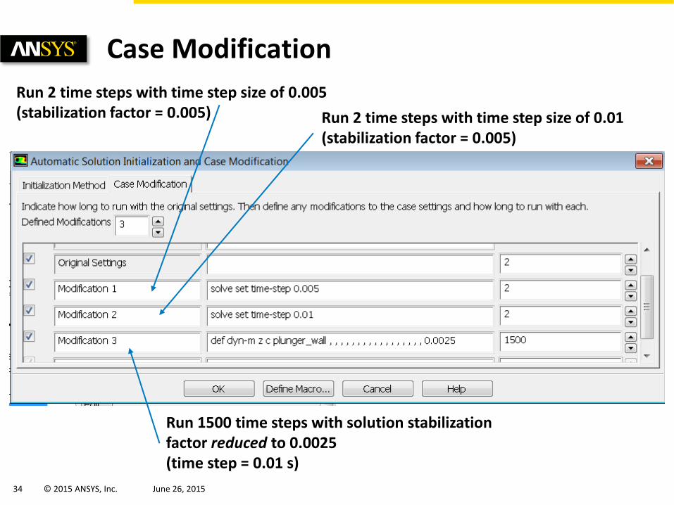
Case Modification
Run 2 time steps with time step size of 0.005 (stabilization factor = 0.005) Run 2 time steps with time step size of 0.01
(stabilization factor = 0.005)
Run 1500 time steps with solution stabilization factor reduced to 0.0025 (time step = 0.01 s)
35 © 2015 ANSYS, Inc. June 26, 2015
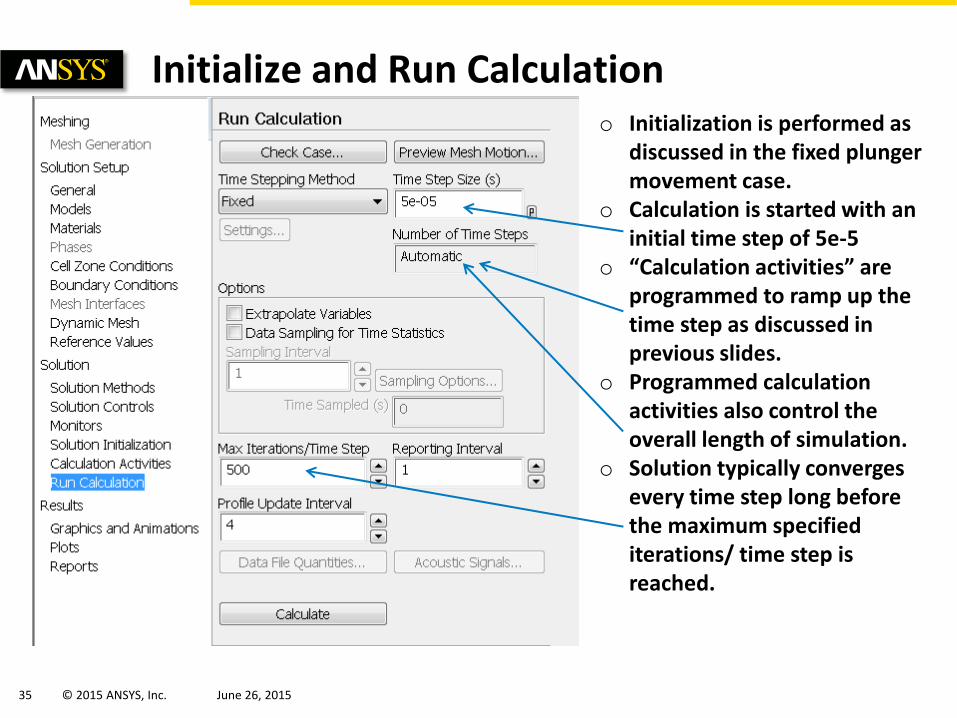
Initialize and Run Calculation o Initialization is performed as
discussed in the fixed plunger movement case.
o Calculation is started with an initial time step of 5e-5
o “Calculation activities” are programmed to ramp up the time step as discussed in previous slides.
o Programmed calculation activities also control the overall length of simulation.
o Solution typically converges every time step long before the maximum specified iterations/ time step is reached.

36 © 2015 ANSYS, Inc. June 26, 2015
Solution Monitors
37 © 2015 ANSYS, Inc. June 26, 2015
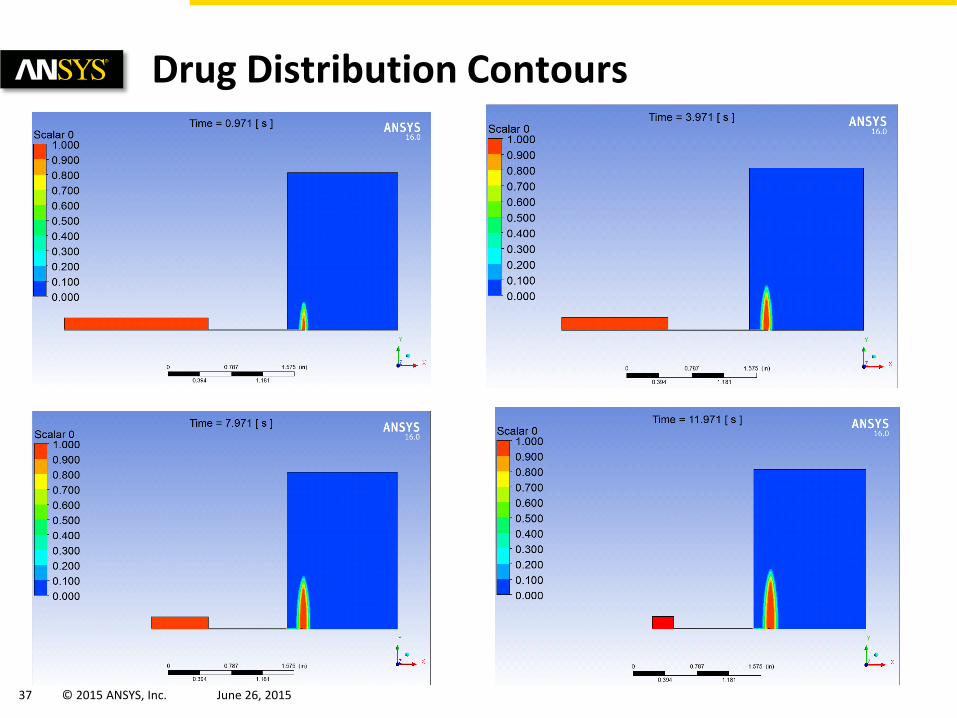
Drug Distribution Contours

38 © 2015 ANSYS, Inc. June 26, 2015
APPENDIX-A
Plunger Motion Controlled by Spring and Opposing Fluid Force (explicit
1DOF UDF)

39 © 2015 ANSYS, Inc. June 26, 2015
UDF for Flow Controlled Motion Explained
o Fluid forces calculated using appropriate macro
o Plunger velocity calculated each time-step using: 𝑽𝒏𝒆𝒘 = 𝑽𝒐𝒍𝒅 +𝑭
𝒎∗ ∆𝒕
where F is the total force including the spring force and m is the mass of the plunger
o In addition to fluid forces, plunger motion is controlled by a spring. Spring stiffness, spring length, and spring start position are inputs to the UDF as shown below.
o Motion is stopped when the plunger reaches the maximum allowable displacement

40 © 2015 ANSYS, Inc. June 26, 2015
UDF explained - 2
Stop plunger motion
Fluent Macro to control rigid body motion
Write data to file

41 © 2015 ANSYS, Inc. June 26, 2015
UDF Explained - 3
Macro to compute fluid forces
Spring displacement
dv = dt * force / mass Total force = externally applied force + spring force + fluid force
Spring force
Vnew = Vold + dv
Apply calculated velocity as new velocity

42 © 2015 ANSYS, Inc. June 26, 2015
Hooking Spring driven plunger function in the Dynamic mesh panel
o No other changes

43 © 2015 ANSYS, Inc. June 26, 2015
Initialize and Run the Calculation o Time step size is based on some
trial and error. 1e-5 is found to be stable for this problem.
o Maximum number of iterations per time step set to ensure convergence in every step. The problem typically converges in far less than the set number of iterations.
o Note that this section with the explicitly written UDF is included for completeness. The inbuilt 6DOF model in Fluent performs the same calculation as a “black box”. There are also some additional stabilization features that can be activated to speed up calculation when using the 6DOF model. See 6DOF section for details.