author's personal copy - swansea...
TRANSCRIPT

This article appeared in a journal published by Elsevier. The attachedcopy is furnished to the author for internal non-commercial researchand education use, including for instruction at the authors institution
and sharing with colleagues.
Other uses, including reproduction and distribution, or selling orlicensing copies, or posting to personal, institutional or third party
websites are prohibited.
In most cases authors are permitted to post their version of thearticle (e.g. in Word or Tex form) to their personal website orinstitutional repository. Authors requiring further information
regarding Elsevier’s archiving and manuscript policies areencouraged to visit:
http://www.elsevier.com/copyright

Author's personal copy
Nuclear Engineering and Design 253 (2012) 192– 199
Contents lists available at SciVerse ScienceDirect
Nuclear Engineering and Design
j ourna l ho me pag e: www.elsev ier .com/ locate /nucengdes
Failure probability study of HTR graphite componentusing microstructure-based model
Suyuan Yua, Xiang Fanga, Haitao Wanga,∗, Chenfeng Lib
a Institute of Nuclear and New Energy Technology, Tsinghua University, Beijing 100084, Chinab Civil and Computational Engineering Centre, College of Engineering, Swansea University, Swansea SA2 8PP, UK
h i g h l i g h t s
� Nuclear graphite mechanical analysis is accomplished.� Both stress analysis and reliability analysis are included.� Various creep models and failure models are used.� The results of all models show good agreement.� The Burchell fracture model is sensitive to stress and neutron dose.
a r t i c l e i n f o
Article history:Received 11 February 2012Received in revised form 27 August 2012Accepted 30 August 2012
a b s t r a c t
Nuclear graphite is widely used as in-core structural material in the high temperature gas-cooled reactors(HTRs). As mechanical properties of graphite change with neutron irradiation and temperature, the reli-ability evaluation of graphite internals of a HTR is commonly accomplished by the finite element analysisusing various constitutive creep models and the following structural failure prediction with introductionof failure models that have essential impact on the final evaluation result. In this paper, a microstructure-based failure model proposed by Burchell in 1996 in conjunction with the finite element code INET-GRA3Dof INET is used to study failure probability of a graphite side reflector design in the pebble-bed HTR duringits entire service life from the microstructural view. The corresponding irradiation-induced creep stressanalysis is carried out using both the UKAEA model and the Kennedy model. H-451 graphite is selectedas material input since its irradiation material data from both macrostructure tests and microstructureobservation is available. The results are compared with those using the macrostructure-based Weibullmodel commonly accepted in the engineering field and consistent trends are observed. Moreover, TheBurchell model leads to the failure probability more sensitive to stress levels than the Weibull model.
© 2012 Elsevier B.V. All rights reserved.
1. Introduction
Nuclear graphite serves as reflector, neutron moderator as wellas major structure material in high temperature gas-cooled reac-tors (HTRs). It is well known that fast neutron irradiation leadsto both dimensional and material property changes of graphite,and that significant creep happens when graphite is stressed undersuch circumstance (Birch and Bacon, 1983; Blackstone, 1977). Forthe in-core graphite components, stresses are generated due tothe non-uniformity of temperature and irradiation (Burchell andSnead, 2007; Engle and Kelly, 1984). Considering that high stressconcentration can significantly influence the structural integrityand service lives of graphite components, it is essential thatstress distributions of graphite components are obtained and then
∗ Corresponding author. Tel.: +86 10 62797882.E-mail address: [email protected] (H. Wang).
properly evaluated. Over the last several decades, various consti-tutive creep models and failure models have been proposed anddeveloped (Kelly, 1982). Such models are commonly integratedinto the finite element code via user subroutines in order to carryout irradiation stress analysis and reliability evaluation of graphitecomponents.
Numerical evaluation of an irradiated graphite componentusing the finite element modeling technique consists of twosteps, namely (1) irradiation-induced stress analysis: by establish-ing a three-dimensional graphite model, finite element meshing,inputting graphite properties (Young’s modulus, CTE, thermal con-ductivity, dimensional change, etc.) as functions of both irradiationand temperature, generating creep parameters according to creepmodels, and applying boundary conditions (including temperaturedistribution and neutron irradiation distribution during the entireservice life), a finite element analysis is carried out and stress distri-butions are readily obtained (Tsang and Marsden, 2005, 2007; Berreet al., 2008). (2) Reliability analysis: stresses at all integration points
0029-5493/$ – see front matter © 2012 Elsevier B.V. All rights reserved.http://dx.doi.org/10.1016/j.nucengdes.2012.08.019

Author's personal copy
S. Yu et al. / Nuclear Engineering and Design 253 (2012) 192– 199 193
of the finite element model are used as input following certaindeterministic or probabilistic failure model to evaluate structuralintegrity at each time point (e.g., each year) of the service life(Schubert et al., 1991; Oku and Ishihara, 2004).
There are several creep models available for the irradiation-induced stress analysis, like the UKAEA model (Kelly andBrocklehurst, 1977) and the Kennedy model (Kennedy et al.,1980), which establish a relationship between creep and otherirradiation properties of graphite such as elastic modulus anddimensional information. These models have been verified by irra-diation tests of stressed nuclear graphite specimens and goodagreement was reported (Kelly and Burchell, 1994a). For the failuremodels, both deterministic and probabilistic models are acceptedin the engineering standards and codes. The probabilistic methodis commonly regarded as a more suitable tool to evaluate brit-tle materials like graphite. As an example of application, one canfind the Weibull model used in the German HTR code draft KTA-3232 (KTA, 1992) to generate a value of failure probability forgraphite components in HTRs. Parameters of the Weibull modelcome from the tensile tests of graphite specimens, which showdirect but macro-structural information of failure. On the otherhand, a microstructure-based failure model initially proposed byBurchell in 1996 attributes structural failure of stressed graphite tothe microstructural fracture-induced failure of graphite particles.This model establishes a mechanism to evaluate structural integrityof graphite components from the microstructural view. Comparedwith frequent studies on the failure probability of graphite usingthe Weibull model (Schubert et al., 1991; Wang and Yu, 2008; Fanget al., 2011), there is little report on the application of the Burchellmodel to evaluate pebble-bed HTR graphite components.
In the present paper, the Burchell model is applied in con-junction with the finite element code INET-GRA3D of INET tonumerically study the failure probability of pebble-bed HTRgraphite components from a microstructural view during the entirereactor service life. The idea of microstructural fracture-inducedparticle failure mode is extended to establish a failure mecha-nism at each integration point of the finite element model, therebymaking it possible to evaluate failure probability of a graphitecomponent with arbitrary shape. A candidate design of graphiteside reflector in the pebble-bed HTR is selected to develop athree-dimensional model to be investigated. The following sec-tions are organized as follows. In Section 2, the constitutive law ofirradiation-induced creep of graphite is briefly reviewed and sev-eral classical creep models are summarized. In Section 3, detailedformula of probabilistic failure models including macrostructure-based Weibull model and microstructure-based Burchell model arelisted, with a focus on their extension to be combined with the finiteelement modeling technique. In Section 4, a three-dimensionalfinite element model of one candidate design of the pebble-bed HTRgraphite side reflector is established and analyzed using differentcreep model/failure model combinations. Stress distributions andthe corresponding failure probabilities along with the entire reac-tor service life are calculated and compared among creep/failuremodels. In Section 5, conclusions are given.
2. Review of the constitutive creep law of irradiatedgraphite and creep models
2.1. Constitutive law of irradiate graphite
The constitutive law for nuclear graphite under high tempera-ture and fast neutron irradiation condition is (Tsang and Marsden,2008; Wang and Yu, 2008)
� = D(T, �)εE = D(T, �)(ε − εT − εR − εC ) (1)
where � is the stress tensor, D(T, �) is the elastic matrix as a func-tion of temperature T and neutron dose � . The total strain tensor εis composed of the elastic strain εE, thermal strain εT, irradiation-induced strain εR, and creep strain εC. Generally speaking, theirradiation-induced creep strain is divided into two phases: theprimary creep strain εPC and the secondary creep strain εSC. εPC
is commonly approximated as �/E0, and εSC equals to k�� , whereE0 is the Young’s modulus of virgin graphite and k is the secondarycreep coefficient. Therefore, εC in Eq. (1) is expressed as (Yao et al.,2007)
εC = εPC + εSC = �
E0+ k��. (2)
2.2. Creep models for stress analysis
The secondary creep coefficient k is a key factor in Eq. (2) as thevalue of k changes along with variations of temperature, neutrondose and stress loaded. In the classical visco-elastic model, k comesfrom the test data of irradiated graphite specimens under tensileor compressive load. However, such irradiation test of stressedgraphite is very complicated, time-consuming and very limiteddata are available at the end. In order to overcome such drawback,several creep models such as the UKAEA model and Kennedy modelhave been developed to predict the creep according to the test dataof other more easily obtained properties under irradiation.
In the UKAEA model, Young’s modulus is selected as the substi-tute of k. k at a neutron dose � can be written as a function form as(Kelly and Brocklehurst, 1977)
k(�) = kP
[E∗
E(�)
]= kPS(�)−1, (3)
where kP is the secondary creep coefficient in some specific region,E* is the corresponding Young’s modulus. S is a structural factor.The creep strain in Eq. (2) by UKAEA model is rewritten as,
εC = εPC + εSC = �
E0+ kP
∫ �
0
�S(�)−1d�. (4)
In the Kennedy model, the data of the percentage volume change�V/V is applied instead of the data of k. k is rewritten as (Kennedyet al., 1980)
k(�) = kP
[1 − �
(�V/V)(T, �)(�V/V)m
]. (5)
�V/V is a function of temperature T and neutron dose � (�V/V)m
is the maximum volume shrinking of the graphite, and � is empir-ical constant, � = 0.75. The creep strain in Eq. (2) is rewritten byKennedy model as
εC = εPC + εSC = �
E0+ kP
∫ �
0
�
[1 − �
(�V/V)(�)(�V/V)m
]d�. (6)
3. Probabilistic failure models
According to the finite element modeling, a graphite compo-nent can be divided into many integration points in the calculation.Each integration point refers to a calculated stress level and thuspossesses an independent failure probability according to the prob-abilistic failure models. The total failure probability of a graphitecomponent is a composite of all integration points’ failure prob-abilities. For the Weibull model and Burchell fracture model, theseeking law of one integration point’s failure probability as wellas the synthesis artifice of the total failure probability are totallydifferent. In addition, parameters of the two models have differentphysical meanings.
Author's personal copy
194 S. Yu et al. / Nuclear Engineering and Design 253 (2012) 192– 199
3.1. Weibull model
Parameters in the Weibull model are mainly obtained from theexperimental test of unirradiated graphite specimens. To integratethis model to the finite element method, the probability densityfunction f(x) at each integration point is determined by the fol-lowing two-parameter Weibull distribution (KTA, 1992; Yu et al.,2004):
f (x) =(
x
Sc
)m−1 m
Scexp
[−(
x
Sc
)m]
; x > 0 (7)
where m is a shape parameter, Sc is characteristic strength value.Both m and Sc arise from the fitting experimental curves. If � repre-sents the variable x in Eq. (7), failure probability Pi at an integrationpoint can be designated as
Pi =∫ �
0
f (x)dx = 1 − exp
[−(
�
Sc
)m]
, (8)
The survival probability is then deduced as,
1 − Pi = exp
[−(
�
Sc
)m]
. (9)
The survival probability of the graphite component is
Ps = exp
{−∑
i
[(�
Sc
)m
× Vi
V
]}, (10)
with Vi defined as the representative volume of the integration
point and V the total volume of the graphite component, V =∑
i
Vi.
The failure probability of the graphite component is then expressedas (Yu et al., 2004),
Ptot = 1 − Ps = 1 − exp
{−∑
i
[(�
Sc
)m
× Vi
V
]}. (11)
3.2. Burchell fracture model
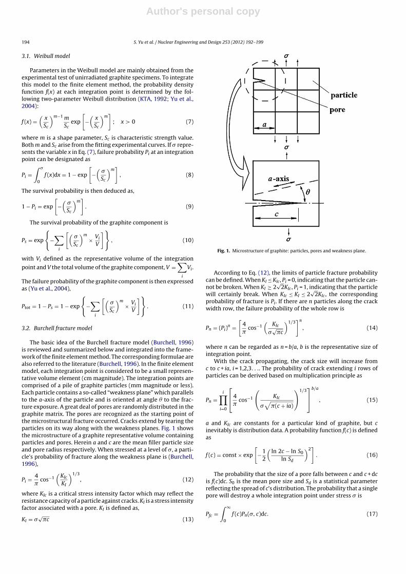
The basic idea of the Burchell fracture model (Burchell, 1996)is reviewed and summarized below and integrated into the frame-work of the finite element method. The corresponding formulae arealso referred to the literature (Burchell, 1996). In the finite elementmodel, each integration point is considered to be a small represen-tative volume element (cm magnitude). The integration points arecomprised of a pile of graphite particles (mm magnitude or less).Each particle contains a so-called “weakness plane” which parallelsto the a-axis of the particle and is oriented at angle � to the frac-ture exposure. A great deal of pores are randomly distributed in thegraphite matrix. The pores are recognized as the starting point ofthe microstructural fracture occurred. Cracks extend by tearing theparticles on its way along with the weakness planes. Fig. 1 showsthe microstructure of a graphite representative volume containingparticles and pores. Herein a and c are the mean filler particle sizeand pore radius respectively. When stressed at a level of �, a parti-cle’s probability of fracture along the weakness plane is (Burchell,1996),
Pi = 4�
cos−1(
KIc
KI
)1/3, (12)
where KIc is a critical stress intensity factor which may reflect theresistance capacity of a particle against cracks. KI is a stress intensityfactor associated with a pore. KI is defined as,
KI = �√
�c (13)
Fig. 1. Microstructure of graphite: particles, pores and weakness plane.
According to Eq. (12), the limits of particle fracture probabilitycan be defined. When KI ≤ KIc, Pi = 0, indicating that the particle can-not be broken. When KI ≥ 2
√2KIc , Pi = 1, indicating that the particle
will certainly break. When KIc ≤ KI ≤ 2√
2KIc , the correspondingprobability of fracture is Pi. If there are n particles along the crackwidth row, the failure probability of the whole row is
Pn = (Pi)n =[
4�
cos−1(
KIc
�√
�c
)1/3]n
, (14)
where n can be regarded as n = b/a, b is the representative size ofintegration point.
With the crack propagating, the crack size will increase fromc to c + ia, i = 1,2,3. . .. The probability of crack extending i rows ofparticles can be derived based on multiplication principle as
Pn =i∏
i=0
⎡⎣ 4�
cos−1
(KIc
�√
�(c + ia)
)1/3⎤⎦b/a
, (15)
a and KIc are constants for a particular kind of graphite, but cinevitably is distribution data. A probability function f(c) is definedas
f (c) = const × exp
[−1
2
(ln 2c − ln S0
ln Sd
)2]
. (16)
The probability that the size of a pore falls between c and c + dcis f(c)dc. S0 is the mean pore size and Sd is a statistical parameterreflecting the spread of c’s distribution. The probability that a singlepore will destroy a whole integration point under stress � is
Pfc =∫ ∞
0
f (c)Pn(�, c)dc. (17)

Author's personal copy
S. Yu et al. / Nuclear Engineering and Design 253 (2012) 192– 199 195
Table 1Parameters for creep models.
Case number 1 2
Primary creep ratio Same as elastic (<0.5) Same as elastic (<0.5)Secondary creep ratio Same as elastic (<0.5) 0.5
The survival probability of the integration point is thenexpressed as,
Pfs = (1 − Pfc)2 =[
1 −∫ ∞
0
f (c)Pn(�, c)dc
]2
(18)
As each pore has two sides, there is a square in the right side of Eq.(18).
If N is defined as the number of pores per unit volume and V isvolume of the integration point, NV is the amount of pores in thepart. The total fracture probability of the part is
Pf tot = 1 − PNVs = 1 −
[1 −∫ ∞
0
f (c)Pn(�, c)dc
]2NV
. (19)
The graphite component possesses many integrals whose vol-ume and stress levels vary significantly. Therefore the survivalprobability of the component is (Ishihara et al., 2001)
Ps =∏
j
[1 −∫ ∞
0
f (c)Pn(�(j), c)dc
]2NV(j)
. (20)
The total fracture probability of the graphite component is
Ptot = 1 − Ps = 1 −∏
j
[1 −∫ ∞
0
f (c)Pn(�(j), c)dc
]2NV(j)
. (21)
4. Numerical results
In the following, a three-dimensional finite element model isestablished according to a candidate design of the pebble-bedHTR graphite side reflector. Nuclear graphite H-451 is selectedas material input since its irradiation material data from bothmacrostructure tests and microstructure observation is available.Stress analysis is carried out using both the UKAEA model and theKennedy model in order to obtain stress distributions of the entiregraphite component during its service life. The corresponding fail-ure probability is deduced according to the microstructure-basedBurchell fracture model, and the results are compared with thosefrom the Weibull model.
4.1. Finite element model and material data
The finite element is carried out using the three-dimensionalfinite element code INET-GRA3D developed by INET. The code isbased on user subroutines of the commercial software MSC.MARC.Algorithms for various creep models and failure models are inte-grated into the code. Besides, some uncertainties must be taken intoconsideration in the analysis (Kelly and Burchell, 1994b). Two casesof different creep ratio are considered. The primary creep ratio mustbe the same as the elastic ratio (<0.5), while the secondary creepratio is either the same as the elastic ratio (<0.5) or the same asthe plastic case (=0.5). The two cases and parameters are listed inTable 1. Both cases are calculated using various creep models andfailure models.
Fig. 2. 1/4 model of a candidate design of graphite side reflector in pebble-bed HTR.
A modified equivalent stress �eq is used to evaluate service lifeof graphite component in reliability analysis defined as (Schubertet al., 1991),
�eq =√
�̄21 + �̄2
2 + �̄23 − 2( �̄1�̄2 + �̄2�̄3 + �̄3�̄1)
where is Poisson’s ratio, �̄i (i = 1, 2, 3) are modified principalstresses which are defined as:
�̄i =
⎧⎨⎩�i, �i ≥ 0
�i�T
�C, �i < 0
�i (i = 1, 2, 3) are principal stresses, �T and �C are the tensile andcompressive strength, respectively.
Fig. 2 shows a 1/4 model with symmetric conditions of a candi-date design of the pebble-bed HTR graphite side reflector. There aretwo circular holes, one for the control rod and the other serves ashelium path. The left side of the brick faces to reactor core while theright side neighbors the peripheral carbon bricks. Fig. 3 shows thetemperature distribution at the end of 30 years’ service life (EOL).The temperature of the core side is 450 ◦C while the other side is280 ◦C. There exists a large temperature gradient around the controlrod hole. The maximum fast neutron dose at the core side reaches1 × 1022 n cm−2 (EDN) at EOL, and decreases in a radial directiontoward the outside, following an exponential law.
Young’s modulus is the key information in the UKAEA model asthe Young’s modulus is selected as the substitute of the secondarycreep coefficient. Fig. 4 shows the Young’s modulus’ curves for H-451 graphite versus neutron dose at 600 ◦C (Burchell, 2008). The
Fig. 3. Temperature distribution at EOL (unit: ◦C).

Author's personal copy
196 S. Yu et al. / Nuclear Engineering and Design 253 (2012) 192– 199
Fig. 4. Young’s modulus development for H-451 at 600 ◦C.
Young’s modulus sustains growth until 8 × 10²¹ n cm−2 (EDN), fol-lowed by a constant phase and a re-increasing phase. The Young’smodulus curve begins to decline after about 13 × 1021 n cm−2
(EDN).The Kennedy model uses the dimensional change as the substi-
tute of the secondary creep coefficient. Fig. 5 shows the a-directionand c-direction percentage dimensional change for H-451 graphiteversus neutron dose at 600 ◦C and 900 ◦C (Burchell, 2008). Theshrinkage in c-direction is always smaller than the shrinkage ina-direction, indicating the expansion in c-direction will be muchgreater. The extreme shrinkage value at 600 ◦C is greater thanthe value at 900 ◦C. With the temperature rising, the initiation ofshrinking and expanding occurs earlier, indicating that the graphitecomponent will degrade sooner in high temperature.
For the failure model, parameters of the Burchell model comefrom the microstructure information of both unirradiated andirradiated graphite, while parameters of the Weibull model arecommonly deduced from the tensile test data of unirradiatedgraphite. Table 2 lists major parameters of H-451 graphite for theBurchell model (Burchell, 1996). In order to make comparison,parameters of H-451 graphite for the Weibull model are calculated
Fig. 5. Dimensional change for H-451 at 600 ◦C and 900 ◦C.
Table 2Input parameters of H-451 graphite for two failure models.
Parameter Value
Burchell modelMean particle size, a (�m) 500Bulk density, (g/cm3) 1.79Mean pore size, S0 (�m) 42Statistical parameter, Sd 1.9Mean pore area, Pa (�m2) 700Number of pores per m3, N (m−3) 2.97 × 10⁸
Specimen volume, V (m3) 3.17 × 10⁻⁶
Specimen breadth, b (mm) 8.44Particle critical stress intensity factor, KIc (MPa m1/2) 0.285
Weibull modelWeibull parameter, m 9.97Weibull parameter, Sc (MPa) 16.86
by fitting the probabilistic test data (Burchell, 1996) using the leastsquares fitting method and appended in Table 2.
Fig. 6 shows the prediction of the two models against the testresult. Good agreement is observed. The maximum predicted devi-ation of both models is about 1 MPa. The experimental curve andtwo predicted curves are at the nearest at the mean strength point(50% failure probability, 16–17 MPa). On the left-half of Fig. 6, thefailure probability of Weibull model prediction is the maximum,while failure probability of Burchell model prediction is the mini-mum. On the right-half, the state is just the opposite. That indicatesthe curve of Burchell model is “steeper” and more sensitive to thestress than Weibull model in a stress range near the mean strengthpoint. When the stress changes, the variation of failure probabilityby Burchell model is expected to be greater than the variation byWeibull model.
In the presence of the fast neutron irradiation, most parame-ters in Table 2 change, except mean particle size a, bulk density and Statistical Parameter Sd. KIc increases rapidly in the early irra-diation, and reaches a saturation value of 0.42 MPa m1/2 at dose of1020 n cm−2 (EDN). Specimen volume V and breadth b are real-timeobtained from FEM calculation. The neutron dose dependency ofmean pore size S0, mean pore area Pa, pore density N and porosityare figured in Fig. 7 (Burchell, 1996). All modified parameters areadopted in Burchell fracture model reliability analysis.
Fig. 6. Prediction and experimental results of tensile strength of H-451 graphite.
Author's personal copy
S. Yu et al. / Nuclear Engineering and Design 253 (2012) 192– 199 197
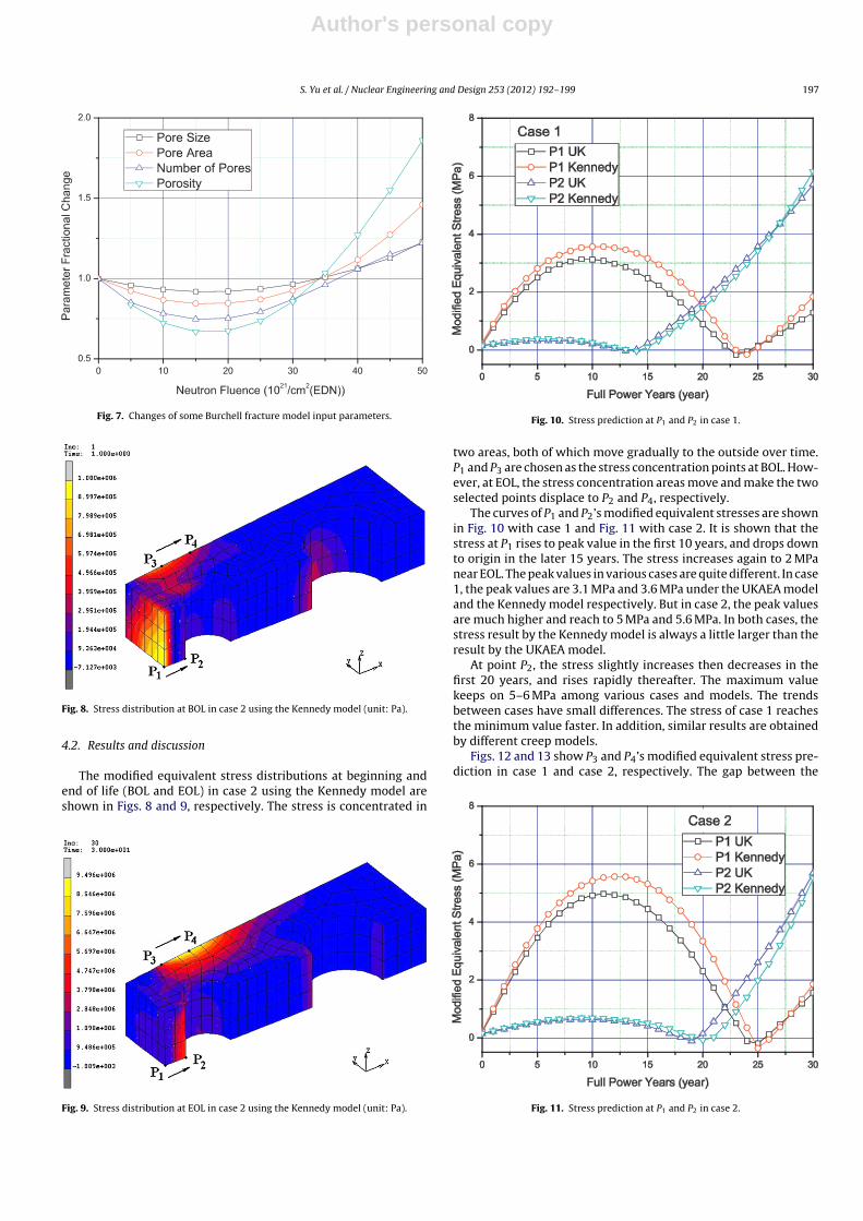
Fig. 7. Changes of some Burchell fracture model input parameters.
Fig. 8. Stress distribution at BOL in case 2 using the Kennedy model (unit: Pa).
4.2. Results and discussion
The modified equivalent stress distributions at beginning andend of life (BOL and EOL) in case 2 using the Kennedy model areshown in Figs. 8 and 9, respectively. The stress is concentrated in
Fig. 9. Stress distribution at EOL in case 2 using the Kennedy model (unit: Pa).
Fig. 10. Stress prediction at P1 and P2 in case 1.
two areas, both of which move gradually to the outside over time.P1 and P3 are chosen as the stress concentration points at BOL. How-ever, at EOL, the stress concentration areas move and make the twoselected points displace to P2 and P4, respectively.
The curves of P1 and P2’s modified equivalent stresses are shownin Fig. 10 with case 1 and Fig. 11 with case 2. It is shown that thestress at P1 rises to peak value in the first 10 years, and drops downto origin in the later 15 years. The stress increases again to 2 MPanear EOL. The peak values in various cases are quite different. In case1, the peak values are 3.1 MPa and 3.6 MPa under the UKAEA modeland the Kennedy model respectively. But in case 2, the peak valuesare much higher and reach to 5 MPa and 5.6 MPa. In both cases, thestress result by the Kennedy model is always a little larger than theresult by the UKAEA model.
At point P2, the stress slightly increases then decreases in thefirst 20 years, and rises rapidly thereafter. The maximum valuekeeps on 5–6 MPa among various cases and models. The trendsbetween cases have small differences. The stress of case 1 reachesthe minimum value faster. In addition, similar results are obtainedby different creep models.
Figs. 12 and 13 show P3 and P4’s modified equivalent stress pre-diction in case 1 and case 2, respectively. The gap between the
Fig. 11. Stress prediction at P1 and P2 in case 2.

Author's personal copy
198 S. Yu et al. / Nuclear Engineering and Design 253 (2012) 192– 199
Fig. 12. Stress prediction at P3 and P4 in case 1.
predicted stress curves in the two cases is negligible, indicatingthat the choice of secondary creep ratio affects the stresses at P3and P4 very little in the chosen temperature and irradiation range.The stresses at both points rise simultaneously and rapidly in thefirst 20 years, but diverge thereafter. The stress at P3 falls while thestress at P4 keeps on increasing throughout the life time except atEOL. The peak values at P3 appear near 20 service year and reach7 MPa and 7.9 MPa under the UKAEA model and the Kennedy model.The peak values at P4 under various models appear near EOL andreach 8.6 MPa and 9.7 MPa. The stress result by the Kennedy modelis also larger than the result by the UKAEA model with a largestdeviation of 1.1 MPa.
The failure probability reflects the structural integrity and lifesensitivity of graphite component. As the most important HTR corestructural component, the graphite side reflector belongs to the firstStructural Reliability Class (SRC-I) in the German HTR code draftKTA-3232 (KTA, 1992) with the allowable value of failure proba-bility derived from stress distribution to be 10−4. The predictedfailure probabilities of various creep and failure models in case 1are shown in Fig. 14. The trends of all curves are the same althoughthere are differences on the specific values. The failure probabilityincreases continually in the whole lifetime except near EOL. Theresults obtained with Weibull distribution model reaches 1 × 10⁻⁷
Fig. 13. Stress prediction at P3 and P4 in case 2.
Fig. 14. Failure probability prediction in case 1.
to 1.2 × 10⁻⁷. The failure probability calculated with stress result ofKennedy model is greater since the Kennedy model gives greaterstress result than the UKAEA model.
It is clearly shown in Fig. 14 that the failure probability obtainedwith Burchell model changes much faster. The results of Burchellmodel calculated with Kennedy model stress is an order of magni-tude greater than the results calculated with UKAEA model stress.That indicates the Burchell fracture model is more sensitive tostress and neutron dose than the Weibull model. When the stress orneutron dose change, the changing rate of the Burchell model resultis obviously faster than the Weibull model result. However, in theselected temperature and irradiation range, the failure probabil-ity values of both models are always comparable. This observationis consistent with the previous discussion in Section 4.1. The fail-ure probability obtained with Burchell model is much lower thanthat of the Weibull model at BOL but increases rapidly and reachespeak value near 25 years, and the value is close to (calculated withUKAEA model) or even exceed (calculated with Kennedy model)the results of Weibull model.
Fig. 15 shows the failure probability curves in case 2. It is shownthat the results in case 1 and case 2 are very close. The maximumfailure probability appears near 25 years of service life. The peakvalue is 3 × 10⁻⁸ to 1 × 10⁻⁷ for Weibull model, and 5 × 10⁻⁸ to1 × 10−6 for Burchell model.
Fig. 15. Failure probability prediction in case 2.
Author's personal copy
S. Yu et al. / Nuclear Engineering and Design 253 (2012) 192– 199 199
5. Conclusions
Nuclear graphite is the key in-core structural material of thepebble bed HTRs. When subjected to high temperature as wellas fast neutron irradiation, significant dimensional and propertychanges happen to the graphite, and creep occurs with load. Thefinite element method in conjunction with constitutive creep lawsis commonly used to study structural integrity of the graphitecomponents taking into account the above-mentioned irradiationbehavior of graphite. Among numerous failure models developedto evaluate graphite components, the Burchell model gives a prob-abilistic prediction based on the microstructural characteristics ofgraphite. In this paper, the Burchell model has been integrated intothe framework of the finite element code INET-GRA3D of INET andused to study failure probability of a pebble-bed HTR graphite com-ponent from the microstructural view. Both the UKAEA model andthe Kennedy model have been adopted to generate creep in thestress analysis. H-451 graphite is selected as material input due toits available data from both macro- and microstructural views. Theresults have been summarized and compared with those using theWeibull model commonly accepted in the engineering field.
It is clearly shown that numerical results of the failure prob-abilities arising from the two failure models are in satisfactoryagreement in the developing trends although there are discrep-ancies on the specific values. None of the predictions exceeds thecriteria requirement 10−4. In addition, the Burchell model leads tothe failure probability more sensitive to the stress and neutron dosethan that of the Weibull model, indicating that stress concentra-tions play an important role in the Burchell model. This conclusionis consistent with the fact that Burchell focuses on the contribu-tion of the peak stresses rather than the average contributions ofall stresses as the Weibull model does.
Acknowledgement
Financial supports for the project from the National Natural Sci-ence Foundation of China, under grant no. 10602029 and ResearchFund for the Doctoral Program under grant no. 041588008 aregratefully acknowledged. The authors would also like to thank theRoyal Academy of Engineering, for its support through the ResearchExchanges with China and India Award.
References
Berre, C., Fok, S.L., Marsden, B.J., Mummery, P.M., Marrow, T.J., Neighbour, G.B., 2008.Microstructural modelling of nuclear graphite using multi-phase models. J. Nucl.Mater. 380 (1-3), 46–58.
Birch, M., Bacon, D.J., 1983. The effect of fast-neutron irradiation on the compressivestress–strain relationships of graphite. Carbon 21 (5), 491–496.
Blackstone, R., 1977. Radiation creep of graphite: an introduction. J. Nucl. Mater. 65,72–78.
Burchell, T.D., 1996. A microstructurally based fracture model for polygranulargraphites. Carbon 34 (3), 297–316.
Burchell, T.D., Snead, L.L., 2007. The effect of neutron irradiation damage on theproperties of grade NBG-10 graphite. J. Nucl. Mater. 371 (1-3), 18–27.
Burchell, T.D., 2008. Irradiation induced creep behavior of H-451 graphite. J. Nucl.Mater. 381 (1–2), 46–54.
Engle, G.B., Kelly, B.T., 1984. Radiation damage of graphite in fission and fusionreactor systems. J. Nucl. Mater. 122 (1–3), 122–129.
Fang, X., et al., 2011. The various creep models for irradiation behavior of nucleargraphite. Nucl. Eng. Des., http://dx.doi.org/10.1016/j.nucengdes.2011.09.024
Ishihara, M., Takahashi, T., Hanawa, S., 2001. Applicability of Advanced DesignMethod of Graphite Components by Microstructure-Based Brittle FractureModel. SmiRT 16, Washington DC. Paper # 1920.
Kelly, B.T., Brocklehurst, J.E., 1977. UKAEA reactor group studies of irradiationinduced creep in graphite. J. Nucl. Mater. 65 (1), 79–85.
Kelly, B.T., 1982. Graphite – the most fascinating nuclear material. Carbon 20 (1),2–11.
Kelly, B.T., Burchell, T.D., 1994a. The analysis of irradiation creep experiments onnuclear reactor graphite. Carbon 32 (1), 119–125.
Kelly, B.T., Burchell, T.D., 1994b. Structure-related property changes in polycrys-talline graphite under neutron irradiation. Carbon 32 (3), 499–505.
Kennedy, C.R., Eatherly, W.P., Senn, R.L., 1980. Compressive creep characteristicsof graphite under irradiation. In: 33rd Pacific Coast Regional Meeting of theAmerican Ceramic Society, San Francisco, October 26–29.
KTA 3232 Keramische Einbauten in HTR-Reacktordruckbehälten. Sicherheitstech-nische Regel des KTA, 1992.
Oku, T., Ishihara, M., 2004. Lifetime evaluation of graphite components for HTGRs.Nucl. Eng. Des. 227 (2), 209–217.
Schubert, F., Nickel, H., Breitbach, G., 1991. Structural design criteria for HTR-a sum-mary report. Nucl. Eng. Des. 132, 75–84.
Tsang, D.K.L., Marsden, B.J., 2005. A mathematical stress analysis model for isotropicnuclear graphite under irradiation condition. J. Appl. Math. Mech. 4, 1–19.
Tsang, D.K.L., Marsden, B.J., 2007. Effects of dimensional change strain in nucleargraphite component stress analysis. Nucl. Eng. Des. 237 (9), 897–904.
Tsang, D.K.L., Marsden, B.J., 2008. Constitutive material model for the prediction ofstresses in irradiated anisotropic graphite components. J. Nucl. Mater. 381 (1–2),129–136.
Wang, H.T., Yu, S.Y., 2008. Uncertainties of creep model in stress analysis and lifeprediction of graphite component. Nucl. Eng. Des. 238 (9), 2256–2260.
Yao, H.T., et al., 2007. A review of creep analysis and design under multi-axial stressstates. Nucl. Eng. Des. 237 (18), 1969–1986.
Yu, S.Y., et al., 2004. Probability assessment of graphite brick in the HTR-10. Nucl.Eng. Des. 227 (2), 133–142.