authority of india cns manual vol. vii part 3 2 aai/ans/cns/om/2015/v2.0-cnsm-vol-7-part-3 version...
TRANSCRIPT

AIRPORTS AUTHORITY OF INDIA CNS MANUAL VOL. VII Part 3
1
AAI/ANS/CNS/OM/2015/V2.0-CNSM-VOL-7-PART-3 Version 2.0 October, 2015
CNS facilities Maintenance Schedules
Surveillance Manual
Volume VII Part 3
First Version- 2006
Second Version - 2015
Document Identification No: AAI/ANS/CNS/OM/2015/V2.0-CNSM-VOL-7-PART-3
AIRPORTS AUTHORITY OF INDIA

AIRPORTS AUTHORITY OF INDIA CNS MANUAL VOL. VII Part 3
2
AAI/ANS/CNS/OM/2015/V2.0-CNSM-VOL-7-PART-3 Version 2.0 October, 2015
Preface
This is the Version 2.0 of CNS Manual Volume - VII in the series of Eight
volumes of CNS manuals prepared and maintained by CNS-OM Directorate,
CHQ on behalf of Airports Authority of India for the use and guidance of its
executives and staff. The topics covered under these Volumes are as under:-
Volume I – Maintenance of CNS Facilities
Volume II – Communication Procedures
Volume III – Siting Criteria of CNS Facilities
Volume IV – Flight Inspection of CNS Facilities
Volume V – Lightning & Surge Protection and Earthing System of CNS
Installations
Volume VI – Technical Specifications
Volume VII- Maintenance Schedules of CNS/ATM facilities
Volume VIII- Document Management Manual
This volume contains the Maintenance Schedules for CNS/ATM facilities
installed and operated by AAI at Aeronautical Communication Stations. This
Volume is organized in four parts:
Part 1 – Communication
Part 2 – Navigation
Part 3 – Surveillance
Part 4 – Automation
The guidelines, procedures and practices described in this volume, meticulously
followed by CNS maintenance personnel at Aeronautical Communication
Stations will go in a long way in maintaining the CNS/ATM facilities as per
prescribed standards.
Views, comments and suggestions for improvement of this volume may be sent
to ED CNS-OM so as to incorporate them in the next version of this volume.
AIRPORTS AUTHORITY OF INDIA CNS MANUAL VOL. VII Part 3
3
AAI/ANS/CNS/OM/2015/V2.0-CNSM-VOL-7-PART-3 Version 2.0 October, 2015
Record of Amendments
No. Amendment
Date
Incorporated
on
Incorporated by

AIRPORTS AUTHORITY OF INDIA CNS MANUAL VOL. VII Part 3
4
AAI/ANS/CNS/OM/2015/V2.0-CNSM-VOL-7-PART-3 Version 2.0 October, 2015
Table of Contents
Chapter -1 General 06
Chapter -2 Operation & Maintenance Plan 08
Chapter – 3 RADAR
1. NGOSCO 10
2. Raytheon 26
3. SELEX 39
4. INDRA 52
5. ELDIS 61
Chapter – 4 ASMGCS
1. SENSIS 75
2. HITT 98
3. SELEX 118
Chapter – 5 ADS-B
1. Comsoft 130

AIRPORTS AUTHORITY OF INDIA CNS MANUAL VOL. VII Part 3
5
AAI/ANS/CNS/OM/2015/V2.0-CNSM-VOL-7-PART-3 Version 2.0 October, 2015
Abbreviations
AAI – Airports Authority of India ACS – Aeronautical Communication Station ADS-B - Automatic Dependent Surveillance-Broadcast AIP -Aeronautical Information Publication AMHS - ATS Message Handling System AMSS- Automatic Message Switching System ANSP -Air Navigation Service Provider ASMGCS- Advance Surface Movement Guidance and Control System ATC -Air Traffic Control ATS- Air Traffic Service ATM - Air Traffic Management ATN – Aeronautical Telecommunication Network CAR – Civil Aviation Requirement CNS- Communication, Navigation, Surveillance C-SMS Manual – Corporate Safety Management Sytem Manual DGCA- Director General of Civil Aviation DME –Distance Measuring Equipment DVOR- DopplerVery High Frequency Omni Range ICAO - International Civil Aviation Organisation IT - Information Technology ILS -Instrument Landing System MSSR- Monopulse Secondary Surveillance Radar NDB- Non Directional Beacon PSR – Primary Surveillance Radar SARPS Standards and Recommended Practices SMR –Surface Movement Radar SMS Safety Management System VOR- Very High Frequency Omni Range

AIRPORTS AUTHORITY OF INDIA CNS MANUAL VOL. VII Part 3
6
AAI/ANS/CNS/OM/2015/V2.0-CNSM-VOL-7-PART-3 Version 2.0 October, 2015
Chapter -1
GENERAL
1. Title of the Document:
This document is identified as Communication, Navigation & Surveillance Manual –
Vol. VII (CNSM- Vol. VII Part 3) “Surveillance Facilities Maintenance Schedules.”
2 Purpose of this Document:
2.1 Purpose of this document is to provide information and guidelines pertaining
maintenance schedules of CNS Surveillance facilities, which are essential for the provision
of safe and efficient air traffic services by Airports Authority of India. It is published for
use and guidance of its CNS Maintenance personnel.
3 Responsibility for documentation, review, amendments and publication:
3.1 The General Manager (NS&CMC), AAI, CHQ is responsible for development,
review and amendments of CNS – Manuals Vol. VII Part 3. He will ensure that the
information and guidelines, as detailed in this manual are in conformity with Standards
and Recommended Practices (SARPs) given in the Annexes to Convention on
International Civil Aviation and National regulations.
3.2 The Executive Director (CNS-OM) is responsible for the approval of documentation &
Amendments and publication of CNS-Manual.
4. Effective Date:
4.1 Effective date of Manual is indicated at the foot of the page.
4.2 New edition will be indicated by the same date at the foot of the page.
5. Change History:
5.1 This is version 2 of CNS Manual Vol. VII Part 3, changes, if any, are indicated on
‘Record of Amendments and corrigenda page’.
5.2 Amendments – documentation being inserted in the manual must contain headers and
footers that are consistent with those given in this document.
6. Control of the manual:
6.1 Directorate of CNS-OM will control this Manual electronically through AAI web site.
AIRPORTS AUTHORITY OF INDIA CNS MANUAL VOL. VII Part 3
7
AAI/ANS/CNS/OM/2015/V2.0-CNSM-VOL-7-PART-3 Version 2.0 October, 2015
7 Distribution of the Manual:
7.1 Directorate of CNS-OM may produce hard copies and control the distribution of these
Copies, as deemed appropriate.
8 Master Copy:
8.1 An electronic and a hard master copy of each chapter contained in the Manual will be
held and maintained by the CNS-OM Directorate.
9. Checking Currency of Manual:
9.1 A current copy of the Manual will be published on Airports Authority of India web site.
10 Enquiries
10.1 Enquiries/Clarifications should be addressed to:
Executive Director (CNS - OM),
Airports Authority of India,
Rajiv Gandhi Bhaven,
Safdarjung Airport, New Delhi – 110003.
Telephone: 011- 24652075
FAX : 011- 24654142
AIRPORTS AUTHORITY OF INDIA CNS MANUAL VOL. VII Part 3
8
AAI/ANS/CNS/OM/2015/V2.0-CNSM-VOL-7-PART-3 Version 2.0 October, 2015
Chapter -2
Operation & Maintenance Plan
1. While the standardised maintenance schedules for operational CNS/ATM facilities
are given in this Manual, Stations are also advised to work out a station specific
operation and maintenance plan for each equipment/facility operational at the station.
This includes working out and making available tools, test equipment and other
ancillaries required for carrying out maintenance on the facility.
2. The details procedures for preventive maintenance as described/mentioned in this
Manual are given in the respective equipment’s/facility’s Operation and Technical
Manual(s). These procedures shall be always referred to while carrying out
preventive/corrective maintenance of facility.
3. Before undertaking preventive/corrective maintenance on the equipment/facility,
wherever required:-
(i) Concerned Air Traffic Service Unit shall be notified;
(ii) Concerned Airport operations Unit shall be notified;
(iii) All the safety precautions as mentioned in the equipment/facility Operations
and Technical Manual(s) shall be followed;
(iv) All the required tools and test equipment should be organised; and
(v) Any other station/equipment specific requirement.
--------------

AIRPORTS AUTHORITY OF INDIA CNS MANUAL VOL. VII Part 3
9
AAI/ANS/CNS/OM/2015/V2.0-CNSM-VOL-7-PART-3 Version 2.0 October, 2015
Chapter -3
Maintenance Schedules
RADAR

AIRPORTS AUTHORITY OF INDIA CNS MANUAL VOL. VII Part 3
10
AAI/ANS/CNS/OM/2015/V2.0-CNSM-VOL-7-PART-3 Version 2.0 October, 2015
AIRPORTS AUTHORITY OF INDIA
PREVENTIVE MAINTANENCE SCHEDULE-DAILY
Equipment: ASR 9 Make: NGOSCO
Sl No Parameters to be
Checked
Normal Status Measured Status
1. General Date :
1.1 Equipment Shelter
cleanliness
Dust Free
1.2 Status of of Air
Conditioning
Serviceable
1.3 Equipment Shelter
Temperature
18-20 C
1.4 A C Mains Power
Supply
200-240 V
1.5 Equipment Power
Supply
110-120V
1.6 Status of Obstruction
Light
O.K.
1.7 Status of Lightening
Light
O.K.
1.8 Status of UPS O.K.
1.9 General Room
Cleanliness
Dust Free
1.10 Status of Telephone Serviceable
1.11 Change of Channel Ch-A to Ch-B
Vice Versa
1.12 Listen for any
Unusual Noise
No Unusual
Noise
1.13 Equipment Shelter
illumination
Satisfactory
1.14 Status of Wave
Pressurizer
O.K.
1.15 Status of Terminals:
1) Local Terminal O.K.
2) DIU O.K.
3) PC-RAPPI O.K.
1.16 Status of Standby
Channel
Serviceable
( )
SIGNATURE OF DUTY OFFICER
(THIS MAINTENANCE SCHEDULE IS BASED ON RECOMMENDATIONS OF ICAO ANNEX 10, DGCA
CAR’S AND MANUFACTURER’S TECHNICAL MANUAL.)
AIRPORTS AUTHORITY OF INDIA CNS MANUAL VOL. VII Part 3
11
AAI/ANS/CNS/OM/2015/V2.0-CNSM-VOL-7-PART-3 Version 2.0 October, 2015
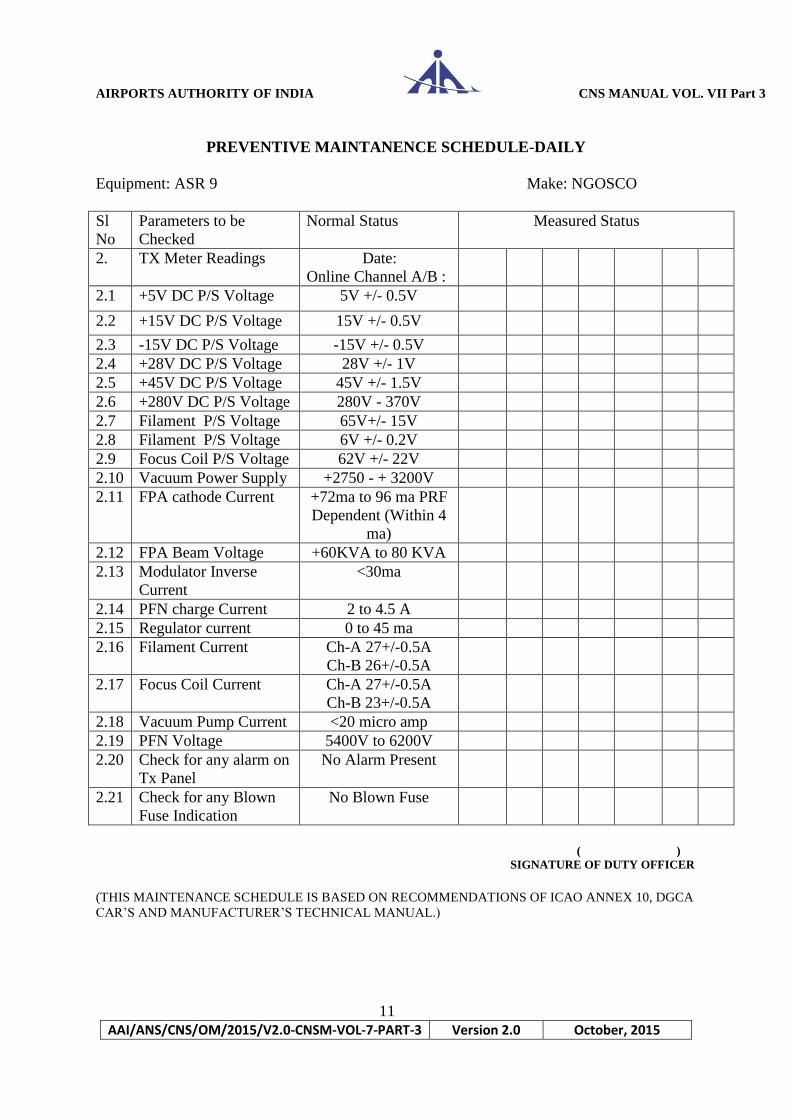
PREVENTIVE MAINTANENCE SCHEDULE-DAILY
Equipment: ASR 9 Make: NGOSCO
Sl
No
Parameters to be
Checked
Normal Status Measured Status
2. TX Meter Readings Date:
Online Channel A/B :
2.1 +5V DC P/S Voltage 5V +/- 0.5V
2.2 +15V DC P/S Voltage 15V +/- 0.5V
2.3 -15V DC P/S Voltage -15V +/- 0.5V
2.4 +28V DC P/S Voltage 28V +/- 1V
2.5 +45V DC P/S Voltage 45V +/- 1.5V
2.6 +280V DC P/S Voltage 280V - 370V
2.7 Filament P/S Voltage 65V+/- 15V
2.8 Filament P/S Voltage 6V +/- 0.2V
2.9 Focus Coil P/S Voltage 62V +/- 22V
2.10 Vacuum Power Supply +2750 - + 3200V
2.11 FPA cathode Current +72ma to 96 ma PRF
Dependent (Within 4
ma)
2.12 FPA Beam Voltage +60KVA to 80 KVA
2.13 Modulator Inverse
Current
<30ma
2.14 PFN charge Current 2 to 4.5 A
2.15 Regulator current 0 to 45 ma
2.16 Filament Current Ch-A 27+/-0.5A
Ch-B 26+/-0.5A
2.17 Focus Coil Current Ch-A 27+/-0.5A
Ch-B 23+/-0.5A
2.18 Vacuum Pump Current <20 micro amp
2.19 PFN Voltage 5400V to 6200V
2.20 Check for any alarm on
Tx Panel
No Alarm Present
2.21 Check for any Blown
Fuse Indication
No Blown Fuse
( )
SIGNATURE OF DUTY OFFICER
(THIS MAINTENANCE SCHEDULE IS BASED ON RECOMMENDATIONS OF ICAO ANNEX 10, DGCA
CAR’S AND MANUFACTURER’S TECHNICAL MANUAL.)

AIRPORTS AUTHORITY OF INDIA CNS MANUAL VOL. VII Part 3
12
AAI/ANS/CNS/OM/2015/V2.0-CNSM-VOL-7-PART-3 Version 2.0 October, 2015
PREVENTIVE MAINTANENCE SCHEDULE-DAILY
Equipment: ASR 9 Make: NGOSCO
Sl No Parameters to be
Checked
Normal Status Measured Status
Receiver - A
3.A.1 Stalo Level 0
3.A.2 +15 V P/S (D) +15V +/- 0.5V
3.A.3 -15 V P/S (A) -15V +/- 0.5V
3.A.4 +100 V P/S (A) +100V +/- 0.5V
3.A.5 +5 V P/S (C 3-4) +5V +/- 0.2V
3.A.6 +5 V P/S (C 1- 2) +5V +/- 0.2V
3.A.7 +15 V P/S (B) +15V+/- 1V
3.A.8 -15 V P/S (B) -15V+/- 1V
3.A.9 Status of Battery ON
3.A.10 Battery Voltage +265 +/- 35V
3.A.11 Check for Blown
Fuse
No Blown Fuse
3.A.12 Status of Fans O.K.
Receiver – B
3.B.1 Stalo Level 0
3.B.2 +15 V P/S (D) +15V +/- 0.5V
3.B.3 -15 V P/S (A) -15V +/- 0.5V
3.B.4 +100 V P/S (A) +100V +/- 0.5V
3.B.5 +5 V P/S (C 3-4) +5V +/- 0.2V
3.B.6 +5 V P/S (C 1- 2) +5V +/- 0.2V
3.B.7 +15 V P/S (B) +15V+/- 1V
3.B.8 -15 V P/S (B) -15V+/- 1V
3.B.9 Status of Battery ON
3.B.10 Battery Voltage +265 +/- 35V
3.B.11 Check for Blown
Fuse
No Blown Fuse
3.B.12 Status of Fans O.K.
( )
SIGNATURE OF DUTY OFFICER
(THIS MAINTENANCE SCHEDULE IS BASED ON RECOMMENDATIONS OF ICAO ANNEX 10, DGCA
CAR’S AND MANUFACTURER’S TECHNICAL MANUAL.)
AIRPORTS AUTHORITY OF INDIA CNS MANUAL VOL. VII Part 3
13
AAI/ANS/CNS/OM/2015/V2.0-CNSM-VOL-7-PART-3 Version 2.0 October, 2015
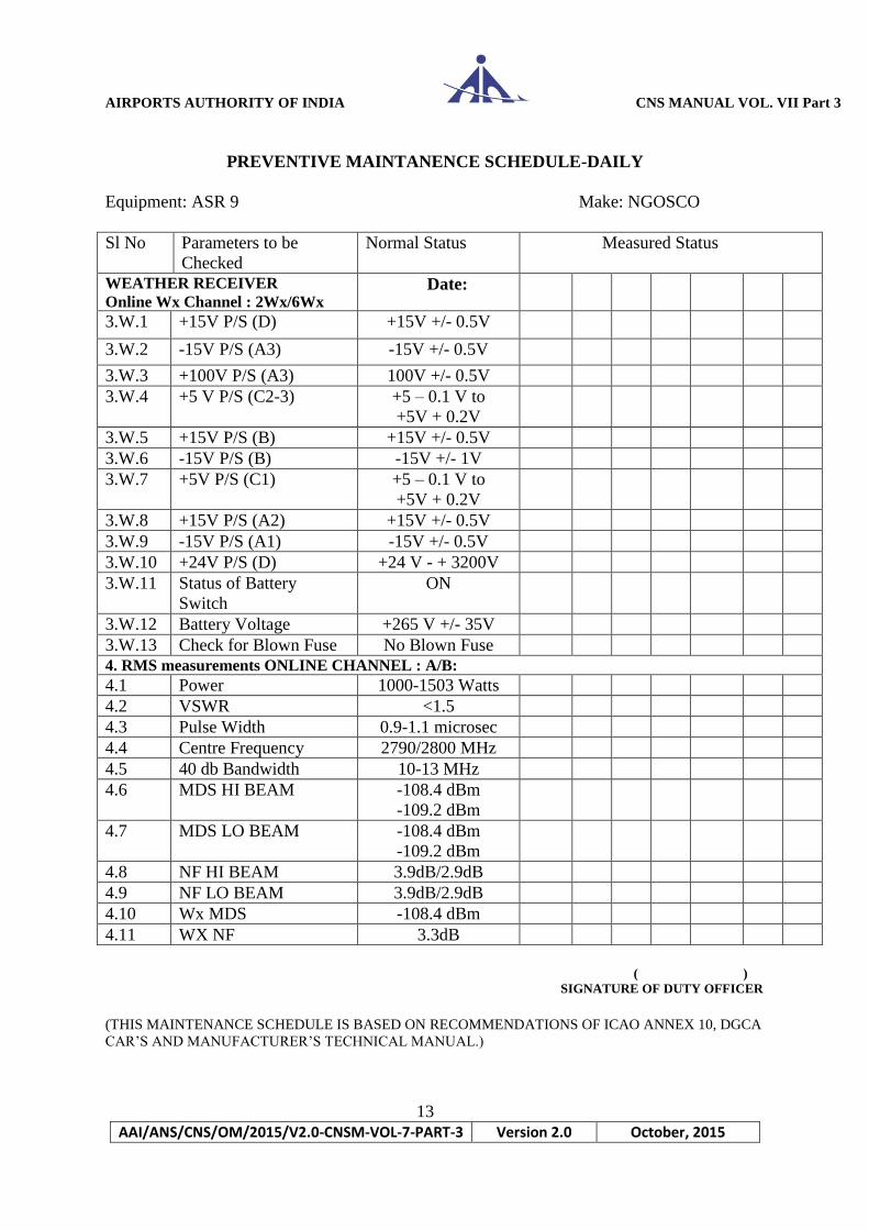
PREVENTIVE MAINTANENCE SCHEDULE-DAILY
Equipment: ASR 9 Make: NGOSCO
Sl No Parameters to be
Checked
Normal Status Measured Status
WEATHER RECEIVER
Online Wx Channel : 2Wx/6Wx Date:
3.W.1 +15V P/S (D) +15V +/- 0.5V
3.W.2 -15V P/S (A3) -15V +/- 0.5V
3.W.3 +100V P/S (A3) 100V +/- 0.5V
3.W.4 +5 V P/S (C2-3)
+5 – 0.1 V to
+5V + 0.2V
3.W.5 +15V P/S (B) +15V +/- 0.5V
3.W.6 -15V P/S (B) -15V +/- 1V
3.W.7 +5V P/S (C1) +5 – 0.1 V to
+5V + 0.2V
3.W.8 +15V P/S (A2) +15V +/- 0.5V
3.W.9 -15V P/S (A1) -15V +/- 0.5V
3.W.10 +24V P/S (D) +24 V - + 3200V
3.W.11 Status of Battery
Switch
ON
3.W.12 Battery Voltage +265 V +/- 35V
3.W.13 Check for Blown Fuse No Blown Fuse
4. RMS measurements ONLINE CHANNEL : A/B:
4.1 Power 1000-1503 Watts
4.2 VSWR <1.5
4.3 Pulse Width 0.9-1.1 microsec
4.4 Centre Frequency 2790/2800 MHz
4.5 40 db Bandwidth 10-13 MHz
4.6 MDS HI BEAM -108.4 dBm
-109.2 dBm
4.7 MDS LO BEAM -108.4 dBm
-109.2 dBm
4.8 NF HI BEAM 3.9dB/2.9dB
4.9 NF LO BEAM 3.9dB/2.9dB
4.10 Wx MDS -108.4 dBm
4.11 WX NF 3.3dB
( )
SIGNATURE OF DUTY OFFICER
(THIS MAINTENANCE SCHEDULE IS BASED ON RECOMMENDATIONS OF ICAO ANNEX 10, DGCA
CAR’S AND MANUFACTURER’S TECHNICAL MANUAL.)

AIRPORTS AUTHORITY OF INDIA CNS MANUAL VOL. VII Part 3
14
AAI/ANS/CNS/OM/2015/V2.0-CNSM-VOL-7-PART-3 Version 2.0 October, 2015
PREVENTIVE MAINTANENCE SCHEDULE-DAILY
Equipment: ASR 9 Make: NGOSCO
Sl
No
Parameters to be
Checked
Normal Status Measured Status
4. RMS MEASUREMENT Date:
4.12 Filament Current Nameplate +/-3.0A
4.13 Filament Coil Current Nameplate +/-3.0A
4.14 Klystron Voltage 60.2 KV to 80.5 KV
4.15 Klystron Current 71.9 ma to 96.1 ma (PRF
Dependent) +/- 4.0 ma)
4.16 PFN Voltage +5400 V to 5700 V
4.17 Vacuum Pump Current <20 micro amp
STANDBY CHANNEL
4.18 Power 1000-1503 Watts
4.19 Pulse Width 0.9-1.1 micro sec
4.20 Centre Frequency 2790/2800 MHz
4.21 40 dB Bandwidth 10-13 MHz
4.22 MDS HI BEAM -108.4 dBm
-109.6 dBm
4.23 MDS LO BEAM -108.0 dBm
-109.2 dBm
4.24 NF HI BEAM 3.9dB/2.9dB
4.25 NF Lo BEAM 3.9dB/2.9dB
ANTENNA PEDESTAL CONTROL UNIT
5.1 Motor 1 ----24 V 24V +/- 1.2 V
5.2 Motor 1 ----5 V 5V +/- 0.05 V
5.3 Motor 2 ----24 V 24V +/- 1.2 V
5.4 Motor 2 ----5 V 5V +/- 0.05 V
5.5 Check Lamp Indication for
incoming supply
O.K.
5.6 Check Lamp Indication for
Motor 1 supply
O.K.
5.7 Check Lamp Indication for
Motor 2 supply
O.K.
5.8 Check Lamp Indication for
Interlocks
O.K.
5.9 Check whether both the shaft of
motor are rotation with antenna O.K.
5.10 Status of Antenna Switch
Lamp
O.K.
( )
SIGNATURE OF DUTY OFFICER
(THIS MAINTENANCE SCHEDULE IS BASED ON RECOMMENDATIONS OF ICAO ANNEX 10, DGCA
CAR’S AND MANUFACTURER’S TECHNICAL MANUAL.)

AIRPORTS AUTHORITY OF INDIA CNS MANUAL VOL. VII Part 3
15
AAI/ANS/CNS/OM/2015/V2.0-CNSM-VOL-7-PART-3 Version 2.0 October, 2015
PREVENTIVE MAINTANENCE SCHEDULE-DAILY
Equipment: ASR 9 Make: NGOSCO
Sl
No
Parameters to be Checked Normal Status Measured Status
6. Miscellaneous
6.1 RMS + 15 V Supply 15.0V +/- 1 V
6.2 RMS + 5 V Supply 5.0 V +/-0.3 V
6.3 Status of Building Alarm
Lamp ‘A’
O.K.
6.4 Status of Building Alarm
Lamp ‘A’
O.K.
6.5 Waveguide
Pressurizer No. 1
A) Output Pressure 10 psi
B) Tank Pressure 35 psi
6.6 Waveguide
Pressurizer No. 1
A) Output Pressure 10 psi
B) Tank Pressure 35 psi
7. Deviation from Normal Status/ Readings Noticed
S.
No
Date Details of Deviation Action Taken Remarks if any Signature of
Duty Officer
( )
SIGNATURE OF DUTY OFFICER
NAME:
DESIG:
COMMENTS/ACTION TAKEN DETAILS:
( )
SIGNATURE OF UNIT INCHARGE.
NAME:
DESIG:
(THIS MAINTENANCE SCHEDULE IS BASED ON RECOMMENDATIONS OF ICAO ANNEX 10, DGCA
CAR’S AND MANUFACTURER’S TECHNICAL MANUAL.)

AIRPORTS AUTHORITY OF INDIA CNS MANUAL VOL. VII Part 3
16
AAI/ANS/CNS/OM/2015/V2.0-CNSM-VOL-7-PART-3 Version 2.0 October, 2015
PREVENTIVE MAINTANENCE SCHEDULE-Monthly
Equipment: ASR 9 Make: NGOSCO Channel:
S
No
TASKS TO BE PERFORMED STATUS REMARKS
1. Calibration of RMS
MDS Measurement : LO Beam- 108.0dBm/-109.6 dBm
HI Beam- 108.4dBm/-109.2 dBm
PERFORMED
2. Check Power Supply Output Voltages
A. TRANSMITTERS
(1) +5 V P/S
(2) +15 V P/S
(3) -15 V P/S
(4) +28 V P/S
(5) +45 V P/S
(6) +280 V P/S
(7) Filament P/S Voltage 65 +/- 15 V
(8)Filament Coil P/S Voltage 62 +/- 15 V
B. RECEIVER
(1) +15 V P/S
(2) -15 V P/S
(3) +100 V P/S (A)
(4) +5 V P/S (C3-4)
(5) +5 V P/S (C1-2)
(6) +15 V P/S (B)
(7) -15 V P/S (B)
( )
SIGNATURE OF DUTY OFFICER.
(THIS MAINTENANCE SCHEDULE IS BASED ON RECOMMENDATIONS OF ICAO ANNEX 10, DGCA
CAR’S AND MANUFACTURER’S TECHNICAL MANUAL.)

AIRPORTS AUTHORITY OF INDIA CNS MANUAL VOL. VII Part 3
17
AAI/ANS/CNS/OM/2015/V2.0-CNSM-VOL-7-PART-3 Version 2.0 October, 2015
PREVENTIVE MAINTANENCE SCHEDULE-MONTHLY
Equipment: ASR 9 Make: NGOSCO Channel: WEATHER
S
No
TASKS TO BE PERFORMED STATUS REMARKS
1. Check Power Supply Output Voltages
(1) +15 V P/S (D) +15V +/- 0.5V
(2) -15 V P/S (A3) -15V +/- 0.5V
(3) +100 V P/S (A3) +100V +/- 0.5V
(4) +5 V P/S (C2-3) (5V-0.1V) - (5V-0.2V)
(5) +15 V P/S (B) +15V +/- 1V
(6) -15 V P/S (B) -15V +/- 1V
(7) +5 V P/S (C1) (5V-0.1V) - (5V-0.2V)
(8) +15 V P/S (A2) +15V +/- 0.5V
(9) -15 V P/S (A1) -15V +/- 0.5V
(10)+24 V P/S(D) +24V +/- 0.5V
2. Check the Status of Fans
3. Check the Power Supply Battery Voltage
4. PERFORM SYSTEM STABILITY CHECK
5. CHECK TARGET CHANNEL RECEIVER
RECOVERY
( )
SIGNATURE OF DUTY OFFICER
NAME:
DESIG:
COMMENTS/ACTION TAKEN DETAILS:
( )
SIGNATURE OF UNIT INCHARGE.
NAME:
DESIG:
(THIS MAINTENANCE SCHEDULE IS BASED ON RECOMMENDATIONS OF ICAO ANNEX 10, DGCA
CAR’S AND MANUFACTURER’S TECHNICAL MANUAL.)
AIRPORTS AUTHORITY OF INDIA CNS MANUAL VOL. VII Part 3
18
AAI/ANS/CNS/OM/2015/V2.0-CNSM-VOL-7-PART-3 Version 2.0 October, 2015
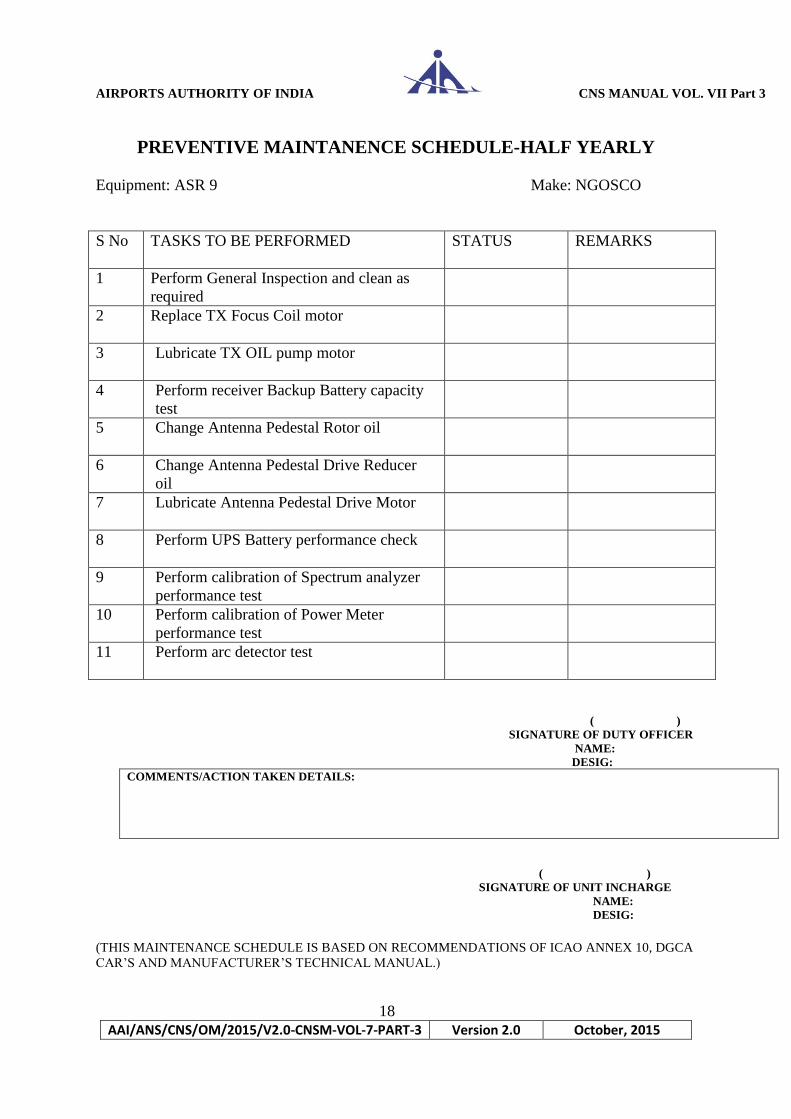
PREVENTIVE MAINTANENCE SCHEDULE-HALF YEARLY
Equipment: ASR 9 Make: NGOSCO
S No TASKS TO BE PERFORMED STATUS REMARKS
1 Perform General Inspection and clean as
required
2 Replace TX Focus Coil motor
3 Lubricate TX OIL pump motor
4 Perform receiver Backup Battery capacity
test
5 Change Antenna Pedestal Rotor oil
6 Change Antenna Pedestal Drive Reducer
oil
7 Lubricate Antenna Pedestal Drive Motor
8 Perform UPS Battery performance check
9 Perform calibration of Spectrum analyzer
performance test
10 Perform calibration of Power Meter
performance test
11 Perform arc detector test
( )
SIGNATURE OF DUTY OFFICER
NAME:
DESIG:
COMMENTS/ACTION TAKEN DETAILS:
( )
SIGNATURE OF UNIT INCHARGE
NAME:
DESIG:
(THIS MAINTENANCE SCHEDULE IS BASED ON RECOMMENDATIONS OF ICAO ANNEX 10, DGCA
CAR’S AND MANUFACTURER’S TECHNICAL MANUAL.)

AIRPORTS AUTHORITY OF INDIA CNS MANUAL VOL. VII Part 3
19
AAI/ANS/CNS/OM/2015/V2.0-CNSM-VOL-7-PART-3 Version 2.0 October, 2015
PREVENTIVE MAINTENANCE SCHEDULE OF MSSR SITE-DAILY
MAKE: NGOSCO Station: Date:
Parameters to be checked Normal Status
1.0 General
1.1 On Line Channel 1 or 2
1.2 Status of Online
Channel Green/Yellow
/Red
Status of Local Terminal O.K.
Status of Remote Terminal O.K.
Status of PC Rappi O.K.
Status of CPMEs O.K.
Change of Channel 1 to 2 or
vice versa
Room Temperature 18-22
1.10 Shelter Cleanliness Dust Free
Equipment Cleanliness Dust Free
2. INTERROGATOR PANEL
2.1 Check the lamp indication for Glowing
input three phase supply
2.2 Check the Status of Breaker ON
Alarm Switch
2.3 Check all lamps using lamp
test OK

AIRPORTS AUTHORITY OF INDIA CNS MANUAL VOL. VII Part 3
20
AAI/ANS/CNS/OM/2015/V2.0-CNSM-VOL-7-PART-3 Version 2.0 October, 2015
2.4
Check if any fault Monitor Lamp No Lamp
is glowing should glow
3.
3.1 SLS ATCRBS Tx Power
3.2 Main Normal Mode S Tx Power
3.3 SLS Normal Mode S Tx Power
3.4 Main High Mode S Tx Power
3.5 SLS High Mode S Tx Power
3.6 Mian ATCRBS Tx Power
3.7 Sum Channel Gain
3.8 Delta Channel Gain
3.9 Omni Channel Gain
3.10 Sum Channel Noise
3.11 Delta Channel Noise
3.12 Omni Channel Noise
3.13 VSWR Main Transmitter
3.14 VSWR Aux. Transmitter
3.15 Cabinet Temperature-1
3.16 Cabinet Temperature-2
3.17 Cabinet Temperature-3
3.18 Cabinet Temperature-4
3.19 Cabinet Temperature-5
3.20 Cabinet Temperature-6
3.21 Cabinet Temperature-7
3.22 Cabinet Temperature-8
4.1 SLS ATCRBS Tx Power
4.2 Main Normal Mode S Tx
Power
4.3 SLS Normal Mode S Tx Power
4.4 Main High Mode S Tx Power

AIRPORTS AUTHORITY OF INDIA CNS MANUAL VOL. VII Part 3
21
AAI/ANS/CNS/OM/2015/V2.0-CNSM-VOL-7-PART-3 Version 2.0 October, 2015
4.5 SLS High Mode S Tx Power
4.6 Mian ATCRBS Tx Power
4.7 Sum Channel Gain
4.8 Delta Channel Gain
4.9 Omni Channel Gain
4.10 Sum Channel Noise
4.11 Delta Channel Noise
4.12 Omni Channel Noise
4.13 VSWR Main Transmitter
4.14 VSWR Aux. Transmitter
4.15 Cabinet Temperature-1
4.16 Cabinet Temperature-2
4.17 Cabinet Temperature-3
4.18 Cabinet Temperature-4
4.19 Cabinet Temperature-5
4.20 Cabinet Temperature-6
4.21 Cabinet Temperature-7
4.22 Cabinet Temperature-8
5. BUILT IN TEST STATUS
5.1 Interrogator 1 Built in Test Green/Yellow
/Red
5.2 Interrogator 2 Built in Test Green/Yellow
/Red
5.3 DPS Channel 1 Built in Test Green/Yellow
/Red
5.4 DPS Channel 2 Built in Test Green/Yellow
/Red
5.5 DPS I/O Built in Test Green/Yellow
/Red
AIRPORTS AUTHORITY OF INDIA CNS MANUAL VOL. VII Part 3
22
AAI/ANS/CNS/OM/2015/V2.0-CNSM-VOL-7-PART-3 Version 2.0 October, 2015
( )
SIGNATURE OF DUTY OFFICER
NAME:
DESIG:
COMMENTS/ACTION TAKEN DETAILS:
( )
SIGNATURE OF UNIT INCHARGE
NAME:
DESIG:
(THIS MAINTENANCE SCHEDULE IS BASED ON RECOMMENDATIONS OF ICAO ANNEX 10, DGCA
CAR’S AND MANUFACTURER’S TECHNICAL MANUAL.)
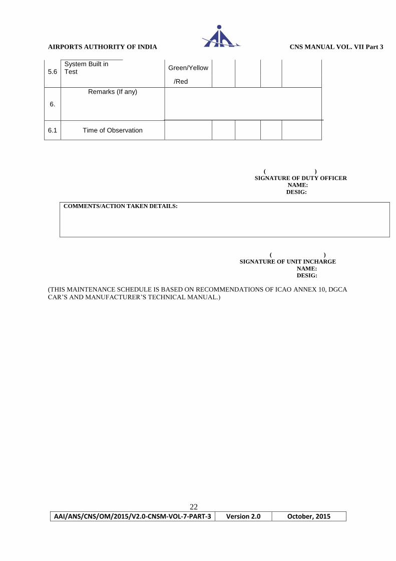
5.6 System Built in Test
Green/Yellow
/Red
6.
Remarks (If any)
6.1 Time of Observation
AIRPORTS AUTHORITY OF INDIA CNS MANUAL VOL. VII Part 3
23
AAI/ANS/CNS/OM/2015/V2.0-CNSM-VOL-7-PART-3 Version 2.0 October, 2015
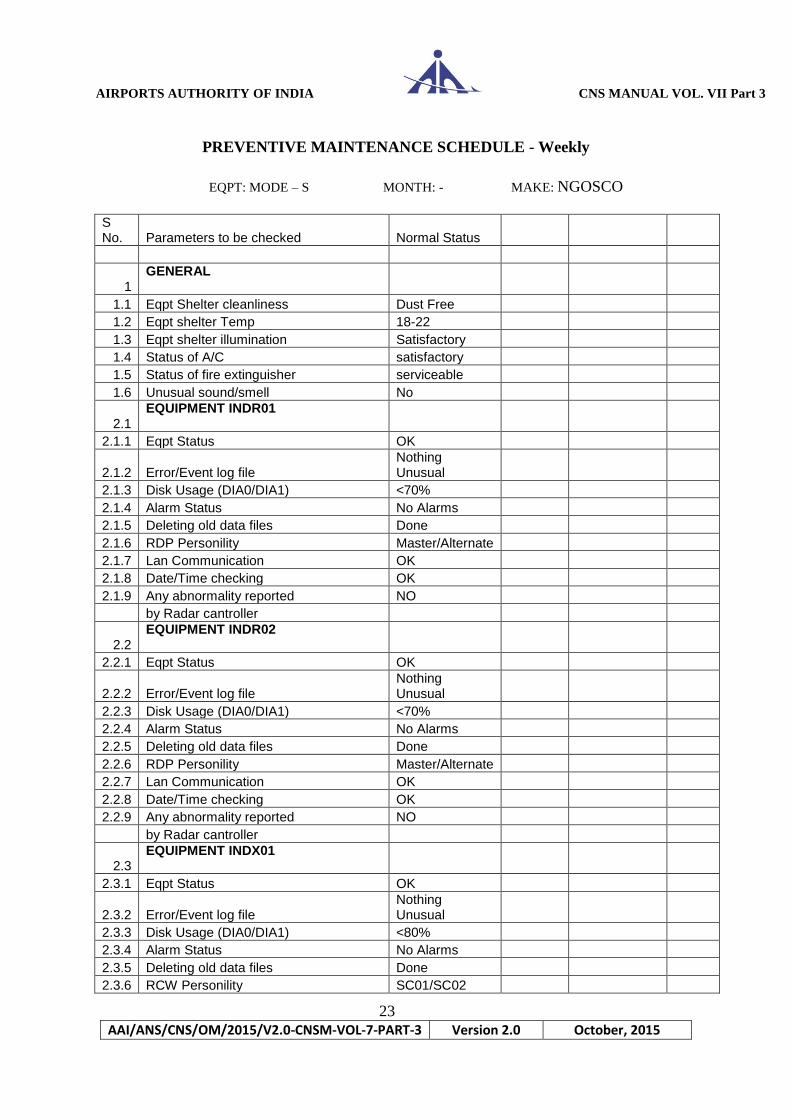
PREVENTIVE MAINTENANCE SCHEDULE - Weekly
EQPT: MODE – S MONTH: - MAKE: NGOSCO
S No. Parameters to be checked Normal Status
1 GENERAL
1.1 Eqpt Shelter cleanliness Dust Free
1.2 Eqpt shelter Temp 18-22
1.3 Eqpt shelter illumination Satisfactory
1.4 Status of A/C satisfactory
1.5 Status of fire extinguisher serviceable
1.6 Unusual sound/smell No
2.1 EQUIPMENT INDR01
2.1.1 Eqpt Status OK
2.1.2 Error/Event log file Nothing Unusual
2.1.3 Disk Usage (DIA0/DIA1) <70%
2.1.4 Alarm Status No Alarms
2.1.5 Deleting old data files Done
2.1.6 RDP Personility Master/Alternate
2.1.7 Lan Communication OK
2.1.8 Date/Time checking OK
2.1.9 Any abnormality reported NO
by Radar cantroller
2.2 EQUIPMENT INDR02
2.2.1 Eqpt Status OK
2.2.2 Error/Event log file Nothing Unusual
2.2.3 Disk Usage (DIA0/DIA1) <70%
2.2.4 Alarm Status No Alarms
2.2.5 Deleting old data files Done
2.2.6 RDP Personility Master/Alternate
2.2.7 Lan Communication OK
2.2.8 Date/Time checking OK
2.2.9 Any abnormality reported NO
by Radar cantroller
2.3 EQUIPMENT INDX01
2.3.1 Eqpt Status OK
2.3.2 Error/Event log file Nothing Unusual
2.3.3 Disk Usage (DIA0/DIA1) <80%
2.3.4 Alarm Status No Alarms
2.3.5 Deleting old data files Done
2.3.6 RCW Personility SC01/SC02
AIRPORTS AUTHORITY OF INDIA CNS MANUAL VOL. VII Part 3
24
AAI/ANS/CNS/OM/2015/V2.0-CNSM-VOL-7-PART-3 Version 2.0 October, 2015
2.3.7 Lan Communication OK
2.3.8 Date/Time checking OK
2.3.9 Any abnormality reported NO
by Radar cantroller
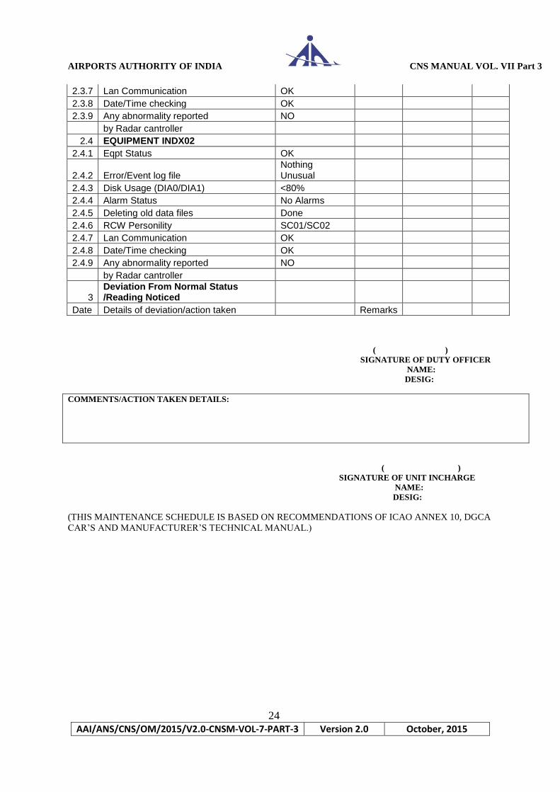
2.4 EQUIPMENT INDX02
2.4.1 Eqpt Status OK
2.4.2 Error/Event log file Nothing Unusual
2.4.3 Disk Usage (DIA0/DIA1) <80%
2.4.4 Alarm Status No Alarms
2.4.5 Deleting old data files Done
2.4.6 RCW Personility SC01/SC02
2.4.7 Lan Communication OK
2.4.8 Date/Time checking OK
2.4.9 Any abnormality reported NO
by Radar cantroller
3 Deviation From Normal Status /Reading Noticed
Date Details of deviation/action taken Remarks
( )
SIGNATURE OF DUTY OFFICER
NAME:
DESIG:
COMMENTS/ACTION TAKEN DETAILS:
( )
SIGNATURE OF UNIT INCHARGE
NAME:
DESIG:
(THIS MAINTENANCE SCHEDULE IS BASED ON RECOMMENDATIONS OF ICAO ANNEX 10, DGCA
CAR’S AND MANUFACTURER’S TECHNICAL MANUAL.)

AIRPORTS AUTHORITY OF INDIA CNS MANUAL VOL. VII Part 3
25
AAI/ANS/CNS/OM/2015/V2.0-CNSM-VOL-7-PART-3 Version 2.0 October, 2015
PREVENTIVE MAINTENANCE SCHEDULE - MONTHLY
EQPT: MODE – S MONTH: - MAKE: NGOSCO
SL.
NO.
TASK TO BE PERFORMED MEASURED STATUS REMARKS
1 POWER SUPPLY DC OUTPUT VOLTAGE INT - 1 INT – 2
1.A. INTERROGATOR
PS1 (+15V + 0.1V)
PS2 (-15V + 0.1V)
PS3 (+5V + 0.1V)
PS4 (+36V + O.7V)
PS5 (+52V + 2.0V)
1.B. DPS
V1 (+5V + 0.1V)
V2 (+15V + 0.1V)
V3 (-15V +0.1V)
1.C. PCU VOLTAGE
i) TP1 (0V)
ii) TP2 (0V)
iii) TP3 (0V)
iv) TP4 (0V)
v) TP5 (+24V)
vi) TP6 (+24V)
vii) TP7 (1.4V)
2. PERFORM LAMP TEST
i) INTERROGATOR
ii) PCU
3 PERFORM CIRCUIT BREAKER TEST
ALARM
4. PERFORM GENERAL INSPECTION AND
CLEANINGN OF CABINET
i) INTERROGATOR
ii) DPS
iii) PCU
5. CLEAN AND REPLACE AIR FILTERS
i) INTERROGATOR
ii) DPS
( )
SIGNATURE OF DUTY OFFICER
NAME:
DESIG: COMMENTS/ACTION TAKEN DETAILS:
( )
SIGNATURE OF UNIT INCHARGE
NAME:
DESIG: (THIS MAINTENANCE SCHEDULE IS BASED ON RECOMMENDATIONS OF ICAO ANNEX 10, DGCA
CAR’S AND MANUFACTURER’S TECHNICAL MANUAL.)
AIRPORTS AUTHORITY OF INDIA CNS MANUAL VOL. VII Part 3
26
AAI/ANS/CNS/OM/2015/V2.0-CNSM-VOL-7-PART-3 Version 2.0 October, 2015
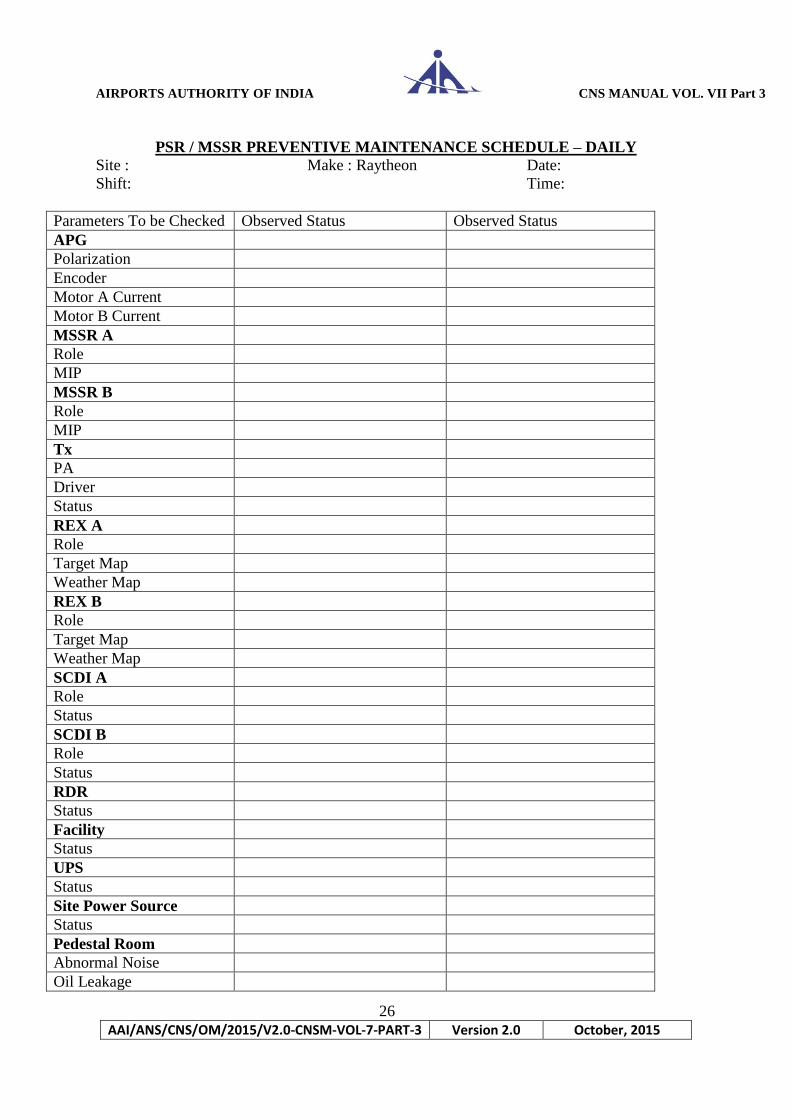
PSR / MSSR PREVENTIVE MAINTENANCE SCHEDULE – DAILY
Site : Make : Raytheon Date:
Shift: Time:
Parameters To be Checked Observed Status Observed Status
APG
Polarization
Encoder
Motor A Current
Motor B Current
MSSR A
Role
MIP
MSSR B
Role
MIP
Tx
PA
Driver
Status
REX A
Role
Target Map
Weather Map
REX B
Role
Target Map
Weather Map
SCDI A
Role
Status
SCDI B
Role
Status
RDR
Status
Facility
Status
UPS
Status
Site Power Source
Status
Pedestal Room
Abnormal Noise
Oil Leakage

AIRPORTS AUTHORITY OF INDIA CNS MANUAL VOL. VII Part 3
27
AAI/ANS/CNS/OM/2015/V2.0-CNSM-VOL-7-PART-3 Version 2.0 October, 2015
End to End
Test Rex/ SDP - A Rex/SDP - B Rex/ SDP - A Rex/ SDP - B
Noise Level Noise Level Noise Level Noise Level
Target (High)
Target (Low)
Weather
Phase Stability
Test
Rex / SDP-A Rex/SDP-B Rex / SDP-A Rex/SDP-B
Target Lo Beam
SP
Target Lo Beam
LP
Target Hi Beam
SP
Target Hi Beam
LP
Weather SP
Weather SP
Probability of
Detection
Pd,
Minute
Pd,
Hour
dRange dAzimuth Pd,
Minute
Pd,
Hour
dRange dAzimuth
MSSR Parrot
PSR PE1
PSR PE2
PSR PE3
Radar Data
Count MSSR PSR MSSR PSR
Last Scan Per Minute Last Scan Per Minute Last Scan Per
Minute Last Scan Per Minute
Coast
Multiple Comb
Primitive
Solo
Test Targets
Parrot / PE Solo in PSR Range /
Wx
Combined
Targets Last Scan Per Minute Last Scan Per Minute
Radar Statistics MSSR1/
MSSR2 PSR1/PSR2 MSSR/PSR
MSSR1/
MSSR2 PSR1/PSR2 MSSR/PSR
Range,nmi
Azimuth,degree
(Signature of Duty Officer) (Signature of Unit In-Charge)
(THIS MAINTENANCE SCHEDULE IS BASED ON RECOMMENDATIONS OF ICAO ANNEX 10, DGCA
CAR’S AND MANUFACTURER’S TECHNICAL MANUAL.)
AIRPORTS AUTHORITY OF INDIA CNS MANUAL VOL. VII Part 3
28
AAI/ANS/CNS/OM/2015/V2.0-CNSM-VOL-7-PART-3 Version 2.0 October, 2015
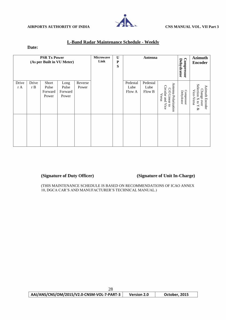
L-Band Radar Maintenance Schedule - Weekly
Date:
PSR Tx Power
(As per Built in VU Meter)
Microwave
Link U
P
S
Antenna Co
mp
resso
r
Deh
yd
rato
r
Azimuth
Encoder
Drive
r A
Drive
r B
Short
Pulse
Forward
Power
Long
Pulse
Forward
Power
Reverse
Power
Pedestal
Lube
Flow A
Pedestal
Lube
Flow B
An
tenn
a Po
larization
C/O
Lin
ear to
Circu
lar and
Vice
Versa
Co
mp
ressor
Deh
yd
rator
Azim
uth
En
cod
er
Ch
ang
e ov
er
Selectio
n X
to Y
&
Vice-V
ersa
(Signature of Duty Officer) (Signature of Unit In-Charge)
(THIS MAINTENANCE SCHEDULE IS BASED ON RECOMMENDATIONS OF ICAO ANNEX
10, DGCA CAR’S AND MANUFACTURER’S TECHNICAL MANUAL.)

AIRPORTS AUTHORITY OF INDIA CNS MANUAL VOL. VII Part 3
29
AAI/ANS/CNS/OM/2015/V2.0-CNSM-VOL-7-PART-3 Version 2.0 October, 2015
MSSR Weekly Check
(Ref System Manual Sec 3, Annex A, P29 to P36)
Station : L-Band Radar, IGI Airport Palam, New Delhi Date:
1. Test points representing over 200 BIT functions for the selected MSSR channel (A
channel first week and third week B Channel second and fourth week) may be printed
out values may be evaluated.
2. System
Statistical data for Channel A and Channel B
Voltages and dB values for Channel A and Channel B
Channel A Channel B
Tx Sum Power dBW
Control Power dBW
-70 V
-5.2 V
+15 V
+65 V
-15 V
+5 V
+28 V
+50 V
RDC +5.0 V
SP +5.0 V
AIRPORTS AUTHORITY OF INDIA CNS MANUAL VOL. VII Part 3
30
AAI/ANS/CNS/OM/2015/V2.0-CNSM-VOL-7-PART-3 Version 2.0 October, 2015
3. Antenna Pattern Measurement may be carried out first week and third week for
channel A and second and fourth week for channel B. Observations may be
evaluated.
(Signature of Duty Officer) (Signature of Unit In-Charge)
(THIS MAINTENANCE SCHEDULE IS BASED ON RECOMMENDATIONS OF ICAO ANNEX
10, DGCA CAR’S AND MANUFACTURER’S TECHNICAL MANUAL.)
AIRPORTS AUTHORITY OF INDIA CNS MANUAL VOL. VII Part 3
31
AAI/ANS/CNS/OM/2015/V2.0-CNSM-VOL-7-PART-3 Version 2.0 October, 2015
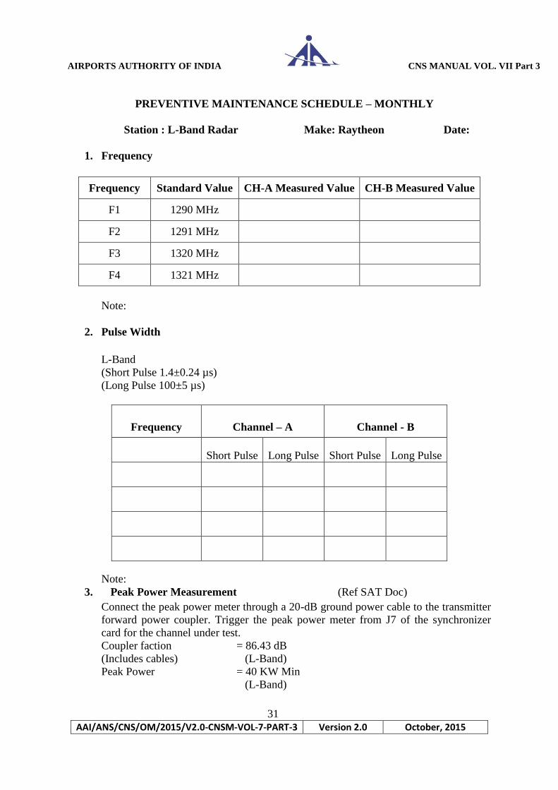
PREVENTIVE MAINTENANCE SCHEDULE – MONTHLY
Station : L-Band Radar Make: Raytheon Date:
1. Frequency
Frequency Standard Value CH-A Measured Value CH-B Measured Value
F1 1290 MHz
F2 1291 MHz
F3 1320 MHz
F4 1321 MHz
Note:
2. Pulse Width
L-Band
(Short Pulse 1.4±0.24 µs)
(Long Pulse 100±5 µs)
Frequency Channel – A Channel - B
Short Pulse Long Pulse Short Pulse Long Pulse
Note:
3. Peak Power Measurement (Ref SAT Doc)
Connect the peak power meter through a 20-dB ground power cable to the transmitter
forward power coupler. Trigger the peak power meter from J7 of the synchronizer
card for the channel under test.
Coupler faction = 86.43 dB
(Includes cables) (L-Band)
Peak Power = 40 KW Min
(L-Band)

AIRPORTS AUTHORITY OF INDIA CNS MANUAL VOL. VII Part 3
32
AAI/ANS/CNS/OM/2015/V2.0-CNSM-VOL-7-PART-3 Version 2.0 October, 2015
Tx Module
Channel A Channel B
Measured Short
Pulse Power
Measured Long
Pulse Power
Measured Short
Pulse Power
Measured Long
Pulse Power
TX#1
TX#2
TX#3
TX#4
TX#5
TX#6
TX#7
TX#8
TX#9
TX#10
TX#11
TX#12
TX#13
TX#14
TX#15
TX#16
Note:
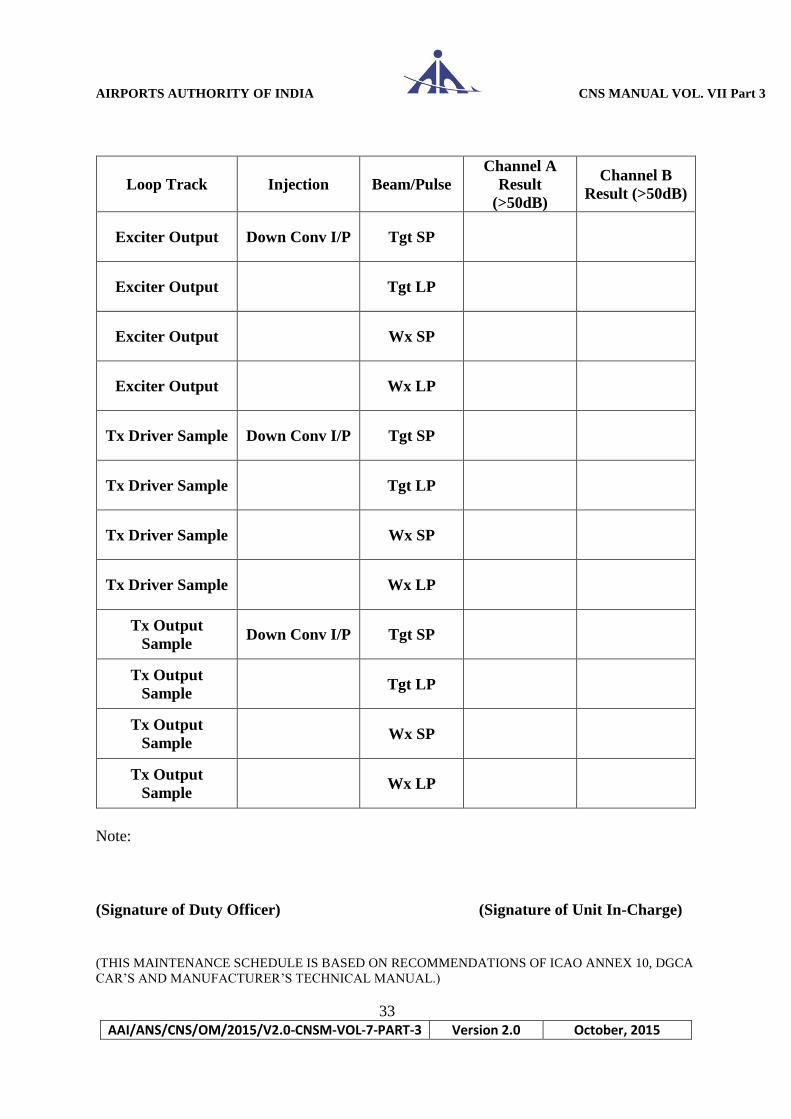
4. As per Stability Measurement (Ref SAT Doc)
At the on line selected SCDI select the PSR (Channel A or B) Manual Stability Test
Control/Result Menu.
AIRPORTS AUTHORITY OF INDIA CNS MANUAL VOL. VII Part 3
33
AAI/ANS/CNS/OM/2015/V2.0-CNSM-VOL-7-PART-3 Version 2.0 October, 2015
Loop Track Injection Beam/Pulse
Channel A
Result
(>50dB)
Channel B
Result (>50dB)
Exciter Output Down Conv I/P Tgt SP
Exciter Output Tgt LP
Exciter Output Wx SP
Exciter Output Wx LP
Tx Driver Sample Down Conv I/P Tgt SP
Tx Driver Sample Tgt LP
Tx Driver Sample Wx SP
Tx Driver Sample Wx LP
Tx Output
Sample Down Conv I/P Tgt SP
Tx Output
Sample Tgt LP
Tx Output
Sample Wx SP
Tx Output
Sample Wx LP
Note:
(Signature of Duty Officer) (Signature of Unit In-Charge)
(THIS MAINTENANCE SCHEDULE IS BASED ON RECOMMENDATIONS OF ICAO ANNEX 10, DGCA
CAR’S AND MANUFACTURER’S TECHNICAL MANUAL.)

AIRPORTS AUTHORITY OF INDIA CNS MANUAL VOL. VII Part 3
34
AAI/ANS/CNS/OM/2015/V2.0-CNSM-VOL-7-PART-3 Version 2.0 October, 2015
Maintenance Schedule of Power Supplies (Raytheon23SS) (Ref PSR Sec5 of Equipment Manual)
Date:
S.
N.
Unit/
Assembly
Service
Required Remarks
1 REX
DC Power
Supplies
(Monthly)
Unit 8V(8±0.4) 18.5(18.5±0.9V
) -8V
-
18.5V
A11A2(B)
A11A2(B)
Spare Power
Supplies
(Quarterly)
G440627-1
2 SDP
DC Power
Supplies
(Monthly)
Unit 5V(+0.2/-
0.085) 12V ± 0.2v -12V ± 0.2V
A11A1(B)
A11A1(B)
Spare Power
Supplies
(Quarterly)
G440535-1
3 APC
UPS Battery Back Time
Note: Reset both SCDIs and SDPs one by one once in a month.
(Signature of the duty Officer) (Signature of Unit-In-Charge)
(THIS MAINTENANCE SCHEDULE IS BASED ON RECOMMENDATIONS OF ICAO ANNEX 10,
DGCA CAR’S AND MANUFACTURER’S TECHNICAL MANUAL.)

AIRPORTS AUTHORITY OF INDIA CNS MANUAL VOL. VII Part 3
35
AAI/ANS/CNS/OM/2015/V2.0-CNSM-VOL-7-PART-3 Version 2.0 October, 2015
MSSR MAINTENANCE SCHEDULE - MONTHLY
Station: L-Band Radar Date:
Pulse Width and Spacing Measurement
Sr
No Measurements Parameters Standard Value
Measured / Actual
Value
1 P1 Width 0.8 ± 0.1
2 P2 Width 0.8 ± 0.05 – 0.1
3 P1 Width 0.8 ± 0.1
4 P1 Width 0.8 ± 0.1
5 P1 Width 16.25 or 30.25 ± 0.6
6 P1 Width 2.0 ± 0.07
7 P2 Leading Edge to P6 Sync Phase
Reversal 2.75 ± 0.1
8 P6 Leading Edge to P6 Sync Phase
Reversal 1.25 ± 0.04
(Sign of Unit In-Charge) (Sign of Duty Officer)
(THIS MAINTENANCE SCHEDULE IS BASED ON RECOMMENDATIONS OF ICAO ANNEX 10,
DGCA CAR’S AND MANUFACTURER’S TECHNICAL MANUAL.)
AIRPORTS AUTHORITY OF INDIA CNS MANUAL VOL. VII Part 3
36
AAI/ANS/CNS/OM/2015/V2.0-CNSM-VOL-7-PART-3 Version 2.0 October, 2015
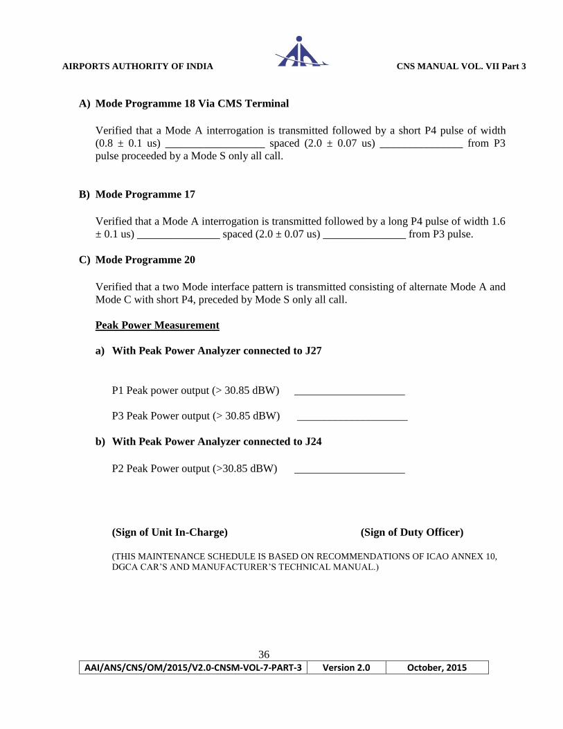
A) Mode Programme 18 Via CMS Terminal
Verified that a Mode A interrogation is transmitted followed by a short P4 pulse of width
(0.8 ± 0.1 us) __________________ spaced (2.0 ± 0.07 us) _______________ from P3
pulse proceeded by a Mode S only all call.
B) Mode Programme 17
Verified that a Mode A interrogation is transmitted followed by a long P4 pulse of width 1.6
± 0.1 us) _______________ spaced (2.0 ± 0.07 us) _______________ from P3 pulse.
C) Mode Programme 20
Verified that a two Mode interface pattern is transmitted consisting of alternate Mode A and
Mode C with short P4, preceded by Mode S only all call.
Peak Power Measurement
a) With Peak Power Analyzer connected to J27
P1 Peak power output (> 30.85 dBW) ____________________
P3 Peak Power output (> 30.85 dBW) ____________________
b) With Peak Power Analyzer connected to J24
P2 Peak Power output (>30.85 dBW) ____________________
(Sign of Unit In-Charge) (Sign of Duty Officer)
(THIS MAINTENANCE SCHEDULE IS BASED ON RECOMMENDATIONS OF ICAO ANNEX 10,
DGCA CAR’S AND MANUFACTURER’S TECHNICAL MANUAL.)

AIRPORTS AUTHORITY OF INDIA CNS MANUAL VOL. VII Part 3
37
AAI/ANS/CNS/OM/2015/V2.0-CNSM-VOL-7-PART-3 Version 2.0 October, 2015
Quarterly Maintenance Schedule of PSR (Raytheon ASR10SS/23SS)
Station: L-Band Radar Date:
SN Unit /Assembly +40 V +30V +5 -15V Remarks
1 Driver-A
2 Driver-B
3 PA-
4 PA-2
5 PA-3
6 PA-4
7 PA-5
8 PA-6
9 PA-7
10 PA-8
11 PA-9
12 PA-10
13 PA11
14 PA-12
15 PA-13
16 PA-14
17 PA-15
18 PA-16
(Signature of Duty Officer) (Signature of Unit-In-Charge)
(THIS MAINTENANCE SCHEDULE IS BASED ON RECOMMENDATIONS OF ICAO ANNEX 10, DGCA CAR’S
AND MANUFACTURER’S TECHNICAL MANUAL.)

AIRPORTS AUTHORITY OF INDIA CNS MANUAL VOL. VII Part 3
38
AAI/ANS/CNS/OM/2015/V2.0-CNSM-VOL-7-PART-3 Version 2.0 October, 2015
ANTENNA PREVENTIVE MAINTENANCE SCHEDULE
L-Band Radar (ASR23SS)
Site : VIDP-2
Sr
No Description Frequency Remarks
6 Months 12 Months 2 Years 4
Years 8 Years
1 Paint Work
2 Fasteners
3 Noise
4 Motor Bearings
5 Clutch Gap
6 Clutch Drive Plate
7 Inspection Gears
8 Heater Operation
9 Lubricant Level
10 Lubricant Filter & Oil
Change
11 Labyrinth Greasing
12 Lubrication Unit
Exchange
(Signature of Duty Officer) (Signature of Unit In-Charge)
Name : Name :
Designation : Designation :
(THIS MAINTENANCE SCHEDULE IS BASED ON RECOMMENDATIONS OF ICAO ANNEX 10, DGCA CAR’S
AND MANUFACTURER’S TECHNICAL MANUAL.)

AIRPORTS AUTHORITY OF INDIA CNS MANUAL VOL. VII Part 3
39
AAI/ANS/CNS/OM/2015/V2.0-CNSM-VOL-7-PART-3 Version 2.0 October, 2015
PREVENTIVE MAINTENANCE SCHEDULE - DAILY
Station : Region: Date: Equipment: PSR Make/Model: Selex-Si/ATCR33S DPC Frequency: 2775/2825MHz 1. General :
S.No. PARAMETER STATUS REMARKS
1.1 General cleanliness of Equipment room
1.2 Status of air conditioners AC1: AC2: AC3:
1.3 Equipment room temp(18±2°C)
1.4 Status of obstruction lights
1.5 Mains Power supply 3Φ (380V±15%)
1.6 UPS Status UPS1: UPS2:
1.7 Equipment switch board Status
1.8 Any unusual noise observed in Antenna Room
2. Front Panel Indications:
S.No PARAMETER NOMINAL STATUS REMARKS
2.1 TX Power On LED should glow Green
2.2 TX Driver Blower Assy. Indications should not glow
2.3 MCA Ch A/B DS1 should glow Red
2.4
HPA Driver 1/2
Selected driver POW & RAD should
glow Green
2.5
HPA 1 to 8
HPAs POW & RAD LEDs should glow
Green
2.6 TX Main Amp Blower Indications should not glow
2.7
DPC RX-A
Indications should glow steady
Green
2.8 Lamp Test RX- A All LEDs Should glow
2.9 Status of LEDs in SP RX-A
(BA,BE,TA2 CCAs)
Should not glow
2.10
DPC RX-B
Indications should glow steady
green
2.11 Lamp Test RX- B All LEDs Should glow
2.12 Status of LEDs in SP RX-B
(BA,BE,TA2 CCAs)
Should not glow
3. Voltage Performance Check
S.No PARAMETER NOMINAL STATUS REMARKS
3.1 DPC RX-A +15/-15/+5/-5V DC
3.2 DPC RX-B +15/-15/+5/-5V DC
3.3
AMDU Mot1/Mot2 power
On
Green
3.4
AMDU EDR Card Power
supply
Green

AIRPORTS AUTHORITY OF INDIA CNS MANUAL VOL. VII Part 3
40
AAI/ANS/CNS/OM/2015/V2.0-CNSM-VOL-7-PART-3 Version 2.0 October, 2015
4. Monitor Data: LCP PSR
S.No PARAMETER NOMINAL STATUS CHANNEL REMARKS
RX-A RX-B
4.1 Link Green OK
4.2 CTRL Green OK
4.3 MST/SLV Green OK
4.4 LP/CP Green OK
4.5 DET Green OK
4.6 PLB Green OK
4.7 ANT Green OK
4.8 TX Green OK
4.9 RF/IF Green OK
4.10 SP Green OK
4.11 DP Green OK
4.12 PS Green OK
4.13 T&F Green OK
5. PSR Data In LCP & DPC
S.No MENU PARAMETERS NOMINAL OBSERVATION IN LCP
5.1
Control
Ant scan On/Off
Polarization select Manual/Auto
Polarization Linear/Circular
Radiation On/Off
Channel Select Manual/Auto
Master Channel RX A/B
Control Local
5.2 LCP Alarms Alarms As registered by LCP
5.3
TX
Output Power
(Available)
10.0 KW
VSWR OK
5.4
TX STATUS NOMINAL STATUS REMARKS
Link Green
RX A Grey/Green
RX B Grey/Green
PWD Grey/Green
RX LINK Green
RX SYNC Green
MAINT Grey
RAD Green
READY Green
5.5 SETTING
MCA CHANNEL

AIRPORTS AUTHORITY OF INDIA CNS MANUAL VOL. VII Part 3
41
AAI/ANS/CNS/OM/2015/V2.0-CNSM-VOL-7-PART-3 Version 2.0 October, 2015
Operative CH A/B
Mode Auto
HPA DRIVER
Mode Auto
5.6 Channel c/o Status Operation
6. Observations:
S.No PARAMETER STATUS REMARKS
6.1 RMM Operation(Check for Targets & RTQC Painting)
6.2 RHP Operation (Online RHP)
6.3 LAN switches A & B
6.4 Status of OFC Link With Operative Site
6.5 Status of GPS Clock (Check for Sync with RHP&
RMM)
( )
SIGNATURE OF DUTY OFFICER
NAME:
DESIG:
COMMENTS/ACTION TAKEN DETAILS:
( )
SIGNATURE OF UNIT INCHARGE.
NAME:
DESIG:
(THIS MAINTENANCE SCHEDULE IS BASED ON RECOMMENDATIONS OF ICAO ANNEX 10, DGCA CAR’S
AND MANUFACTURER’S TECHNICAL MANUAL.)
AIRPORTS AUTHORITY OF INDIA CNS MANUAL VOL. VII Part 3
42
AAI/ANS/CNS/OM/2015/V2.0-CNSM-VOL-7-PART-3 Version 2.0 October, 2015
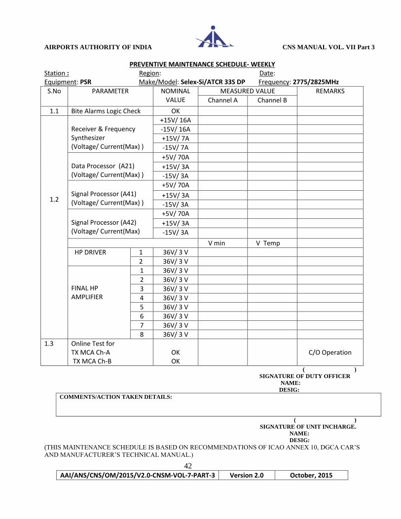
PREVENTIVE MAINTENANCE SCHEDULE- WEEKLY Station : Region: Date: Equipment: PSR Make/Model: Selex-Si/ATCR 33S DP Frequency: 2775/2825MHz
S.No PARAMETER NOMINAL VALUE
MEASURED VALUE REMARKS
Channel A Channel B
1.1 Bite Alarms Logic Check OK
1.2
Receiver & Frequency Synthesizer (Voltage/ Current(Max) )
+15V/ 16A
-15V/ 16A
+15V/ 7A
-15V/ 7A
Data Processor (A21) (Voltage/ Current(Max) )
+5V/ 70A
+15V/ 3A
-15V/ 3A
Signal Processor (A41) (Voltage/ Current(Max) )
+5V/ 70A
+15V/ 3A
-15V/ 3A
Signal Processor (A42) (Voltage/ Current(Max)
+5V/ 70A
+15V/ 3A
-15V/ 3A
V min V Temp
HP DRIVER 1 36V/ 3 V
2 36V/ 3 V
FINAL HP AMPLIFIER
1 36V/ 3 V
2 36V/ 3 V
3 36V/ 3 V
4 36V/ 3 V
5 36V/ 3 V
6 36V/ 3 V
7 36V/ 3 V
8 36V/ 3 V
1.3 Online Test for TX MCA Ch-A TX MCA Ch-B
OK OK
C/O Operation
( )
SIGNATURE OF DUTY OFFICER
NAME:
DESIG:
COMMENTS/ACTION TAKEN DETAILS:
( )
SIGNATURE OF UNIT INCHARGE.
NAME:
DESIG:
(THIS MAINTENANCE SCHEDULE IS BASED ON RECOMMENDATIONS OF ICAO ANNEX 10, DGCA CAR’S
AND MANUFACTURER’S TECHNICAL MANUAL.)

AIRPORTS AUTHORITY OF INDIA CNS MANUAL VOL. VII Part 3
43
AAI/ANS/CNS/OM/2015/V2.0-CNSM-VOL-7-PART-3 Version 2.0 October, 2015
PREVENTIVE MAINTENANCE SCHEDULE - MONTHLY Station : Region: Date: Equipment: PSR Make/Model: Selex-Si/ATCR 33S DPC Frequency: 2775/2825 MHZ PSR CHECKS
S.No
NAME OF THE CHECK
NOMINAL STATUS
ACTUAL STATUS REMARKS
Channel A Channel B
1.1 Programmability of Target Low/High beam selection
OK
1.2 Programmability of weather Low/High beam selection
OK
1.3 Programmability of Target STC Law OK
1.4 Programmability of weather STC Law OK
1.5
Weight Selection Map
OK
Operative Maps check
1.6 STAC & FDM OK
1.7 STEM Target OK
1.8 STEM Weather OK
1.9 ACOM Map OK
1.10 DBM Map OK
1.11 DCOM Map OK
1.12 CLM Map OK
1.13 FAN Map OK
1.14 Clutter Sensor map OK
1.15 Fine Doppler Map OK
1.16 Independent Weather Channel OK
1.17 Weather level Display OK
2.0 TX Assy. Blowers operation check OK
2.1 TTG Check OK ( )
SIGNATURE OF DUTY OFFICER
NAME:
DESIG:
COMMENTS/ACTION TAKEN DETAILS:
( )
SIGNATURE OF UNIT INCHARGE.
NAME:
DESIG:
(THIS MAINTENANCE SCHEDULE IS BASED ON RECOMMENDATIONS OF ICAO ANNEX 10, DGCA CAR’S
AND MANUFACTURER’S TECHNICAL MANUAL.)
AIRPORTS AUTHORITY OF INDIA CNS MANUAL VOL. VII Part 3
44
AAI/ANS/CNS/OM/2015/V2.0-CNSM-VOL-7-PART-3 Version 2.0 October, 2015
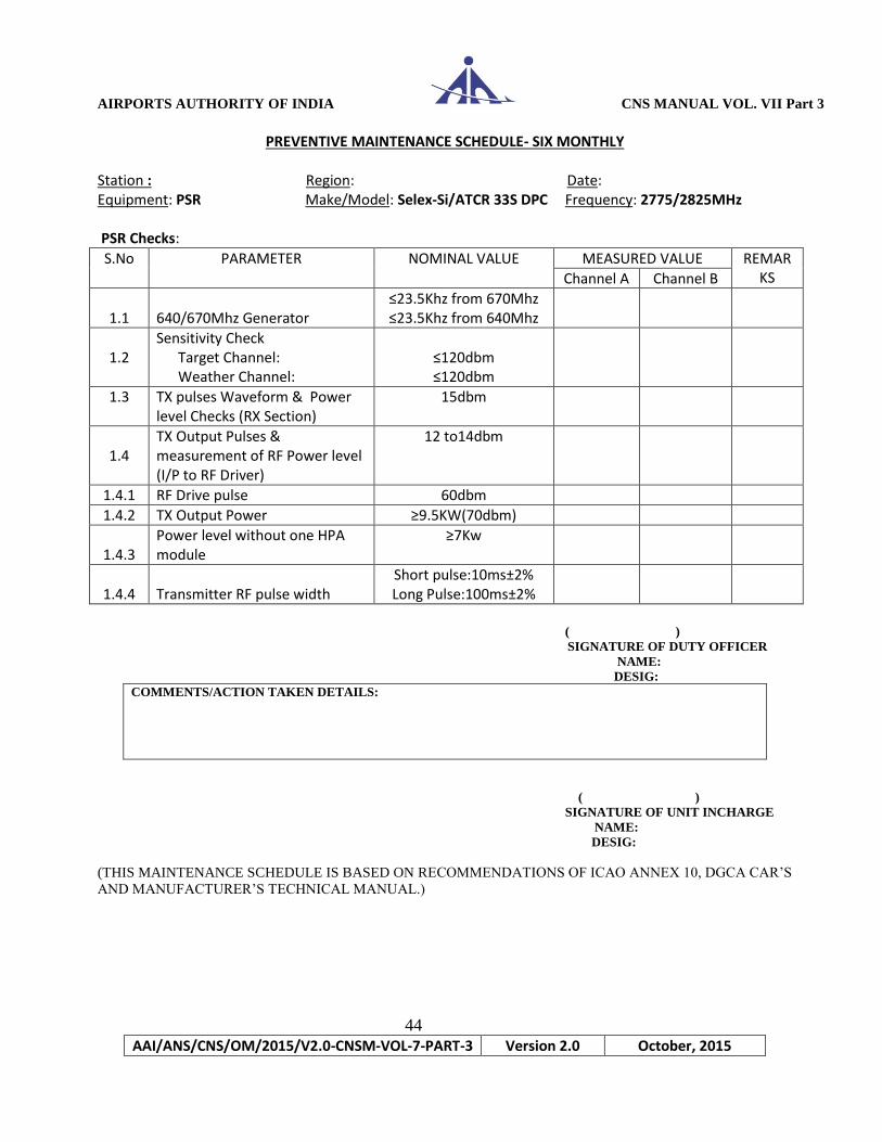
PREVENTIVE MAINTENANCE SCHEDULE- SIX MONTHLY Station : Region: Date: Equipment: PSR Make/Model: Selex-Si/ATCR 33S DPC Frequency: 2775/2825MHz PSR Checks:
S.No PARAMETER NOMINAL VALUE MEASURED VALUE REMARKS Channel A Channel B
1.1
640/670Mhz Generator
≤23.5Khz from 670Mhz ≤23.5Khz from 640Mhz
1.2
Sensitivity Check Target Channel: Weather Channel:
≤120dbm ≤120dbm
1.3 TX pulses Waveform & Power level Checks (RX Section)
15dbm
1.4
TX Output Pulses & measurement of RF Power level (I/P to RF Driver)
12 to14dbm
1.4.1 RF Drive pulse 60dbm
1.4.2 TX Output Power ≥9.5KW(70dbm)
1.4.3
Power level without one HPA module
≥7Kw
1.4.4
Transmitter RF pulse width
Short pulse:10ms±2% Long Pulse:100ms±2%
( )
SIGNATURE OF DUTY OFFICER
NAME:
DESIG:
COMMENTS/ACTION TAKEN DETAILS:
( )
SIGNATURE OF UNIT INCHARGE
NAME:
DESIG:
(THIS MAINTENANCE SCHEDULE IS BASED ON RECOMMENDATIONS OF ICAO ANNEX 10, DGCA CAR’S
AND MANUFACTURER’S TECHNICAL MANUAL.)
AIRPORTS AUTHORITY OF INDIA CNS MANUAL VOL. VII Part 3
45
AAI/ANS/CNS/OM/2015/V2.0-CNSM-VOL-7-PART-3 Version 2.0 October, 2015
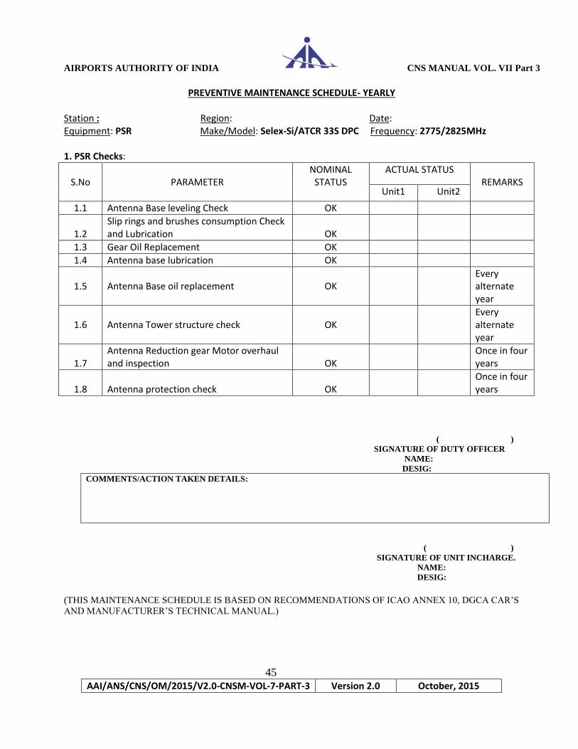
PREVENTIVE MAINTENANCE SCHEDULE- YEARLY Station : Region: Date: Equipment: PSR Make/Model: Selex-Si/ATCR 33S DPC Frequency: 2775/2825MHz 1. PSR Checks:
S.No
PARAMETER
NOMINAL STATUS
ACTUAL STATUS REMARKS
Unit1 Unit2
1.1 Antenna Base leveling Check OK
1.2
Slip rings and brushes consumption Check and Lubrication
OK
1.3 Gear Oil Replacement OK
1.4 Antenna base lubrication OK
1.5
Antenna Base oil replacement
OK
Every alternate year
1.6
Antenna Tower structure check
OK
Every alternate year
1.7
Antenna Reduction gear Motor overhaul and inspection
OK
Once in four years
1.8
Antenna protection check
OK
Once in four years
( )
SIGNATURE OF DUTY OFFICER
NAME:
DESIG:
COMMENTS/ACTION TAKEN DETAILS:
( )
SIGNATURE OF UNIT INCHARGE.
NAME:
DESIG:
(THIS MAINTENANCE SCHEDULE IS BASED ON RECOMMENDATIONS OF ICAO ANNEX 10, DGCA CAR’S
AND MANUFACTURER’S TECHNICAL MANUAL.)

AIRPORTS AUTHORITY OF INDIA CNS MANUAL VOL. VII Part 3
46
AAI/ANS/CNS/OM/2015/V2.0-CNSM-VOL-7-PART-3 Version 2.0 October, 2015
PREVENTIVE MAINTENANCE SCHEDULE- DAILY Station : Region: Date: Equipment: SSR Make/Model: Selex-Si/SIR-S Frequency: 1030MHz 1. General :
S.No PARAMETER STATUS REMARKS
1.1 General cleanliness of Eqpt room
1.2 Status of air conditioners AC1: AC2: AC3:
1.3 Equipment room temp(18±2°C)
1.4 Status of obstruction lights
1.5 Mains Power supply P-N(230V+/-10%)
1.6 UPS Status UPS1: UPS2:
1.7 Equipment switch board Status
1.8 Any unusual noise observed in Antenna Room
2. Front panel indications:
S.No PARAMETER NOMINAL STATUS REMARKS
Ch-A Ch-B
2.1
CHANGE OVER UNIT OK/Not OK OK/Not OK
Change Over DC Indicators should
glow Green
Relays
Fan
RPCM mismatch
TXRX1/TXRX2
2.2
PDA & OCP ASSY
PWR On Indicator should glow Green
Lamp test:
RPCM Fail/OVT Indicators should not Glow
RX Fail/OVT
TX Fail/OVT
2.3
RPCM PC Assembly
CPU
Indicators should glow Green
BFL/COM1
Indicator should glow Yellow
2.4
TXIP(A7)
General failure
Indicator should not glow
Radiation status Indicator should
glow steady Green
ON/OFF
CPU OK
Lamp test
AIRPORTS AUTHORITY OF INDIA CNS MANUAL VOL. VII Part 3
47
AAI/ANS/CNS/OM/2015/V2.0-CNSM-VOL-7-PART-3 Version 2.0 October, 2015
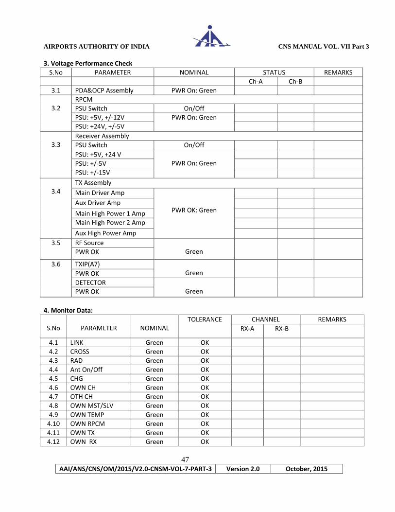
3. Voltage Performance Check
S.No PARAMETER NOMINAL STATUS REMARKS
Ch-A Ch-B
3.1 PDA&OCP Assembly PWR On: Green
3.2
RPCM
PSU Switch On/Off
PSU: +5V, +/-12V PWR On: Green
PSU: +24V, +/-5V
3.3
Receiver Assembly
PSU Switch On/Off
PSU: +5V, +24 V PWR On: Green
PSU: +/-5V
PSU: +/-15V
3.4
TX Assembly
Main Driver Amp
PWR OK: Green
Aux Driver Amp
Main High Power 1 Amp
Main High Power 2 Amp
Aux High Power Amp
3.5 RF Source Green
PWR OK
3.6 TXIP(A7) Green
PWR OK
DETECTOR Green
PWR OK
4. Monitor Data:
S.No
PARAMETER
NOMINAL
TOLERANCE CHANNEL REMARKS
RX-A RX-B
4.1 LINK Green OK
4.2 CROSS Green OK
4.3 RAD Green OK
4.4 Ant On/Off Green OK
4.5 CHG Green OK
4.6 OWN CH Green OK
4.7 OTH CH Green OK
4.8 OWN MST/SLV Green OK
4.9 OWN TEMP Green OK
4.10 OWN RPCM Green OK
4.11 OWN TX Green OK
4.12 OWN RX Green OK
AIRPORTS AUTHORITY OF INDIA CNS MANUAL VOL. VII Part 3
48
AAI/ANS/CNS/OM/2015/V2.0-CNSM-VOL-7-PART-3 Version 2.0 October, 2015
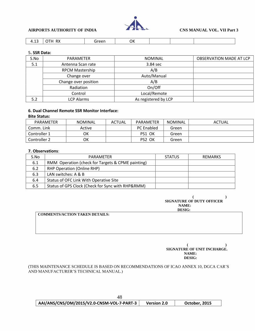
4.13 OTH RX Green OK
5. SSR Data:
S.No PARAMETER NOMINAL OBSERVATION MADE AT LCP
5.1 Antenna Scan rate 3.84 sec
RPCM Mastership A/B
Change over Auto/Manual
Change over position A/B
Radiation On/Off
Control Local/Remote
5.2 LCP Alarms As registered by LCP
6. Dual Channel Remote SSR Monitor Interface: Bite Status:
PARAMETER NOMINAL ACTUAL PARAMETER NOMINAL ACTUAL
Comm. Link Active PC Enabled Green
Controller 1 OK PS1 OK Green
Controller 2 OK PS2 OK Green
7. Observations:
S.No PARAMETER STATUS REMARKS
6.1 RMM Operation (check for Targets & CPME painting)
6.2 RHP Operation (Online RHP)
6.3 LAN switches: A & B
6.4 Status of OFC Link With Operative Site
6.5 Status of GPS Clock (Check for Sync with RHP&RMM)
( )
SIGNATURE OF DUTY OFFICER
NAME:
DESIG:
COMMENTS/ACTION TAKEN DETAILS:
( )
SIGNATURE OF UNIT INCHARGE.
NAME:
DESIG:
(THIS MAINTENANCE SCHEDULE IS BASED ON RECOMMENDATIONS OF ICAO ANNEX 10, DGCA CAR’S
AND MANUFACTURER’S TECHNICAL MANUAL.)
AIRPORTS AUTHORITY OF INDIA CNS MANUAL VOL. VII Part 3
49
AAI/ANS/CNS/OM/2015/V2.0-CNSM-VOL-7-PART-3 Version 2.0 October, 2015
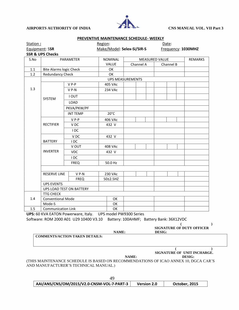
PREVENTIVE MAINTENANCE SCHEDULE- WEEKLY Station : Region: Date: Equipment: SSR Make/Model: Selex-Si/SIR-S Frequency: 1030MHZ SSR & UPS Checks
S.No PARAMETER NOMINAL VALUE
MEASURED VALUE REMARKS
Channel A Channel B
1.1 Bite Alarms logic Check OK
1.2 Redundancy Check OK
1.3
UPS MEASUREMENTS
SYSTEM
V P-P 405 VAc
V P-N 234 VAc
I OUT
LOAD
PKVA/PKW/PF
INT TEMP 20°C
RECTIFIER
V P-P 406 VAc
V DC 432 V
I DC
BATTERY
V DC 432 V
I DC
INVERTER
V OUT 408 VAc
VDC 432 V
I DC
FREQ 50.0 Hz
RESERVE LINE V P-N 230 VAc
FREQ 50±2.5HZ
UPS EVENTS
UPS LOAD TEST ON BATTERY
1.4
TTG CHECK
Conventional Mode OK
Mode-S OK
1.5 Communication Link OK
UPS: 60 KVA EATON Powerware, Italy. UPS model PW9300 Series Software: ROM 2000 A01 U29 10400 V3.10 Battery: 100AHMF; Battery Bank: 36X12VDC
( )
SIGNATURE OF DUTY OFFICER
NAME: DESIG:
COMMENTS/ACTION TAKEN DETAILS:
( )
SIGNATURE OF UNIT INCHARGE.
NAME: DESIG:
(THIS MAINTENANCE SCHEDULE IS BASED ON RECOMMENDATIONS OF ICAO ANNEX 10, DGCA CAR’S
AND MANUFACTURER’S TECHNICAL MANUAL.)

AIRPORTS AUTHORITY OF INDIA CNS MANUAL VOL. VII Part 3
50
AAI/ANS/CNS/OM/2015/V2.0-CNSM-VOL-7-PART-3 Version 2.0 October, 2015
PREVENTIVE MAINTENANCE SCHEDULE- MONTHLY Station : Region: Date: Equipment: SSR Make/Model: Selex-Si/SIRS Frequency: 1030MHz SSR Checks :
S.No
PARAMETER
NOMINAL VALUE
MEASURED VALUE REMARKS
Channel-A Channel-B
1.1 Cabinet Air filters replacement OK/ Not OK
1.2
Initial setting verification
OK/ Not Ok
( )
SIGNATURE OF DUTY OFFICER
NAME:
DESIG:
COMMENTS/ACTION TAKEN DETAILS:
( )
SIGNATURE OF UNIT INCHARGE.
NAME:
DESIG:
(THIS MAINTENANCE SCHEDULE IS BASED ON RECOMMENDATIONS OF ICAO ANNEX 10, DGCA CAR’S
AND MANUFACTURER’S TECHNICAL MANUAL.)

AIRPORTS AUTHORITY OF INDIA CNS MANUAL VOL. VII Part 3
51
AAI/ANS/CNS/OM/2015/V2.0-CNSM-VOL-7-PART-3 Version 2.0 October, 2015
PREVENTIVE MAINTENANCE SCHEDULE- SIX MONTHLY Station : Region: Date: Equipment: SSR Make/Model: Selex-Si/Sir-S Frequency: 1030MHz SSR Checks
S.No
PARAMETER
NOMINAL VALUE
MEASURED VALUE Remarks Channel A Channel B
1.1 Receiver Tangential sensitivity Check
1.2 Receiver frequency and Bandwidth
1.3 Transmitter Output power level 62dbm
1.4
TX output power selection and sectorization
1.5 Pulse spacing:P2 to P1 delay 2±0.05µs(All modes)
P3 to P1 delay 8 ±0.10µs(Mode3/A) 21 ±0.10µs (Mode C)
P4 toP3 delay 2±0.05µs
P5 to P2 delay 2.35±0.05µs wrt Sync. phase reversal
P6 toP2 delay 1.5±0.05 µs wrt Sync. Phase reversal
1.6 Pulse shape of Transmitter: Pulse P1,P2,P3,P5: 8±0.10 µs P4(Short):0.8±0.10µs P4(long):1.6±0.10 µs P6(short):16.25±0.25 µs P6(long)*:30.25±0.25 µs * for reference only
Rise time & decay time
2.0 Transmitter pulse power spectrum
2.1 TTG Check
2.2 Bite Check and Redundancy Check
2.3 VSWR check
2.4 Test Transponder POD 98% ( )
SIGNATURE OF DUTY OFFICER
NAME: DESIG:
COMMENTS/ACTION TAKEN DETAILS:
( )
SIGNATURE OF UNIT INCHARGE.
NAME: DESIG:
(THIS MAINTENANCE SCHEDULE IS BASED ON RECOMMENDATIONS OF ICAO ANNEX 10, DGCA CAR’S
AND MANUFACTURER’S TECHNICAL MANUAL.)

AIRPORTS AUTHORITY OF INDIA CNS MANUAL VOL. VII Part 3
52
AAI/ANS/CNS/OM/2015/V2.0-CNSM-VOL-7-PART-3 Version 2.0 October, 2015
PREVENTIVE MAINTENANCE SCHEDULE OF MSSR -DAILY
MAKE: INDRA MODEL : IRS 20MP/S
Station : Date :
Parameters to be
Checked
Normal
Status
Status
Observed
Remarks
1.0 General
1.0.1 Cleanliness Dust Free
1.0.2 Temp 18 - 22 Deg C
1.0.3 Equipment
Cleanliness
Dust Free
1.0.4 Obstruction Light Working Okay
1.1 On Line Transmitter CTT1 or CTT2 Observations on
SLG
1.1.1 Status of Online TX G / O / R
1.1.1.1 Status of SAU G / O / R
1.1.1.2 Status of SDU G / O / R
1.1.1.3 Status of TRA G / O / R
1.1.1.4 Status of EMU G / O / R
1.1.1.5 Status of CTU G / O / R
1.1.1.6 Status of TPS G / O / R
1.1.2 Status of Standby TX Y/ O / R
1.1.2.1 Status of SAU G / O / R
1.1.2.2 Status of SDU G / O / R
1.1.2.3 Status of TRA G / O / R
1.1.2.4 Status of EMU G / O / R
1.1.2.5 Status of CTU G / O / R
1.1.2.6 Status of TPS G / O / R
1.2 Status Ant. Motor1 G / O / R
1.3 Status Ant. Motor2 G / O / R
1.4 On Line Extractor MEX-MRU1
/MEX-MRU2
1.4.1 Status of Online
MEX-MRU
G / O / R
1.4.1.1 Status of MRU G / O / R
1.4.1.2 Status of MCPU G / O / R
1.4.1.3 Status of MICA 2 G / O / R
1.4.1.4 Status of MICA 3 G / O / R
1.4.1.5 Status of MFEX G / O / R

AIRPORTS AUTHORITY OF INDIA CNS MANUAL VOL. VII Part 3
53
AAI/ANS/CNS/OM/2015/V2.0-CNSM-VOL-7-PART-3 Version 2.0 October, 2015
( )
SIGN OF DUTY OFFICER
NAME:
DESIG:
COMMENTS/ACTION TAKEN DETAILS:
( )
SIGNATURE OF UNIT IN-CHARGE.
NAME:
DESIG:
(THIS MAINTENANCE SCHEDULE IS BASED ON RECOMMENDATIONS OF ICAO ANNEX 10, DGCA CAR’S
AND MANUFACTURER’S TECHNICAL MANUAL.)
1.4.1.6 Status of MVEX G / O / R
1.4.2 Status of S/By
MEX-MRU Y/ O / R
1.4.2.1 Status of MRU G / O / R
1.4.2.2 Status of MCPU G / O / R
1.4.2.3 Status of MICA 2 G / O / R
1.4.2.4 Status of MICA 3 G / O / R
1.4.2.5 Status of MFEX G / O / R
1.4.2.6 Status of MVEX G / O / R
1.5 External Signals
1.5.1 ACP1 G / O / R
1.5.2 ARP1 G / O / R
1.5.3 ACP2 G / O / R
1.5.4 ARP2 G / O / R
1.5.5 FFM G / O / R
1.5.6 UTC1 G / O / R
1.5.7 UTC2 G / O / R
1.6 Data Output Sources
1.6.1 Asterix 01 LAN/COM
1.6.2 Asterix 48 LAN/COM

AIRPORTS AUTHORITY OF INDIA CNS MANUAL VOL. VII Part 3
54
AAI/ANS/CNS/OM/2015/V2.0-CNSM-VOL-7-PART-3 Version 2.0 October, 2015
PREVENTIVE MAINTENANCE SCHEDULE OF MSSR – Monthly
MAKE : INDRA MODEL : IRS 20MP/S
Station : Date :
Parameters to be
Checked
Normal
Status
Status
observed
Remarks
1.0 General Inspection
1.0.1 Antenna Pedestal
1) No Oil Spillage
2) No Unusual sound
3) Fans operating Okay
1.0.2 All earth pits Clear of Grass/
Connections intact
1.1 Pedestal Control Box
1.1.1 Motor 1 oil level lamp Not lit
1.1.2 Motor 2 oil level lamp Not Lit
1.1.2 Push Test Lamp
Switch
All lamps lit
1.1.3 Check the Fan Operating okay
1.1.4 Out Put of PS1 24V +/- 1 V
1.1.5 Out Put of PS2 24V +/- 1 V
1.1.6 Out Put of PS3 24V +/- 1 V
1.1.7 Out Put of PS4 15V +/- 1 V
1.1.8 Out Put of PS5 15V +/- 1 V
1.1.9 Check Status of RV1
(AC discharges)
If Red Replace the
cartridge
1.1.10 Check Status of RV2
(AC discharges)
If Red Replace the
cartridge
1.1.11 Check Status of RV3
(AC discharges)
If Red Replace the
cartridge
1.1.12 Check all VDC
dischargers
Replace if any found
faulty
1.2 Mode-S Interrogator-I
1.2.1 TPS Voltages
+ 48 V +48V +/- 5V
+28 V +28V +/- 3 V
+ 15 V +15V +/- 1.5 V
+5 V +5V +/-0 .5 V

AIRPORTS AUTHORITY OF INDIA CNS MANUAL VOL. VII Part 3
55
AAI/ANS/CNS/OM/2015/V2.0-CNSM-VOL-7-PART-3 Version 2.0 October, 2015
COMMENTS/ACTION TAKEN DETAILS:
SIGN OF UNIT IN CHARGE. SIGN OF CNS IN CHARGE
NAME: NAME:
DESIGNATION: DESIGNATION:
(THIS MAINTENANCE SCHEDULE IS BASED ON RECOMMENDATIONS OF ICAO ANNEX 10, DGCA CAR’S
AND MANUFACTURER’S TECHNICAL MANUAL.)
- 15 V -15V +/- 1.5V
1.2.2 MEX Power Supplies
+ 5 V +5V +/- 0.5V
+ 12 V +12V +/- 1.2 V
- 12 V -12V +/- 1.2 V
+ 15 V +15V +/- 1.5 V
- 15 V -15V +/- 1.5 V
+ 3.3 V +3.3V +/- 0.2V
1.3 Mode-S Interrogator-II
1.3.1 TPS Voltages
+ 48 V +48V +/- 5V
+28 V +28V +/- 3 V
+ 15 V +15V +/- 1.5 V
+5 V +5V +/-0 .5 V
- 15 V -15V +/- 1.5V
1.3.2 MEX Power Supplies
+ 5 V +5V +/- 0.5V
+ 12 V +12V +/- 1.2 V
- 12 V -12V +/- 1.2 V
+ 15 V +15V +/- 1.5 V
- 15 V -15V +/- 1.5 V
+ 3.3 V +3.3V +/- 0.2V
1.4 Print outs
1.4.1 Site / Tracking Tab
1.4.2 GTC map Tab
1.4.3 Power Tab
1.4.4 Reflector Tab

AIRPORTS AUTHORITY OF INDIA CNS MANUAL VOL. VII Part 3
56
AAI/ANS/CNS/OM/2015/V2.0-CNSM-VOL-7-PART-3 Version 2.0 October, 2015
4.0 Extractor Antenna Interface Checks: Channel 2
4.1. Encoder 1
4.1.1 ARP Present Present
4.1.2 ACP Present Present
4.1.3 ACP per ARP 16384
4.2 Encoder 2
4.2.1 ARP Present Present
4.2.2 ACP Present Present
4.2.3 ACP per ARP 16384
PREVENTIVE MAINTENANCE SCHEDULE OF MSSR - Six Monthly
MAKE : INDRA MODEL : IRS 20MP/S
Station : Date :
Parameters to be
Checked
Normal
Status
Status
observed
Remarks
1.0 Monthly
Maintenance
Carried out
2.0 Frequency Checks
2.1 Transmission
Frequency Channel 1
1030 +/- .01
MHz
2.2 Transmission
Frequency Channel 2
1030 +/- 0.01 MHz
3.0 Extractor Antenna Interface Checks: Channel 1
3.1 Encoder 1
3.1.1 ARP Present Present
3.1.2 ACP Present Present
3.1.3 ACP per ARP 16384
3.2 Encoder 2
3.2.1 ARP Present Present
3.2.2 ACP Present Present
3.2.3 ACP per ARP 16384

AIRPORTS AUTHORITY OF INDIA CNS MANUAL VOL. VII Part 3
57
AAI/ANS/CNS/OM/2015/V2.0-CNSM-VOL-7-PART-3 Version 2.0 October, 2015
COMMENTS/ACTION TAKEN DETAILS:
SIGN OF UNIT IN CHARGE SIGN OF CNS INCHARGE
NAME: NAME:
DESIGNATION: DESIGNATION:
(THIS MAINTENANCE SCHEDULE IS BASED ON RECOMMENDATIONS OF ICAO ANNEX 10, DGCA CAR’S
AND MANUFACTURER’S TECHNICAL MANUAL.)
5.0 Reflector Map generation Channel - I
5.1 Reflector Generation Generated
5.2 Add the selected
Reflectors
Added
5.3 Manual reflectors Add if needed
6.0 Reflector Map generation Channel - II
6.1 Reflector Generation Reflector
Generation
6.2 Add the selected
Reflectors
Added
6.3 Manual reflectors Add if needed
7.0 Monopulse Curve Generation Channel - I
7.1 Generate the Curve Generated
7.2 Compare with main
Map
Identical
8.0 Monopulse Curve Generation Channel - II
8.1 Generate the Curve Generated
8.2 Compare with main
Map
Identical

AIRPORTS AUTHORITY OF INDIA CNS MANUAL VOL. VII Part 3
58
AAI/ANS/CNS/OM/2015/V2.0-CNSM-VOL-7-PART-3 Version 2.0 October, 2015
PREVENTIVE MAINTENANCE SCHEDULE OF MSSR – Annually
MAKE: INDRA MODEL : IRS 20MP/S
Station : Date :
Parameters to be
Checked
Normal
Status
Status
observed
Remarks
1.0 Monthly Maintenance Carried out
2.0 Six Monthly
Maintenance Carried out
3.0 Pedestal Checks
3.1 Bearing Ring greasing Carried out
3.2 Check oil level in
motor / gear box
Level OK
3.3 Check Pedestal fan OK
3.4 Check heater OK
3.5 Check Date of Last
Labyrinth Greasing
If more than 2 years
Grease
3.6 Check Date of Last
Mechanical AITS
Greasing
If more than 2 years
Grease
3.7 Check Date of
Motor/Gear Box Oil
Change/Greasing
If more than 2 years
Change oil/Grease the
bearings
3.8 Check condition of
Fans
Replace if required
3.9 Check condition of
pedestal seals Replace if required
4.0 Check Receiver Raw Video Output
4.1 Channel – I
4.1.1 Video Present at TP-
23 VS-MRU Present
4.1.2 Video Present at TP-
12 VO-MRU Present
4.1.3 Video Present at TP-6
VD-MRU Present
4.2 Channel - II
4.2.1 Video Present at TP-
23 VS-MRU Present
4.2.2 Video Present at TP-
12 VO-MRU Present
4.2.3 Video Present at TP-6
VD-MRU Present

AIRPORTS AUTHORITY OF INDIA CNS MANUAL VOL. VII Part 3
59
AAI/ANS/CNS/OM/2015/V2.0-CNSM-VOL-7-PART-3 Version 2.0 October, 2015
5.0 Measure Receiver Nominal Frequency
5.1 Channel - I
5.1.1 Sum 1090 +/- 0.5 MHz
5.1.2 Omni 1090 +/- 0.5 MHz
5.1.3 Difference 1090 +/- 0.5 MHz
5.2 Channel - II
5.2.1 Sum 1090 +/- 0.5 MHz
5.2.2 Omni 1090 +/- 0.5 MHz
5.2.3 Difference 1090 +/- 0.5 MHz
6.0 Measure the Receiver Bandwidth
6.1 Channel – I
6.1.1 SUM
6.1.1.1 At 3 dB
6.1.1.2 At 40 dB >/= 2.5 times at 3 dB
6.1.1.3 At 60 dB >/= 4.5 times at 3 dB
6.1.2 OMNI
6.1.2.1 At 3 dB > 8 MHz
6.1.2.2 At 40 dB >/= 2.5 times at 3 dB
6.1.2.3 At 60 dB >/= 4.5 times at 3 dB
6.1.3 DIFFERENCE
6.1.3.1 At 3 dB > 8 MHz
6.1.3.2 At 40 dB >/= 2.5 times at 3 dB
6.1.3.3 At 60 dB >/= 4.5 times at 3 dB
6.2 Channel – II
6.2.1 SUM
6.2.1.1 At 3 dB > 8 MHz
6.2.1.2 At 40 dB >/= 2.5 times at 3 dB
6.2.1.3 At 60 dB >/= 4.5 times at 3 dB
6.2.2 OMNI
6.2.2.1 At 3 dB > 8 MHz
6.2.2.2 At 40 dB >/= 2.5 times at 3 dB
6.2.2.3 At 60 dB >/= 4.5 times at 3 dB
6.2.3 DIFFERENCE
6.2.3.1 At 3 dB > 8 MHz
6.2.3.2 At 40 dB >/= 2.5 times at 3 dB
6.2.3.3 At 60 dB >/= 4.5 times at 3 dB
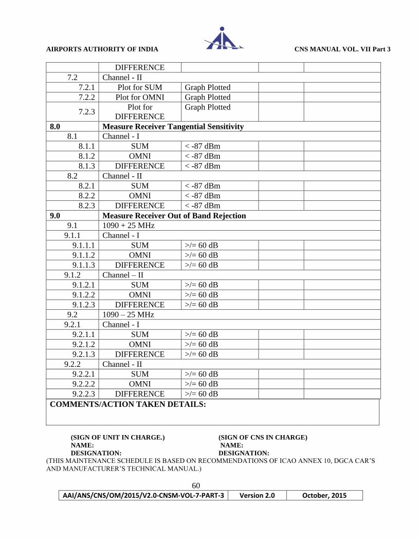
7.0 Measure the Receiver Dynamic Range
7.1 Channel - I
7.1.1 Plot for SUM Graph Plotted
7.1.2 Plot for OMNI Graph Plotted
7.1.3 Plot for Graph Plotted
AIRPORTS AUTHORITY OF INDIA CNS MANUAL VOL. VII Part 3
60
AAI/ANS/CNS/OM/2015/V2.0-CNSM-VOL-7-PART-3 Version 2.0 October, 2015
COMMENTS/ACTION TAKEN DETAILS:
(SIGN OF UNIT IN CHARGE.) (SIGN OF CNS IN CHARGE)
NAME: NAME:
DESIGNATION: DESIGNATION: (THIS MAINTENANCE SCHEDULE IS BASED ON RECOMMENDATIONS OF ICAO ANNEX 10, DGCA CAR’S
AND MANUFACTURER’S TECHNICAL MANUAL.)
DIFFERENCE
7.2 Channel - II
7.2.1 Plot for SUM Graph Plotted
7.2.2 Plot for OMNI Graph Plotted
7.2.3 Plot for
DIFFERENCE
Graph Plotted
8.0 Measure Receiver Tangential Sensitivity
8.1 Channel - I
8.1.1 SUM < -87 dBm
8.1.2 OMNI < -87 dBm
8.1.3 DIFFERENCE < -87 dBm
8.2 Channel - II
8.2.1 SUM < -87 dBm
8.2.2 OMNI < -87 dBm
8.2.3 DIFFERENCE < -87 dBm
9.0 Measure Receiver Out of Band Rejection
9.1 1090 + 25 MHz
9.1.1 Channel - I
9.1.1.1 SUM >/= 60 dB
9.1.1.2 OMNI >/= 60 dB
9.1.1.3 DIFFERENCE >/= 60 dB
9.1.2 Channel – II
9.1.2.1 SUM >/= 60 dB
9.1.2.2 OMNI >/= 60 dB
9.1.2.3 DIFFERENCE >/= 60 dB
9.2 1090 – 25 MHz
9.2.1 Channel - I
9.2.1.1 SUM >/= 60 dB
9.2.1.2 OMNI >/= 60 dB
9.2.1.3 DIFFERENCE >/= 60 dB
9.2.2 Channel - II
9.2.2.1 SUM >/= 60 dB
9.2.2.2 OMNI >/= 60 dB
9.2.2.3 DIFFERENCE >/= 60 dB
AIRPORTS AUTHORITY OF INDIA CNS MANUAL VOL. VII Part 3
61
AAI/ANS/CNS/OM/2015/V2.0-CNSM-VOL-7-PART-3 Version 2.0 October, 2015
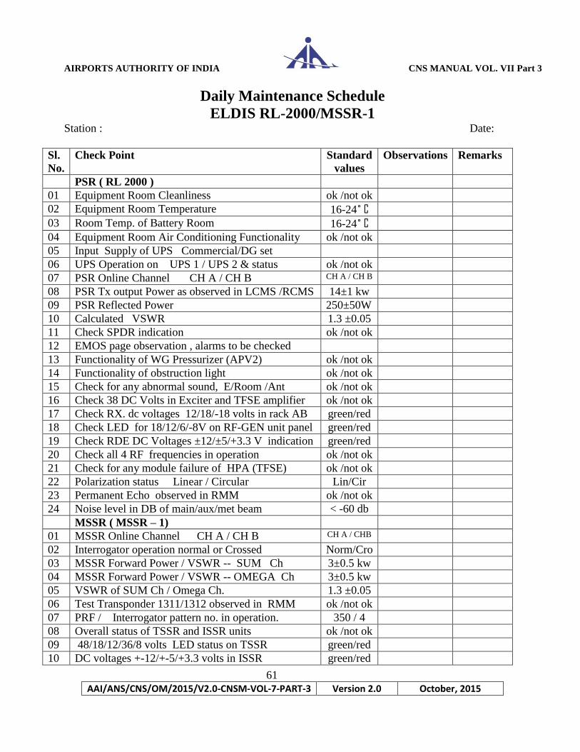
Daily Maintenance Schedule
ELDIS RL-2000/MSSR-1 Station : Date:
Sl.
No.
Check Point Standard
values
Observations Remarks
PSR ( RL 2000 )
01 Equipment Room Cleanliness ok /not ok
02 Equipment Room Temperature 16-24˚ C
03 Room Temp. of Battery Room 16-24˚ C
04 Equipment Room Air Conditioning Functionality ok /not ok
05 Input Supply of UPS Commercial/DG set
06 UPS Operation on UPS 1 / UPS 2 & status ok /not ok
07 PSR Online Channel CH A / CH B CH A / CH B
08 PSR Tx output Power as observed in LCMS /RCMS 14±1 kw
09 PSR Reflected Power 250±50W
10 Calculated VSWR 1.3 ±0.05
11 Check SPDR indication ok /not ok
12 EMOS page observation , alarms to be checked
13 Functionality of WG Pressurizer (APV2) ok /not ok
14 Functionality of obstruction light ok /not ok
15 Check for any abnormal sound, E/Room /Ant ok /not ok
16 Check 38 DC Volts in Exciter and TFSE amplifier ok /not ok
17 Check RX. dc voltages 12/18/-18 volts in rack AB green/red
18 Check LED for 18/12/6/-8V on RF-GEN unit panel green/red
19 Check RDE DC Voltages ±12/±5/+3.3 V indication green/red
20 Check all 4 RF frequencies in operation ok /not ok
21 Check for any module failure of HPA (TFSE) ok /not ok
22 Polarization status Linear / Circular Lin/Cir
23 Permanent Echo observed in RMM ok /not ok
24 Noise level in DB of main/aux/met beam < -60 db
MSSR ( MSSR – 1)
01 MSSR Online Channel CH A / CH B CH A / CHB
02 Interrogator operation normal or Crossed Norm/Cro
03 MSSR Forward Power / VSWR -- SUM Ch 3±0.5 kw
04 MSSR Forward Power / VSWR -- OMEGA Ch 3±0.5 kw
05 VSWR of SUM Ch / Omega Ch. 1.3 ±0.05
06 Test Transponder 1311/1312 observed in RMM ok /not ok
07 PRF / Interrogator pattern no. in operation. 350 / 4
08 Overall status of TSSR and ISSR units ok /not ok
09 48/18/12/36/8 volts LED status on TSSR green/red
10 DC voltages +-12/+-5/+3.3 volts in ISSR green/red

AIRPORTS AUTHORITY OF INDIA CNS MANUAL VOL. VII Part 3
62
AAI/ANS/CNS/OM/2015/V2.0-CNSM-VOL-7-PART-3 Version 2.0 October, 2015
REMARKS :
(THIS MAINTENANCE SCHEDULE IS BASED ON RECOMMENDATIONS OF ICAO ANNEX 10, DGCA CAR’S
AND MANUFACTURER’S TECHNICAL MANUAL.)
11 Noise figure of Sigma/Delta/Omega Channel < 3.0db
12 Connectivity of Mode S processor with other unit ok /not ok
13 ADS B Receiver Status ok /not ok
PSR & MSSR Standard
Values
Observations Remarks
01 Check any unusual sound from Antenna Cabin ok /not ok
02 Ant. Hut Room Temperature 15-50 °C
03 Inverter Power supply & output status ok /not ok
04 AILAN operating status including ACP/ARP status ok /not ok
05 NTP 1 &2 Servers operation status ok /not ok
06 Status of Eth Sw& M.C (Moxa) at Radar/APP ok /not ok
07 Antenna rotational speed 15 rpm
08 Status of APOID & OLTB block in Radar site / APP ok /not ok
09 Status of SCS switch in Radar and Ant. Hut ok /not ok
10 Status of LCMS/RCMS/RDP/SMP/RMM Processor ok /not ok
11 Status of Oil level in Antenna main gear > 80% > 80%
12 Recording process of PSR/MSSR data ok /not ok
13 Status OFC link and RF link from Radar to APP ok /not ok
14 PSR & MSSR data connectivity with ADP ok /not ok
15 Total count of ACP pulse from encoder 16384
16 ACP and ARP status green/red
Signature of Duty officer:
Name:
Designation: Date:
Signature of Unit-in-charge
Name:
Designation: Date:

AIRPORTS AUTHORITY OF INDIA CNS MANUAL VOL. VII Part 3
63
AAI/ANS/CNS/OM/2015/V2.0-CNSM-VOL-7-PART-3 Version 2.0 October, 2015
Daily Maintenance - UPS
Make: Model:
Station: Date:
SN Parameters Observation UPS-I Observation UPS-II
L1 L2 L3 L1 L2 L3
01 Output voltage(V)
230±5Vac
02 Output current(A) 20±5
A
03 Active power(KW) 5±2
kw
04 Reactive power(KVAr)
2±2kvar
05 Apparent power(KVA) 3-6
kva
06 Output power(%) 15±5
%
07 Rectifier voltage(V)
230±5Vac
08 Bypass voltage(V)
230±5Vac
09 Battery voltage(V)
295±10 V
10 Battery charge current(A)
11 Batt. discharge current(A)
12 Battery run time(HHMM)>2Hrs
13 Battery capacity (%) 100%
14 Frequency(Hz) 50±1 Hz
15 Bypass frequency(Hz) 50±1 Hz
16 Module temperature Inv. 38-50 °C
Remarks:
Signature of Duty officer:
Name:
Designation: Date:
Signature of Unit-in-charge
Name:
Designation: Date:
(THIS MAINTENANCE SCHEDULE IS BASED ON RECOMMENDATIONS OF ICAO ANNEX 10, DGCA CAR’S
AND MANUFACTURER’S TECHNICAL MANUAL.)

AIRPORTS AUTHORITY OF INDIA CNS MANUAL VOL. VII Part 3
64
AAI/ANS/CNS/OM/2015/V2.0-CNSM-VOL-7-PART-3 Version 2.0 October, 2015
Weekly Maintenance Schedule
ELDIS RL-2000/MSSR-1
Station : Date:
Sl.No. Check Point Observation Remarks
01 Antenna Cabin Cleanliness OK
02 Antenna Cabin Temperature 23 °C
03 Check the air filter condition in the cabin and clean it if
required or replaced it from stores.
Cleaned and
placed
04 Check any unusual sounds in the Antenna Cabin ,
equipment room and battery room and UPS
Nil
05 Check the oil level in the main /Aux. motor gear boxes OK
06 Check any oil leakage in main / Aux. gear boxes No leakage
07 Check the waste vessel of APV2 (wave guide
pressurizer) & excessive water shall be removed.
Water removed
08 Check antenna cabin fan M3 runs when temp > 30
degree and M3 & M4 both run when temp > 50 degree
Performed , OK
09 Check the transfer of radar data to display site through
OFC and RF link
Checked OK
10 Run the Main UPS from battery supply and check
battery voltages. Next week c/o to s/by ups and run from
battery supply and check battery voltages.
Performed OK
11 Functionality check of ventilation units (blower fans) in
all the equipment racks. Clean if required.
Performed OK
12 Check the functionality of all the modules of PSR
&MSSR and test transponders and monitor all
parameters from LCMS/RCMS.
All modules
found OK
13 Check the quality of targets from PSR, MSSR & ADS-
B. Check PEs, Test Transponder position in the RMM
and check noise/reflections/Spurious targets/splitting if
any and check any missing of targets in a scan and
check the range of targets for PSR & MSSR channel.
OK
PSR Transmitter page:- (LCMS or RCMS)
TEXC reading:-
On Line CH
Temperature Power measurement
A B C D
Forward Reverse Forward Reverse Forward Reverse Forward Reverse
AIRPORTS AUTHORITY OF INDIA CNS MANUAL VOL. VII Part 3
65
AAI/ANS/CNS/OM/2015/V2.0-CNSM-VOL-7-PART-3 Version 2.0 October, 2015
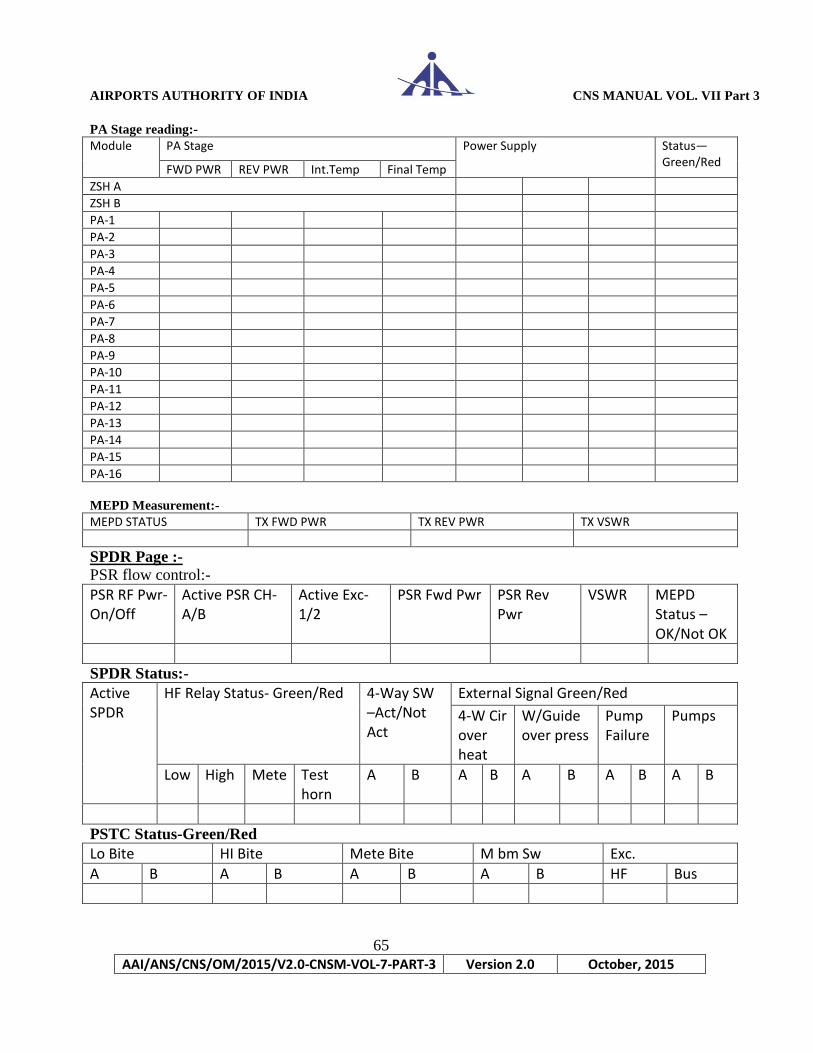
PA Stage reading:-
Module PA Stage Power Supply Status—Green/Red
FWD PWR REV PWR Int.Temp Final Temp
ZSH A
ZSH B
PA-1
PA-2
PA-3
PA-4
PA-5
PA-6
PA-7
PA-8
PA-9
PA-10
PA-11
PA-12
PA-13
PA-14
PA-15
PA-16
MEPD Measurement:-
MEPD STATUS TX FWD PWR TX REV PWR TX VSWR
SPDR Page :-
PSR flow control:-
PSR RF Pwr-On/Off
Active PSR CH-A/B
Active Exc-1/2
PSR Fwd Pwr PSR Rev Pwr
VSWR MEPD Status –OK/Not OK
SPDR Status:-
Active SPDR
HF Relay Status- Green/Red 4-Way SW –Act/Not Act
External Signal Green/Red
4-W Cir over heat
W/Guide over press
Pump Failure
Pumps
Low High Mete Test horn
A B A B A B A B A B
PSTC Status-Green/Red
Lo Bite HI Bite Mete Bite M bm Sw Exc.
A B A B A B A B HF Bus
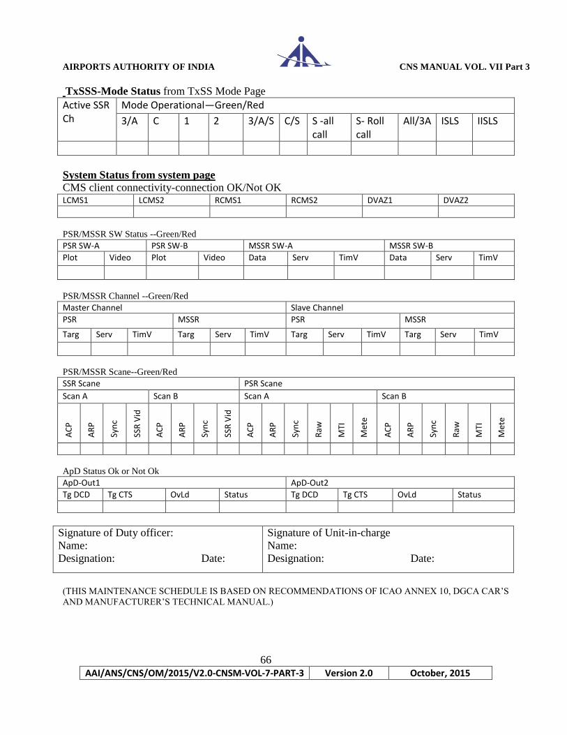
AIRPORTS AUTHORITY OF INDIA CNS MANUAL VOL. VII Part 3
66
AAI/ANS/CNS/OM/2015/V2.0-CNSM-VOL-7-PART-3 Version 2.0 October, 2015
TxSSS-Mode Status from TxSS Mode Page
Active SSR Ch
Mode Operational—Green/Red
3/A C 1 2 3/A/S C/S S -all call
S- Roll call
All/3A ISLS IISLS
System Status from system page
CMS client connectivity-connection OK/Not OK LCMS1 LCMS2 RCMS1 RCMS2 DVAZ1 DVAZ2
PSR/MSSR SW Status --Green/Red
PSR SW-A PSR SW-B MSSR SW-A MSSR SW-B
Plot Video Plot Video Data Serv TimV Data Serv TimV
PSR/MSSR Channel --Green/Red
Master Channel Slave Channel
PSR MSSR PSR MSSR
Targ Serv TimV Targ Serv TimV Targ Serv TimV Targ Serv TimV
PSR/MSSR Scane--Green/Red
SSR Scane PSR Scane
Scan A Scan B Scan A Scan B
AC
P
AR
P
Syn
c
SSR
Vid
AC
P
AR
P
Syn
c
SSR
Vid
AC
P
AR
P
Syn
c
Raw
MTI
Met
e
AC
P
AR
P
Syn
c
Raw
MTI
Met
e
ApD Status Ok or Not Ok
ApD-Out1 ApD-Out2
Tg DCD Tg CTS OvLd Status Tg DCD Tg CTS OvLd Status
Signature of Duty officer:
Name:
Designation: Date:
Signature of Unit-in-charge
Name:
Designation: Date:
(THIS MAINTENANCE SCHEDULE IS BASED ON RECOMMENDATIONS OF ICAO ANNEX 10, DGCA CAR’S
AND MANUFACTURER’S TECHNICAL MANUAL.)
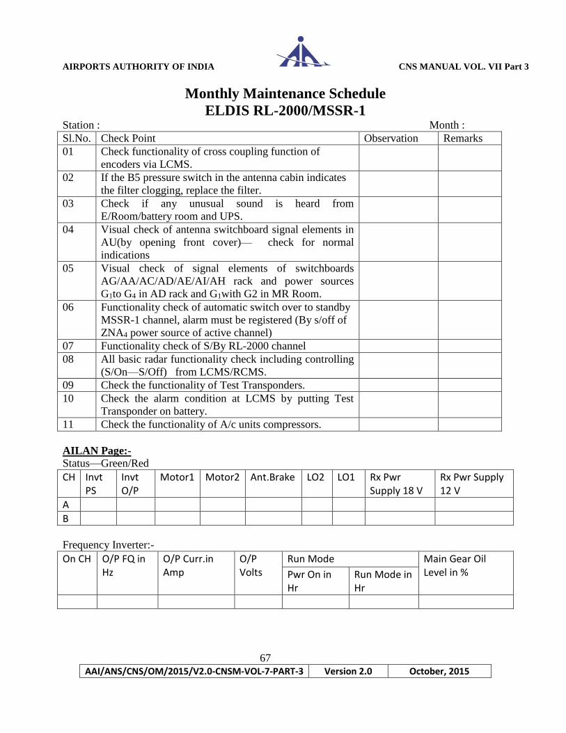
AIRPORTS AUTHORITY OF INDIA CNS MANUAL VOL. VII Part 3
67
AAI/ANS/CNS/OM/2015/V2.0-CNSM-VOL-7-PART-3 Version 2.0 October, 2015
Monthly Maintenance Schedule
ELDIS RL-2000/MSSR-1 Station : Month :
Sl.No. Check Point Observation Remarks
01 Check functionality of cross coupling function of
encoders via LCMS.
02 If the B5 pressure switch in the antenna cabin indicates
the filter clogging, replace the filter.
03 Check if any unusual sound is heard from
E/Room/battery room and UPS.
04 Visual check of antenna switchboard signal elements in
AU(by opening front cover)— check for normal
indications
05 Visual check of signal elements of switchboards
AG/AA/AC/AD/AE/AI/AH rack and power sources
G1to G4 in AD rack and G1with G2 in MR Room.
06 Functionality check of automatic switch over to standby
MSSR-1 channel, alarm must be registered (By s/off of
ZNA4 power source of active channel)
07 Functionality check of S/By RL-2000 channel
08 All basic radar functionality check including controlling
(S/On—S/Off) from LCMS/RCMS.
09 Check the functionality of Test Transponders.
10 Check the alarm condition at LCMS by putting Test
Transponder on battery.
11 Check the functionality of A/c units compressors.
AILAN Page:-
Status—Green/Red
CH Invt PS
Invt O/P
Motor1 Motor2 Ant.Brake LO2 LO1 Rx Pwr Supply 18 V
Rx Pwr Supply 12 V
A
B
Frequency Inverter:-
On CH O/P FQ in Hz
O/P Curr.in Amp
O/P Volts
Run Mode Main Gear Oil Level in % Pwr On in
Hr Run Mode in Hr

AIRPORTS AUTHORITY OF INDIA CNS MANUAL VOL. VII Part 3
68
AAI/ANS/CNS/OM/2015/V2.0-CNSM-VOL-7-PART-3 Version 2.0 October, 2015
Angle Information:-
CH Actual AI up dating or not
Rectification value
Max Deviation Value Main Deviation Value
A
B
AILAN Page:-
Antenna Rotation Speed :-
CH Rotation Speed in rot./min Revolution time in sec. Status Green/Red
Requested Measured Requested Measured ACP ARP
A
B
HF Relay Status—Green/Red:-
On CH SUM DIFF OMEGA
RF GEN-STC Page
STC Setting PSR CH
AUX BEAM MAIN BEAM METEO BEAM
Short Long Short Long Short Long
End (km)
Slope Db/dec
Depth db
End (km)
Slope Db/dec
Depth db
End (km)
Slope Db/dec
Depth db
End (km)
Slope Db/dec
Depth db
End (km)
Slope Db/dec
Depth db
End (km)
Slope Db/dec
Depth db
A
B
Rx Pwr Supply:-
PSR CH LOW BEAM HIGH BEAM METEO BEAM
+18 V +12 V -18 v +18 V +12 V -18 v +18 V +12 V -18 v
A
B
IF STAGE:-
AUX Beam:-
PSR CH
Noise Figure in db Noise Level in db Test Horn Pwr IF1 IF2 IF3 IF4 IF1 IF2 IF3 IF4
A
B
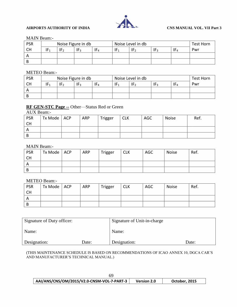
AIRPORTS AUTHORITY OF INDIA CNS MANUAL VOL. VII Part 3
69
AAI/ANS/CNS/OM/2015/V2.0-CNSM-VOL-7-PART-3 Version 2.0 October, 2015
MAIN Beam:-
PSR CH
Noise Figure in db Noise Level in db Test Horn Pwr IF1 IF2 IF3 IF4 IF1 IF2 IF3 IF4
A
B
METEO Beam:-
PSR CH
Noise Figure in db Noise Level in db Test Horn Pwr IF1 IF2 IF3 IF4 IF1 IF2 IF3 IF4
A
B
RF GEN-STC Page -- Other—Status Red or Green
AUX Beam:-
PSR CH
Tx Mode ACP ARP Trigger CLK AGC Noise Ref.
A
B
MAIN Beam:-
PSR CH
Tx Mode ACP ARP Trigger CLK AGC Noise Ref.
A
B
METEO Beam:-
PSR CH
Tx Mode ACP ARP Trigger CLK AGC Noise Ref.
A
B
Signature of Duty officer:
Name:
Designation: Date:
Signature of Unit-in-charge
Name:
Designation: Date:
(THIS MAINTENANCE SCHEDULE IS BASED ON RECOMMENDATIONS OF ICAO ANNEX 10, DGCA CAR’S
AND MANUFACTURER’S TECHNICAL MANUAL.)
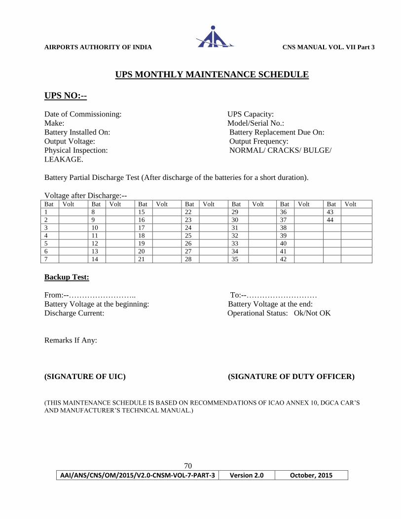
AIRPORTS AUTHORITY OF INDIA CNS MANUAL VOL. VII Part 3
70
AAI/ANS/CNS/OM/2015/V2.0-CNSM-VOL-7-PART-3 Version 2.0 October, 2015
UPS MONTHLY MAINTENANCE SCHEDULE
UPS NO:-- Date of Commissioning: UPS Capacity:
Make: Model/Serial No.:
Battery Installed On: Battery Replacement Due On:
Output Voltage: Output Frequency:
Physical Inspection: NORMAL/ CRACKS/ BULGE/
LEAKAGE.
Battery Partial Discharge Test (After discharge of the batteries for a short duration).
Voltage after Discharge:-- Bat Volt Bat Volt Bat Volt Bat Volt Bat Volt Bat Volt Bat Volt
1 8 15 22 29 36 43
2 9 16 23 30 37 44
3 10 17 24 31 38
4 11 18 25 32 39
5 12 19 26 33 40
6 13 20 27 34 41
7 14 21 28 35 42
Backup Test:
From:--…………………….. To:--………………………
Battery Voltage at the beginning: Battery Voltage at the end:
Discharge Current: Operational Status: Ok/Not OK
Remarks If Any:
(SIGNATURE OF UIC) (SIGNATURE OF DUTY OFFICER)
(THIS MAINTENANCE SCHEDULE IS BASED ON RECOMMENDATIONS OF ICAO ANNEX 10, DGCA CAR’S
AND MANUFACTURER’S TECHNICAL MANUAL.)

AIRPORTS AUTHORITY OF INDIA CNS MANUAL VOL. VII Part 3
71
AAI/ANS/CNS/OM/2015/V2.0-CNSM-VOL-7-PART-3 Version 2.0 October, 2015
Six-Monthly Maintenance Schedule
ELDIS RL-2000/MSSR-1 Station : Month :
Sl.No. Check Point Observation Remarks
01 Check the oil level in the main gear box and
Aux motor gearboxes and check any oil
leakage
02 Perform horizontal leveling of antenna at
equipment assembly. Check and possible
readjustment shall be carried out.
03 Perform lubrication of internal and external
O- ring/gasket.
04 Check the performance of thermostat ST2 for
M3 fan and Thermostat ST3 for M4 fan
(with the help of hot air gun)
05 Check the Antenna Cabin air filter condition
(open filter box lid) clean it up or replace.
06 Functionality check of motor de-blocking
switch Q1 (Unblocking Rotation switch) in
antenna switchboard
07 Check the blocking contact of antenna limit
switch S2 in ant cabin by releasing of an
locking peg from its wall holder.
08 Antenna unit – Check unusual sounds,
running irregularity, increased noise etc.
09 Visual check of antenna switchboard signal
elements in AU (by opening front cover)—all
must be lightning.
10 Performance check of the S3 rotation locking
contact(Ladder Limit Switch)
11 Visual check of signal elements of
switchboards AG/AA/AC/AD/AE/AI/AH
rack and power sources G1until G4 in AD rack
and G1with G2
12 Check the function of radar current protectors
in main switch board by pressing check
button on body of current protector.

AIRPORTS AUTHORITY OF INDIA CNS MANUAL VOL. VII Part 3
72
AAI/ANS/CNS/OM/2015/V2.0-CNSM-VOL-7-PART-3 Version 2.0 October, 2015
Sl.No. Check Point Observation Remarks
13. Check of the APV2 over-pressure aggregate—
switch on/off pressure limits, compressor
operating period for the route standard
pressure.
Continued….
14 Check all the ventilators /Fan in rack AB to
AF (EPS block) AH & AI racks, ILANs,
Frequency converters, Computers rack, RF
Gen and RDEs – include eventual failure fan
diagnostic.
15 Functionality check of all indication lights on
radar switch boards (including indicators of
fuses, relays, source etc.)
16 Status check of grounding radar system
focused to connection points.
17 Check the transmission pulse shape of PSR
and MSSR
18 Check the peak power of transmission pulses
of PSR and MSSR
19 Check the earth resistances of all the seven
earth pits. Including grilled resistance
20 Check all the nuts and bolts of antenna system
and all connectors of equipments. Tighten if
found any loose contact.
21 Check warning sound from the hooter before
antenna starts rotation.
Signature of Duty officer:
Name:
Designation: Date:
Signature of Unit-in-charge
Name:
Designation: Date:
(THIS MAINTENANCE SCHEDULE IS BASED ON RECOMMENDATIONS OF ICAO ANNEX 10, DGCA CAR’S
AND MANUFACTURER’S TECHNICAL MANUAL.)
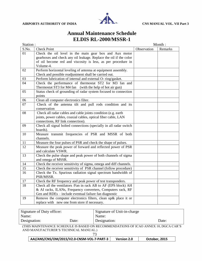
AIRPORTS AUTHORITY OF INDIA CNS MANUAL VOL. VII Part 3
73
AAI/ANS/CNS/OM/2015/V2.0-CNSM-VOL-7-PART-3 Version 2.0 October, 2015
Annual Maintenance Schedule
ELDIS RL-2000/MSSR-1 Station : Month : S.No. Check Point Observation Remarks
01 Check the oil level in the main gear box and Aux motor
gearboxes and check any oil leakage. Replace the oil if the color
of oil become red and viscosity is less, as per procedure in
Volume-4.
02 Perform horizontal leveling of antenna at equipment assembly.
Check and possible readjustment shall be carried out.
03 Perform lubrication of internal and external O- ring/gasket.
04 Check the performance of thermostat ST2 for M3 fan and
Thermostat ST3 for M4 fan (with the help of hot air gun)
05 Status check of grounding of radar system focused to connection
points
06 Clean all computer electronics filter.
07 Check of the antenna tilt and pull rods condition and its
conservation
08 Check all radar cables and cable joints condition (e.g. earth
joints, power cables, coaxial cables, optical fiber cable, LAN
connections, RF link connection).
09 Check all signal bolted connections (specially in all radar switch
boards).
10 Measure transmit frequencies of PSR and MSSR of both
channels.
11 Measure the four pulses of PSR and check the shape of pulses.
12 Measure the peak power of forward and reflected power of PSR
and calculate VSWR.
13 Check the pulse shape and peak power of both channels of sigma
and omega of MSSR.
14 Check the receiver sensitivity of sigma, omega and diff channels.
15 Check the receiver sensitivity of PSR channel (follow procedure)
16 Check the Tx. Spurious radiation signal spectrum bandwidth of
PSR/MSSR.
17 Check the RF frequency and peak power of test transponders.
18 Check all the ventilators /Fan in rack AB to AF (EPS block) AH
& AI racks, ILANs, Frequency converters, Computers rack, RF
Gen and RDEs – include eventual failure fan diagnostic
19 Remove the computer electronics filters, clean up& place it or
replace with new one from store if necessary.
Signature of Duty officer:
Name:
Designation: Date:
Signature of Unit-in-charge
Name:
Designation: Date:
(THIS MAINTENANCE SCHEDULE IS BASED ON RECOMMENDATIONS OF ICAO ANNEX 10, DGCA CAR’S
AND MANUFACTURER’S TECHNICAL MANUAL.)

AIRPORTS AUTHORITY OF INDIA CNS MANUAL VOL. VII Part 3
74
AAI/ANS/CNS/OM/2015/V2.0-CNSM-VOL-7-PART-3 Version 2.0 October, 2015
Chapter -4
Maintenance Schedules
ASMGCS
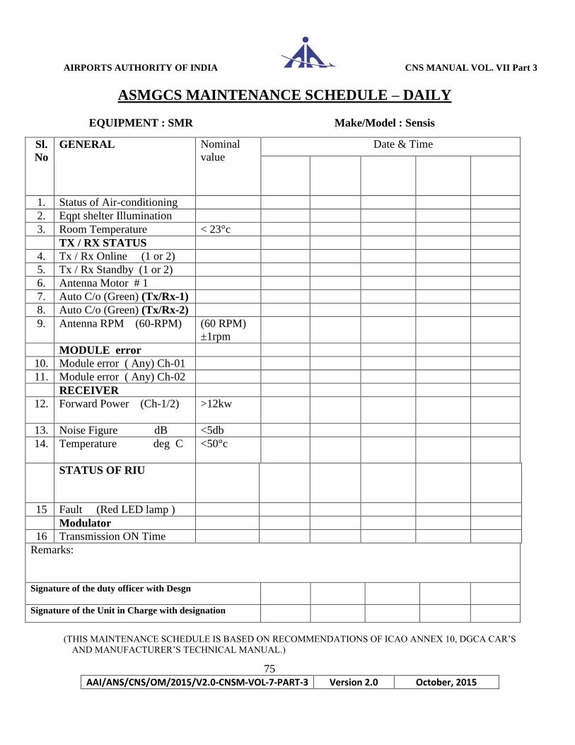
AIRPORTS AUTHORITY OF INDIA CNS MANUAL VOL. VII Part 3
75
AAI/ANS/CNS/OM/2015/V2.0-CNSM-VOL-7-PART-3 Version 2.0 October, 2015
ASMGCS MAINTENANCE SCHEDULE – DAILY
EQUIPMENT : SMR Make/Model : Sensis
(THIS MAINTENANCE SCHEDULE IS BASED ON RECOMMENDATIONS OF ICAO ANNEX 10, DGCA CAR’S
AND MANUFACTURER’S TECHNICAL MANUAL.)
Sl.
No
GENERAL
Nominal
value
Date & Time
1. Status of Air-conditioning
2. Eqpt shelter Illumination
3. Room Temperature < 23°c
TX / RX STATUS
4. Tx / Rx Online (1 or 2)
5. Tx / Rx Standby (1 or 2)
6. Antenna Motor # 1
7. Auto C/o (Green) (Tx/Rx-1)
8. Auto C/o (Green) (Tx/Rx-2)
9. Antenna RPM (60-RPM) (60 RPM)
±1rpm
MODULE error
10. Module error ( Any) Ch-01
11. Module error ( Any) Ch-02
RECEIVER
12. Forward Power (Ch-1/2)
>12kw
13. Noise Figure dB <5db
14.
Temperature deg C <50°c
STATUS OF RIU
15 Fault (Red LED lamp )
Modulator
16 Transmission ON Time
Remarks:
Signature of the duty officer with Desgn
Signature of the Unit in Charge with designation
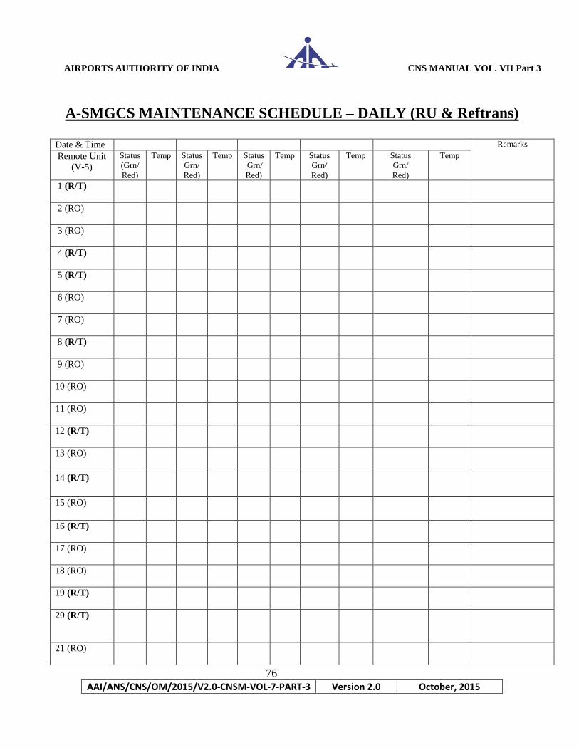
AIRPORTS AUTHORITY OF INDIA CNS MANUAL VOL. VII Part 3
76
AAI/ANS/CNS/OM/2015/V2.0-CNSM-VOL-7-PART-3 Version 2.0 October, 2015
A-SMGCS MAINTENANCE SCHEDULE – DAILY (RU & Reftrans)
Date & Time Remarks
Remote Unit
(V-5)
Status
(Grn/
Red)
Temp Status
Grn/
Red)
Temp Status
Grn/
Red)
Temp Status
Grn/
Red)
Temp Status
Grn/
Red)
Temp
1 (R/T)
2 (RO)
3 (RO)
4 (R/T)
5 (R/T)
6 (RO)
7 (RO)
8 (R/T)
9 (RO)
10 (RO)
11 (RO)
12 (R/T)
13 (RO)
14 (R/T)
15 (RO)
16 (R/T)
17 (RO)
18 (RO)
19 (R/T)
20 (R/T)
21 (RO)

AIRPORTS AUTHORITY OF INDIA CNS MANUAL VOL. VII Part 3
77
AAI/ANS/CNS/OM/2015/V2.0-CNSM-VOL-7-PART-3 Version 2.0 October, 2015
22 (RO)
23 (RO)
Reftrans -1
Reftrans -2
Reftrans -3
Reftrans -4
Sign &
Desgn
Sign of UIC
(THIS MAINTENANCE SCHEDULE IS BASED ON RECOMMENDATIONS OF ICAO ANNEX 10, DGCA CAR’S
AND MANUFACTURER’S TECHNICAL MANUAL.)

AIRPORTS AUTHORITY OF INDIA CNS MANUAL VOL. VII Part 3
78
AAI/ANS/CNS/OM/2015/V2.0-CNSM-VOL-7-PART-3 Version 2.0 October, 2015
A-SMGCS MAINTENANCE SCHEDULE –WEEKLY EQUIPMENT : SMR Make/Model : Sensis DATE Sl.N
o
Task to be Performed Nominal
Value
1 GENERAL
1.1 Equipment Cleanliness
1.2 Status of Air-conditioning
1.3 Eqpt shelter Illumination
1.4 Room Temperature
2 TX / RX STATUS
2.1 Tx / Rx Online (1 or 2)
2.2 Tx / Rx Standby (1 or 2)
2.3 Antenna Motor # 1 ON
2.4 Auto C/o (Green) (Tx/Rx-1) Green
2.5 Auto C/o (Green) (Tx/Rx-2) Green
3 BITE Rx/
Tx-1
Rx /
TX-
2
Rx/
Tx-1
Rx
/
TX
-2
Rx/
Tx-1
Rx /
TX-
2
Rx/
Tx-1
Rx /
TX-2
3.1 M / BOARD POWER
3.1.1 -15V -15 +/-
0.75
3.1.2 -5V -5 +/-
0.25
3.1.3 +28V 28 +/- 1
3.1.4 +48V 48 +/-
1V
3.1.5 +5V Encoder 5 +/-
0.25V
3.1.6 +5V Pilot 5 +/-
0.25V
3.1.7 +5V 5 +/-
0.25V
3.1.8 +15V 15 +/-
0.75V
3.1.9 Antenna RPM (60-RPM) 60 +/-
1%
3.1.1
0
Mains on-time (Hrs)
Rx/
Tx-1
Rx /
TX-
2
Rx/
Tx-1
Rx
/
TX
-2
Rx/
Tx-1
Rx /
TX-2
Rx/
Tx-1
Rx /
TX-2
3.2 MODULATOR A B A B A B A B A B A B A B A B
3.2.1 Mod Mean Current (mA) ----
3.2.2 Mod High Voltage (V) Nom
Value
+/- 50 V
3.2.3 Temperature Switch © <30 deg

AIRPORTS AUTHORITY OF INDIA CNS MANUAL VOL. VII Part 3
79
AAI/ANS/CNS/OM/2015/V2.0-CNSM-VOL-7-PART-3 Version 2.0 October, 2015
C
3.2.4 Temperature Conv. © <30 deg
C
3.2.5 Filament On-time (Hrs)
3.2.6 Tx On-time (Hrs)
DATE
Rx/
Tx-1
Rx /
TX-
2
Rx/
Tx-1
Rx
/
TX
-2
Rx/
Tx-1
Rx /
TX-2
Rx/
Tx-1
Rx
/TX-2
3.3 RECEIVER Nom.
Val.
A B A B A B A B A B A B A B A B
3.3.1 Forward Power KW >10kw
3.3.2 Noise Figure dB <5db
3.3.3 AFC Error Voltage V <0.04
3.3.4 V-Lo V < +-0.04
3.3.5 Temperature C <50°c
3.4 MOTOR CONTROLLER
3.4.1 Output Frequency
(Hz)
51
±0.1Hz
3.4.2 Current
(Amp)
3.9
±0.1A
3.4.3 Momentum (%) Nom.
Value
0.1%
3.4.4 Power
(KW)
Nom
Value
+/-
0.1kw
3.4.5 Output Voltage (V) Nom
Value
±1v
3.4.6 Runtime
(Hrs)
3.4.7 KWh Counter
(Kwh)
3.4.8 ACS Temperature C
3.5 RSD
3.5.1 PWB Temperature (C) <85°c
3.5.2 +48 Volt ±1v
3.6 TC3
3.6.1 Power On-time (Hrs)
3.7 VP3
3.7.1 FPGA Temperature (C ) <85°c
4.0 MODULE ERROR
4.0.1 TC 3 NIL
4.0.2 MOD-A NIL
4.0.3 RX-A NIL

AIRPORTS AUTHORITY OF INDIA CNS MANUAL VOL. VII Part 3
80
AAI/ANS/CNS/OM/2015/V2.0-CNSM-VOL-7-PART-3 Version 2.0 October, 2015
(THIS MAINTENANCE SCHEDULE IS BASED ON RECOMMENDATIONS OF ICAO ANNEX 10, DGCA CAR’S
AND MANUFACTURER’S TECHNICAL MANUAL.)
4.0.4 VP3 NIL
MODULE ERROR Nominal
Value
4.0.5 Mother Board Power Supply Green
4.0.6 RSD Green
4.0.7 Motor Controller Green
4.0.8 Com - 0 Green
4.0.9 Com - 1 Green
4.0.1
0
Com – 2 Green
4.0.1
1
Com – 3 Green
4.0.1
2
CAN Slave Green
4.0.1
3
CAN External Green
5.0 WAVE GUIDE
DEHYDRATOR
50.1 Outlet Pressure (in millibar)
5.0.2 Run time (Hrs)
5.0.3 Status of Dehydrater Pale Blue
6.0 STATUS OF RIU T
O
P
BO
TT
OM
T
O
P
BO
TT
OM
T
O
P
BO
TT
OM
T
O
p
BO
TT
OM
6.0.1 Power (Green LED) Green
6.0.2 ARP (Green LED ) Grn
Flashing
6.0.3 ACP (Green LED) Green
6.0.4 Trigger (Green LED) Grn
Flashing
6.0.5 Fault (No lamp ) OFF
Remarks
Signature of the duty officer
Signature of Unit In-charge
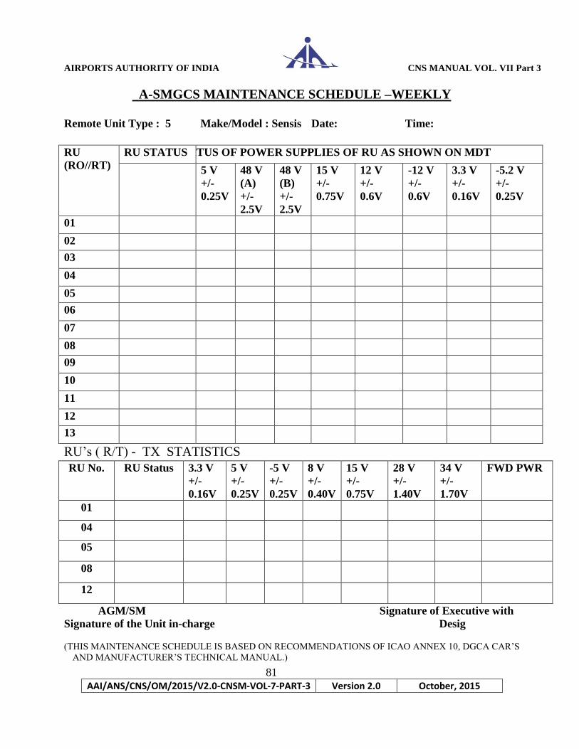
AIRPORTS AUTHORITY OF INDIA CNS MANUAL VOL. VII Part 3
81
AAI/ANS/CNS/OM/2015/V2.0-CNSM-VOL-7-PART-3 Version 2.0 October, 2015
A-SMGCS MAINTENANCE SCHEDULE –WEEKLY
Remote Unit Type : 5 Make/Model : Sensis Date: Time:
RU’s ( R/T) - TX STATISTICS
AGM/SM Signature of Executive with
Signature of the Unit in-charge Desig
(THIS MAINTENANCE SCHEDULE IS BASED ON RECOMMENDATIONS OF ICAO ANNEX 10, DGCA CAR’S
AND MANUFACTURER’S TECHNICAL MANUAL.)
RU
(RO//RT)
RU STATUS STATUS OF POWER SUPPLIES OF RU AS SHOWN ON MDT
5 V
+/-
0.25V
48 V
(A)
+/-
2.5V
48 V
(B)
+/-
2.5V
15 V
+/-
0.75V
12 V
+/-
0.6V
-12 V
+/-
0.6V
3.3 V
+/-
0.16V
-5.2 V
+/-
0.25V
01
02
03
04
05
06
07
08
09
10
11
12
13
RU No. RU Status 3.3 V
+/-
0.16V
5 V
+/-
0.25V
-5 V
+/-
0.25V
8 V
+/-
0.40V
15 V
+/-
0.75V
28 V
+/-
1.40V
34 V
+/-
1.70V
FWD PWR
01
04
05
08
12
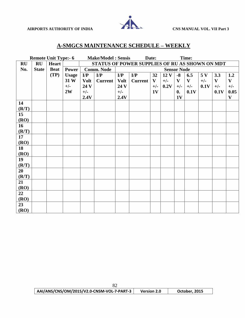
AIRPORTS AUTHORITY OF INDIA CNS MANUAL VOL. VII Part 3
82
AAI/ANS/CNS/OM/2015/V2.0-CNSM-VOL-7-PART-3 Version 2.0 October, 2015
A-SMGCS MAINTENANCE SCHEDULE – WEEKLY
Remote Unit Type:- 6 Make/Model : Sensis Date: Time:
RU
No.
RU
State
Heart
Beat
(TP)
STATUS OF POWER SUPPLIES OF RU AS SHOWN ON MDT
Power
Usage
31 W
+/-
2W
Comm. Node Sensor Node
I/P
Volt
24 V
+/-
2.4V
I/P
Current
I/P
Volt
24 V
+/-
2.4V
I/P
Current
32
V
+/-
1V
12 V
+/-
0.2V
-8
V
+/-
0.
1V
6.5
V
+/-
0.1V
5 V
+/-
0.1V
3.3
V
+/-
0.1V
1.2
V
+/-
0.05
V
14
(R/T)
15
(RO)
16
(R/T)
17
(RO)
18
(RO)
19
(R/T)
20
(R/T)
21
(RO)
22
(RO)
23
(RO)

AIRPORTS AUTHORITY OF INDIA CNS MANUAL VOL. VII Part 3
83
AAI/ANS/CNS/OM/2015/V2.0-CNSM-VOL-7-PART-3 Version 2.0 October, 2015
RU
No.
FPGA
Temp
Control
Board
Temp
Tx
Board
Temp
Cabinet
Temp
AGC Avg. FWD
Power for Tx
only (54 dBm)
VSWR
Ratio
Remarks
14
(R/T)
15
(RO)
16
(R/T)
17
(RO)
18
(RO)
19
(R/T)
20
(R/T)
21
(RO)
22
(RO)
23
(RO)
AGM / SM
Signature of Unit In-charge Signature of Executive
with Designation
(THIS MAINTENANCE SCHEDULE IS BASED ON RECOMMENDATIONS OF ICAO ANNEX 10, DGCA CAR’S
AND MANUFACTURER’S TECHNICAL MANUAL.)
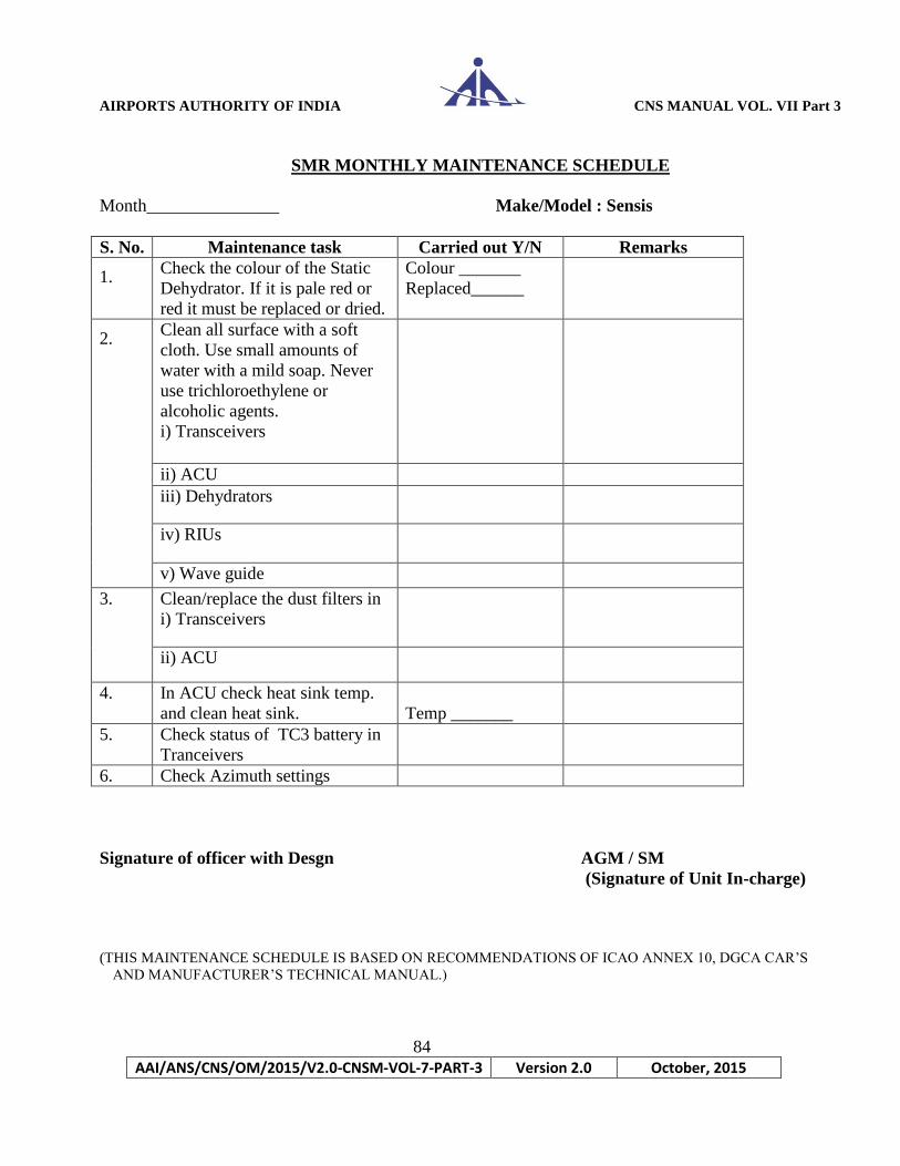
AIRPORTS AUTHORITY OF INDIA CNS MANUAL VOL. VII Part 3
84
AAI/ANS/CNS/OM/2015/V2.0-CNSM-VOL-7-PART-3 Version 2.0 October, 2015
SMR MONTHLY MAINTENANCE SCHEDULE
Month_______________ Make/Model : Sensis
S. No. Maintenance task Carried out Y/N Remarks
1. Check the colour of the Static
Dehydrator. If it is pale red or
red it must be replaced or dried.
Colour _______
Replaced______
2. Clean all surface with a soft
cloth. Use small amounts of
water with a mild soap. Never
use trichloroethylene or
alcoholic agents.
i) Transceivers
ii) ACU
iii) Dehydrators
iv) RIUs
v) Wave guide
3.
Clean/replace the dust filters in
i) Transceivers
ii) ACU
4. In ACU check heat sink temp.
and clean heat sink.
Temp _______
5. Check status of TC3 battery in
Tranceivers
6. Check Azimuth settings
Signature of officer with Desgn AGM / SM
(Signature of Unit In-charge)
(THIS MAINTENANCE SCHEDULE IS BASED ON RECOMMENDATIONS OF ICAO ANNEX 10, DGCA CAR’S
AND MANUFACTURER’S TECHNICAL MANUAL.)

AIRPORTS AUTHORITY OF INDIA CNS MANUAL VOL. VII Part 3
85
AAI/ANS/CNS/OM/2015/V2.0-CNSM-VOL-7-PART-3 Version 2.0 October, 2015
MONTHLY MAINTENANCE SCHEDULE ASMGCS PROCESSORS
Month___________ Date: Time: Make/Model : Sensis
1. Cleaning and dusting of all the processors are to be done.
2. Ensure that all connections are in place.
3. Check that unit’s intake and exhaust vents are not blocked with dust or debris.
Name of Processor Cleaning and Dusting carried out Remarks
RDP 1
RDP 2
RDP 3
RDP 4
TP 1
TP 2
MSDP 1
MSDP 2
DP 1
DP 2
DP 3
DP 4
DP 5
MDT
TEST System
MSDP
TP
MDT
DP
Processor MSDP 1 & 2 TP 1 & 2 MDT DP 1,2,3,4,5 RDP 1,2,3,4
Disk space
checking/cleaning
Log file checking
Processes
checking
(AGM/SM)
Signature of Unit In charge Signature of the Executive with Desig. (THIS MAINTENANCE SCHEDULE IS BASED ON RECOMMENDATIONS OF ICAO ANNEX 10, DGCA CAR’S
AND MANUFACTURER’S TECHNICAL MANUAL.)

AIRPORTS AUTHORITY OF INDIA CNS MANUAL VOL. VII Part 3
86
AAI/ANS/CNS/OM/2015/V2.0-CNSM-VOL-7-PART-3 Version 2.0 October, 2015
MONTHLY MAINTENANCE SCHEDULE
CONTROLLER WORKING POSITION
Display:
1. As needed, clean the display surface using a soft cloth chamois dampened with a
small amount of de-ionized water or isopropyl alcohol.
2. Dry immediately.
NOTE
Do not touch the display surface with your bare hands.
Do not wipe the display surface with a dry cloth.
DATE &
TIME
CWP CLEANING
DONE Y/N
SIGN WITH
DESGN
REMARKS
Display Trackball :
The trackball may require cleaning if the cursor skips, does not move in certain directions, has
excessive
vibration or feels rough. Frequency of cleaning depends on level of use and environmental
conditions.
1. Remove screws retaining trackball switch cap.
2. Remove trackball switch cap, ball wiper, and ball.
3. Gently rub trackball switch cap, ball wiper, and ball with a clean cloth. Use alcohol on a cloth
or
swab, if necessary.
4. Reassemble in reverse order.
DATE
TIME
TRACKER BALL
MAINTENANCE DONE
Y/N
SIGN WITH DESIGN REMARKS
AGM / SM
Signature of Unit In charge (THIS MAINTENANCE SCHEDULE IS BASED ON RECOMMENDATIONS OF ICAO ANNEX 10, DGCA CAR’S
AND MANUFACTURER’S TECHNICAL MANUAL.)
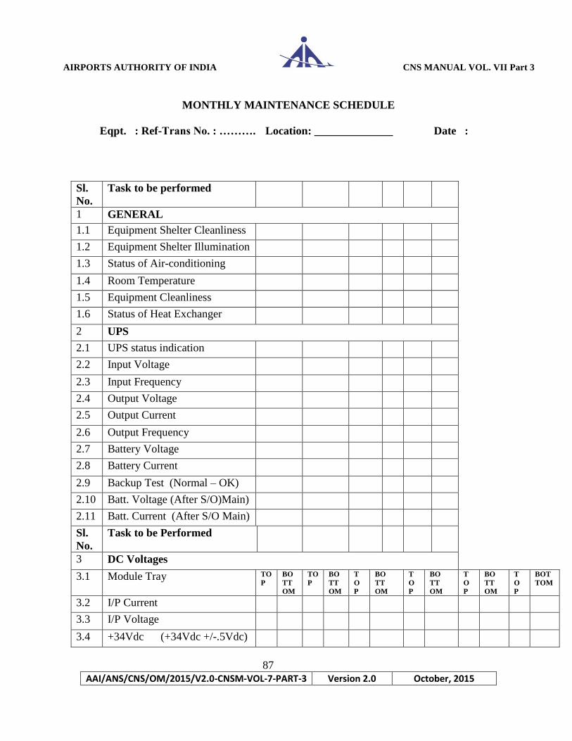
AIRPORTS AUTHORITY OF INDIA CNS MANUAL VOL. VII Part 3
87
AAI/ANS/CNS/OM/2015/V2.0-CNSM-VOL-7-PART-3 Version 2.0 October, 2015
MONTHLY MAINTENANCE SCHEDULE
Eqpt. : Ref-Trans No. : ………. Location: ______________ Date :
Sl.
No.
Task to be performed
1 GENERAL
1.1 Equipment Shelter Cleanliness
1.2 Equipment Shelter Illumination
1.3 Status of Air-conditioning
1.4 Room Temperature
1.5 Equipment Cleanliness
1.6 Status of Heat Exchanger
2 UPS
2.1 UPS status indication
2.2 Input Voltage
2.3 Input Frequency
2.4 Output Voltage
2.5 Output Current
2.6 Output Frequency
2.7 Battery Voltage
2.8 Battery Current
2.9 Backup Test (Normal – OK)
2.10 Batt. Voltage (After S/O)Main)
2.11 Batt. Current (After S/O Main)
Sl.
No.
Task to be Performed
3 DC Voltages
3.1 Module Tray TO
P
BO
TT
OM
TO
P
BO
TT
OM
T
O
P
BO
TT
OM
T
O
P
BO
TT
OM
T
O
P
BO
TT
OM
T
O
P
BOT
TOM
3.2 I/P Current
3.3 I/P Voltage
3.4 +34Vdc (+34Vdc +/-.5Vdc)

AIRPORTS AUTHORITY OF INDIA CNS MANUAL VOL. VII Part 3
88
AAI/ANS/CNS/OM/2015/V2.0-CNSM-VOL-7-PART-3 Version 2.0 October, 2015
RF Lightning Arrestor Maintenance
Visually inspect the components of the lightning arrestors for any physical damage.
1. Inspect antenna RF cables of all RUs and Reftrans and check for any loose connection.
2. Check the performance of UPS batteries by switching off the mains power supply and running
the equipment on UPS. Record the back up time of UPS batteries at each site.
(THIS MAINTENANCE SCHEDULE IS BASED ON RECOMMENDATIONS OF ICAO ANNEX 10, DGCA CAR’S
AND MANUFACTURER’S TECHNICAL MANUAL.)
3.5 +28Vdc (+28Vdc +/-.5Vdc)
3.6 +15Vdc (+15Vdc +/-.5Vdc)
3.7 +8Vdc (+8Vdc +/-.25Vdc)
3.8 +5Vdc (+5Vdc +/-.25Vdc)
3.9 -5Vdc (-5Vdc +/-.25Vdc)
3.10 RF O/P Power (dBm)
3.11 Error (All)
4 STATUS OF LRUs
4.1 Status of door switch
4.2 Status of Heat Exchanger
4.3 Status of 48V power supply
module
4.4 Status of A1 Module(Top)
4.5 Status of A2 Module (Bottom)
Sl.
No.
Task to be Performed
5 Remarks (if any)
6 Signature
with Design
Officer
Unit in
Charge
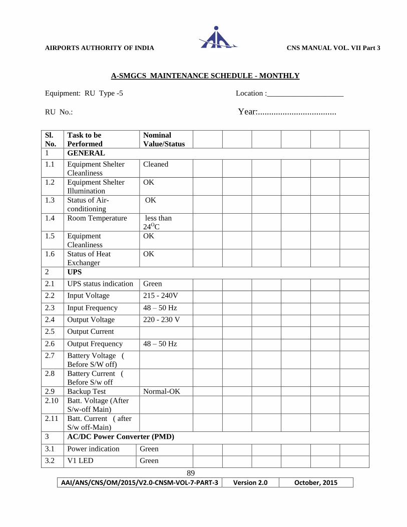
AIRPORTS AUTHORITY OF INDIA CNS MANUAL VOL. VII Part 3
89
AAI/ANS/CNS/OM/2015/V2.0-CNSM-VOL-7-PART-3 Version 2.0 October, 2015
A-SMGCS MAINTENANCE SCHEDULE - MONTHLY
Equipment: RU Type -5 Location :____________________
RU No.: Year:...................................
Sl.
No.
Task to be
Performed
Nominal
Value/Status
1 GENERAL
1.1 Equipment Shelter
Cleanliness
Cleaned
1.2 Equipment Shelter
Illumination
OK
1.3 Status of Air-
conditioning
OK
1.4 Room Temperature less than
24OC
1.5 Equipment
Cleanliness
OK
1.6 Status of Heat
Exchanger
OK
2 UPS
2.1 UPS status indication Green
2.2 Input Voltage 215 - 240V
2.3 Input Frequency 48 – 50 Hz
2.4 Output Voltage 220 - 230 V
2.5 Output Current
2.6 Output Frequency 48 – 50 Hz
2.7 Battery Voltage (
Before S/W off)
2.8 Battery Current (
Before S/w off
2.9 Backup Test Normal-OK
2.10 Batt. Voltage (After
S/w-off Main)
2.11 Batt. Current ( after
S/w off-Main)
3 AC/DC Power Converter (PMD)
3.1 Power indication Green
3.2 V1 LED Green
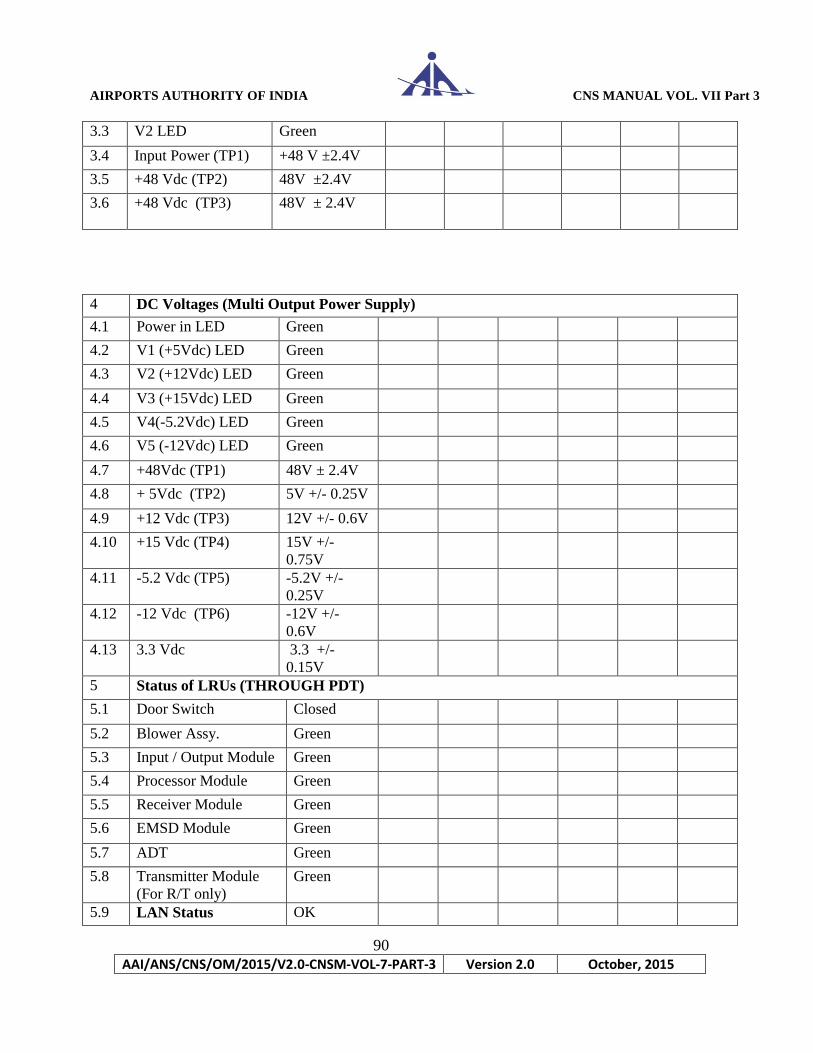
AIRPORTS AUTHORITY OF INDIA CNS MANUAL VOL. VII Part 3
90
AAI/ANS/CNS/OM/2015/V2.0-CNSM-VOL-7-PART-3 Version 2.0 October, 2015
3.3 V2 LED Green
3.4 Input Power (TP1) +48 V ±2.4V
3.5 +48 Vdc (TP2) 48V ±2.4V
3.6 +48 Vdc (TP3) 48V ± 2.4V
4 DC Voltages (Multi Output Power Supply)
4.1 Power in LED Green
4.2 V1 (+5Vdc) LED Green
4.3 V2 (+12Vdc) LED Green
4.4 V3 (+15Vdc) LED Green
4.5 V4(-5.2Vdc) LED Green
4.6 V5 (-12Vdc) LED Green
4.7 +48Vdc (TP1) 48V ± 2.4V
4.8 + 5Vdc (TP2) 5V +/- 0.25V
4.9 +12 Vdc (TP3) 12V +/- 0.6V
4.10 +15 Vdc (TP4) 15V +/-
0.75V
4.11 -5.2 Vdc (TP5) -5.2V +/-
0.25V
4.12 -12 Vdc (TP6) -12V +/-
0.6V
4.13 3.3 Vdc
3.3 +/-
0.15V
5 Status of LRUs (THROUGH PDT)
5.1 Door Switch Closed
5.2 Blower Assy. Green
5.3 Input / Output Module Green
5.4 Processor Module Green
5.5 Receiver Module Green
5.6 EMSD Module Green
5.7 ADT Green
5.8 Transmitter Module
(For R/T only)
Green
5.9 LAN Status OK

AIRPORTS AUTHORITY OF INDIA CNS MANUAL VOL. VII Part 3
91
AAI/ANS/CNS/OM/2015/V2.0-CNSM-VOL-7-PART-3 Version 2.0 October, 2015
RF Lightning Arrestor Maintenance
Visually inspect the components of the lightning arrestors for any physical damage.
1. Inspect antenna RF cables of all RUs and Reftrans and check for any loose connection.
2. Check the performance of UPS batteries by switching off the mains power supply and running the
equipment on UPS. Record the back up time of UPS batteries at each site.
(Sign of Duty Officer) (Sign of Unit Incharge)
(THIS MAINTENANCE SCHEDULE IS BASED ON RECOMMENDATIONS OF ICAO ANNEX 10, DGCA CAR’S
AND MANUFACTURER’S TECHNICAL MANUAL.)
5.9.1 Switch Status OK
5.9.2 Converter status OK
5.9.3 OFC Link OK
6.0 Check target
primitives
OK
6.1 Check interrogations
at R/T only
OK
7. RF Cable
Connection
OK
8 Date & Time
9 Signature of the
Executive with Desig
10 Signature of the Unit
in Charge with Desig
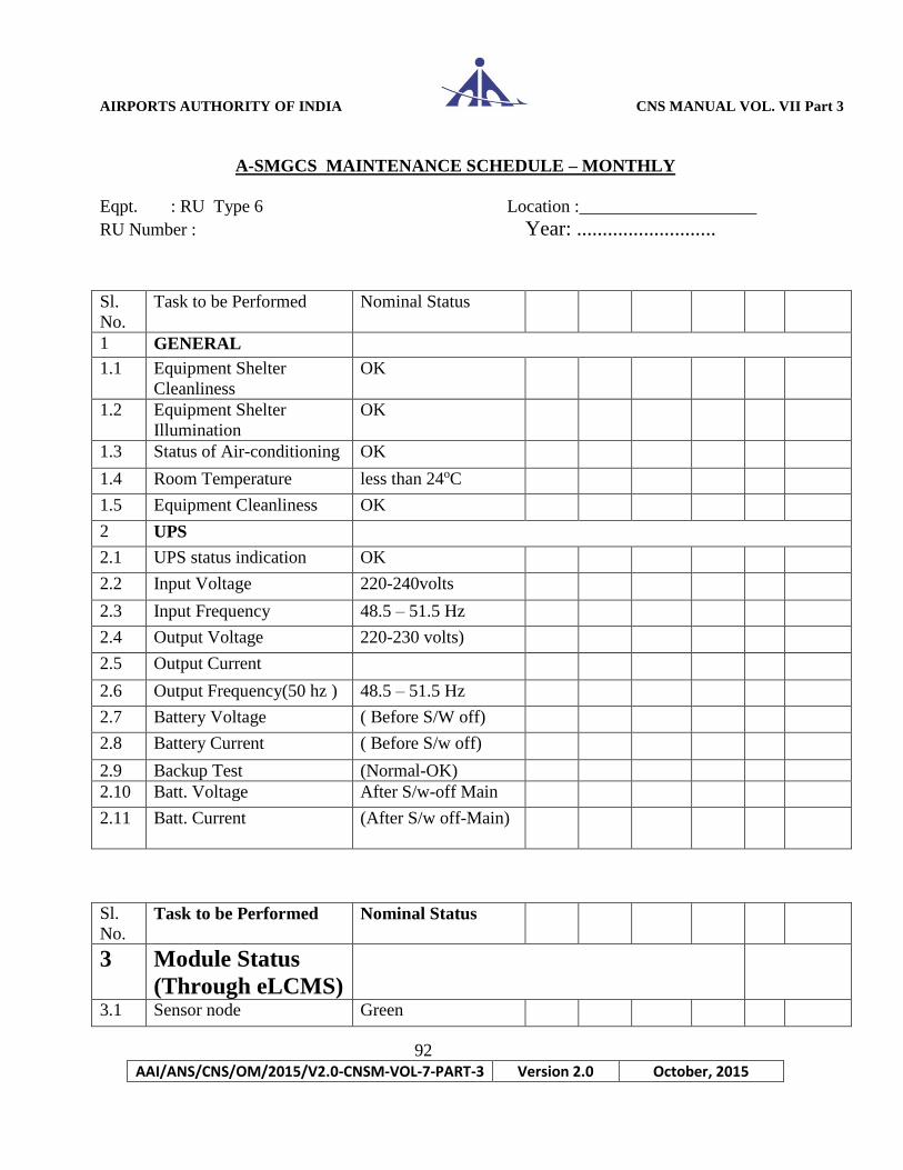
AIRPORTS AUTHORITY OF INDIA CNS MANUAL VOL. VII Part 3
92
AAI/ANS/CNS/OM/2015/V2.0-CNSM-VOL-7-PART-3 Version 2.0 October, 2015
A-SMGCS MAINTENANCE SCHEDULE – MONTHLY
Eqpt. : RU Type 6 Location :____________________
RU Number : Year: ...........................
Sl.
No.
Task to be Performed Nominal Status
1 GENERAL
1.1 Equipment Shelter
Cleanliness
OK
1.2 Equipment Shelter
Illumination
OK
1.3 Status of Air-conditioning OK
1.4 Room Temperature less than 24oC
1.5 Equipment Cleanliness OK
2 UPS
2.1 UPS status indication OK
2.2 Input Voltage 220-240volts
2.3 Input Frequency 48.5 – 51.5 Hz
2.4 Output Voltage 220-230 volts)
2.5 Output Current
2.6 Output Frequency(50 hz ) 48.5 – 51.5 Hz
2.7 Battery Voltage ( Before S/W off)
2.8 Battery Current ( Before S/w off)
2.9 Backup Test (Normal-OK)
2.10 Batt. Voltage After S/w-off Main
2.11 Batt. Current (After S/w off-Main)
Sl.
No. Task to be Performed Nominal Status
3 Module Status
(Through eLCMS)
3.1 Sensor node Green

AIRPORTS AUTHORITY OF INDIA CNS MANUAL VOL. VII Part 3
93
AAI/ANS/CNS/OM/2015/V2.0-CNSM-VOL-7-PART-3 Version 2.0 October, 2015
3.2 Communication node Green
3.3 Power Node Green
3.4 RF Antenna Green
3.5 GPS Status Not installed
4 Power Node
4.1 output power LED Green
4.2 DC Voltage 24V +/- 10%
4.3 Fan Blower OK
5 Sensor Node 5.1 Status LED Solid Green: Online
5.2 TP Comms LED Solid Green : Link
5.3
RF Receive LED Yellow : Mode
A/C (Flash per
Msg)
Green : Mode S
(Flash per msg)
5.4 RF Transmit (For
R/T only)
Green
5.5 GPS 1pps
Solid yellow: No
receiver
Sl.
No.
Task to be performed Nominal Value
6 Statistics (Through eLCMS)
6.1 Downlink statistics O.K.
6.2 Data to TP O.K.
6.3 Uplink Statistics
(For R/T Only)
O.K.
6.4 Data from TP O.K.
6.5 Hardware Statistics
6.5.1 Sensor node input
voltage
24V +/-10%
6.5.2 FPGA Temp < 52 OC

AIRPORTS AUTHORITY OF INDIA CNS MANUAL VOL. VII Part 3
94
AAI/ANS/CNS/OM/2015/V2.0-CNSM-VOL-7-PART-3 Version 2.0 October, 2015
Access the eLCMS
1. Connect the Ethernet cable to LMI port on the Sensor Node and the Ethernet
port on the Laptop.
2. Verify DHCP setting on the Laptop
a) In the Internet Portocol (TCP/IP) properties windows, Select obtain an IP
address automatically.
3. Open Internet Explorer. In the address box enter the following URL address
http://192.168.145.126/html/index.html
4. Opening screen of eLCMS application appears.
RF Lightning Arrestor Maintenance: Visually inspect the components of the lightning arrestors for any physical damage.
1. Inspect antenna RF cables of all RUs and Reftrans and check for any loose
connection.
2. Check the performance of UPS batteries by switching off the mains power
supply and running the equipment on UPS. Record the back up time of UPS
batteries at each site.
(Sign of Duty Officer) (Sign of Unit Incharge)
(THIS MAINTENANCE SCHEDULE IS BASED ON RECOMMENDATIONS OF ICAO ANNEX 10, DGCA CAR’S
AND MANUFACTURER’S TECHNICAL MANUAL.)
6.5.3 RF Tx Board Temp
7 LAN Status
7.1 Switch Status O.K.
7.2 Converter status O.K.
7.3 OFC Link O.K.
8 Date & Time
9 Signature of the
Executive with
Designation:
10 Signature of the Unit in-
Charge with Desig
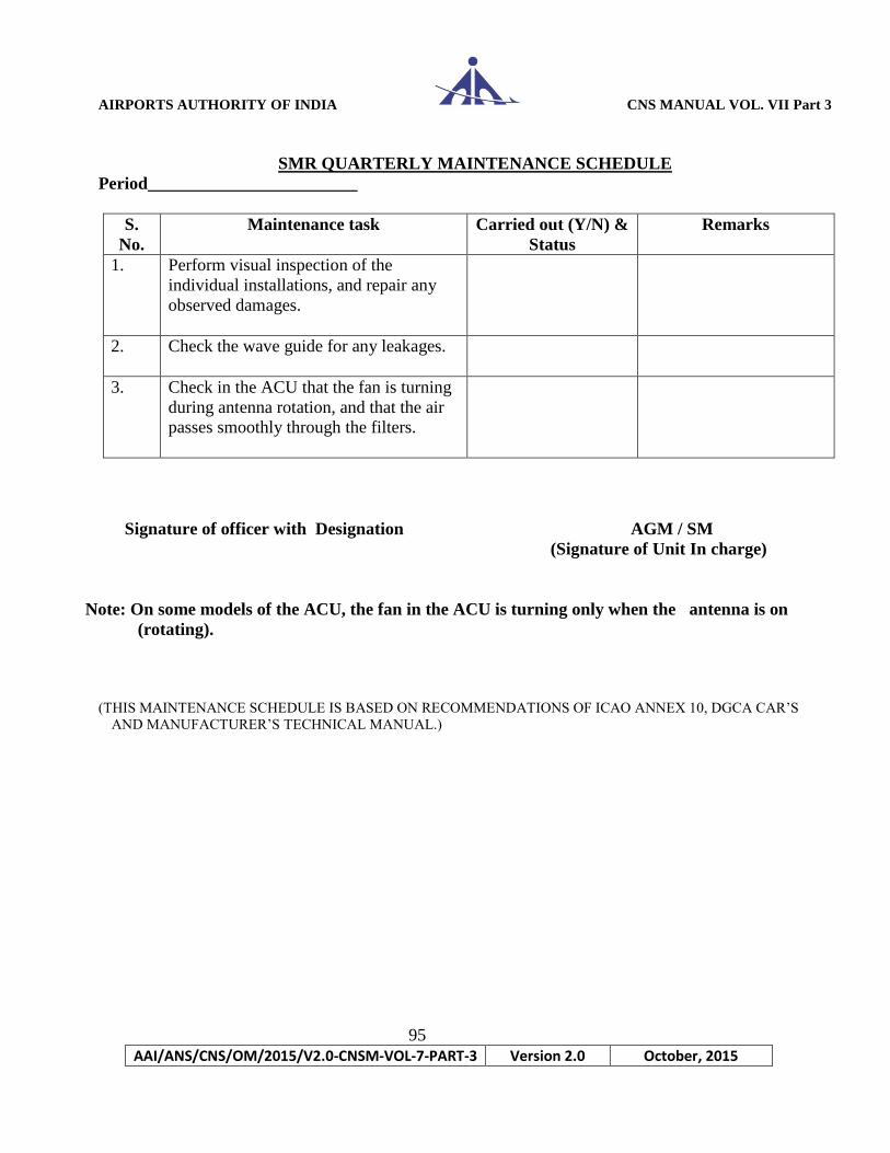
AIRPORTS AUTHORITY OF INDIA CNS MANUAL VOL. VII Part 3
95
AAI/ANS/CNS/OM/2015/V2.0-CNSM-VOL-7-PART-3 Version 2.0 October, 2015
SMR QUARTERLY MAINTENANCE SCHEDULE
Period________________________
S.
No.
Maintenance task Carried out (Y/N) &
Status
Remarks
1. Perform visual inspection of the
individual installations, and repair any
observed damages.
2. Check the wave guide for any leakages.
3. Check in the ACU that the fan is turning
during antenna rotation, and that the air
passes smoothly through the filters.
Signature of officer with Designation AGM / SM
(Signature of Unit In charge)
Note: On some models of the ACU, the fan in the ACU is turning only when the antenna is on
(rotating).
(THIS MAINTENANCE SCHEDULE IS BASED ON RECOMMENDATIONS OF ICAO ANNEX 10, DGCA CAR’S
AND MANUFACTURER’S TECHNICAL MANUAL.)
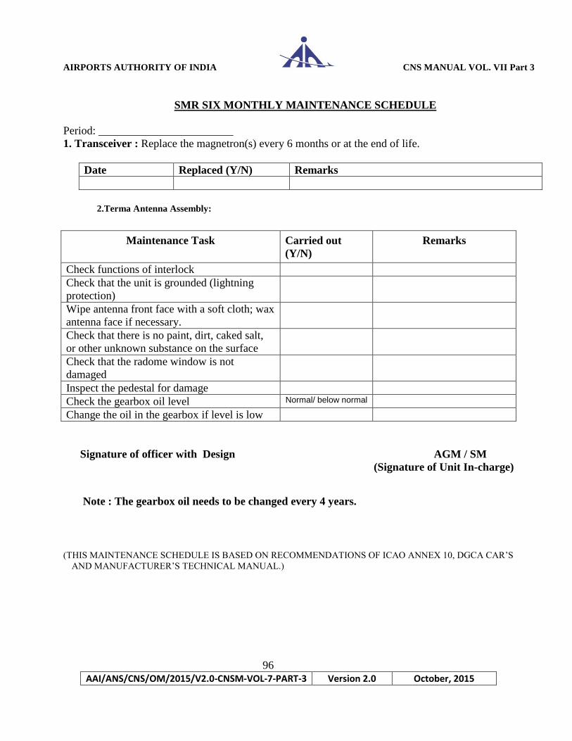
AIRPORTS AUTHORITY OF INDIA CNS MANUAL VOL. VII Part 3
96
AAI/ANS/CNS/OM/2015/V2.0-CNSM-VOL-7-PART-3 Version 2.0 October, 2015
SMR SIX MONTHLY MAINTENANCE SCHEDULE
Period: ________________________
1. Transceiver : Replace the magnetron(s) every 6 months or at the end of life.
Date Replaced (Y/N) Remarks
2.Terma Antenna Assembly:
Signature of officer with Design AGM / SM
(Signature of Unit In-charge)
Note : The gearbox oil needs to be changed every 4 years.
(THIS MAINTENANCE SCHEDULE IS BASED ON RECOMMENDATIONS OF ICAO ANNEX 10, DGCA CAR’S
AND MANUFACTURER’S TECHNICAL MANUAL.)
Maintenance Task Carried out
(Y/N)
Remarks
Check functions of interlock
Check that the unit is grounded (lightning
protection)
Wipe antenna front face with a soft cloth; wax
antenna face if necessary.
Check that there is no paint, dirt, caked salt,
or other unknown substance on the surface
Check that the radome window is not
damaged
Inspect the pedestal for damage
Check the gearbox oil level Normal/ below normal
Change the oil in the gearbox if level is low
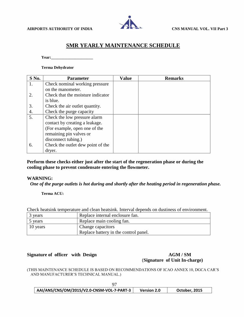
AIRPORTS AUTHORITY OF INDIA CNS MANUAL VOL. VII Part 3
97
AAI/ANS/CNS/OM/2015/V2.0-CNSM-VOL-7-PART-3 Version 2.0 October, 2015
SMR YEARLY MAINTENANCE SCHEDULE
Year:_____________________
Terma Dehydrator
S No. Parameter Value Remarks
1. Check nominal working pressure
on the manometer.
2. Check that the moisture indicator
is blue.
3. Check the air outlet quantity.
4. Check the purge capacity
5. Check the low pressure alarm
contact by creating a leakage.
(For example, open one of the
remaining pin valves or
disconnect tubing.)
6. Check the outlet dew point of the
dryer.
Perform these checks either just after the start of the regeneration phase or during the
cooling phase to prevent condensate entering the flowmeter.
WARNING:
One of the purge outlets is hot during and shortly after the heating period in regeneration phase.
Terma ACU:
Check heatsink temperature and clean heatsink. Interval depends on dustiness of environment.
3 years Replace internal enclosure fan.
5 years Replace main cooling fan.
10 years Change capacitors
Replace battery in the control panel.
Signature of officer with Design AGM / SM
(Signature of Unit In-charge)
(THIS MAINTENANCE SCHEDULE IS BASED ON RECOMMENDATIONS OF ICAO ANNEX 10, DGCA CAR’S
AND MANUFACTURER’S TECHNICAL MANUAL.)
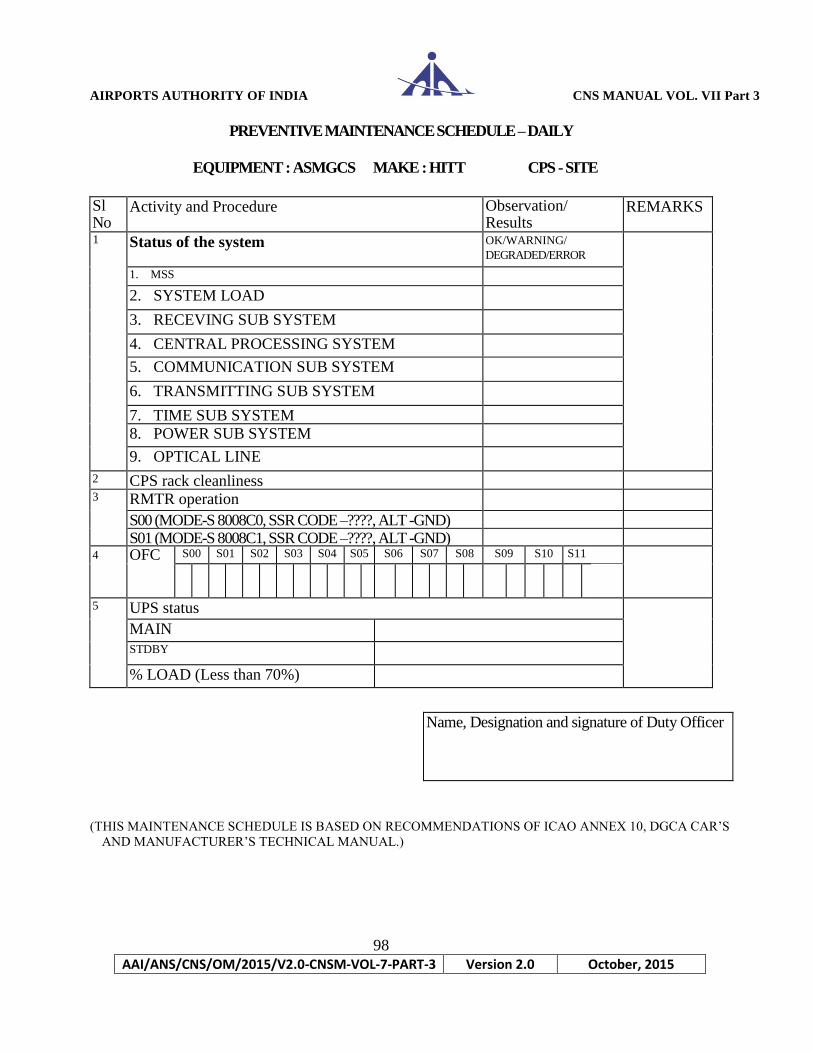
AIRPORTS AUTHORITY OF INDIA CNS MANUAL VOL. VII Part 3
98
AAI/ANS/CNS/OM/2015/V2.0-CNSM-VOL-7-PART-3 Version 2.0 October, 2015
PREVENTIVE MAINTENANCE SCHEDULE – DAILY
EQUIPMENT : ASMGCS MAKE : HITT CPS - SITE
Sl No
Activity and Procedure Observation/ Results
REMARKS
1 Status of the system OK/WARNING/
DEGRADED/ERROR
1. MSS
2. SYSTEM LOAD
3. RECEVING SUB SYSTEM
4. CENTRAL PROCESSING SYSTEM
5. COMMUNICATION SUB SYSTEM
6. TRANSMITTING SUB SYSTEM
7. TIME SUB SYSTEM
8. POWER SUB SYSTEM
9. OPTICAL LINE
2 CPS rack cleanliness 3 RMTR operation
S00 (MODE-S 8008C0, SSR CODE –????, ALT -GND)
S01 (MODE-S 8008C1, SSR CODE –????, ALT -GND) 4 OFC
Status A & B
S00 S01 S02 S03 S04 S05 S06 S07 S08 S09 S10 S11
5 UPS status
MAIN
STDBY
% LOAD (Less than 70%)
(THIS MAINTENANCE SCHEDULE IS BASED ON RECOMMENDATIONS OF ICAO ANNEX 10, DGCA CAR’S
AND MANUFACTURER’S TECHNICAL MANUAL.)
Name, Designation and signature of Duty Officer

AIRPORTS AUTHORITY OF INDIA CNS MANUAL VOL. VII Part 3
99
AAI/ANS/CNS/OM/2015/V2.0-CNSM-VOL-7-PART-3 Version 2.0 October, 2015
PREVENTIVE MAINTENANCE SCHEDULE - WEEKLY
EQUIPMENT : ASMGCS MAKE : HITT CPS - SITE
UPS- 1 batteries check (ODD weeks) Date:
Total DC voltage Before load test After load test
Individual battery voltage
Before load test After load test 1
2
3
4
5
6
7
8
9
10
11
12
13
14
15
16
17
18
19
20
UPS- 1 batteries check (EVEN weeks) Date:
Total DC voltage
Before load test After load test
Individual battery voltage
Before load test After load test
1
2
3
4
5
6
7
8
9
10
11
12
13
14
15
16
17
18
19
20
Remarks Remarks
Name, Designation and signature Name, Designation and signature
of Duty Officer of Duty Officer
(THIS MAINTENANCE SCHEDULE IS BASED ON RECOMMENDATIONS OF ICAO ANNEX 10, DGCA
CAR’S AND MANUFACTURER’S TECHNICAL MANUAL.)

AIRPORTS AUTHORITY OF INDIA CNS MANUAL VOL. VII Part 3
100
AAI/ANS/CNS/OM/2015/V2.0-CNSM-VOL-7-PART-3 Version 2.0 October, 2015
PREVENTIVE MAINTENANCE SCHEDULE – SIX MONTHLY
EQUIPMENT : ASMGCS MAKE : HITT CPS - SITE
2 Check the status of communication among the system parts of MSS at Management System.
(i) LAN card diagnostics:
(ii) TCP/IP communication diagnostics
Signature of DGM Name, Designation and signature of Duty Officer
Asst GM/SM
(THIS MAINTENANCE SCHEDULE IS BASED ON RECOMMENDATIONS OF ICAO ANNEX 10, DGCA
CAR’S AND MANUFACTURER’S TECHNICAL MANUAL.)
S.No. Activity
1 Check the logs with the long term statistic information about the system alarms at
Management System log archives.
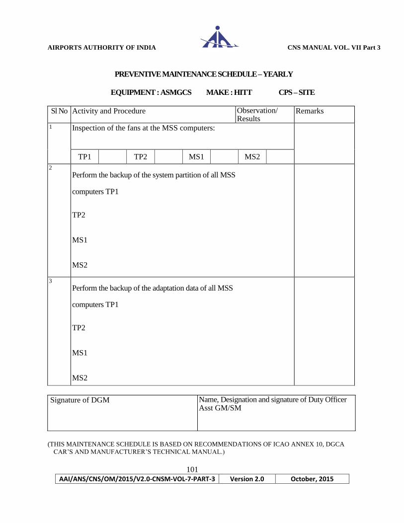
AIRPORTS AUTHORITY OF INDIA CNS MANUAL VOL. VII Part 3
101
AAI/ANS/CNS/OM/2015/V2.0-CNSM-VOL-7-PART-3 Version 2.0 October, 2015
PREVENTIVE MAINTENANCE SCHEDULE – YEARLY
EQUIPMENT : ASMGCS MAKE : HITT CPS – SITE
Sl No Activity and Procedure Observation/ Results
Remarks
1 Inspection of the fans at the MSS computers:
TP1 TP2 MS1 MS2
2 Perform the backup of the system partition of all MSS
computers TP1
TP2
MS1
MS2
3 Perform the backup of the adaptation data of all MSS
computers TP1
TP2
MS1
MS2
Signature of DGM Name, Designation and signature of Duty Officer Asst GM/SM
(THIS MAINTENANCE SCHEDULE IS BASED ON RECOMMENDATIONS OF ICAO ANNEX 10, DGCA
CAR’S AND MANUFACTURER’S TECHNICAL MANUAL.)

AIRPORTS AUTHORITY OF INDIA CNS MANUAL VOL. VII Part 3
102
AAI/ANS/CNS/OM/2015/V2.0-CNSM-VOL-7-PART-3 Version 2.0 October, 2015
PREVENTIVE MAINTENANCE SCHEDULE – DAILY
EQUIPMENT : ASMGCS MAKE : HITT CMS – SITE
Sl No Activity OK/Degraded /Warning/Error
Remarks
Check system status using CMS CMSP01
CMSP02
CTP01
CTP02
DP01
DP02
DP03
IP01
IP02
RDP01
RDP02
RDP03
RDP04
RRP01
RRP02
(THIS MAINTENANCE SCHEDULE IS BASED ON RECOMMENDATIONS OF ICAO ANNEX 10, DGCA
CAR’S AND MANUFACTURER’S TECHNICAL MANUAL.)
Name, Designation and signature of Duty Officer

AIRPORTS AUTHORITY OF INDIA CNS MANUAL VOL. VII Part 3
103
AAI/ANS/CNS/OM/2015/V2.0-CNSM-VOL-7-PART-3 Version 2.0 October, 2015
PREVENTIVE MAINTENANCE SCHEDULE – WEELY
EQUIPMENT : ASMGCS MAKE : HITT CMS – SITE
Sl No 1
2
3
4
5
Activity Observation/
Results
Remarks
1 Replace ARCHIT tape Replaced/ not replaced
2
Check report files
3 Check external interface with Approach radar
4
Check Flight plan interface
5 Check time synchronization
Name, Designation and signature of Duty Officer
(THIS MAINTENANCE SCHEDULE IS BASED ON RECOMMENDATIONS OF ICAO ANNEX 10, DGCA
CAR’S AND MANUFACTURER’S TECHNICAL MANUAL.)

AIRPORTS AUTHORITY OF INDIA CNS MANUAL VOL. VII Part 3
104
AAI/ANS/CNS/OM/2015/V2.0-CNSM-VOL-7-PART-3 Version 2.0 October, 2015
PREVENTIVE MAINTENANCE SCHEDULE - MONTHLY
EQUIPMENT : ASMGCS MAKE : HITT CMS – SITE
S. No Activity Observation/ Results Remarks
M1 Check (and adapt) Video Alignment of the SMR video
M2 Check Linux processes
M3 Check computer load
M4 Check memory usage
M5 Check disk space

AIRPORTS AUTHORITY OF INDIA CNS MANUAL VOL. VII Part 3
105
AAI/ANS/CNS/OM/2015/V2.0-CNSM-VOL-7-PART-3 Version 2.0 October, 2015
M6 Check redundancy
M7 Check backup of changes
M8 Check archit tape
M9 Check on any core files
Name, Designation and signature of Duty Officer
(THIS MAINTENANCE SCHEDULE IS BASED ON RECOMMENDATIONS OF ICAO ANNEX 10, DGCA
CAR’S AND MANUFACTURER’S TECHNICAL MANUAL.)

AIRPORTS AUTHORITY OF INDIA CNS MANUAL VOL. VII Part 3
106
AAI/ANS/CNS/OM/2015/V2.0-CNSM-VOL-7-PART-3 Version 2.0 October, 2015
PREVENTIVE MAINTENANCE SCHEDULE - SIX MONTHLY
EQUIPMENT : ASMGCS MAKE : HITT MLATs
Sl
No
Activity and Procedure Observation/
Results
Remarks
1) Remove foreign elements that could deteriorate the efficiency of the electronic modules cooling
ability, etc.
S00
S01
S02
S03
S04
S05
S06
S07
S08
S09
S10
S11
S12
Remarks
Signature of DGM Name, Designation and signature of Duty Officer Asst GM/SM
(THIS MAINTENANCE SCHEDULE IS BASED ON RECOMMENDATIONS OF ICAO ANNEX 10, DGCA
CAR’S AND MANUFACTURER’S TECHNICAL MANUAL.)

AIRPORTS AUTHORITY OF INDIA CNS MANUAL VOL. VII Part 3
107
AAI/ANS/CNS/OM/2015/V2.0-CNSM-VOL-7-PART-3 Version 2.0 October, 2015
PREVENTIVE MAINTENANCE SCHEDULE - SIX MONTHLY
EQUIPMENT : ASMGCS MAKE : HITT MLATs
2 Visual check of the antenna and the antenna feeder:
S00
S01
S02
S03
S04
S05
S06
S07
S08
S09
S10
S11
S12
Remarks
Signature of DGM Name, Designation and signature of Duty Officer Asst GM/SM
(THIS MAINTENANCE SCHEDULE IS BASED ON RECOMMENDATIONS OF ICAO ANNEX 10, DGCA
CAR’S AND MANUFACTURER’S TECHNICAL MANUAL.)
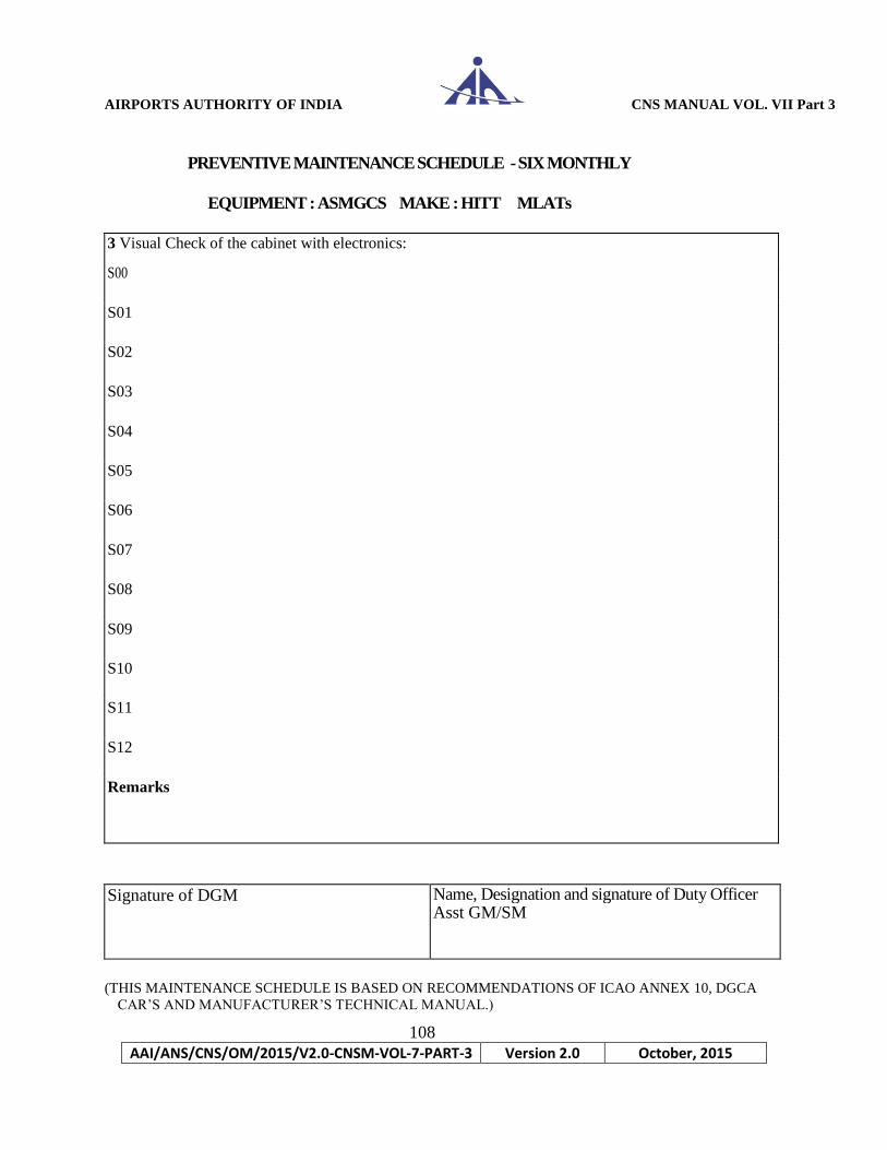
AIRPORTS AUTHORITY OF INDIA CNS MANUAL VOL. VII Part 3
108
AAI/ANS/CNS/OM/2015/V2.0-CNSM-VOL-7-PART-3 Version 2.0 October, 2015
PREVENTIVE MAINTENANCE SCHEDULE - SIX MONTHLY
EQUIPMENT : ASMGCS MAKE : HITT MLATs
3 Visual Check of the cabinet with electronics:
S00
S01
S02
S03
S04
S05
S06
S07
S08
S09
S10
S11
S12
Remarks
Signature of DGM Name, Designation and signature of Duty Officer Asst GM/SM
(THIS MAINTENANCE SCHEDULE IS BASED ON RECOMMENDATIONS OF ICAO ANNEX 10, DGCA
CAR’S AND MANUFACTURER’S TECHNICAL MANUAL.)

AIRPORTS AUTHORITY OF INDIA CNS MANUAL VOL. VII Part 3
109
AAI/ANS/CNS/OM/2015/V2.0-CNSM-VOL-7-PART-3 Version 2.0 October, 2015
PREVENTIVE MAINTENANCE SCHEDULE - SIX MONTHLY
EQUIPMENT : ASMGCS MAKE : HITT MLATs
4 Detection of faults and anomalies:
S00
S01
S02
S03
S04
S05
S06
S07
S08
S09
S10
S11
S12
Remarks
Signature of DGM
Name, Designation and signature of Duty Officer Asst GM/SM
(THIS MAINTENANCE SCHEDULE IS BASED ON RECOMMENDATIONS OF ICAO ANNEX 10, DGCA
CAR’S AND MANUFACTURER’S TECHNICAL MANUAL.)
AIRPORTS AUTHORITY OF INDIA CNS MANUAL VOL. VII Part 3
110
AAI/ANS/CNS/OM/2015/V2.0-CNSM-VOL-7-PART-3 Version 2.0 October, 2015
PREVENTIVE MAINTENANCE SCHEDULE - SIX MONTHLY
EQUIPMENT : ASMGCS MAKE : HITT MLATs
5. MLAT mast inspection:
S01
Remarks
Signature of DGM Name, Designation and signature of Duty Officer Asst GM/SM
(THIS MAINTENANCE SCHEDULE IS BASED ON RECOMMENDATIONS OF ICAO ANNEX 10, DGCA
CAR’S AND MANUFACTURER’S TECHNICAL MANUAL.)

AIRPORTS AUTHORITY OF INDIA CNS MANUAL VOL. VII Part 3
111
AAI/ANS/CNS/OM/2015/V2.0-CNSM-VOL-7-PART-3 Version 2.0 October, 2015
PREVENTIVE MAINTENANCE SCHEDULE - DAILY
EQUIPMENT : ASMGCS MAKE : HITT SMR – SITE
Sl No Activity Observation/ Results
Remarks
1 Status of Air-conditioning in UPS HUT
2 Equipment room cleanliness UPS -HUT
3 Temperature in UPS HUT
4 Status of Air-conditioning in Equipment HUT
5 Equipment room cleanliness Equipment HUT
6 Temperature in Equipment HUT
7 Check BITE measurement and Modules errors
8 UPS status UPS MAIN
UPS STANDBY
% LOAD (Less than 70%)
(THIS MAINTENANCE SCHEDULE IS BASED ON RECOMMENDATIONS OF ICAO ANNEX 10, DGCA
CAR’S AND MANUFACTURER’S TECHNICAL MANUAL.)
Name, Designation and signature of Duty Officer

AIRPORTS AUTHORITY OF INDIA CNS MANUAL VOL. VII Part 3
112
AAI/ANS/CNS/OM/2015/V2.0-CNSM-VOL-7-PART-3 Version 2.0 October, 2015
PREVENTIVE MAINTENANCE SCHEDULE - WEEKLY
EQUIPMENT : ASMGCS MAKE : HITT SMR – SITE
UPS- 1 batteries check (ODD weeks) Date:
Total DC voltage
Before load test Before load test
Individual battery voltage
Before load test Before load test 1
2 3
4 5
6 7
8 9
10
2 3 4 5 6 7 8 9 10
2 3
4
5
6
7
8
9
10
Active RXTX change over
Currently
active RXTX 1
/ RXTX 2
Changeover to
RXTX 1 / RXTX
2
Air conditioner change over
A/C change over in UPS HUT
A/C change over in SMR HUT
REMARKS :
UPS- 1 batteries check (ODD weeks) Date:
Total DC voltage
Before load test Before load test
Individual battery voltage
Before load test Before load test
1
2 3 4
5 6 7
8 9
10
2 3 4 5 6 7 8 9 10
2 3
4
5
6
7
8 9
10
Active RXTX change over
Currently
active RXTX 1
/ RXTX 2
Changeover to
RXTX 1 / RXTX
2
Air conditioner change over
A/C change over in UPS HUT
A/C change over in SMR HUT
REMARKS :
Name, Designation & signature
Of Duty Officer
(THIS MAINTENANCE SCHEDULE IS BASED ON RECOMMENDATIONS OF ICAO ANNEX 10, DGCA
CAR’S AND MANUFACTURER’S TECHNICAL MANUAL.)
AIRPORTS AUTHORITY OF INDIA CNS MANUAL VOL. VII Part 3
113
AAI/ANS/CNS/OM/2015/V2.0-CNSM-VOL-7-PART-3 Version 2.0 October, 2015
PREVENTIVE MAINTENANCE SCHEDULE - MONTHLY
EQUIPMENT : ASMGCS MAKE : HITT SMR – SITE
Azimuth check and alignment
Name, Designation and signature of Duty Officer
(THIS MAINTENANCE SCHEDULE IS BASED ON RECOMMENDATIONS OF ICAO ANNEX 10, DGCA
CAR’S AND MANUFACTURER’S TECHNICAL MANUAL.)
AIRPORTS AUTHORITY OF INDIA CNS MANUAL VOL. VII Part 3
114
AAI/ANS/CNS/OM/2015/V2.0-CNSM-VOL-7-PART-3 Version 2.0 October, 2015
PREVENTIVE MAINTENANCE SCHEDULE - QUARTERLY
EQUIPMENT : ASMGCS MAKE : HITT SMR – SITE
1
Check Static Dehydrator
2 Clean/replace filters
3
Clean all surfaces
Remarks
Name, Designation and signature Name, Designation and signature of
of Duty Officer of Duty Officer
(THIS MAINTENANCE SCHEDULE IS BASED ON RECOMMENDATIONS OF ICAO ANNEX 10, DGCA
CAR’S AND MANUFACTURER’S TECHNICAL MANUAL.)
AIRPORTS AUTHORITY OF INDIA CNS MANUAL VOL. VII Part 3
115
AAI/ANS/CNS/OM/2015/V2.0-CNSM-VOL-7-PART-3 Version 2.0 October, 2015
PREVENTIVE MAINTENANCE SCHEDULE - SIX-MONTHLY
EQUIPMENT : ASMGCS MAKE : HITT SMR – SITE
Magnetron replacement check
1. hours of transmisS10n of magnetron :
2. Age of magnetron :
3. Forward Power :
4. Date of replacement of magnetron :
Remarks
Name, Designation and signature of Duty Officer
(THIS MAINTENANCE SCHEDULE IS BASED ON RECOMMENDATIONS OF ICAO ANNEX 10, DGCA
CAR’S AND MANUFACTURER’S TECHNICAL MANUAL.)

Airports Authority of India CNS Manual Vol. VII Part 3
116
AAI/ANS/CNS/OM/2015/V2.0-CNSM-VOL-7-PART-3 Version 2.0 October, 2015
SURFACE MOVEMENT RADAR BITE MEASUREMENT REGISTER(SMR1)
MEA
SUR
MEN
T TYPE
A.MOTHER BOARD AND POWER SUPPLY
DATES
-15V
M1
M2
-5V M1
M2
+28V M1
M2
+48 M1
M2
+5V ENCODER
M1 M2
+5V PILO
T
M1
M2
+5V M1
M2
+15V M1
M2 ANTENN
A RPM
M1
M2
MAINS ON TIME M1
M2
B. MODULATOR
MAG PEAK CURRENT
M1
M2
MOD MEAN CURRENT
M1
M2
MOD HIGH VOLTAGE
M1 M2
TEMPERATURE SWITCH
M1 M2
TEMPERATURE CONV
M1
M2
FILAMENT ON TIME
M1
M2
TX ON TIME M1 M2
SIGNATURE
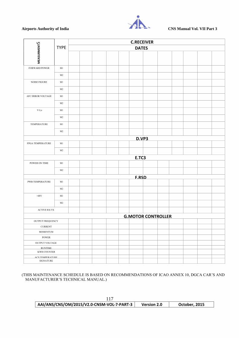
Airports Authority of India CNS Manual Vol. VII Part 3
117
AAI/ANS/CNS/OM/2015/V2.0-CNSM-VOL-7-PART-3 Version 2.0 October, 2015
MEA
SUR
MEN
TS
TYPE C.RECEIVER
DATES
FORWARD POWER M1
M2
NOISE FIGURE M1
M2
AFC ERROR VOLTAGE M1
M2
V-Lo M1
M2
TEMPERATURE M1
M2
D.VP3 FPGA TEMPERATURE M1
M2
E.TC3 POWER ON TIME M1
M2
F.RSD PWB TEMPERATURE M1
M2
+48V M1
M2
ACTIVE RX/TX
G.MOTOR CONTROLLER OUTPUT FREQUENCY
CURRENT MOMENTUM
POWER OUTPUT VOLTAGE
RUNTIME KWH COUNTER
ACS TEMPERATURE SIGNATURE
(THIS MAINTENANCE SCHEDULE IS BASED ON RECOMMENDATIONS OF ICAO ANNEX 10, DGCA CAR’S AND
MANUFACTURER’S TECHNICAL MANUAL.)

Airports Authority of India CNS Manual Vol. VII Part 3
118
AAI/ANS/CNS/OM/2015/V2.0-CNSM-VOL-7-PART-3 Version 2.0 October, 2015
Parameters UPS1 UPS2
O/P Voltage
O/P Frequency
Runtime
Battery Voltage
Power (in %)
PREVENTIVE MAINTENANCE SCHEDULE – DAILY ASMGCS/SMR-1
Location: ATC TOWER Month: Year: Make: SELEX
FREQUENCY:
Operational status: Mode (TxRx A/B/A+B)
Operational Status: Radiation ( on/off )
Role of Extractor Operative TxRx Interface A/B
Operative Encoder
A/B A B
SMR STATUS: Status Ok/Not Ok Type of fail
Message
Action Taken Remarks
Link Status
Extr A Status
Extr B Status
TxRx A Status
TxRx B Status
Antenna Status
UPS Status
TX RX Maintenance : UPS Status:
Parameters TXRX A TXRX B
TXRX Temp.
MG Peak Current Level
Main Bang Level
Rx Noise Level
Forward Power Level
Task Equipment Room
UPS Room
Temperature
Cleanliness
Signature of Unit in Charge Signature of Duty Officer
Name & Designation: Name & Designation:
(THIS MAINTENANCE SCHEDULE IS BASED ON RECOMMENDATIONS OF ICAO ANNEX 10, DGCA CAR’S AND
MANUFACTURER’S TECHNICAL MANUAL.)
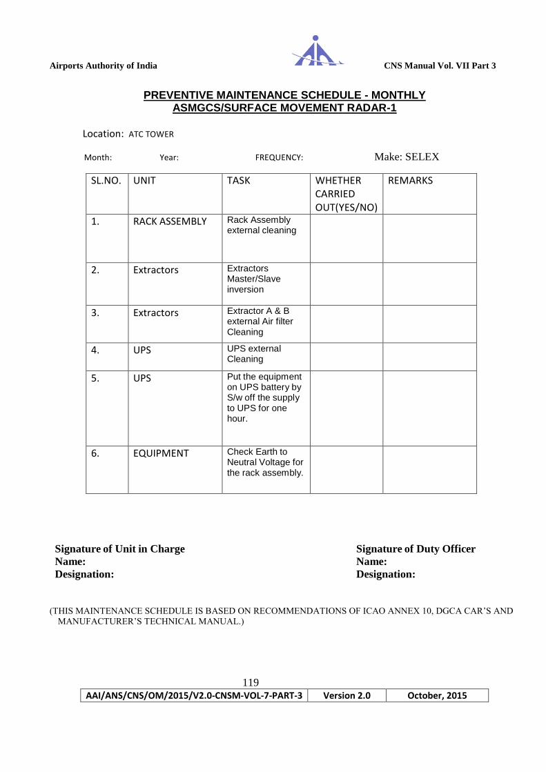
Airports Authority of India CNS Manual Vol. VII Part 3
119
AAI/ANS/CNS/OM/2015/V2.0-CNSM-VOL-7-PART-3 Version 2.0 October, 2015
PREVENTIVE MAINTENANCE SCHEDULE - MONTHLY ASMGCS/SURFACE MOVEMENT RADAR-1
Location: ATC TOWER
Month: Year: FREQUENCY: Make: SELEX
SL.NO. UNIT TASK WHETHER
CARRIED OUT(YES/NO)
REMARKS
1. RACK ASSEMBLY Rack Assembly external cleaning
2. Extractors Extractors Master/Slave inversion
3. Extractors Extractor A & B external Air filter Cleaning
4. UPS UPS external Cleaning
5. UPS Put the equipment on UPS battery by S/w off the supply to UPS for one hour.
6. EQUIPMENT Check Earth to Neutral Voltage for the rack assembly.
Signature of Unit in Charge Signature of Duty Officer
Name: Name:
Designation: Designation:
(THIS MAINTENANCE SCHEDULE IS BASED ON RECOMMENDATIONS OF ICAO ANNEX 10, DGCA CAR’S AND
MANUFACTURER’S TECHNICAL MANUAL.)
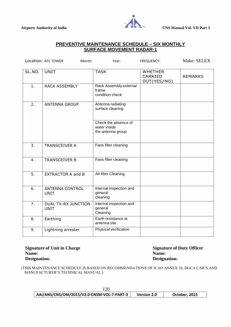
Airports Authority of India CNS Manual Vol. VII Part 3
120
AAI/ANS/CNS/OM/2015/V2.0-CNSM-VOL-7-PART-3 Version 2.0 October, 2015
PREVENTIVE MAINTENANCE SCHEDULE – SIX MONTHLY SURFACE MOVEMENT RADAR-1
Location: ATC TOWER Month: Year: FREQUENCY: Make: SELEX
SL.NO. UNIT TASK WHETHER
CARRIED
OUT(YES/NO)
REMARKS
1. RACK ASSEMBLY Rack Assembly external frame condition check
2. ANTENNA GROUP Antenna radiating surface cleaning
Check the absence of water inside the antenna group
3. TRANSCEIVER A Fans filter cleaning
4. TRANSCEIVER B Fans filter cleaning
5. EXTRACTOR A and B Air filter Cleaning
6. ANTENNA CONTROL
UNIT Internal inspection and general cleaning
7. DUAL TX-RX JUNCTION UNIT
Internal inspection and general Cleaning
8. Earthing Earth resistance at antenna site
9. Lightning arrester Physical verification
Signature of Unit in Charge Signature of Duty Officer
Name: Name:
Designation: Designation:
(THIS MAINTENANCE SCHEDULE IS BASED ON RECOMMENDATIONS OF ICAO ANNEX 10, DGCA CAR’S AND
MANUFACTURER’S TECHNICAL MANUAL.)

Airports Authority of India CNS Manual Vol. VII Part 3
121
AAI/ANS/CNS/OM/2015/V2.0-CNSM-VOL-7-PART-3 Version 2.0 October, 2015
PREVENTIVE MAINTENANCE SCHEDULE - YEARLY ASMGCS/SURFACE MOVEMENT RADAR-1
Location: ATC TOWER Month: Year: FREQUENCY: Make: SELEX
SL.NO. UNIT TASK WHETHER CARRIED OUT(YES/NO)
REMARKS
1. Rack Assembly Rack Assembly cables and connectors condition check
2. Antenna Group Ground connection check
Motor belt tightening check
Fastening screws cleaning
3. Transceiver A and B
Internal inspection and general cleaning
4. System Cables and connectors check
Flexible waveguide check
Signature of Unit in Charge Signature of Duty Officer
Name: Name:
Designation: Designation:
(THIS MAINTENANCE SCHEDULE IS BASED ON RECOMMENDATIONS OF ICAO ANNEX 10, DGCA CAR’S AND
MANUFACTURER’S TECHNICAL MANUAL.)

Airports Authority of India CNS Manual Vol. VII Part 3
122
AAI/ANS/CNS/OM/2015/V2.0-CNSM-VOL-7-PART-3 Version 2.0 October, 2015
Parameters UPS1 UPS2
O/P Voltage
O/P Frequency
Runtime
Battery Voltage
Power (in %)
DAILY PREVENTIVE MAINTENANCE SURFACE MOVEMENT RADAR-2
Location FREQUENCY Date ARFF BUILDING 9490/9375 MHz
Operational status: Mode (TxRx A/B/A+B)
Operational Status-- Radiation ( on/off )
Role of Extractor Operative TxRx Interface A/B
Opeartive Encoder
A/B A B
SMR STATUS: Status Ok/Not Ok Type of fail
Message
Action Taken Remarks
Link Status
Extr A Status
Extr B Status
TxRx A Status
TxRx B Status
Antenna Status
UPS Status
TX Rx Maintenance : UPS Status:
Parameters TXRX A TXRX B
TXRX Temp.
MG Peak Current Level
Main Bang Level
Rx Noise Level
Forward Power Level
Task Equipment Room
UPS Room
Temperature
Cleanliness
Signature of Unit in Charge Signature of Duty Officer
Name & Designation: Name & Designation:
(THIS MAINTENANCE SCHEDULE IS BASED ON RECOMMENDATIONS OF ICAO ANNEX 10, DGCA CAR’S AND
MANUFACTURER’S TECHNICAL MANUAL.)

Airports Authority of India CNS Manual Vol. VII Part 3
123
AAI/ANS/CNS/OM/2015/V2.0-CNSM-VOL-7-PART-3 Version 2.0 October, 2015
MONTHLY PREVENTIVE MAINTENANCE SURFACE MOVEMENT RADAR-2
Location: ARFF BUILDING Month: Year: FREQUENCY: 9490/9375 MHz
DATE: Make: SELEX
SL.NO. UNIT TASK WHETHER CARRIED OUT(YES/NO)
REMARKS
1. RACK ASSEMBLY Rack Assembly external cleaning
2. Extractors Extractors Master/Slave inversion
3. Extractors Extractor A & B external Air filter Cleaning
4. UPS UPS external Cleaning
5. UPS Put the equipment on UPS battery by S/w off the supply to UPS for one hour.
6. EQUIPMENT Earth to Neutral Voltage for the rack assembly.
Signature of Unit in Charge Signature of Duty Officer
Name: Name:
Designation: Designation:
(THIS MAINTENANCE SCHEDULE IS BASED ON RECOMMENDATIONS OF ICAO ANNEX 10, DGCA CAR’S AND
MANUFACTURER’S TECHNICAL MANUAL.)
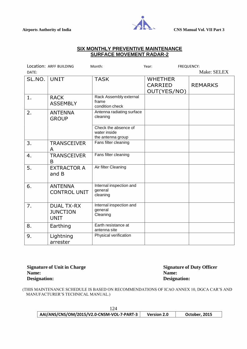
Airports Authority of India CNS Manual Vol. VII Part 3
124
AAI/ANS/CNS/OM/2015/V2.0-CNSM-VOL-7-PART-3 Version 2.0 October, 2015
SIX MONTHLY PREVENTIVE MAINTENANCE
SURFACE MOVEMENT RADAR-2
Location: ARFF BUILDING Month: Year: FREQUENCY:
DATE: Make: SELEX
SL.NO. UNIT TASK WHETHER
CARRIED
OUT(YES/NO)
REMARKS
1. RACK ASSEMBLY
Rack Assembly external frame condition check
2. ANTENNA GROUP
Antenna radiating surface cleaning
Check the absence of water inside the antenna group
3. TRANSCEIVER A
Fans filter cleaning
4. TRANSCEIVER B
Fans filter cleaning
5. EXTRACTOR A
and B
Air filter Cleaning
6. ANTENNA CONTROL UNIT
Internal inspection and general cleaning
7. DUAL TX-RX
JUNCTION
UNIT
Internal inspection and general Cleaning
8. Earthing Earth resistance at antenna site
9. Lightning arrester
Physical verification
Signature of Unit in Charge Signature of Duty Officer
Name: Name:
Designation: Designation:
(THIS MAINTENANCE SCHEDULE IS BASED ON RECOMMENDATIONS OF ICAO ANNEX 10, DGCA CAR’S AND
MANUFACTURER’S TECHNICAL MANUAL.)

Airports Authority of India CNS Manual Vol. VII Part 3
125
AAI/ANS/CNS/OM/2015/V2.0-CNSM-VOL-7-PART-3 Version 2.0 October, 2015
PREVENTIVE MAINTENANCE SCHEDULE - YEARLY SURFACE MOVEMENT RADAR-2
Location: ARFF BUILDING Month: Year: FREQUENCY:
DATE: Make: SELEX
SL.NO. UNIT TASK WHETHER CARRIED OUT(YES/NO)
REMARKS
1. Rack Assembly Rack Assembly cables and connectors condition check
2. Antenna Group Ground connection check
Motor belt tightening check
Fastening screws cleaning
3. Transceiver A and B
Internal inspection and general cleaning
4. System Cables and connectors check
Flexible waveguide check
Signature of Unit in Charge Signature of Duty Officer
Name: Name:
Designation: Designation:
(THIS MAINTENANCE SCHEDULE IS BASED ON RECOMMENDATIONS OF ICAO ANNEX 10, DGCA CAR’S AND
MANUFACTURER’S TECHNICAL MANUAL.)

Airports Authority of India CNS Manual Vol. VII Part 3
126
AAI/ANS/CNS/OM/2015/V2.0-CNSM-VOL-7-PART-3 Version 2.0 October, 2015
Device Status
on CMS
Indication
on LMDT
Comm. CPF Comm. MTP
MLAT Receiver 1 CPF A CPF B
MLAT Receiver 2 MTP A MTP B
MLAT Receiver 3 Mode-S-INT
MLAT Receiver 4
MLAT Receiver 5
MLAT Transmitter
MLAT SGU 1
MLAT SGU 2
DAILY PREVENTIVE MAINTENANCE MLAT STATUS ON LMDT
OPERATIONAL STATUS
DATE: Indication Status of CPF:
Operative Status of CPF:
CPF SEC. Extractor A/B
MTP ( RHP) A/B
Selection Whether Plots/Tracks are
available on Main screen
Whether Plots/Tracks are
available on TRP screen
With Mode-S selection
With ADS-B selection
Signature of Unit in Charge Signature of Duty Officer
Name & Designation: Name & Designation:
(THIS MAINTENANCE SCHEDULE IS BASED ON RECOMMENDATIONS OF ICAO ANNEX 10, DGCA CAR’S AND
MANUFACTURER’S TECHNICAL MANUAL.)
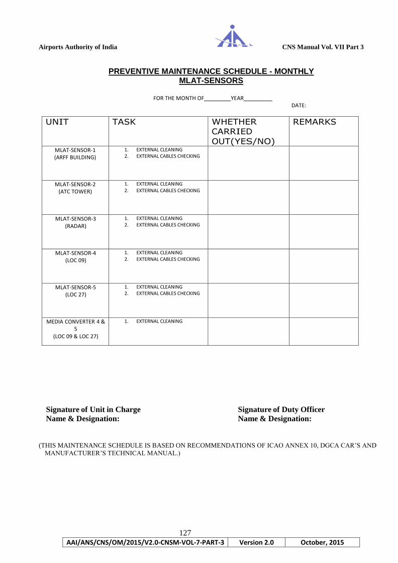
Airports Authority of India CNS Manual Vol. VII Part 3
127
AAI/ANS/CNS/OM/2015/V2.0-CNSM-VOL-7-PART-3 Version 2.0 October, 2015
PREVENTIVE MAINTENANCE SCHEDULE - MONTHLY MLAT-SENSORS
FOR THE MONTH OF YEAR
DATE:
UNIT TASK WHETHER CARRIED
OUT(YES/NO)
REMARKS
MLAT-SENSOR-1 (ARFF BUILDING)
1. EXTERNAL CLEANING 2. EXTERNAL CABLES CHECKING
MLAT-SENSOR-2 (ATC TOWER)
1. EXTERNAL CLEANING 2. EXTERNAL CABLES CHECKING
MLAT-SENSOR-3 (RADAR)
1. EXTERNAL CLEANING 2. EXTERNAL CABLES CHECKING
MLAT-SENSOR-4 (LOC 09)
1. EXTERNAL CLEANING 2. EXTERNAL CABLES CHECKING
MLAT-SENSOR-5 (LOC 27)
1. EXTERNAL CLEANING 2. EXTERNAL CABLES CHECKING
MEDIA CONVERTER 4 & 5
(LOC 09 & LOC 27)
1. EXTERNAL CLEANING
Signature of Unit in Charge Signature of Duty Officer
Name & Designation: Name & Designation:
(THIS MAINTENANCE SCHEDULE IS BASED ON RECOMMENDATIONS OF ICAO ANNEX 10, DGCA CAR’S AND
MANUFACTURER’S TECHNICAL MANUAL.)

Airports Authority of India CNS Manual Vol. VII Part 3
128
AAI/ANS/CNS/OM/2015/V2.0-CNSM-VOL-7-PART-3 Version 2.0 October, 2015
PREVENTIVE MAINTENANCE SCHEDULE - WEEKLY MLAT-SENSORS
DATE:
MODULES: DIGITAL UNIT SYNTHESIZ
ER MODUATO
R POWER
SUPPLY 1 POWER
SUPPLY 2
MLAT UNIT LA
N T
X R
X AL
R SYNTH
_LOCK LOCK T
X LOC
K VC
C LIN
E VC
C LIN
E REMA
RKS
SENSOR 1(ARFF)
SENSOR 2
(TOWER)
SENSOR 3
(RADAR)
SENSOR 4 (LOC
27)
SENSOR 5 (LOC
09)
UNIT LED
INDICATION
REMARKS
100 Base Tx
Side
100 Base
Fx side PW R
M/ L ON
FDX LNK ACT LNK ACT
MEDIA-CONVERTER
1 (LOC 27)
MEDIA-CONVERTER
2 (LOC 09)
Signature of Unit in Charge Signature of Duty Officer
Name & Designation: Name & Designation:
(THIS MAINTENANCE SCHEDULE IS BASED ON RECOMMENDATIONS OF ICAO ANNEX 10, DGCA CAR’S AND
MANUFACTURER’S TECHNICAL MANUAL.)

Airports Authority of India CNS Manual Vol. VII Part 3
129
AAI/ANS/CNS/OM/2015/V2.0-CNSM-VOL-7-PART-3 Version 2.0 October, 2015
Chapter -5
Maintenance Schedules
ADS-B

Airports Authority of India CNS Manual Vol. VII Part 3
130
AAI/ANS/CNS/OM/2015/V2.0-CNSM-VOL-7-PART-3 Version 2.0 October, 2015
Preventive Maintenance Schedule (ADS-B) - Daily
Make : COMSOFT Date : Parameters Normal Indication Observed Indication (Color/Status)
/Remarks
I. GENERAL
a) Cleanliness O.K.
b) Room Temperature < 25 Deg. Celsius
c) Humidity 20% to 80%
d) Room lighting O.K.
e) Air conditioner Status All AC working normal
II. ESMS APPLICATION
Analyze the ESMS Alarm panel Messages, Events Log & take corrective action
No Active Alarms
i) ADS-B Equipment Status
Sensor-A C-State Black Bk Bl R
E-State Green G W R Y O Bl
Sensor-B C-State Black Bk Bl R
E-State Green G W R Y O Bl
Site Monitor C-State Black Bk Bl R
E-State Green G W R Y O Bl
ii) Center Status
QIC E-State Green G W R Y O Bl
Go/No-Go Status Go
Server H/W E-State Green G W R Y O Bl
Disk usage < 80%
ESMS S/W E-State Green G W R Y O Bl
III. QIC APPLICATION
Site Monitor Transmission in DF-18 OK
IV. QCMS APPLICATION
i) Sensor-A Monitoring
Sensor data updating Normal
Temperature -20º C to 70º C
CPU Load 0% to 70%
GPS Connected Yes
ii) Sensor-B Monitoring
Sensor data updating Normal
Temperature -20º C to 70º C
CPU Load 0% to 70%
GPS Connected Yes
V. QCMS PC Time Check
Time synchronization with GPS Time OK
VI. CONNECTOR-BOX
Status of +24V Power Supply-1 DC OK LED- Green
Status of +24V Power Supply-2 DC OK LED- Green
Switch-1 Status Power LED-Green & Other connected Links blinking
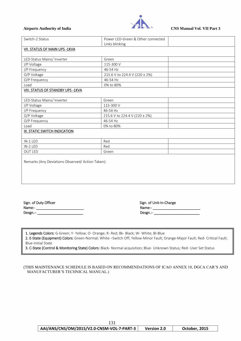
Airports Authority of India CNS Manual Vol. VII Part 3
131
AAI/ANS/CNS/OM/2015/V2.0-CNSM-VOL-7-PART-3 Version 2.0 October, 2015
Switch-2 Status Power LED-Green & Other connected Links blinking
VII. STATUS OF MAIN UPS -1KVA
LED-Status Mains/ Inverter Green
I/P Voltage 115-300 V
I/P Frequency 46-54 Hz
O/P Voltage 215.6 V to 224.4 V (220 ± 2%)
O/P Frequency 46-54 Hz
Load 0% to 80%
VIII. STATUS OF STANDBY UPS -1KVA
LED-Status Mains/ Inverter Green
I/P Voltage 115-300 V
I/P Frequency 46-54 Hz
O/P Voltage 215.6 V to 224.4 V (220 ± 2%)
O/P Frequency 46-54 Hz
Load 0% to 80%
IX. STATIC SWITCH INDICATION
IN-1 LED Red
IN-2 LED Red
OUT LED Green
Remarks (Any Deviations Observed/ Action Taken):
Sign. of Duty Officer Sign. of Unit-In-Charge Name:- ________________________ Name:- ________________________ Desgn.:- _______________________ Desgn.:- _______________________
(THIS MAINTENANCE SCHEDULE IS BASED ON RECOMMENDATIONS OF ICAO ANNEX 10, DGCA CAR’S AND
MANUFACTURER’S TECHNICAL MANUAL.)
1. Legends Colors: G-Green; Y- Yellow; O- Orange; R- Red; Bk- Black; W- White; Bl-Blue 2. E-State (Equipment) Colors: Green-Normal; White –Switch Off; Yellow-Minor Fault; Orange-Major Fault; Red- Critical Fault; Blue-Initial State 3. C-State (Control & Monitoring State) Colors: Black- Normal acquisition; Blue- Unknown Status; Red- User Set Status

Airports Authority of India CNS Manual Vol. VII Part 3
132
AAI/ANS/CNS/OM/2015/V2.0-CNSM-VOL-7-PART-3 Version 2.0 October, 2015
Preventive Maintenance Schedule (ADS-B) – Monthly
Make : Comsoft Date :
Remarks if any
Sign. of Duty Officer Sign. of Unit-In-Charge Name:- ________________________ Name:- ________________________ Desgn.:- _______________________ Desgn.:- _______________________
(THIS MAINTENANCE SCHEDULE IS BASED ON RECOMMENDATIONS OF ICAO ANNEX 10, DGCA CAR’S AND
MANUFACTURER’S TECHNICAL MANUAL.)
SL NO STATUS / PARAMETERS NORMAL STATUS OBSERVED STATUS
Sensor A Sensor B
1. Sensor Configuration
1.a GPS Latitude deg
1.b GPS Longitude deg
1.c GPS Geodial Height meters
2. Power on Self Test (POST) Results
2.a General Result Passed
2.b GPS Passed
2.c Temp Sensing Passed
2.d Voltage Sensing Passed
2.e FPGA Passed
2.f Receiver Passed
3. System Status Information (Maintenance Mode)
3.a CPU Load 0%-75%
3.b GPS Status Yes
3.c GPS Synchronized yes
3.1 Voltages & Temperature
3.1.a Intermediate volt (+ ve) 9.5 v to 13.5 v
3.1.b Intermediate volt (- ve) -13.5 v to -9.5 v
3.1.c GPS Voltage 9.5 v to 13.5 v
3.1.d FPGA Core Voltage 1.0 v to 1.4 v
3.1.e FPGA Auxiliary Voltage 2.3 v to 2.7 v
3.1.f DSP Board Voltage 3.1 v to 3.5 v
3.1.g DSP Board Temperature -20 to 70 deg C
3.2 Site Monitor Statistics
3.2.a Signal Strength of last RF Site Mon Msg
0-255
3.3 End to End Test Results
3.3.a End to End Test Passed
3.3.b Rx Sensitivity Passed
3.3.c Test Transmission Loss Passed
3.3.d Decoder Test Passed
3.4 Device Status
3.4.a Gnd Station Status Go
3.4.b Overall build-in-test result
No Error Pending
3.4.c UTC Synchronization State
UTC Coupled

Airports Authority of India CNS Manual Vol. VII Part 3
133
AAI/ANS/CNS/OM/2015/V2.0-CNSM-VOL-7-PART-3 Version 2.0 October, 2015
UPS Monthly Maintenance Schedule (ADS-B)
Make : Eaton, 1 KVA Date :
Battery No. UPS-1 UPS-2 Mains OFF After 30
Minutes Mains OFF After 30
Minutes
1.
2.
3.
OVERALL VOLTAGE
CHARGING /DISCHARGING CURRENT
REMARKS
Sign of Duty Official Sign of Unit In-charge Name & Design: Name & Design:
(THIS MAINTENANCE SCHEDULE IS BASED ON RECOMMENDATIONS OF ICAO ANNEX 10, DGCA CAR’S AND
MANUFACTURER’S TECHNICAL MANUAL.)

Airports Authority of India CNS Manual Vol. VII Part 3
134
AAI/ANS/CNS/OM/2015/V2.0-CNSM-VOL-7-PART-3 Version 2.0 October, 2015
Preventive Maintenance Schedule (ADS-B)- Quarterly
Make : Comsoft Date :
S/N Parameters Normal Status Observation
1 Preventive Maintenance of ADS-B Sensors and Site Monitor
1.1 ADS-B Sensor-1
1.1.a Physical check of Antenna, Associated cables and connectors
OK
1.1.b Physical check of GPS Antenna, Associated cables and connectors
OK
1.1.c Physical check of LAN Cables OK
1.1.d Physical check of Power Cables OK
1.2 ADS-B Sensor-2
1.2.a Physical check of Antenna, Associated cables and connectors
OK
1.2.b Physical check of GPS Antenna, Associated cables and connectors
OK
1.2.c Physical check of LAN Cables OK
1.2.d Physical check of Power Cables OK
1.3 Site Monitor
1.3.a Physical check of Antenna, Associated cables and connectors
OK
1.3.b Physical check of GPS Antenna, Associated cables and connectors
OK
1.3.c Physical check of LAN Cables OK
1.3.d Physical check of Power Cables OK
1.3.e Power ON LED Green
1.3.f Link LED Orange
1.3.g Transmission LED Blue-Flashing
1.4 Connector BOX
1.4.a Physical check of RDCU cables and connectors OK
1.4.b Physical check of power cables and connectors OK
2 Preventive Maintenance of QCMS PC along with keyboard and mice as required is carried out.

Airports Authority of India CNS Manual Vol. VII Part 3
135
AAI/ANS/CNS/OM/2015/V2.0-CNSM-VOL-7-PART-3 Version 2.0 October, 2015
3 Condition of Earth pit :
Particulars Normal Status Observation
3.1 Earth pit (For ADS-B Sensors and Site Monitor)
i) Physical condition of Earth pit, electrical connection & copper strips.
ii) Area surrounding the earth pits clear of dense grass, shrubs & other obstructions.
3.2
Earth resistance value Earth resistance value measured on DD/MM/YY.
< 2 Ω
4 Earth-Neutral Voltage (UPS)
Sign. of Manager Sign. of Unit-In-Charge Name:- ________________________ Name:- _______________________ Desgn.:- _______________________ Desgn.:- _______________________
(THIS MAINTENANCE SCHEDULE IS BASED ON RECOMMENDATIONS OF ICAO ANNEX 10, DGCA CAR’S AND
MANUFACTURER’S TECHNICAL MANUAL.)