author biographies ieee/acm trans- - university of california
TRANSCRIPT

20
[11] S. Floyd and V. Jacobson. Random Early DetectionGateways for Congestion Avoidance. IEEE/ACM Trans-actions on Networking, 1(4):397–413, August 1993.
[12] V. Jacobson. Congestion Avoidance and Control. InProc. ACM SIGCOMM 88, August 1988.
[13] V. Jacobson. Compressing TCP/IP Headers for Low-Speed Serial Links, February 1990. RFC 1144.
[14] R. Jain. The Art of Computer Systems PerformanceAnalysis. John Wiley and Sons, 1991.
[15] L. Kalampoukas, A. Varma, and K. K. Ramakrishnan.Performance of Two-Way TCP Traffic over AsymmetricAccess Links. In Proc. Interop ’97 Engineers’ Confer-ence, May 1997.
[16] P. Karn. MACA – A New Channel Access Method forPacket Radio. In Proc. 9th ARRL Computer NetworkingConference, 1990.
[17] P. Karn. Dropping TCP acks. Mail to the end-to-endmailing list, February 1996.
[18] T. V. Lakshman, U. Madhow, and B. Suter. Window-based Error Recovery and Flow Control with a SlowAcknowledgement Channel: A study of TCP/IP Perfor-mance. In Proc. Infocom 97, April 1997.
[19] M. K. McKusick, K. Bostic, M. J. Karels, and J. S.Quarterman. The Design and Implementation of the 4.4BSD Operating System. Addison-Wesley, Reading, MA,1996.
[20] UCB/LBNL/VINT Network Simulator - ns (version 2).http://www-mash.cs.berkeley.edu/ns/.
[21] V. N. Padmanabhan. Addressing the Challenges of WebData Transport. PhD thesis, University of California atBerkeley, September 1998. Also available as TechnicalReport UCB/CSD-98-1016.
[22] V. N. Padmanabhan, H. Balakrishnan, K. Sklower,E. Amir, and R. H. Katz. Networking Using DirectBroadcast Satellite. In Proc. Workshop on Satellite-Based Information Systems, November 1996.
[23] V. N. Padmanabhan and J. C. Mogul. Improving HTTPLatency. In Proc. Second International World Wide WebConference, October 1994.
[24] L. Zhang, S. Shenker, and D. D. Clark. Observations andDynamics of a Congestion Control Algorithm: TheEffects of Two-Way Traffic. In Proc. ACM SIGCOMM’91, pages 133–147, 1991.
Author Biographies
Hari Balakrishnan is an Assistant Professor of EECS and a mem-ber of the Laboratory for Computer Science at the MassachusettsInstitute of Technology. He received his M.S. and Ph.D. degrees inComputer Science from the University of California at Berkeley in1995 and 1998 respectively, and a B. Tech. in Computer Scienceand Engineering from the Indian Institute of Technology (Madras)in 1993.
Hari’s research interests are in the areas of computer networks andprotocol architectures, wireless networks and mobile systems,adaptive network applications, and large-scale communication sys-tems. He has received awards for papers at the ACM/IEEE Mobi-com Conference and the Usenix Technical Conference. He is alsoa recipient of the C. V. Ramamoorthy award for distinguishedgraduate research at Berkeley and the winner of a Segasoftresearch grant from the Okawa Foundation. He is a member of theACM and the IEEE. His email address is [email protected] and hisWWW URL is http://www.sds.lcs.mit.edu/~hari
Venkata N. Padmanabhan (ACM ‘94, IEEE ‘94) is a Researcherin the Systems and Networking group at Microsoft Research. Hereceived his B.Tech. degree in Computer Science and Engineer-ing at the Indian Institute of Technology, Delhi in 1993, and hisM.S. and Ph.D. degrees in Computer Science at the University ofCalifornia at Berkeley in 1995 and 1998, respectively.
Venkat’s research interests are in the areas of Computer Networks,Mobile Computing, and Operating Systems. The focus of hisPh.D. dissertation was on developing network protocols for effi-cient Web access and effective data transport over asymmetric net-works. His work on persistent-connection HTTP has been adoptedby the HTTP/1.1 standard. Among the awards he has received arethe National Talent Scholarship in India, the Charles Fish fellow-ship at Berkeley, and the best student paper award at the Usenix‘95 conference . Venkat may be reached v ia e -mai l a tpadmanab@microsof t . com and on the Web a t h t tp : / /
www.research.microsoft.com/~padmanab.
Randy H. Katz (ACM F ’96, IEEE F ’96) is a professor of com-puter science at the University of California at Berkeley, and is aprincipal investigator in the Bay Area Research Wireless AccessNetwork (BARWAN) project. He has taught at Berkeley since1983, with the exception of 1993 and 1994 when he was a programmanager and deputy director of the Computing Systems Technol-ogy Office at the Defense Department’s Advanced ResearchProjects Agency. He has written over 130 technical publications onCAD, database management, multiprocessor architectures, highperformance storage systems, video server architectures, and com-puter networks.
Dr. Katz received a B.S. degree at Cornell University, and an M.S.and a Ph.D. at the University of California at Berkeley, all in com-puter science. His e-mail address is [email protected] and hisWWW home page is http://www.cs.berkeley.edu/~randy.

19
Our methodology has involved three major steps. First, we mea-sured the various asymmetric networks, including the Hybrid wire-less cable network and the Ricochet packet radio network, toidentify performance bottlenecks. Then, we modeled these net-works in the ns simulator and experimented with several tech-niques to improve performance. Finally, we implemented thepromising techniques in our experimental testbed and confirmedthe performance trends observed in the simulations.
The following are our main results:
• SLIP header compression [13] alleviates some of the problemsdue to bandwidth asymmetry, but does not completely elimi-nate all problems, especially those that arise in the presence ofbidirectional traffic.
• Connections traversing packet radio networks suffer from largevariations in round-trip times caused by the half-duplex natureof the radios and asymmetries in the media-access protocol,which lead to variable latencies. This adversely affects TCP’sloss recovery mechanism and results in degraded performance.
• The various end-to-end and router-based techniques that wepropose help improve performance significantly in manyasymmetric situations. We have verified this both via simula-tions and via experiments on the real testbed. These includedecreasing the frequency of acks on the constrained reversechannel (ack congestion control and ack filtering), reducingsource burstiness when acks are infrequent (TCP sender adap-tation and ack reconstruction), and scheduling data and acksintelligently at the reverse bottleneck router (acks-first schedul-ing).
• In addition to improving throughput for individual connec-tions, our proposed modifications also help improve the fair-ness and scaling properties when several connections contendfor scarce resources in the network. We have demonstrated thisvia simulations of bulk and Web-like transfers.
Finally, we note that asymmetric networks are becoming increas-ingly important both in the mass market (e.g., Internet access to thehome via cable modems) and in specialized situations (e.g., battle-field communications via mobile ad hoc networks). Therefore, webelieve that the findings reported in this paper are relevant in awide context.
11. Future Work
There are several areas of future work that we plan to investigate.
• The asymmetry in loss and error rates, especially in the contextof wireless return channels, poses new challenges. Currentpacket radio networks use link-layer protocols for local errorrecovery, but this results in increased latency and variability inlatency. We plan to extend Explicit Loss Notification (ELN)schemes proposed in the context of single-hop cellular net-works [3] to multi-hop wireless networks, with the goal ofreducing variability without sacrificing local error recovery.
• Cellular Digital Packet Data (CDPD) networks exhibit media-access asymmetry. Communication from the base station to theend stations is unimpeded, but end stations contend with eachother for channel access in the reverse direction. It will beinformative and useful to study the impact of this asymmetryon reliable transport performance.
12. Acknowledgments
We are grateful to several people for their help in setting up anddebugging various networks in our experimental testbed: Mike Rit-ter, Mike Cunningham, Bob Luxemburg, Will SanFilippo, DavidPaulsen, and Sheela Rayala (Metricom, Inc.); Ed Moura (HybridNetworks, Inc.); Andrew Nestor (MetroNet, Inc.); and Ken Lutz,Steve Hawes, and Fred Archibald (UC Berkeley). We appreciatetheir time and assistance.
We thank Mary Baker, Sally Floyd, Tom Henderson, Mike Ritter,Srinivasan Seshan, Andrew Swan, and the anonymous Mobicomreviewers for several comments and suggestions that helpedimprove the quality of this paper. Our special thanks to GiaoNguyen for his contributions to ns, which greatly facilitated ourwork.
This work was supported by DARPA contract DAAB07-95-C-D154, by the State of California under the MICRO program, andby the Hughes Aircraft Corporation, Metricom, Fuji Xerox, Daim-ler-Benz, Hybrid Networks, and IBM. Hari is partially supportedby a research grant from the Okawa Foundation.
13. References
[1] A. Bakre and B. R. Badrinath. Handoff and System Sup-port for Indirect TCP/IP. In Proc. Second Usenix Symp.on Mobile and Location-Independent Computing, April1995.
[2] H. Balakrishnan. Challenges to Reliable Data Transportover Heterogeneous Wireless Networks. PhD thesis, Uni-versity of California at Berkeley, August 1998. Alsoavailable as Technical Report UCB/CSD-98-1010.
[3] H. Balakrishnan, V. N. Padmanabhan, S. Seshan, andR.H. Katz. Comparing the Performance of TransportProtocols in Wireless Networks. In Proc. ACM SIG-COMM ’96, August 1996.
[4] H. Balakrishnan, S. Seshan, and R.H. Katz. ImprovingReliable Transport and Handoff Performance in CellularWireless Networks. ACM Wireless Networks, 1(4),December 1995.
[5] Berkeley Software Design, Inc. http://www.bsdi.com.
[6] R. Caceres and L. Iftode. Improving the Performance ofReliable Transport Protocols in Mobile Computing Envi-ronments. IEEE Journal on Selected Areas in Communi-cations, 13(5), June 1995.
[7] S. Cheshire and M. Baker. A Wireless Network in Mos-quitoNet. IEEE Micro, Feb 1996.
[8] D-M. Chiu and R. Jain. Analysis of the Increase andDecrease Algorithms for Congestion Avoidance in Com-puter Networks. Computer Networks and ISDN Systems,17:1–14, 1989.
[9] R. Durst, G. Miller, and E. Travis. TCP Extensions forSpace Communications. In Proc. ACM Mobicom Con-ference, November 1996.
[10] R. Fielding, J. Gettys, J. Mogul, H. Frystyk, andT. Berners-Lee. Hypertext Transfer Protocol – HTTP/1.1. RFC, Jan 1997. RFC-2068.

18
9.1.2 ACC: Effect of max_delack
With ACC, the parameter max_delack determines the minimumfrequency of acks from the receiver. Since max_delack is an upperbound on delack, the receiver has to send at least 1 ack everymax_delack segments of data that it receives.
We conducted a set of 3 MB data transfers similar to the ones dis-cussed above, but varied max_delack between 2 and 16 over thedifferent sets of runs. The throughput obtained is plotted againstmax_delack in Figure 21.
As max_delack is increased, throughput also increases initially.The reason for this is that the decreasing frequency of acks allevi-ates congestion of acks on the reverse channel. However, beyondmax_delack equal to 8, there is little increase in throughput, pre-sumably because congestion on the reverse channel has alreadybeen eliminated.
9.1.3 Effect of Two-way Traffic
In this experiment, we consider the situation of simultaneous trans-fers in the forward and reverse directions. As we observed in simu-lation experiments (Section 7.1.3), there are situations where datatransfer in one direction shuts out the one in the opposite direction.
In each run of our experiment, we first initiated a 3 MB data trans-fer in the forward direction, and 2-3 seconds later initiated a 100KB reverse transfer. For the forward-direction connection, max-burst was set to 4. Also, when ACC was used, max_delack was setto 8. In Figure 22, we report the throughputs of the forward andreverse transfers computed over the time during which both trans-fers were active.
The trends we observe are in conformance with the simulationresults reported in Section 7.1.3. With standard FIFO schedulingon the reverse channel, the large data packets of the reverse trans-fer tend to starve out the acks of the forward transfer, resulting inpoor forward throughput (0.35 Mbps with Reno, 0.16 Mbps withACC and 0.09 Mbps with AF). The decreased frequency of ackswith ACC and AF increases the chances that the sender of the for-ward transfer stalls waiting for acks to arrive, which explains theworse forward throughput in these cases as compared to Reno. Forthe same reason, the reverse throughputs show the opposite trend,
with a throughput with 10% of the 28.8 Kbps link speed in thecases of ACC and AF.
Using acks-first scheduling on the reverse channel helps improveforward throughput substantially. However, acks-first together withstandard TCP Reno hurts reverse throughput significantly (bring-ing it down to 5.1 Kbps). When acks-first is used in conjunctionwith a forward transfer that does ack filtering, the reverse transferis completely shut out, achieving zero throughput whereas the for-ward transfer achieves a high throughput of nearly 4 Mbps (equiv-alent to the one-way transfer case). The reason for the poorperformance of the reverse transfer in these two cases is that acksof the forward transfer are queued up in the reverse channel buffermost of the time. While such acks are present, data packets of thereverse transfer are not served at all because acks are given ahigher priority. Even ack filtering, which allows at most one suchack to reside in the reverse buffer, does not help because so long asa new ack arrives before the current one has completed transmis-sion, data packets of the reverse transfer do not get served.
When acks-first is used together with ACC, both the forward andreverse transfers achieve relatively good throughput (nearly 1.3Mbps and 20.1 Kbps respectively). We can repeat the calculationdone in Section 7.1.3 for the best possible forward throughputwhen the reverse throughput is close to the reverse link speed of28.8 Kbps. With 150 KB socket buffers and 1424-byte segments,this works out to 2.75 Mbps. The throughput actually achieved (1.3Mbps) is less than half this. We suspect that the shortfall is due to acombination of several factors, including the time it takes the for-ward connection’s congestion window to grow up to a largeenough value and the non-negligible transmission time for acks.We still investigating this matter to determine the reason(s) forsure.
10. Conclusions
In this paper, we investigated the effects on network asymmetry onTCP performance in the context of wide-area wireless networks.We studied the impact of the reverse path, used primarily foracknowledgments and data requests, on end-to-end performance inthe forward direction. We distinguished between bandwidth asym-metry, latency and media-access asymmetry, and loss asymmetry,and focused on the first two types.
Figure 21. Throughput of a 3 MB forward transfer versusmax_delack. The parameter min_acks_per_win = 5 and max-burst = 4 or 6. The data points show the average of 10 runsand the vertical bars correspond to +/- one standard devia-
tion.
Max delack (# segments)
Thr
ough
put
(Mbp
s)
0
1
2
3
4
5
6
0 2 4 6 8 10 12 14 16
G
G
G
G G G G
;
;
;
; ; ; ;
n
n
n
n
n
n n
5
5
5
5
5
5 5
maxburst = 6
maxburst = 4
Reno
Figure 22. Throughput of a 3 MB forward transfer and a 100KB reverse. The reverse transfer is initiated 2-3 seconds afterthe forward transfer. Only the time during which both trans-fers are active is considered for computing throughput. Notethat the reverse throughput is 0 for the “AF+Acksfirst” case.
Thr
ough
put
(Mbp
s)
Thr
ough
put
(Kbp
s)
0
0.5
1.0
1.5
2.0
2.5
3.0
3.5
4.0
0
5
10
15
20
25
30
35
40
Reno ACC Reno+ ACC+Acksfirst
AF AF+Acksfirst
Forward
Reverse
0.35
20.3
1
0.16
25.3
1
1.45
5.10
1.29
20.0
8
0.09
26.7
03.
93
0.00
Acksfirst

17
sender. We could do so by adding a TCP option that specified thenumber of purged duplicate acks and propagating that to the senderfrom the router, and by modifying the sender to recognize andreact to this option.
When we implemented this mechanism and deployed it, we foundthat the queueing of packets occurs inside the modem and not inthe kernel’s PPP queue, with both the Ricochet and standard tele-phone modems. Therefore, in our experiments bandwidth asym-metry with AF, we emulated the modem link in software. Since inthis case packets are not compressed, we can offset to the TCP andIP headers and purge redundant acks. For the experiments withlatency asymmetry, we are currently working with Metricom toobtain research modems with the ability to control queues on themodem and cause queueing to happen in the kernel’s PPP queue.We will be able to measure the benefits of our proposed enhance-ments once that happens.
9. Implementation Results
In this section, we present experimental results based on the imple-mentation described in Section 8. We present results of bandwidthasymmetry experiments here. We are currently in the process ofevaluating our improvements with latency asymmetry in ourexperimental Ricochet network. We expect to have performanceresults for this network in the next few weeks.
9.1 Bandwidth Asymmetry Experiments
At the time we conducted these experiments, the Hybrid wirelesscable modem network (Section 3.1) was unfortunately unavailable.Given the Ethernet-like characteristics of this network (10 Mbpsraw bandwidth, 2 ms latency, negligible error rate), we decided tosubstitute it with an Ethernet segment for the forward channel. Weused a 28.8 Kbps dialup reverse channel for all experiments exceptthose involving ack filtering. For the reasons mentioned inSection 8, we emulated a dialup-like link (with 28 Kbps bandwidthand 80 ms one-way latency) in software for the ack filtering exper-iments. The size of the reverse channel buffer was set to 32 pack-ets, the default for a PPP dialup interface under BSDI 3.0.
Standard header compression [13] was enabled on the dialupreverse channel. However, upon tracing through the code, we dis-covered that the compression code was never being invokedbecause as it stands it cannot deal with TCP headers that includeoptions (such as the timestamp option) that change in value fromone segment to the next. It is possible in principle to change thecompression algorithm to accommodate TCP options. But this wasnot feasible in our situation because we had no control over termi-nal server we were dialing in to. However, we observe that in a sit-uation were it is feasible to deploy a link-local scheme such as AF/AR, it should also be possible to deploy a new header compressionalgorithm.
Each experiment described below involves one or both of a TCPdata transfer in the forward direction and one in the reverse direc-tion. The length of the forward transfer was 3 MB and the senderand receiver socket buffer sizes were set to 150 KB. The length ofthe reverse transfer was 100 KB and the sender and receiver socketbuffer sizes were set to 100 KB also. The TCP maximum segmentsize (MSS) was set to 1424 bytes for transfers in both directions.
9.1.1 Sender Adaptation: Effect of maxburst
The parameter maxburst determines the size of the largest burst(i.e., sequence of back-to-back packets) that a sender could trans-
mit. This parameter is of significance when the sender receivesacks infrequently, as is the case with ack congestion control or ackfiltering.
Each run of our experiment involved a 3 MB data transfer in theforward direction. We did 10 runs for each value of maxburst rang-ing from 1 through 10. We also conducted a set of runs with max-burst set to infinity which corresponds to there being no limit onthe burst size.
Figure 20 plots the throughput of the forward direction data trans-fer versus maxburst with ACC and AF. The throughput increasessteadily at first and then either levels off or drops off.
The initial increase corresponds to the situation where the through-put is limited by the 10 ms granularity of the software timer usedto schedule bursts. For example, when maxburst is set to 3, themaximum possible throughput is obtained by sending 3 segmentsevery 10 ms. With 1424-byte segments, this works out to athroughput of 3.4 Mbps. This explains why as maxburst isincreased from 1 through 4, the average throughput increasesalmost linearly.
The levelling off or the drop off of average throughput, and the sig-nificant increase in variability (as evidenced by the longer verticalbars), happen because as maxburst gets large, the large bursts resultin buffer overflow (most likely at the Ethernet network interfacecard) at least some of the time. The poor throughput on runs thatinvolve packet loss pulls down the average and increases variabil-ity.
Based on the data in Figure 20, it seems best to set maxburst to 4 or5. Standard TCP with delayed acks could send bursts of size 3 dur-ing slow start. Therefore, setting maxburst to 4 seems conservativeenough because it would result in bursts at most one larger thanalready happen in the Internet today.
Figure 20. Throughput of a 3 MB forward transfer versusmaxburst. For ACC, min_acks_per_win = 5 and max_delack = 8.
maxburst = Inf (infinity) means that there is no limit on theburst size. The data points show the average of 10 runs andthe vertical bars correspond to +/- one standard deviation.
Maxburst (# segments)
Thr
ough
put
(Mbp
s)
0
1
2
3
4
5
6
0 2 4 6 8 10 Inf
G
G
G
G
G GG
G G GG
;
;
;
;
; ;;
; ; ;;
n
n
n
n
nn
n nn
n n
5
5
5
5
55
5 55
5 5
ACC
AF
Reno
16
min_acks_per_win. Finally, the receiver makes sure that delackdoes not exceed the preset limit of max_delack.
The standard delayed ack timer is still used just as before. Thereceiver forces out an ack if and when this timer expires. Since thisonly happens infrequently, these forced acks are not a significantaddition to the reverse direction traffic.
To summarize, our implementation of ack congestion control oper-ates purely in an end-to-end mode with no special role played bythe routers in between. While this simplifies the implementation, itrequires the user/system administrator to configure the delack andmin_acks_per_win parameters on hosts that expect to see asymmet-ric connectivity.
8.3 Sender Adaptation
The goal of sender adaptation is to enable the TCP sender to oper-ate successfully even when the frequency of acks is decreased as aresult of ack congestion control or ack filtering. There are twoaspects to sender adaptation:
1. Tying congestion window growth to the amount of dataacknowledged rather than the number of ack packetsreceived.
2. Avoiding large bursts of data when each ack acknowledgeseveral new data segments.
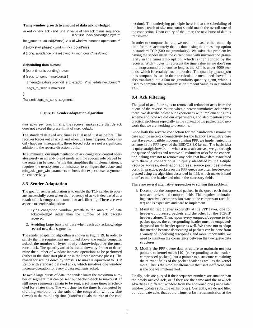
The sender adaptation algorithm is shown in Figure 19. In order tosatisfy the first requirement mentioned above, the sender computesacked, the number of bytes newly acknowledged by the mostrecent ack. The quantity acked is scaled down by 2*mss to deter-mine the number of window increase operations to be performed(either in the slow start phase or in the linear increase phase). Thereason for scaling down by 2*mss is to make it equivalent to TCPReno with standard delayed acks, which involves one windowincrease operation for every 2 data segments acked.
To avoid large bursts of data, the sender limits the maximum num-ber of segment that can be sent out back-to-back to maxburst. Ifstill more segments remain to be sent, a software timer is sched-uled for a later time. The wait time for the timer is computed bydividing maxburst by the ratio of the congestion window size(cwnd) to the round trip time (cwnd/rtt equals the rate of the con-
nection). The underlying principle here is that the scheduling ofthe bursts (each of size maxburst) should match the overall rate ofthe connection. Upon expiry of the timer, the next burst of data istransmitted.
In order to compute the rate, we need to measure the round triptime far more accurately than is done using the timestamp optionin standard TCP (500 ms granularity). We solve this problem byhaving the sender insert the current time with microsecond granu-larity in the timestamp option, which is then echoed by thereceiver. With 4 bytes to represent the time value in, we don’t runinto wrap-around problems so long as the RTT is under 4000 sec-onds, which is certainly true in practice. The quantity t_exact_srttthus computed is used in the rate calculation mentioned above. It isalso translated into a 500 ms granularity quantity, t_srtt, which isused to compute the retransmission timeout value as in standardTCP.
8.4 Ack Filtering
The goal of ack filtering is to remove all redundant acks from thequeue of the reverse router, when a newer cumulative ack arrivesthere. We describe below our experiences with implementing thisscheme and how we did our experiments, and also mention somepractical problems especially in the context of the packet radio net-work that we are working to overcome.
Since both the reverse connection for the bandwidth asymmetrycase and the network connectivity for the latency asymmetry caseuse Hayes-compatible modems running PPP, we implemented thisscheme in the PPP layer of the BSD/OS 3.0 kernel. The basic ideais quite straightforward — when a new ack arrives, we go throughthe queue of packets and remove all redundant acks for the connec-tion, taking care not to remove any acks that have data associatedwith them. A connection is uniquely identified by the 4-tuple<source address, destination address, source port, destinationport>. In practice, packets on the PPP queue are often header-com-pressed using the algorithm described in [13], which makes it hardto offset into the header and obtain the necessary fields.
There are several alternative approaches to solving this problem:
1. Decompress the compressed packets in the queue each time anew ack arrives and compare fields. This requires maintain-ing extensive decompression state at the compressor (ack fil-ter) and is expensive and hard to implement.
2. Maintain two queues explicitly at the PPP layer, one forheader-compressed packets and the other for the TCP/IPheaders alone. Then, upon every enqueue/dequeue to thepacket queue, the corresponding header must be enqueued/dequeued on the header queue as well. We chose not to adoptthis method because dequeueing of packets can be done froma variety of underlying disciplines, and more importantly, weneed to maintain the consistency between the two queue datastructures.
3. Modify the PPP queue data structure to maintain not justpointers to kernel mbufs [19] (corresponding to the header-compressed packets), but a pointer to a structure containingthe relevant fields of the packet header as well as the kernelmbuf. This is the simplest alternative that isn’t inefficient, andis the one we implemented.
Finally, acks are purged if their sequence numbers are smaller thanthe newly arrived ack, or if they are the same and the new ackadvertises a different window from the enqueued one (since laterwindow updates subsume earlier ones). Currently, we do not filterout duplicate acks that could trigger a fast retransmission at the
Figure 19. Sender adaptation algorithm
Tying window growth to amount of data acknowledged:
acked <- new_ack - snd_una /* value of new ack minus sequence# of first unacknowledged byte */
incr_count <- acked/(2*mss) /* # of window increase operations */
if (slow start phase) cwnd += incr_count*mss
if (cong. avoidance phase) cwnd += incr_count*mss/cwnd
Scheduling data bursts:
if (burst timer is pending) return
if (segs_to_send > maxburst) {
timeout(maxburst/(cwnd/t_srtt_exact)) /* schedule next burst */
segs_to_send = maxburst
}
Transmit segs_to_send segments

15
The link emulation code is structured as shown in Figure 17. Itoperates in two stages — bandwidth emulation first and then delayemulation. The reason for this separation is that the transmission ofthe individual packets happens in succession (i.e., two packets can-not overlap) but the propagation can happen concurrently.
To emulate bandwidth, the transmission time of the packet at thehead of the input queue is computed. A timer is set to expire at thetime when the transmission of this packet is supposed to end. Anypackets arriving in the mean time are queued up in the bandwidthemulation queue, and algorithms such as ack filtering or REDpacket marking can operate on the them. When the timer expires,the designated packet is moved over to the delay emulation queue.
This second queue used a callout queue data structure and operatesstrictly in FIFO order. The purpose of the queue is to insert a delay,corresponding to the propagation delay of the emulated link, intothe outgoing data path. This is done by setting timers correspond-ing to the propagation delay. Each time the timer expires, thepacket at the head of the queue is dequeued and handed down tothe device-dependent driver for actual transmission. If the calloutqueue still has other packets, a fresh timer is set corresponding tothe remaining propagation delay for the new packet at the head ofthe queue.
There are two issues that need to be considered in the context ofour link emulation algorithm. First, the transmission and propaga-tion due to the underlying physical channel are not considered. Webelieve this simplification is appropriate for emulating a slow linkover a fast physical channel (e.g., modem link over 10 Base-TEthernet), which is precisely our goal. Second, the granularity ofthe software clock in the BSDI operating system is 10 ms, whichlimits the accuracy with which we can schedule packets. Fortu-nately, for slow links with relatively large transmission and propa-gation delays, the 10 ms scheduling granularity becomes lesssignificant. Furthermore, when packets tend to get queued up at theinput queue of the emulated link, there is an increased possibilityfor the scheduling inaccuracies to cancel out over successive pack-ets (e.g., one packet may undershoot a bit and a later one mayovershoot a bit).
8.2 Ack Congestion Control
The basic objective of ACC is for the receiver to decrease the fre-quency of acks in order to alleviate congestion on the bandwidth-constrained reverse channel. In general, there are two modes whichthe receiver could operate in.
1. It could decrease the frequency of acks to the minimum pos-sible based on preset limits and information from the sender(as explained below), or
2. It could do so in response to explicit congestion notificationsfrom the reverse channel router.
In addition to changing the TCP algorithm at the receiving andsending sides, supporting both these modes of operation requiretwo changes to the on-the-wire protocol:
ECN bit: The TCP and IPv4 headers have no designated field forexplicit congestion notification from the routers to the end hosts.However, there are a few unused bits in the TCP header, and one ofthese could be used as the ECN bit. Note that this bit is neededonly if the receiver operates in the second mode mentioned above.
Sender Window Option: The ACC algorithm requires the TCPreceiver to have knowledge of the sender’s window size to makesure that the receiver does not decrease the frequency of acks tosuch an extent that the sender stalls. To convey this informationfrom the sender to the receiver, we added a peerwin TCP option.
The sender computes a 2-byte quantity which the minimum of itscongestion window size and the amount of data it has in its socketbuffer as a multiple of the maximum segment size (MSS), andinserts it into the peerwin option. Another 2 bytes of overheadmake the total length of the option 4 bytes. Since this option isadded only to packets traversing the high-bandwidth forward path,we do not believe that this 4-byte overhead is significant.
In our implementation, the receiver operates in the first mode men-tioned above, so the ECN bit is not required. The TCP receivermaintains the following additional variables in its protocol controlblock to do ACC:
• delack: the delayed ack factor. The receiver sends back one ackfor every delack segments received.
• max_delack: upper bound on delack. This can be set using auser-level configuration program.
• peerwin: the size of the peer’s window (expressed as a multipleof the MSS). This is updated each time a segment with thepeerwin option enabled is received from the sender. The senderfills in this option by computing the minimum of its congestionwindow size and the amount of data there is in its socket buffer
• min_acks_per_win: the minimum number of acks to send perwindow of data that the sender. Clearly, this should be set atleast to 1. However, it may have to be set to a somewhat largervalue to alleviate ill effects (such as sender stalls) due to delaysand/or losses that acks could experience as they travel from thereceiver to the sender.
In the BSDI implementation, the TCP receiver sends an ack everytime the receiving application reads in enough data (thereby clear-ing up enough space in the receive socket buffer) that at least 2segments’ worth of additional flow control window can be adver-tised to the sender. With ACC, the receiver checks for delack seg-ments of space instead of 2 segments.
The receiver dynamically computes delack as shown in Figure 18.It first computes the sender’s effective window size, w, as the mini-mum of peerwin and the receive socket buffer size (expressed as amultiple of the MSS). Since the receiver must send at leastmin_acks_per_win acks per window, delack is set to w divided by
Sender algorithm:
w <- min(cwnd, sb_dat) /* min. of congestion window and amountof data in send socket buffer */
w <- w/mss /* scale down by max. segment size tomake it a 2-byte quantity */
Send w in a peerwin TCP option to the receiver
Receiver algorithm:
Update the variable peerwin based on the TCP option received
w <- min(peerwin, sb_sz/mss) /* min. of sender’s window andreceiver’s socket buffer size */
delack <- w/min_acks_per_win /* send at least min_acks_per_winper window of data */
delack <- min(maxdelack, delack) /* upper bound on delack */
Send an ack every delack segments (instead of the every 2 seg-ments as is done with standard TCP delayed acks)
Figure 18. Sender and receiver algorithms for dynamicallycomputing delack for ack congestion control

14
measured performance (20 runs each). These controlled measure-ments were performed in the absence of any cross-traffic and theinherent variability of the return path manifests itself in the signifi-cant error-bars on the graph.
We focus on a Web-like benchmark in the following simulationsand study the performance of this network as the number of hostsand connections increases. We investigate the various modifica-tions to the transport and router protocols to help reduce the aver-age completion time of a Web request in such networks.
We model the Web micro-benchmark as a 500 byte Web requestfollowed by set of 4 concurrent TCP transfers of 10 KB each to theclient. This is not intended to be an accurate model of reality, butrather to understand the effects of small and concurrent connec-tions, as well as competing and interacting users, on performance.Since latency is a critical factor that impacts performance in thepacket radio network, we implicitly assume that the Web requestsuse pipelining [23] and that one 500 byte request results in 4 down-loads.
We vary the number of hosts from 1 to 50 in the simulations. Hostsmake requests independent of each other at a time uniformly dis-tributed in [0,5] seconds. We measure the mean and standard devi-ation of the completion time for the entire Web transaction (i.e., all4 connections).
Figure 16 shows the mean completion time for a transaction as thenumber of hosts varies, for TCP Reno, Reno with ACC(Section 6.1) and Reno with AF (Section 6.2). Two curves areshown for the AF case — with sender adaptation enabled based onthe round-trip time and the congestion window, and without(Section 6.3). These results indicate that AF is very beneficial inreducing the response time and improving the throughput of thenetwork as the system scales. The reason ACC is not as beneficialas in the cases investigated in Section 4 is the shorter transferlengths in this benchmark. No connection exceeds 10 packets, sothe sender’s window is never very large7. This limits the extent towhich ACC can be performed. The other reason is the larger num-ber of acks traversing the network with ACC, compared to AF.One critical factor in this network is the latency and variabilityassociated with each packet on the wireless network. AF results insignificant gains because it purges all redundant acks from the
queue independent of the state of congestion, thereby reducing thenumber of packets in the wireless cloud. Finally, we note that thelack of sender adaptation does not significantly hurt performance,since each connection is rather small. The maximum possible burstin the network is automatically limited by this short length and theslow start process starting from 1 segment.
8. Implementation
Having analyzed the various solution techniques via simulation,the next step is the implementation and evaluation of the promisingtechniques in our network testbed. We used a Pentium-based PCplatform running the BSD/OS 3.0 operating system from BSDI,Inc. [5] for both the end-host and the router implementations. Thealgorithms that we have implemented are: ack congestion control(ACC), ack filtering (AF), sender adaptation (SA), and acks-firstscheduling.
One practical problem we encountered while experimenting with amodem reverse channel was the packets were getting queued in theon-board memory on the modem rather than in the operating sys-tem’s interface queue. This poses a problem for ack filteringbecause it requires access to the queue. Ideally, the AF algorithmshould be implemented in the modem firmware where it has accessto the queue. However, this was difficult for us to do. Therefore, toevaluate ack filtering, we chose to emulate a modem link in soft-ware so that the queuing occurs in software. We begin by describ-ing the link emulation module.
8.1 Link Emulation
Our link emulation module emulates a link of a certain bandwidthand delay in software. This code is part of the device-independentdriver for the Ethernet class of devices, so it can be used with awide variety of physical channels including 10 Base-T and 100Base-T Ethernet, and WaveLAN.
7. With persistent-connection HTTP [23], recommended byHTTP/1.1 [10], connections will tend to be longer. This shouldhelp ACC.
0
5
10
15
20
25
30
35
0 5 10 15 20 25 30 35 40 45 50Number of hosts
Mea
n tr
ansa
ctio
n co
mpl
e-ti
on t
ime
(sec
onds
)
Figure 16. Simulated scaling behavior of TCP Reno, AF,and ACC as a function of the number of connections for a
Web-like micro-benchmark over a packet radio returnpath. The graph shows average completion time vs. n, thenumber of hosts (4 concurrent connections per host). The
ack filtering protocol performs the best as n increases.
TCP Reno
Ack Congestion Control
Ack Filtering +
Ack Filtering
Sender Adaptation
Figure 17. Structure of link emulation module. Note that thedelay emulation queue is organized as a callout queue toenable emulation of (overlapping) propagation delays.
IP
Dev
ice-
inde
pend
ent
driv
erD
evic
e-sp
ecifi
cdr
iver
Bandwidthemulationqueue
Delayemulationqueue
Interfacequeue
Introduce anon-overlapping delayof packet size/bandwidth
Introduce an overlappingdelay equal to the linkpropagation delay
per packet

13
7.2.3 Multiple Simultaneous Transfers
We now experiment with multiple simultaneous transfers in themultihop wireless network, in order to understand performance asa function of the number of connections traversing the network.These concurrent connections compete for resources in the net-work. For simplicity, we focus on the results of connections overone wireless hop in this section for the best performing protocol,Reno+AF/SA, and compare it to Reno.
There are two important metrics to consider while studying theimpact of increasing the number of connections in the network:utilization and fairness. Network utilization is defined as the ratioof the aggregate throughput of all connections to the maximumachievable throughput of the network. Fairness is quantified usingthe fairness index defined in Section 3.2. We are interested inobtained large values of both the network utilization as well as thefairness index for any configuration.
Table 6 shows the simulated aggregate throughput achieved by allthe connections in the network, as a function of the number ofcompeting connections for Reno and AF/SA. The table also showsthe standard deviation of the resulting performance, which showsthe degree of variation in the throughputs seen by the differentconcurrent connections. The aggregate performance varies
between 44 and 47 Kbps for TCP Reno and between 48 and 52Kbps with AF/SA, as the number of connections varies, implyingthat there is little change in utilization as a function of the numberof connections. However, the standard deviation of the perfor-mance, calculated over concurrent connections, is much higher forReno than for Reno+AF/SA. This suggests that the distribution ofthroughputs is more spread out and less equal across any set ofconnections, especially as their number increases.
We quantify this effect further in Figure 14, where the fairnessindex of throughput is plotted as a function of the number ofsimultaneous connections. TCP Reno is often grossly unfair in thedistribution of throughput, reaching a value as low as 0.49 (n=12)and not exceeding 0.85 (n=2). In contrast, AF/SA substantiallyimproves the fairness index of the throughput distribution, whilealso improving the overall utilization of the network. The reasonsfor the improvements in fairness are the reduced number of inter-fering and competing packets in the network.
Thus, we see that our enhancements to TCP and the router algo-rithms help improve overall utilization and fairness as the numberof connections increases. In Section 10, we revisit further investi-gate some scaling issues by simulating a Web-like workload in anetwork with both a high-bandwidth forward channel and a packetradio return channel.
7.3 Combining Wireless Technologies: WirelessCable and Packet Radio
In this section, we investigate the effects of combining differenttypes of asymmetry on TCP performance. We focus on a networktopology with a high-bandwidth forward path modeled afterHybrid’s wireless cable channel, and a low-bandwidth, packetradio reverse path modeled after the Ricochet network. Such com-posite network topologies are relevant in several application sce-narios. For example, a disaster relief vehicle or ambulance with aunidirectional high-bandwidth link would use a wide-area wirelessnetwork as its reverse channel.
Figure 15 shows the measured performance of 1MB TCP transfersas a function of the receiver socket buffer size using a Hybrid Net-works’ wireless cable forward path and a one-hop wireless Rico-chet return path. The error-bars show the standard deviation of
SimultaneousConnections
Reno throughput(Kbps) [std-dev]
Reno+AF/SA(Kbps) [std-dev]
1 40.7 [-] 51.0 [-]
2 42.8 [13.1] 51.8 [10.0]
4 45.2 [24.9] 49.3 [8.9]
6 47.1 [32.5] 49.3 [20.2]
8 45.0 [37.6] 49.6 [28.0]
10 45.6 [42.2] 48.4 [32.4]
12 45.8 [48.0] 48.8 [36.4]
Table 6. Throughputs of TCP Reno and Reno with AF/SAas a function of the number of connections over one
wireless hop. The numbers in brackets are the standarddeviations of the throughputs calculated over the
simultaneous connections.
0.4
0.5
0.6
0.7
0.8
0.9
1
1.1
0 2 4 6 8 10 12
Number of connections
Fai
rnes
s in
dex
(0<f
<1)
TCP Reno
TCP with AF/SA
Figure 14. Simulation results for the fairness index of TCPReno and TCP with AF, as a function of the number of con-
nections traversing one hop of the packet radio network.
200
400
600
800
1000
1200
1400
1600
1800
0 50 100 150 200 250
Figure 15. Measured performance of a 1 MByte TCP transferacross a Hybrid wireless cable downlink and Ricochet return
channel. The large error bars are a consequence of the inherentvariability of the Ricochet return channel.
Socket buffer size (KBytes)
Thr
ough
put
(Kbp
s)
SLIP-compression enabled

12
We start by discussing an optimization to the underlying link-layerprotocol.
7.2.1 Piggybacking Link-Layer Acks with Data
This scheme is motivated by the observation that the radios turn-around both for data frames as well as for link-layer acks. Thepresence of traffic in both directions, even when caused by TCPacknowledgments, already causes turnarounds to happen. Thus,link-layer acks can be piggybacked with data frames, therebyavoiding some extra radio turnarounds.
The basic reliable link-layer protocols in several systems do notpiggyback acks with data. However, recent releases of the radiosoftware in the Ricochet network attempt to do this whenever pos-sible. Our simulations of the multi-hop wireless network assumethat the radio units piggyback link-layer acks with data.
Despite this optimization, the fundamental problem of additionaltraffic and underlying protocols affecting round-trip time estimatesand causing variabilities in performance still persists. Connectionstraversing multiple hops of the wireless network are more vulnera-ble to this effect, because it is now more likely that the radio unitsmay already be engaged in conversation with other peers.
7.2.2 Single One-Way Transfers
We vary the number of wireless hops in the simulated networkfrom 1 to 3 and measure the performance of bulk TCP transfers.The workload consists of a 100-second TCP transfer, with no othercompeting traffic and a maximum receiver window size of 32KBytes. Congestion losses occur as a result of buffer overflow, andlead to sender timeouts if multiple packets are lost in a transmis-sion window. The protocols we investigated include unmodifiedTCP Reno, Reno with ACC/SA, and Reno with AF/SA.
Figure 12 shows the results of these experiments, as a function ofthe number of wireless hops. The performance of AF and ACCwith SA are better than Reno, and AF/SA is better than ACC/SA.The performance improvement for AF/SA over Reno is shown inTable 5 — the degree of improvement in throughput varies from20% (1 hop) to 30% (3 hops).
The main reasons for this improvement are the reduced number ofpackets and reduced round-trip variability of the two enhanced
protocols, compared to Reno. Figure 13 shows the round-trip timesof simulations of a TCP Reno connection and a TCP connectionwith AF, over two wireless hops (in a chain-like topology betweensender and receiver). For Reno, the mean round-trip time is about2.67 seconds and the standard deviation is about 1 second. AFreduces the mean round-trip time to 1.85 seconds and the corre-sponding standard deviation to only 0.6 seconds. The number ofpackets traversing each node also drops, reducing the amount ofcontention. These factors result in a 25% improvement in end-to-end throughput, from 19 Kbps (Reno) to 24 Kbps over 2 wirelesshops. Similar improvement in performance is seen for connectionstraversing three wireless hops — end-to-end throughput improveson average from 12.1 Kbps (Reno) to 17.0 Kbps (AF), an improve-ment of 30%. While the exact values of the round-trip time and thedeviation are a strong function of the window size and the amountof competing traffic, these trends toward improvement areobserved in other configurations as well.Finally, we note that AF outperforms ACC because the formercompletely eliminates all redundant acks and reduces the amountof “interfering” traffic caused by TCP acknowledgments to agreater extent.
# hops Reno (Kbps) Reno+ACC/SA(Kbps (%age))
Reno+AF/SA(Kbps (%age))
1 40.7 42.8 (5%) 51.0 (20%)
2 19.0 22.0 (14%) 24.0 (25%)
3 12.1 14.5 (17%) 17.1 (30%)
Table 5. The performance of Reno, ACC/SA, and AF/SA asa function of the number of wireless hops in the simulatedmultihop wireless network. Throughputs are in Kbps, andthe numbers in parentheses are percentage improvements
compared to Reno for the same configuration.
0
10
20
30
40
50
Number of wireless hops1 2 3
Thr
ough
put
(Kbp
s)
Figure 12. TCP throughputs from simulations of Reno, ACCand AF, as a function of the number of wireless hops.
RACC
AF
RACC
ACCR
AF
AF
R: RenoAF: Ack filteringACC: Ack Cong Ctrl
0
0.5
1
1.5
2
2.5
3
3.5
4
4.5
5
0 10 20 30 40 50 60 70 80 90 100
Figure 13. Round-trip times obtained from simulations of TCPReno and TCP with AF/SA for a connection over two wirelesshops. The round-trip times for the Reno connection are muchmore variable, with a mean of 2.67 secs and a standard devia-
tion of 1 sec, whereas AF reduces the mean to 1.85 secs and thestandard deviation to 0.6 secs.
Rou
nd-t
rip
tim
e (s
)
Time (s)
Reno
Reno withAF/SA

11
With ACC (and the reverse channel router employing the REDalgorithm), the throughput of the reverse transfer is reasonablygood (19.4 Kbps as against the maximum possible of 28.8 Kbps).At the same time, the throughput of the forward transfer (1.5Mbps) is much better than for the AF/SA configuration. The rea-son for this is that feedback from the RED gateway prevents thereverse transfer from filling up the reverse gateway with its datapackets. The reverse connection can sustain optimal throughputwithout having to grow its window to more than 1-2 packets.(Even assuming a rather large RTT of 500 ms for the reverse con-nection, the bandwidth-delay product is 28.8 Kbps * 500 ms = 1.8KB which is less than two 1 KB packets.) Thus, the reverse con-nection can decrease the impact that its data packets have on ackpackets of the forward transfer, while sustaining optimal through-put.
Even with the RED algorithm in operation, ack packets could getqueued behind more than one data packet, which decreases for-ward throughput. The acks-first scheduling scheme (Section 6.5)avoids this by prioritizing acks over data. The assumption is thatsuch scheduling will not add significantly to the queuing delay ofdata packets. With ACC (which decreases the frequency of acks)and header compression (which makes them small in size), datapackets are indeed not affected significantly. As shown in Table 3,ACC with acks-first scheduling achieves a forward throughput of2.38 Mbps while maintaining a close-to-optimal reverse through-put (25.9 Kbps).
A simple calculation shows that with the parameters we have cho-sen, we cannot do better than 2.85 Mbps while maintaining opti-mal reverse throughput. While a data packet of the reverseconnection is undergoing transmission on the 28.8 Kbps link (last-ing 280 ms), the forward connection sender does not receive anynew acks. Figure 11 illustrates this effect through simulation. So itcan send at most one window’s worth of data in 280 ms. With thesocket buffer size of 100 KB that we have chosen, the maximumsender throughput works out to 100*8/280 = 2.85 Mbps.
In contrast to ACC, combining acks-first scheduling with AF leadsto starvation of data packets of the reverse transfer. This is becauseack packets arrive at the queue at a rate faster than they can bedrained out, so there is always an ack waiting to be sent in thequeue. Note that an ack undergoing transmission is no longer inthe queue, and so is not considered by the ack filtering algorithm.
Finally, to point out the benefits of using RED feedback to doACC, we consider the case where feedback from the RED gateway
is only applied to data (of the reverse connection) and not to acks,which in effect disables ACC. The forward throughput is higherthan before (3.03 Mbps), but the reverse throughput is only 17.84Kbps (these numbers not shown in Table 3). Since acks are notsubject to congestion control like data, they cause the reverse con-nection to lose packets and time out periodically. During these idleperiods of the reverse connection, the forward transfer makes rapidprogress, resulting in a higher forward throughput than before.
7.2 Latency Asymmetry
In this section, we perform a detailed analysis of the problemscaused by latency asymmetry and present some solutions that alle-viate the adverse effects of increased round-trip time variability.Based on several experimental measurements of the Ricochet net-work, we modeled the system in the ns simulator. We extended thepoint-to-point link abstraction of ns to a more general shared LANand added support for arbitrary MAC and link-layer protocols. Thesimulation parameters used to obtain the results described inSection 7.2 are shown in Table 4. We do not consider the impact ofwireless bit errors in these simulations, to isolate the impact ofvariability due to the MAC protocol on performance. In practice,link-layer retransmissions of corrupted packets will only add to thevariability of the network.
Our first set of experiments are for single one-way transfersthrough a network including the wireless cloud, with the numberof wireless hops varying between 1 and 3, similar to the topologyof the commercial Ricochet network. Then, we experiment withmultiple simultaneous TCP transfers through the wireless cloud, tohighlight the issues of fairness and scale in this wireless network.
Figure 10. Simulation results showing a portion of thesequence number trace for the forward transfer after the
reverse transfer has started up. The reverse channel routeruses ack filtering. The multi-second idle times are caused by
acks getting queued behind multiple 1 KB data packetsbelonging to the reverse transfer.
Time (seconds)
Sequ
ence
num
ber
(KB
)
5260
5280
5300
5320
5340
5360
5380
5400
5420
16 18 20 22 24 26 28 30
Parameter Value
Link bandwidth 100 Kbps
Fixed link latency 10 ms
TTR 11.125 ms
TRT 13.25 ms
Radio queue size 10 packets
Receiver buffer size 32 KBytes
Table 4. Simulation parameters of the multi-hop packetradio network. The number of wireless hops varies
between 1 and 3.
Figure 11. Simulation results showing a portion of the acktrace for the forward transfer after the reverse transfer has
started up. ACC is used in conjunction with acks-first sched-uling. There is an idle time of about 280 ms between bursts of
acks because of the 1 KB data packets belonging to thereverse transfer.
Time (seconds)
Sequ
ence
num
ber
(KB
)
132001330013400135001360013700138001390014000141001420014300
21 21.5 22 22.5 23 23.5 24

10
In summary, our results show that SA or AR is important to over-come the burstiness that results from a lossy ack stream, and that arandom drop policy at the RED gateway was better for perfor-mance.
7.1.2 Two Simultaneous One-way Transfers
We now consider two simultaneous one-way transfers with thesame topology as in Section 7.1.1 and the reverse channel fixed tobe a 28.8 Kbps dialup line with header compression. The firsttransfer is initiated at time 0 and continues for 50 seconds. Thesecond transfer starts at a randomly picked time between 5 and 10seconds and ends at time equal to 50 seconds. Ten runs were con-ducted for each configuration. The goal here is to see how the twoconnections share the reverse channel bandwidth and buffer, whichimpacts the throughput of each.
Table 2 summarizes the results obtained in terms of the aggregate
throughput for the two connections and the fairness index (asdefined in Section 3.2) computed over the period during whichboth connections are active. We see that unmodified TCP Renoyields the best aggregate throughput but has a much worse fairnessindex value than the others.
The high degree of unfairness with TCP Reno arises because theacks of the first connection quickly fill up the reverse channelbuffer. So, when the second connection starts up, it suffers acklosses early on, leading to timeouts and hence a lack of progress.Even if all acks of the second connection were not lost, the growthof its window during the slow start phase would be slowed downbecause of the large queuing delay that its acks would encounter.
By decreasing the frequency of acks, ACC and AF keep the reversechannel queue small, so that the new connection does not faceproblems such as the ones that happen with unmodified TCP Reno.Consequently, the fairness indices in these cases are close to themaximum value of 1.
7.1.3 Two-way Transfers
We now consider the case when two simultaneous transfers aresimultaneously active, one each in the forward and reverse direc-tions. Again we fix the reverse channel to be a header-compressed28.8 Kbps dialup line with a 50ms latency, with a buffer size of 10packets. The forward transfer is initiated at time 0. The reversetransfer is initiated at a randomly picked time between 5 and 10seconds. Both transfers continue until time equal to 50 seconds.The forward direction buffer size was set to 30 packets, therebyeliminating packet losses in the forward direction.
Table 3 shows the results of these two sets of experiments. The for-ward and reverse throughputs were computed over the period whentransfers in both directions were active, and were averaged over 50runs.
We make several interesting observations. With unmodified TCPReno, acks of the forward connection could completely fill up thereverse channel buffer. In these experiments with no forwardlosses, this happened about 20% of the time (11 times out of 50).
Consequently, the packets of the reverse connection get droppedwith high probability. When this happens a few times in succes-sion, the retransmission timer of the reverse connection backs offto such an extent that the connection makes no progress, resultingin zero throughput.
However, the scenario was quite different in the remaining 80% ofthe runs. While the reverse channel buffer does tend to fill up withacks of the reverse connection, it is not 100% full at all timesbecause packets are being dequeued regularly for transmission. Infact, the average queue size was 8.5 packets as opposed to thebuffer capacity of 10. It is, therefore, possible for 1 or 2 data pack-ets of the reverse connection to get into the queue. When this hap-pens, later acks of the forward connection suddenly experience amuch longer delay because they are queued behind 1000-bytepackets, causing the forward connection to time out and cut downits congestion window to 1, even though no data packet has beenlost. At this point, the reverse connection can progress, until itexperiences a loss, whereupon the forward connection takes overagain, and so on. Thus, the 2 connections take turns in makingprogress in bursts, rather than in a simultaneous manner.
AF achieves relatively poor throughput for the forward transfer butclose to optimal throughput for the reverse transfer. The reason thishappens is that when the reverse transfer starts up, 1 KB sized datapackets start entering the reverse channel queue. The transmissiontime of each data packet over the 28.8 Kbps line is 280 ms.Because of FIFO scheduling, acks of the forward transfer getqueued behind these data packets for this entire duration, causingthe sender of the forward transfer to stall. Many acks are also lostduring this period. These may cause the sender to time out whilewaiting for acks. But the reverse connection continues building upits window, so as time progresses, ack packets get queued behindnot one but several data packets. The end result is that the forwardconnection makes progress in short bursts interspersed by multi-second idle times. Figure 10 illustrates this for a simulation experi-ment with AF.
Metric Reno ACC AF
Total throughput 9.80 8.59 8.98
Fairness index 0.5 0.95 0.99
Table 2. The aggregate throughput (in Mbps) and thefairness index based on the simulation of two one-way
transfers in the forward direction. The reverse channel isa 28.8 Kbps dialup line with header compression.
Protocol Combina-tion
ForwardThroughput(Mbps)
ReverseThroughput(Kbps)
TCP Reno (80%) 1.80 22.7
TCP Reno (20%) 9.93 0.00
ACC/SA 1.50 19.4
ACC/SA + acks-first 2.38 25.9
AF/SA 0.54 24.0
AF/SA + acks-first 9.93 0.00
AF/AR 2.03 19.0
AF/AR + acks-first 9.92 0.00
Table 3. The throughput from the simulation ofsimultaneous forward and reverse transfers. The reverse
channel is 28.8 Kbps dialup line with TCP headercompression. The forward-direction buffer size is 30 and
reverse-direction buffer size is 10 packets. The largeforward-direction buffer ensures that there is no packet
loss due to buffer overflow.

9
different protocols performed when losses occurred in the forwarddirection due to insufficient forward buffer capacity, and in particu-lar to highlight the benefits of using SA or AR when the ack streamis lossy.
Lossless transfers: Figure 8 shows the throughputs obtained forfour protocol configurations — TCP Reno, Reno with ACC/SA6,Reno with AF/SA, and Reno with AF/AR — with different typesof return channels, in case (A). The socket buffer size at the senderand receiver was set to 100 KB and each data packet was 1 KB insize. The buffer size at the reverse bottleneck router was set to 10packets, and at all other routers to 20 packets. The ack size was setto 6 bytes and 40 bytes, respectively, with and without header com-pression. The motivation is to understand how the bandwidth andqueue-length characteristics of the return channel affect forwardthroughput when there is no data loss.
The main observation here is that since the transfers are long, thereverse buffer fills up early on for Reno. Beyond that point, onlyone ack in k gets through on average, causing the sender to sendout bursts of k packets. As long as k does not exceed the bottleneckbuffer size in the forward direction, the increased burstiness of thesender does not lead to losses.
The factor k (the normalized bandwidth ratio as defined inSection 4.2.1) exceeds 20 for the cases of SLIP without headercompression, resulting in bursts larger than the size of the buffersin the forward direction. This explains the poor throughput of TCPReno in those cases (1.93 and 4.48 Mbps). The sender adaptationor ack reconstruction employed in conjunction with ACC and AFbreaks up potential bursts, thereby avoiding performance degrada-tion suffered by vanilla TCP Reno.
For the 9.6 Kbps reverse channel with header compression, k is6.25, which is less than 20. Still, the throughput obtained with TCPReno (6.67 Mbps) is worse than that for the other schemes. Thishappens because the reverse channel buffer gets filled with acks(totalling 10*6 = 60 bytes), which adds a significant delay (60*8/9.6 = 50 ms) to the connections round-trip time (RTT). The sameeffect also explains why the performance with ACC is somewhatworse than that with AF for both the 9.6 Kbps and 28.8 Kbpscases. The former only tries to ensure that the reverse channelqueue does not get completely filled up. The latter ensures thatthere is not more than one ack per connection in the queue, whichminimizes the effect of queuing on the round-trip time.
The following are the key results from the set of experiments (A):
1. C-SLIP is a big win, and in some cases (when there are nolosses in the forward direction) it eliminates the problementirely.
2. AF and ACC lead to significant improvements when thereverse buffer is small, especially when k is large.
3. Large reverse buffers cause Reno performance to severelydegrade, and cause ACC to perform poorer This is becauseReno now progresses at the rate at which acks leave thereverse queue, and it takes ACC does not kick in until thenumber of reverse acks is a large fraction of the reversequeue.
Lossy transfers: We now discuss the results of the second set ofexperiments (B), designed to study the effects of forward losses onperformance, and to investigate how Reno, ACC and AF alter the
6. In the rest of this paper, SA is implicitly bundled with each ofACC and AF, unless it is explicitly stated that AR is used insteador that SA is excluded.
inter-ack spacing and how SA and AR prevent burst transmissions.Table 1 shows the results of these experiments for the differentprotocols. The maximum window size was set to 120 packets andall queue sizes were set to 10 packets. We used a 28.8 Kbpsheader-compressed reverse channel.
AF/AR and AF/SA perform the best, achieving throughputsbetween 15% and 21% better than Reno. ACC/SA performs about5% better than Reno for this configuration. The important point tonote is that the degree of burstiness is reduced significantly, whilethe reverse router queue is no longer perpetually full because ofAF or ACC. This can be seen from Figure 9, which shows thetime-evolution of congestion windows for the different protocols.Table 1 shows the time-averaged TCP congestion window andround-trip times for the different protocols. It is clear from thetable that reducing the frequency of acks alone is not sufficient,and that techniques like SA or AR need to be used as well.
We note that AR results in a larger round-trip time than the otherprotocols, but this leads to the best performance for this setting ofparameters because it reduces the number of losses (since packettransmissions from the source are now spread over a longer dura-tion). For ACC/SA, we use a RED gateway to mark packets (acks)and drop packets when the queue is full. We found that using a ran-dom drop policy is superior to dropping from the tail when an ackhas to be dropped. This is because tail drops sometimes lead tolong, consecutive sequences of acks being dropped, leading toincreased sender burstiness.
Metric Reno ACC/SA
AF/SA
AF/AR
AFalone
Throughput(Mbps)
6.71 6.95 7.82 8.57 5.16
Averagecwnd (pkts)
66.7 62 65.3 104.6 43.8
Average rtt(ms)
79 70 65 97 65
Table 1. Performance of different protocols in thepresence of losses in the forward direction. The
highlighted fields show the benefits of SA and AR anddemonstrate that AF alone is not enough.
0
20
40
60
80
100
120
140
0 5 10 15 20 25 30 35 40 45 50
Figure 9. Congestion window evolution for the differentschemes. ACC, AF/SA, AF/AR don’t fluctuate as much as
Reno, achieving better performance.
Time (s)
Con
gest
ion
Win
dow
(se
gmen
ts) ACC
AF/SA
Reno
AF/AR

8
rate depends on the output rate from the constrained reverse chan-nel and on the presence of other traffic on that link. We use anexponentially weighted moving average estimator to monitor thisrate; the output of the estimator is ∆t, the average rate at whichacks are arriving at the reconstructor (and the average rate at whichacks would reach the sender if there were no further losses ordelays). If we set δt equal to ∆t, then we would essentially operateat a rate governed by the reverse bottleneck link, and the resultingperformance would be determined by the rate at which unfilteredacks arrive out of the reverse bottleneck link. If sender adaptationwere being done, then the sender behaves as if the rate at whichacks arrive us ∆a/∆t. Therefore, a good method of deciding thetemporal spacing of reconstructed acks, δt, is to equate the rates atwhich increments in the ack sequence happen in the two cases.That is, the reconstructor sets δt such that ∆a/∆t = δa/δt, whichimplies that δt = (δa/∆a)*∆t. The later ack, a2, is held back for atime roughly equal to ∆t.
Thus, by carefully controlling the number and spacing betweenacks, unmodified senders can be made to increase their congestionwindow at the right rate and also avoid bursty behavior. AR can beimplemented by maintaining only soft state at the reconstructorthat can easily be regenerated. Note that no spurious acks are gen-erated by the reconstructor and the end-to-end semantics of theconnection are completely preserved. The trade-off in AR isbetween obtaining less bursty performance and a better rate of con-gestion window increase, versus a modest increase in the round-trip time estimate at the sender. We believe that it is a good trade-off in the asymmetric environments we are concerned with.
6.5 Scheduling Data and Acks
In the case of two-way transfers, data as well as ack packets com-pete for resources in the reverse direction (Section 4.2.2). In thiscase, a single FIFO queue for both data and acks could cause prob-lems. For example, if the reverse channel is a 28.8 Kbps dialupline, the transmission of a 1 KB sized data packet would take about280 ms. So if two such data packets get queued ahead of ack pack-ets (not an uncommon occurrence since data packets are sent out inpairs during slow start), they would shut out acks for well over halfa second. And if more than two data packets are queued up aheadof an ack, the acks would be delayed by even more.
To alleviate this problem, we configure the router to schedule dataand ack packets differently from FIFO. A particular schedulingalgorithm we consider is one that always gives higher priority toacks over data packets (acks-first scheduling). The motivation forthis is that with techniques such as header compression [8], thetransmission time of acks becomes small enough that it affectssubsequent data packets very little (unless the per-packet overheadof the reverse channel is large, as is the case in packet radio net-works). At the same time, it minimizes the idle time for the for-ward connection by minimizing the amount of time acks remainqueued behind data packets.
Note that as with ACC, this scheduling scheme does not requirethe gateway to explicitly identify or maintain state for individualTCP connections.
In summary, ACC and AF are schemes to reduce the frequency ofacks on the reverse channel, while SA and AR are schemes toovercome the adverse effects of reduced ack feedback. In ourexperiments, we use ACC in conjunction with SA, and AF in con-junction with SA or AR. Finally, the acks-first scheduling schemeis designed to prevent the forward transfer from being starved bydata packets of the reverse transfer.
7. Simulation Results
7.1 Bandwidth Asymmetry
In this section, we present the results of several simulations of one-way and two-way TCP transfers on a network that exhibits band-width asymmetry.
The simulation topology we used to investigate the effects of band-width asymmetry is shown in Figure 7. The parameters of the for-ward channel are based on our measurements of the Hybridwireless cable network. We experimented with reverse channels ofdifferent bandwidths, but fixed delay. Although reverse channelsranging from slow to high speed dialup lines to ISDN have differ-ent latencies in reality, keeping the delay constant (at 50 ms) in thesimulation experiments helps us focus on the bandwidth asymme-try aspect.
7.1.1 Single One-way Transfers
We conducted two sets of experiments, each involving a 50-secondtransfer in the forward direction. There was no traffic in the reversedirection other than the acks for the forward transfer in both cases.In the first set of experiments (A), there was sufficient buffering toensure that there were no data losses in the forward direction. Thesecond set of experiments (B) was designed to investigate how the
Figure 7. The simulation topology used to model a networkwith bandwidth asymmetry. The bandwidth and delay
parameters have been chosen to closely model the Hybridwireless cable modem network.
Server ClientRouter Router
10 Mbps1 ms
10 Mbps, 5 ms10 Mbps
1 ms
9.6/28.8 Kbps, 50 ms
1
2
3
4
5
6
7
8
9
10
Figure 8. Throughputs from the simulation of a single one-waytransfer in the forward direction with no data losses (case (A)).
“C” indicates the use of SLIP header compression.
Reverse Channel Bandwidth (Kbps)
Thr
ough
put
(Mbp
s)
RenoACC/SA
AF/SAAF/AR
9.6 9.6C 28.8 28.8C
7
average exceeds a threshold, the gateway selects a packet at ran-dom and marks it, i.e. sets an Explicit Congestion Notification(ECN) bit using the RED algorithm5. This notification is reflectedto the sender of the packet by the receiver. Upon receiving a packetwith ECN set, the sender reduces its sending rate.
The important point to note is that with ACC, both data packetsand TCP acks are candidates for being marked. The TCP receivermaintains a dynamically varying delayed-ack factor, d, and sendsone ack for every d data packets. When it receives a packet withthe ECN bit set, it increases d multiplicatively, thereby decreasingthe frequency of acks also multiplicatively. Then for each subse-quent round-trip time (determined using the TCP timestampoption) during which it does not receive an ECN, it linearlydecreases the factor d, thereby increasing the frequency of acks.Thus, the receiver mimics the standard congestion control behaviorof TCP senders in the manner in which it sends acks.
There are bounds on the delayed-ack factor d. Obviously, the mini-mum value of d is 1, since at most one ack is sent per data packet.The maximum value of d is determined by the sender’s windowsize, which is conveyed to the receiver in a new TCP option. Thereceiver should send at least one ack (preferably more) for eachwindow of data from the sender. Otherwise, it could cause thesender to stall until the receiver’s delayed-ack timer (usually set at200 ms) kicks in and forces an ack to be sent.
When the reverse RED gateway gets full, it needs to drop a packet.The gateway can choose from a variety of schemes to pick a packetto drop — in particular, it can drop from the tail (ACC-D), or it candrop a packet that is already enqueued at random (ACC-R). Weexperimented with both policies in our experiments and found thatthe choice of drop policy makes a difference to performance insome cases.
6.2 Ack Filtering (AF)
The ACC mechanism described above modifies the TCP stack atthe receiver in order to decrease the frequency of acks on the con-strained reverse link. Ack filtering, based on an idea suggested byKarn [17], is a gateway-based technique that decreases the numberof TCP acks sent over the constrained channel by taking advantageof the fact that TCP acks are cumulative.
When an ack from the receiver is about to be enqueued, the router(or the end-host’s routing layer, if the host is directly connected tothe constrained link) traverses its queue to check if any previousacks belonging to the same connection are already in the queue. Itthen removes some fraction (possibly all) of them, depending onhow full the queue is. The removal of these “redundant” acks freesup space for other data and ack packets. The policy that the filteruses to drop packets is configurable and can either be deterministicor random (similar to a random-drop gateway, but taking thesemantics of the items in the queue into consideration). There is noneed for any per-connection state to be maintained at the router —all the information necessary to implement the drop policy isalready implicitly present in the packets in the queue.
In the experiments reported in this paper, AF deterministicallyclears out all preceding acks belonging to a connection whenever anew ack for the same connection with a larger cumulative ackvalue enters the queue.
5. The gateway can also be configured to drop the selected packet(Random Early Drop), but we chose to mark it instead.
6.3 TCP Sender Adaptation (SA)
ACC and AF alleviate the problem of congestion on the reversebottleneck link by decreasing the frequency of acks, with each ackpotentially acknowledging several data packets. As discussed inSection 4.2.1, this can cause problems such as sender burstiness, aslowdown in window growth, and a decrease in the effectiveness ofthe fast retransmission algorithm.
We combat sender burstiness by placing an upper bound on thenumber of packets the sender can transmit back-to-back, even ifthe window allows the transmission of more data. If necessary,more bursts of data are scheduled for later points in time computedbased on the connection’s data rate. The data rate is estimated asthe ratio cwnd/srtt, where cwnd is the TCP congestion window sizeand srtt is the smoothed RTT estimate. Thus, large bursts of dataget broken up into smaller bursts spread out over time.
The sender can avoid a slowdown in window growth by simplytaking into account the amount of data acknowledged by each ack,rather than the number of acks. So, if an ack acknowledges s seg-ments, the window is grown as if s separate acks had beenreceived. This policy works because the window growth is onlytied to the available bandwidth in the forward direction, so thenumber of acks is irrelevant.
Finally, we solve the fast retransmission problem by not requiringthe sender to count the number of duplicate acks. Instead, withACC when the receiver observers a threshold number of out-of-order packets, it marks all of the subsequent duplicate acks with abit to indicate that a fast retransmission is requested. With AF, thereverse channel router takes similar action when it has filtered outa threshold number of duplicate acks. The receipt of even one suchmarked packet causes the sender to do a fast retransmission.
6.4 Ack Reconstruction (AR)
Ack reconstruction is a technique to reconstruct the ack streamafter it has traversed the reverse direction bottleneck link. AR is alocal technique designed to prevent the reduced ack frequencyfrom adversely affecting the performance of standard TCP senderimplementations (i.e., those that do not implement sender adapta-tion). This enables us to use schemes such as ACC and AF withouthaving to modify sources and perform sender adaptation, and issomething asymmetric network providers may be able to locallydeploy.
The main idea here is for the reconstructor to fill in the gaps in theack sequence to “smooth out” the ack stream seen by the sender.Suppose two acks, a1 and a2 arrive at the reconstructor after tra-versing the constrained reverse link at times t1 and t2 respectively.Let a2-a1 = ∆a > 1. When a2 reaches the sender, at least ∆a pack-ets are sent by the sender (if the flow control window is largeenough), and the congestion window increases by at most 1, inde-pendent of ∆a. AR remedies this situation by interspersing acks toprovide the sender with a larger number of acks at a consistentrate, which reduces the degree of burstiness and causes the conges-tion window to increase faster.
One of the configurable parameters of the reconstructor is δa, theack threshold, which determines the spacing between interspersedacks. Typically, we set δa to 2, which follows TCP’s standarddelayed-ack policy. Thus, if successive acks arrive at the recon-structor separated by ∆a, we interpose ceil(∆a/δa) - 2 acks, whereceil() is the ceiling operator. The other parameter needed by thereconstructor is δt, which determines the temporal spacingbetween the reconstructed acks. In order to do this, we measure therate at which acks arrive at the input to the reconstructor — this
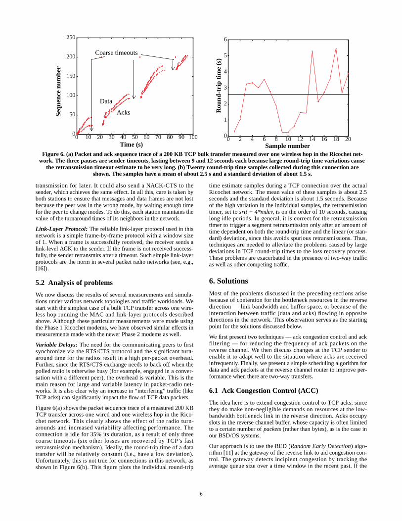
6
transmission for later. It could also send a NACK-CTS to thesender, which achieves the same effect. In all this, care is taken byboth stations to ensure that messages and data frames are not lostbecause the peer was in the wrong mode, by waiting enough timefor the peer to change modes. To do this, each station maintains thevalue of the turnaround times of its neighbors in the network.
Link-Layer Protocol: The reliable link-layer protocol used in thisnetwork is a simple frame-by-frame protocol with a window sizeof 1. When a frame is successfully received, the receiver sends alink-level ACK to the sender. If the frame is not received success-fully, the sender retransmits after a timeout. Such simple link-layerprotocols are the norm in several packet radio networks (see, e.g.,[16]).
5.2 Analysis of problems
We now discuss the results of several measurements and simula-tions under various network topologies and traffic workloads. Westart with the simplest case of a bulk TCP transfer across one wire-less hop running the MAC and link-layer protocols describedabove. Although these particular measurements were made usingthe Phase 1 Ricochet modems, we have observed similar effects inmeasurements made with the newer Phase 2 modems as well.
Variable Delays: The need for the communicating peers to firstsynchronize via the RTS/CTS protocol and the significant turn-around time for the radios result in a high per-packet overhead.Further, since the RTS/CTS exchange needs to back off when thepolled radio is otherwise busy (for example, engaged in a conver-sation with a different peer), the overhead is variable. This is themain reason for large and variable latency in packet-radio net-works. It is also clear why an increase in “interfering” traffic (likeTCP acks) can significantly impact the flow of TCP data packets.
Figure 6(a) shows the packet sequence trace of a measured 200 KBTCP transfer across one wired and one wireless hop in the Rico-chet network. This clearly shows the effect of the radio turn-arounds and increased variability affecting performance. Theconnection is idle for 35% its duration, as a result of only threecoarse timeouts (six other losses are recovered by TCP’s fastretransmission mechanism). Ideally, the round-trip time of a datatransfer will be relatively constant (i.e., have a low deviation).Unfortunately, this is not true for connections in this network, asshown in Figure 6(b). This figure plots the individual round-trip
time estimate samples during a TCP connection over the actualRicochet network. The mean value of these samples is about 2.5seconds and the standard deviation is about 1.5 seconds. Becauseof the high variation in the individual samples, the retransmissiontimer, set to srtt + 4*mdev, is on the order of 10 seconds, causinglong idle periods. In general, it is correct for the retransmissiontimer to trigger a segment retransmission only after an amount oftime dependent on both the round-trip time and the linear (or stan-dard) deviation, since this avoids spurious retransmissions. Thus,techniques are needed to alleviate the problems caused by largedeviations in TCP round-trip times to the loss recovery process.These problems are exacerbated in the presence of two-way trafficas well as other competing traffic.
6. Solutions
Most of the problems discussed in the preceding sections arisebecause of contention for the bottleneck resources in the reversedirection — link bandwidth and buffer space, or because of theinteraction between traffic (data and acks) flowing in oppositedirections in the network. This observation serves as the startingpoint for the solutions discussed below.
We first present two techniques — ack congestion control and ackfiltering — for reducing the frequency of ack packets on thereverse channel. We then discuss changes at the TCP sender toenable it to adapt well to the situation where acks are receivedinfrequently. Finally, we present a simple scheduling algorithm fordata and ack packets at the reverse channel router to improve per-formance when there are two-way transfers.
6.1 Ack Congestion Control (ACC)
The idea here is to extend congestion control to TCP acks, sincethey do make non-negligible demands on resources at the low-bandwidth bottleneck link in the reverse direction. Acks occupyslots in the reverse channel buffer, whose capacity is often limitedto a certain number of packets (rather than bytes), as is the case inour BSD/OS systems.
Our approach is to use the RED (Random Early Detection) algo-rithm [11] at the gateway of the reverse link to aid congestion con-trol. The gateway detects incipient congestion by tracking theaverage queue size over a time window in the recent past. If the
0
50
100
150
200
250
0 10 20 30 40 50 60 70 80 90 100Time (s)
Sequ
ence
num
ber
Figure 6. (a) Packet and ack sequence trace of a 200 KB TCP bulk transfer measured over one wireless hop in the Ricochet net-work. The three pauses are sender timeouts, lasting between 9 and 12 seconds each because large round-trip time variations cause
the retransmission timeout estimate to be very long. (b) Twenty round-trip time samples collected during this connection areshown. The samples have a mean of about 2.5 s and a standard deviation of about 1.5 s.
Coarse timeouts
Data
Acks
0
1
2
3
4
5
6
0 2 4 6 8 10 12 14 16 18 20Sample number
Rou
nd-t
rip
tim
e (s
)
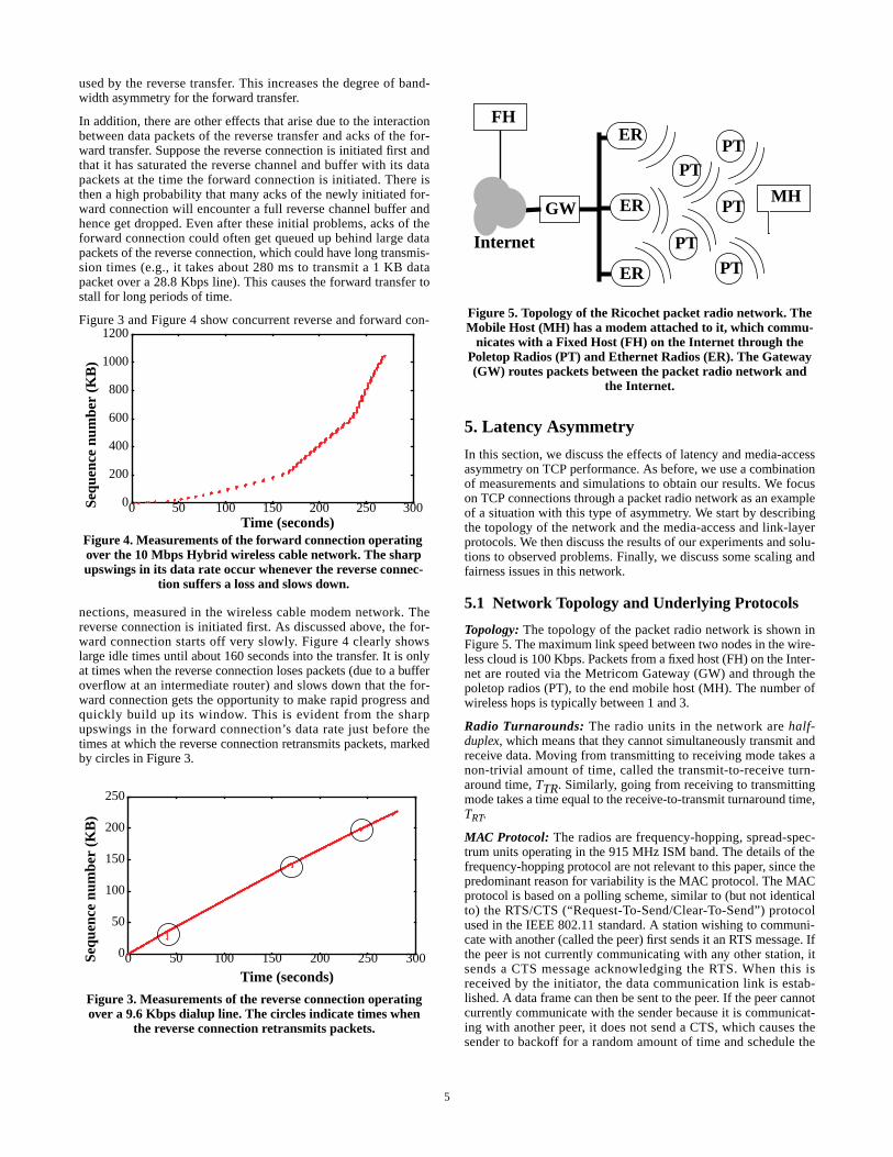
5
used by the reverse transfer. This increases the degree of band-width asymmetry for the forward transfer.
In addition, there are other effects that arise due to the interactionbetween data packets of the reverse transfer and acks of the for-ward transfer. Suppose the reverse connection is initiated first andthat it has saturated the reverse channel and buffer with its datapackets at the time the forward connection is initiated. There isthen a high probability that many acks of the newly initiated for-ward connection will encounter a full reverse channel buffer andhence get dropped. Even after these initial problems, acks of theforward connection could often get queued up behind large datapackets of the reverse connection, which could have long transmis-sion times (e.g., it takes about 280 ms to transmit a 1 KB datapacket over a 28.8 Kbps line). This causes the forward transfer tostall for long periods of time.
Figure 3 and Figure 4 show concurrent reverse and forward con-
nections, measured in the wireless cable modem network. Thereverse connection is initiated first. As discussed above, the for-ward connection starts off very slowly. Figure 4 clearly showslarge idle times until about 160 seconds into the transfer. It is onlyat times when the reverse connection loses packets (due to a bufferoverflow at an intermediate router) and slows down that the for-ward connection gets the opportunity to make rapid progress andquickly build up its window. This is evident from the sharpupswings in the forward connection’s data rate just before thetimes at which the reverse connection retransmits packets, markedby circles in Figure 3.
5. Latency Asymmetry
In this section, we discuss the effects of latency and media-accessasymmetry on TCP performance. As before, we use a combinationof measurements and simulations to obtain our results. We focuson TCP connections through a packet radio network as an exampleof a situation with this type of asymmetry. We start by describingthe topology of the network and the media-access and link-layerprotocols. We then discuss the results of our experiments and solu-tions to observed problems. Finally, we discuss some scaling andfairness issues in this network.
5.1 Network Topology and Underlying Protocols
Topology: The topology of the packet radio network is shown inFigure 5. The maximum link speed between two nodes in the wire-less cloud is 100 Kbps. Packets from a fixed host (FH) on the Inter-net are routed via the Metricom Gateway (GW) and through thepoletop radios (PT), to the end mobile host (MH). The number ofwireless hops is typically between 1 and 3.
Radio Turnarounds: The radio units in the network are half-duplex, which means that they cannot simultaneously transmit andreceive data. Moving from transmitting to receiving mode takes anon-trivial amount of time, called the transmit-to-receive turn-around time, TTR. Similarly, going from receiving to transmittingmode takes a time equal to the receive-to-transmit turnaround time,TRT.
MAC Protocol: The radios are frequency-hopping, spread-spec-trum units operating in the 915 MHz ISM band. The details of thefrequency-hopping protocol are not relevant to this paper, since thepredominant reason for variability is the MAC protocol. The MACprotocol is based on a polling scheme, similar to (but not identicalto) the RTS/CTS (“Request-To-Send/Clear-To-Send”) protocolused in the IEEE 802.11 standard. A station wishing to communi-cate with another (called the peer) first sends it an RTS message. Ifthe peer is not currently communicating with any other station, itsends a CTS message acknowledging the RTS. When this isreceived by the initiator, the data communication link is estab-lished. A data frame can then be sent to the peer. If the peer cannotcurrently communicate with the sender because it is communicat-ing with another peer, it does not send a CTS, which causes thesender to backoff for a random amount of time and schedule the
Figure 3. Measurements of the reverse connection operatingover a 9.6 Kbps dialup line. The circles indicate times when
the reverse connection retransmits packets.
0
50
100
150
200
250
0 50 100 150 200 250 300
Time (seconds)
Sequ
ence
num
ber
(KB
)
Figure 4. Measurements of the forward connection operatingover the 10 Mbps Hybrid wireless cable network. The sharpupswings in its data rate occur whenever the reverse connec-
tion suffers a loss and slows down.
0
200
400
600
800
1000
1200
0 50 100 150 200 250 300Time (seconds)
Sequ
ence
num
ber
(KB
)
Figure 5. Topology of the Ricochet packet radio network. TheMobile Host (MH) has a modem attached to it, which commu-
nicates with a Fixed Host (FH) on the Internet through thePoletop Radios (PT) and Ethernet Radios (ER). The Gateway(GW) routes packets between the packet radio network and
the Internet.
GW
Internet
MH
ER
ER
ER
FH
PTPT
PTPT
PT

4
reverse channel is much slower, for instance a 28.8 Kbps dialupphone line. In our experiments, we also considered an Ethernetreverse channel. While such a configuration is possibly unrealistic,it serves as a useful data point for comparison. In the followingsub-sections, we discuss several performance problems that weobserved based on experiments conducted in the real testbed aswell as in the simulator.
4.2 Analysis of performance problems
We now discuss the problems that arise due the limited bandwidthof the reverse channel in an asymmetric-bandwidth network.
4.2.1 One-way Transfers
We first discuss the case where TCP transfers happen only in theforward direction. A common example of this is a user download-ing data from a server. For simplicity, we initially restrict ourselvesto the case of a single TCP transfer in the forward direction.
We define the normalized bandwidth ratio, k, (as defined in [12])between the forward and reverse paths as the ratio of the raw band-widths divided by the ratio of the packet sizes used in the twodirections. For example, for a 10 Mbps forward channel and a 100Kbps reverse channel, the raw bandwidth ratio is 100. With 1000-byte data packets and 40-byte acks, the ratio of the packet sizes is25. So, k is 100/25 = 4. This implies that if there is more than oneack for every k = 4 data packets, the reverse bottleneck link will getsaturated before the forward bottleneck link does, possibly limitingthe throughput that can be achieved in the forward direction.
The main effect of bandwidth asymmetry in this case is that TCPack clocking can break down. Consider two data packets transmit-ted by the sender in quick succession. While in transit to thereceiver, these packets get spaced apart according to the bottlenecklink bandwidth in the forward direction. The principle of ackclocking is that the acks generated in response to these packetspreserve this spacing (in time) all the way back to the sender,enabling the sender to clock out new data packets with the samespacing.
However, the limited reverse bandwidth and consequent queuingeffects could alter the inter-ack spacing. When acks arrive at thebottleneck link in the reverse direction at a faster rate than the linkcan support (which happens when k > 1 assuming every datapacket is acknowledged), they get queued behind one another. Thespacing between them when they emerge from the link is dilatedwith respect to their original spacing. (This is in contrast to ackcompression which happens when acks get queued at a fast link,i.e. k < 1.) Thus the sender clocks out new data at a slower ratethan if there had been no queuing of acks. Furthermore, thesender’s window growth is slowed down.
This is part of the reason why the measured throughput for a dialupreverse channel without SLIP header compression (Figure 2) is solow. SLIP header compression (CSLIP) reduces the sizes of acksand decreases k, improving performance. For example, considerthe case of a 10 Mbps forward and 28.8 Kbps reverse channel, witha data packet size of 1 KB. With the TCP timestamp optionenabled, the ack size is 52 bytes with SLIP and 18 bytes withCSLIP. So k is 18.05 with SLIP and is 6.25 with CSLIP. With TCPdelayed acks (one ack for every two data packets), throughput islimited to 10*2/18.05 = 1.1 Mbps and 10*2/6.25 = 3.2 Mbps, withSLIP and CSLIP respectively. These numbers closely match themeasured throughputs shown in Figure 2.
In comparison, the performance with an Ethernet return channel ismuch better because of the absence of bandwidth asymmetry (k is0.052) and a much smaller link delay than the dialup lines. As anaside, the throughput shows a dip beyond a socket buffer size of 16KB because larger socket buffer sizes lead to overflow of somerouter queue along the forward path.
In practice, the reverse bottleneck link will also have a finiteamount of buffer space. If the TCP transfer lasts long enough, thisbuffer can fill up and cause acks to get dropped. If the receiveracknowledges every packet, on average (k-1) out of every k acksget dropped at the reverse channel buffer. Since in effect only oneack traverses the reverse bottleneck link for every k data packets,acks may not directly limit forward throughput. However, this situ-ation leads to several other problems because the sender nowreceives fewer acks than it would have otherwise.
First, the sender could become bursty. If the sender receives onlyone ack in k, it ends up sending out data in bursts of k packets. Thisincreases the chance of data packet loss, especially when k is large.Second, since conventional TCP senders base their windowincrease on counting the number of acks and not on how muchactual data is acknowledged, fewer acks imply a slower rate ofgrowth of the congestion window. Third, the receipt of fewer ackscould disrupt the sender’s fast retransmission algorithm when thereis a data packet loss. The sender may not receive the thresholdnumber of duplicate acks although the receiver may have sent outmore than the required number. And finally, the loss of the (nowinfrequent) acks further down the path to the sender could causelong idle periods while the sender waits for subsequent acks toarrive.
4.2.2 Two-way Transfers
We now consider the case when TCP transfers simultaneouslyoccur in the forward and reverse directions. An example of this is auser sending out data (for example, an e-mail message) whilesimultaneously receiving other data (for example, Web pages). Werestrict our discussion to the case of one connection in each direc-tion.
In this scenario, the effects discussed in Section 4.2.1 are morepronounced, because some of the reverse direction bandwidth is
0
1
2
3
4
5
6
0 20 40 60 80 100 120 140 160 180 20
Figure 2. Measured performance of the Hybrid wireless cablenetwork using different return channels, across a range of
socket buffer sizes. Each run of the experiment involved thetransfer of 1 MB of data in the forward direction between
two BSD/OS hosts.
Socket buffer size (KBytes)
Thr
ough
put
(Mbp
s) 10 Mbps Ethernet
28.8 Kbps SLIP
28.8 Kbps CSLIP
9.6 Kbps CSLIP9.6 Kbps SLIP

3
topology for this network is shown in Figure 5. The packetradios operate in the 915 MHz ISM band and have a raw linkspeed of 100 Kbps. The poletop units typically have a range ofseveral hundred meters.
The wireless cable modem testbed is an example of a network withbandwidth asymmetry depending on the return path used, whichcould be a dialup phone line (e.g., 14.4 Kbps or 28.8 Kbps), or awireless channel. In a good installation of the wireless cablemodem network, the bit-error rate of the forward channel is negli-gible. We therefore do not focus on the effects of bit-errors on theforward channel in this paper.
The packet radio network we study is an example of a network thatdoes not have explicit (bandwidth) asymmetry, but has the charac-teristic that the flow of traffic (e.g., TCP data) in one direction isaffected by the flow of traffic (e.g., TCP acks) in the oppositedirection. This arises because of the half-duplex nature of the radiounits that cannot simultaneously send and receive packets, havingto incur a significant overhead in turning around from one mode tothe other.
After studying the impact of each type of asymmetry indepen-dently, we combine networks with these different asymmetriccharacteristics and study the performance characteristics of TCPconnections through them. We now describe the details of our sim-ulation setup, workloads, and performance metrics.
3.2 Simulation Setup and Performance Metrics
We used ns [20], an event-driven packet-level network simulatorfrom Berkeley and LBNL for our work. We developed severalextensions to this simulator to model the networks of interest to us.We added the notion of a shared link (LAN) to the simulator withthe ability to incorporate arbitrary link-layer and media-accessprotocols. Our simulations of the packet radio network use a MACprotocol loosely based on Ricochet’s protocol. The details of theseadditions are described in Section 5.1.
Our simulation parameters (such as link bandwidth, latency, andpacket-radio turn-around time) and topologies are derived from thecharacteristics of the networks in our experimental testbed. We
validated the simulated performance of standard TCP and con-stant-rate UDP traffic with actual measurements in the real net-works. We experiment with two kinds of workloads — large bulktransfers and short Web-like transfers. We also consider simulta-neous transfers in opposite directions.
Our main performance metrics are throughput measured at thereceiver and a metric for fairness, called the fairness index [8]. Thefairness index, f, is defined as follows: if there are n concurrentconnections in the network and the throughput achieved by con-nection i is equal to xi, 1 <= i <= n, then
The fairness index always lies between 0 and 1 (since throughputis non-negative), and as explained in [14], is equal to (k /n) if k ofthe n connections receive equal throughput and the remainingnone. Thus, f cannot be less than 1/n in a network with n connec-tions. We use the fairness index to understand and analyze the scal-ing properties of the network when multiple connections aresimultaneously active.
4. Bandwidth Asymmetry
In this section, we discuss the network topology and performanceproblems that arise due to bandwidth asymmetry. These includethe slowdown and increased burstiness of a TCP sender due to thedisruption of ack clocking, and highly variable performance whenthere are simultaneous TCP transfers in both the forward and thereverse directions.
4.1 Network Topology
The network topology of the wireless cable system is shown inFigure 1. The bandwidth of the forward channel is 10 Mbps. The
f
xii 1=
n
∑ 2
n xi2
i 1=
n
∑---------------------
˙
=
Figure 1. The network topology of the wireless cable modem network which illustrates bandwidth asymmetry. Hosts on the clientsubnet receive data from the Internet via the 10 Mbps wireless cable link (the forward channel) and send out data via a low band-
width (e.g., dialup) link (the reverse channel).
Internet
Wireless Transmitter
Internet Server
Client subnet
Modem
Relay Tower
Ethernet
Dialup Line

2
relying on the timely arrival of acknowledgments, to make steadyprogress and fully utilize the available bandwidth of the path [12].Thus, any disruption in the feedback process could potentiallyimpair the performance of the forward data transfer. For example,a low bandwidth acknowledgment path could significantly slowdown the growth of the TCP sender window during slow start,independent of the link bandwidth in the direction of data transfer.A second example is from packet radio networks, where variablelatencies in the presence of bidirectional traffic (caused, forinstance, by acknowledgements flowing in a direction opposite todata packets) causes the sender’s round-trip time estimate to behighly variable. This inflates TCP’s retransmission timeout value,thereby impairing loss recovery.
The following are our major results and conclusions:
• SLIP header compression [13] alleviates some of the perfor-mance problems due to bandwidth asymmetry, but does notcompletely eliminate all problems, especially those that arisein the presence of bidirectional traffic.
• Connections traversing packet radio networks suffer from largevariations in round-trip time caused by the half-duplex natureof the radios and asymmetries in the media-access protocol.This adversely affects TCP’s loss recovery mechanism andresults in degraded performance.
• The various end-to-end and router-based techniques that wepropose help improve performance significantly in manyasymmetric situations, both in simulations and in experimentson the real testbed. These include decreasing the frequency ofacknowledgments (acks) on the constrained reverse channel(ack congestion control and ack filtering), reducing sourceburstiness when acknowledgments are infrequent (TCP senderadaptation), and scheduling data and acks intelligently at thereverse bottleneck router.
• In addition to improving throughput for individual connec-tions, our proposed modifications also help improve the fair-ness and scaling properties when several connections contendfor scarce resources in the network. We demonstrate this viasimulations of bulk and Web-like transfers.
The rest of the paper is organized as follows. Section 2 describessome related work and Section 3 discusses the details of our exper-imental testbed and methodology. We then analyze the problemsthat arise due to bandwidth asymmetry (Section 4) and latency/media-access asymmetry (Section 5) using measurements andpacket traces from our network testbed. In Section 6, we presentseveral end-to-end and router-based techniques to alleviate theproblems due to asymmetry. An evaluation of these techniques viasimulation appears in Section 7. We implemented the techniquesthat seemed promising based on the simulation experiments, in ourtestbed. The implementation is described in Section 8, and a per-formance evaluation of the implementation, that confirms thetrends observed in simulation, is presented in Section 9. Wepresent our conclusions in Section 10 and plans for future work inSection 11.
2. Related Work
Several researchers have identified and proposed solutions to trans-port protocol problems that arise in single-hop wireless networks[1, 3, 4, 6]. The main issue considered in these papers is the impactof packet losses due to reasons other than congestion (wirelesserror, handoff, etc.) on TCP performance. We view our work asbeing in the natural progression of such research, with the overallgoal of understanding and improving the performance of reliabletransport protocols like TCP in the face of ever-increasing hetero-
geneity in network technologies and characteristics. The specificmeasurements reported in this paper were taken over a wirelesscable modem network and a packet radio network.
There has been some previous work on understanding the effectsof two-way traffic on TCP performance. In [24], the authors dem-onstrate how two-way traffic can lead to ack compression, whereclosely-bunched acknowledgments disrupt the smooth ack-clockedtransmission at the sender. More recently, there has been interest inhow asymmetric-bandwidth networks exacerbate this problem. In[18], the authors model a network with bandwidth asymmetry andderive analytical expressions for throughput in terms of packet lossprobability and the normalized asymmetry ratio under certain idealassumptions. They also propose the use of a drop-from-front strat-egy for dropping acknowledgments at the bandwidth-constrainedreverse link. In [15], the authors demonstrate how bidirectionaltraffic over asymmetric links leads to ack compression, and conse-quently, degraded performance. They investigate a backpressuremechanism to limit data flow in the reverse direction, but concludethat this alone is not enough for good performance.
There have also been studies of bandwidth asymmetry in the con-text of satellite networks [9, 22]. The main distinction betweensuch a network and the wireless cable modem network we considerin this study is that the former has a much larger bandwidth-delayproduct, which could be the dominating factor in performance.Finally, some basic performance measurements of Metricom’sRicochet packet radio network are presented in [7].
While the results and analysis in [15] and [18] are very useful, theset of problems is far from being understood or solved. In additionto proposing and evaluating other schemes to alleviate the adverseeffects of bandwidth asymmetry, we also characterize other typesof asymmetry that occur in wide-area wireless networks. We eval-uate our solutions for these networks in terms of connectionthroughput, fairness, and scaling behavior.
3. Experimental and Simulation Methodology
In this section, we describe our experimental testbed, simulationsetup, and traffic workloads used in the study.
3.1 Experimental Testbed
We use a combination of simulation and actual experimentation ona heterogeneous network testbed to evaluate the performance ofTCP, understand the reasons for observed performance, and designend-host and router-based techniques to improve performance. Oursimulation topologies and parameters are derived from the follow-ing networks in our testbed:
• Wireless cable modem network: This is a wireless cablemodem network using technology developed by Hybrid Net-works, Inc. (www.hybrid.com). The aggregate bandwidth of the(unidirectional) forward channel is 10 Mbps4 and the one-waylink latency is about 5ms. The topology for this testbed isshown in Figure 1. The downstream channel for data operatesin the 2.4 GHz range and is down-converted at the receivingend to standard television channel frequencies. The reversechannel could be a dialup line, an ISDN line, a wireless chan-nel using a wide-area packet radio network, etc.
• Packet radio network: Our packet radio network is based onMetricom Inc.’s Ricochet network (www.metricom.com). The
4. A 30 Mbps 2-way wireless cable system is currently underdevelopment; this system also exhibits bandwidth asymmetry.
1
The Effects of Asymmetry on TCP Performance1
Hari Balakrishnan2, Venkata N. Padmanabhan3, and Randy H. Katz
Abstract
In this paper, we study the effects of network asymmetry on end-to-end TCP performance and suggest techniques to improve it. Thenetworks investigated in this study include a wireless cable modemnetwork and a packet radio network, both of which can form animportant part of a mobile ad hoc network. In recent literature(e.g., [18]), asymmetry has been considered in terms of a mis-match in bandwidths in the two directions of a data transfer. Wegeneralize this notion of bandwidth asymmetry to other aspects ofasymmetry, such as latency and media-access, and packet errorrate, which are common in wide-area wireless networks.
Using a combination of experiments on real networks and simula-tion, we analyze TCP performance in such networks where thethroughput achieved is not solely a function of the link and trafficcharacteristics in the direction of data transfer (the forward direc-tion), but depends significantly on the reverse direction as well. Wefocus on bandwidth and latency asymmetries, and propose andevaluate several techniques to improve end-to-end performance.These include techniques to decrease the rate of acknowledgmentson the constrained reverse channel (ack congestion control and ackfiltering), techniques to reduce source burstiness when acknowl-edgments are infrequent (TCP sender adaptation), and algorithmsat the reverse bottleneck router to schedule data and acks differ-ently from FIFO (acks-first scheduling).
Keywords: TCP, asymmetry, cable modem, wireless networks
1. Introduction
The Transmission Control Protocol (TCP) is widely used in theInternet for reliable, unicast communications. The robustness ofTCP in a wide variety of networking environments is the primaryreason for its widespread usage. However, emerging networkingtechnologies pose new challenges to TCP in terms of performance,which motivate the development of new TCP algorithms. In thispaper, we focus on the challenges to end-to-end TCP performancethat arise due to network asymmetry, including in the context ofwide-area wireless networks. The increased interest in asymmetricnetworks is motivated by technological and economic consider-ations as well as by the popularity of applications such as Webaccess, which involve a substantially larger data flow towards theclient (the forward direction) than from it (the reverse direction).
Examples of networks that exhibit asymmetry include cablemodem networks (both wireline and wireless), direct broadcastsatellite networks, and Asymmetric Digital Subscriber Loop(ADSL) networks, where bandwidth in the forward direction is
1. A more detailed treatment of the material in this paper appearsin the theses [2] and [21].2. Presently at MIT’s Lab for Computer Science and EECS Dept.3. Presently at Microsoft Research.
often orders of magnitude larger than that in the reverse. Suchasymmetry is accentuated when the channel is unidirectional,necessitating the use of a different, often low-bandwidth channel(e.g., a dialup line or a bandwidth-constrained and lossy wirelesschannel) for communication in the reverse direction.
Our study is not limited to networks where the asymmetry isexplicit because of mismatched bandwidths — we also study TCPdynamics in packet radio networks, where traffic flowing simulta-neously in different directions can adversely affect performance.This is because most packet radio networks use half-duplex radiounits, which cannot transmit and receive data frames at the sametime. In addition, we combine two wireless technologies — wire-less cable and packet radio — in our study to understand the prob-lems that arise in these situations when different types ofasymmetry are tied together.
Asymmetry is inherent in several wireless networks, where it isoften the case that a central transmitter (or base station) can trans-mit at high power to receiving portable/mobile units. However, toreduce power consumption, these units transmit to the base stationat relatively low power. In addition, they often have to contendwith other mobile units to gain access to the channel.
Such asymmetric networks are often used in mobile ad hoc envi-ronments. As an example, consider a detachment of soldiers in thebattlefield who communicate with each other via a packet radionetwork (which exhibits latency/media-access asymmetry) andwhose link to the outside world is via an asymmetric-bandwidthsatellite or wireless cable modem network. A TCP connectionbetween an one of the mobile nodes (e.g., a soldier’s computer)and a host in the wired Internet (e.g., a database server at the com-mand center) will have to contend with both forms of asymmetry.Thus, it is important to consider the aspect of asymmetry whileanalyzing TCP performance in mobile ad hoc networks.
We generalize the various phenomena and examples describedabove to the following definition of asymmetry: a network is saidto exhibit network asymmetry with respect to TCP performance, ifthe throughput achieved is not solely a function of the link andtraffic characteristics of the forward direction, but depends signifi-cantly on those of the reverse direction as well. In addition to thebandwidth asymmetry described above, this definition extends toother types of asymmetry, such as latency and media-access, andpacket error rate. In this paper, we study bandwidth, and latencyand media-access asymmetries, both individually and in combina-tion. We use measurements on a real testbed as well as simulationsexperiments with different choices of topology and workload, toidentify the performance problems. Based on these results, we pro-pose and evaluate several techniques to improve performance. Thewireless networks that serve as the basis for our work include awireless cable modem network and a packet radio network.
Fundamentally, network asymmetry affects the performance ofreliable transport protocols such as TCP because these protocolsrely on feedback in the form of cumulative acknowledgments fromthe receiver to ensure reliability. In addition, TCP is ack-clocked,
{hari,padmanab,randy}@cs.berkeley.eduComputer Science Division, Department of EECS
University of California at Berkeley, Berkeley, CA 94720-1776.