author, aalto behavioral laboratory introduction to eeg
TRANSCRIPT
Aalto Behavioral Laboratory
Author, date: Veli-Matti Saarinen, 31.10.2017
Introduction to EEG system
1/15
'Aalto University Postal Address Street Address Contacts School of Science P.O. BOX 13000 Otakaari 5 I +358 (0)50 4371613 Aalto Behavioral Laboratory 00076 AALTO Espoo [email protected]
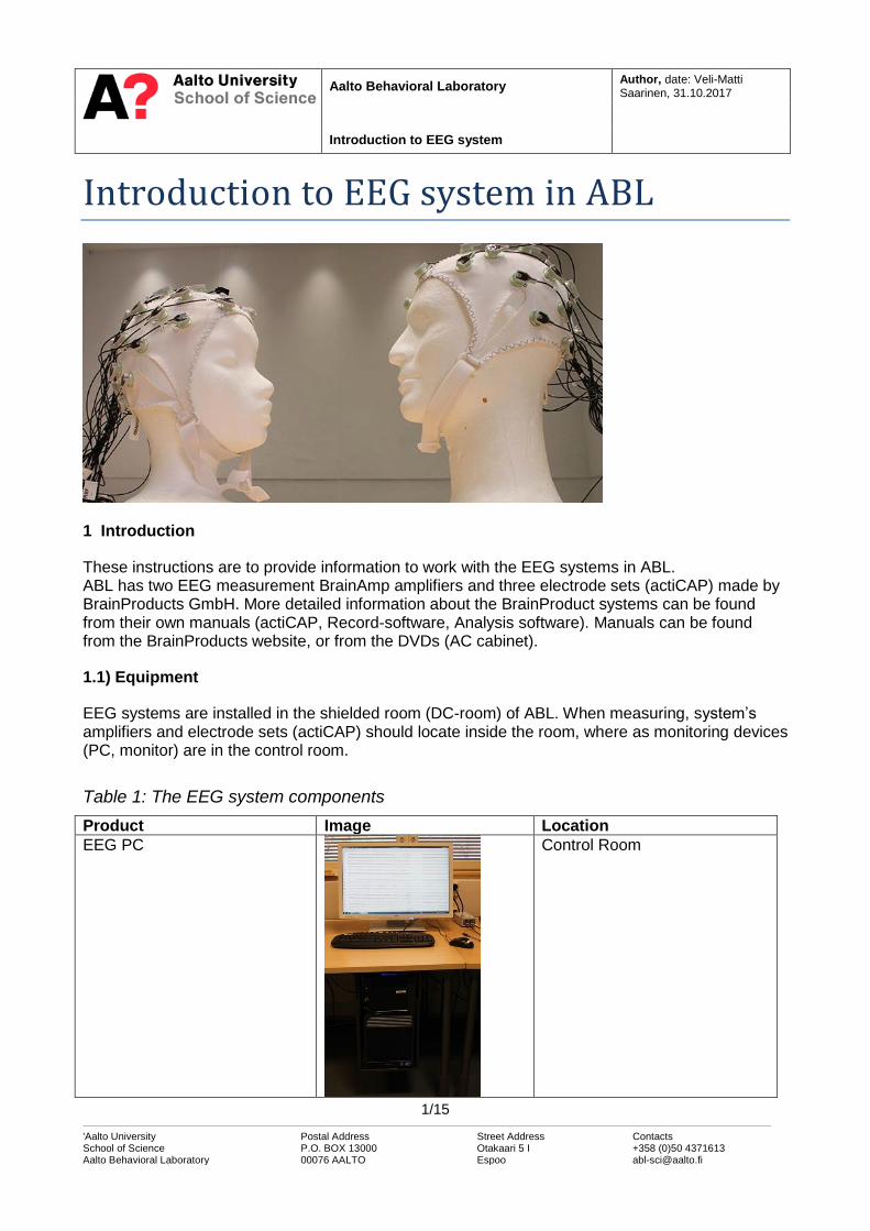
Introduction to EEG system in ABL
1 Introduction
These instructions are to provide information to work with the EEG systems in ABL. ABL has two EEG measurement BrainAmp amplifiers and three electrode sets (actiCAP) made by BrainProducts GmbH. More detailed information about the BrainProduct systems can be found from their own manuals (actiCAP, Record-software, Analysis software). Manuals can be found from the BrainProducts website, or from the DVDs (AC cabinet).
1.1) Equipment
EEG systems are installed in the shielded room (DC-room) of ABL. When measuring, system’s amplifiers and electrode sets (actiCAP) should locate inside the room, where as monitoring devices (PC, monitor) are in the control room.
Table 1: The EEG system components
Product Image Location
EEG PC
Control Room

Aalto Behavioral Laboratory
Operation Instruction EEG System
2/15
'Aalto University Postal Address Street Address Contacts School of Science P.O. BOX 13000 Otakaari 5 I +358 (0)50 4371613 Aalto Behavioral Laboratory 00076 AALTO Espoo [email protected]
actiCAP electrode set (x3)
aEB09011749 (1) aEB16065002 (2) aEB16105372 (3)
Control Room, DC shelves
EEG cap (x6) Sizes:
54, 56, 56, 58, 58, 60 32ch
58 64ch
Control Room, DC shelves Control Room, AC cabinet
Control Box (x2)
aCAP08091276 (1) aCAP10101472 (2)
Control Room, DC shelves
BrainAmp + PowerPack (x2)
Amp0202049 (1) Amp0202044 (2) PP1003642 (1) PP1003641 (2)
DC, Feedthrough cabin
USB2Adapter
BUA128-1002152
Control Room, DC monitor ta-ble
Parallel Box and EEG Input Box
Control Room, DC Shelves
1.2) Consumer products and cleaning items
Consumer products like gels, syringes and nets, which you need in preparation of the subject, can be found from the AC cabinet. Cleaning equipment can be found from the Sink cabinet.

Aalto Behavioral Laboratory
Operation Instruction EEG System
3/15
'Aalto University Postal Address Street Address Contacts School of Science P.O. BOX 13000 Otakaari 5 I +358 (0)50 4371613 Aalto Behavioral Laboratory 00076 AALTO Espoo [email protected]
Product Description / Location
Syringes (5ml, 10ml) AC cabinet
Needles AC cabinet
Gel AC cabinet
Net AC cabinet
Toothbrush Sink cabinet
Detergent Sink cabinet
Towels Sink cabinet
There are also some miscellaneous stuff in AC cabinet, such as tapes, extra electrodes, etc.. If some of these consumer products are running low, please contact personnel.
1.3) Wiring
The wiring of the installed EEG systems is described in the figure below.
Image 1: Wiring of the EEG systems in ABL The setup in the control room is a permanent installation and shouldn’t be altered. Still, always check before measurements that everything is correct. The following should be connected.
1) USB adapter attached to EEG PC via USB cable 2) Parallel EEG box attached to USB-adapter 3) Optic fiber attached to USB-adapter 4) Green license dongle (Recorder software) attached to EEG PC

Aalto Behavioral Laboratory
Operation Instruction EEG System
4/15
'Aalto University Postal Address Street Address Contacts School of Science P.O. BOX 13000 Otakaari 5 I +358 (0)50 4371613 Aalto Behavioral Laboratory 00076 AALTO Espoo [email protected]
When measuring, do also the following:
1) Attach Optic fiber attached to the Amplifier 2) Attach BrainAmp to Control Box via ribbon cable 3) Attach PowerPack to Amplifier via power cable 4) Turn on Amplifier
Image 2: Left image: Amplifier and PowerPack connected. Right image: Back side of the EEG PC
If you are using two (2) EEG caps simultaneously: repeat the last 1-3 phases.
1.4) Electrically shielded room
DC-room is an electrically shielded room; it serves as a Faraday cage, reducing external electric and radio frequency interference in EEG measurements. The cage is made out of galvanized steel.
Keep the door closed when conducting EEG measurements. Read the instruction next to the door on the wall (inside and outside) about how to open can close the door. In emergency, when the door is stuck, use the emergency opener (instructions on the wall).
Aalto Behavioral Laboratory
Operation Instruction EEG System
5/15
'Aalto University Postal Address Street Address Contacts School of Science P.O. BOX 13000 Otakaari 5 I +358 (0)50 4371613 Aalto Behavioral Laboratory 00076 AALTO Espoo [email protected]
2 EEG PC
2.1) Recorder Software
Start the recorder software by clicking the “BrainVision Recorder”. The software dongle (green) needs to be connected to the PC before running the Recorder software. You can also use Recorder software with actiCAP Control software, where you can modify the set-tings of the actiCAP easily. Notice that when using an actiCAP Control software, the control box needs to be connected via USB-cable to EEG PC (remove the batteries first). This software is meant for recording only, and doesn’t include any analysis features.
2.1.1 Creating workspace
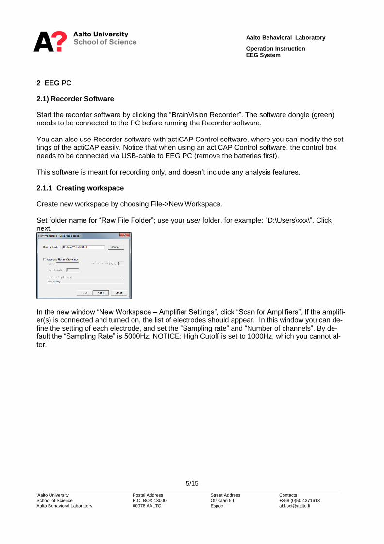
Create new workspace by choosing File->New Workspace. Set folder name for “Raw File Folder”; use your user folder, for example: “D:\Users\xxx\”. Click next.
In the new window “New Workspace – Amplifier Settings”, click “Scan for Amplifiers”. If the amplifi-er(s) is connected and turned on, the list of electrodes should appear. In this window you can de-fine the setting of each electrode, and set the “Sampling rate” and “Number of channels”. By de-fault the “Sampling Rate” is 5000Hz. NOTICE: High Cutoff is set to 1000Hz, which you cannot al-ter.

Aalto Behavioral Laboratory
Operation Instruction EEG System
6/15
'Aalto University Postal Address Street Address Contacts School of Science P.O. BOX 13000 Otakaari 5 I +358 (0)50 4371613 Aalto Behavioral Laboratory 00076 AALTO Espoo [email protected]
In the upcoming windows you can define filters and averaging parameters. When collecting raw data, you don’t necessarily need to define anything. After these, prompts “save as” window, were you can set the name and folder for your workspace file. Use “D:\Data\Vision\Workfiles\” folder. You can edit settings later from File->Edit Workspace.
2.1.2 Recording
After correct workspace is opened:
Press “eye” -icon to monitor the view
Press “play” to start recording o After press, “saving file” menu will prompt. After pressing “save” button, the record-
ing will start immediately.
Press “pause” for pausing
Press “stop” for stop recording
Press “S icon inside red ball”, to stop the monitor view.
Image 3: Setup window
Notice that recording must be ON before you can receive any triggers. You can also annotate the data by clicking “pen” (annotation) during the recording.
3 Stimulus PC
You can synchronize EEG data with the stimulus presentation by sending TTL pulses from the Stimulus PC.

Aalto Behavioral Laboratory
Operation Instruction EEG System
7/15
'Aalto University Postal Address Street Address Contacts School of Science P.O. BOX 13000 Otakaari 5 I +358 (0)50 4371613 Aalto Behavioral Laboratory 00076 AALTO Espoo [email protected]
There are few software (Presentation, ExperimentBuilder, PsychoPy, Matlab) which are already installed in the ABL and can send TTL-triggers. Contact personnel if you want to use some other software.
3.1) Wiring
Parallel port of the Stimulus PC is connected to “Parallel interface box” via ribbon cable and “EEG input” box is connected to EEG PC via Parallel cable. These wiring enables connection between two computers with the BNC cables between the boxes.
Image 4: “BNC – Parallel port” and “EEG Input” boxes are connected with BNC-cables. This will make the connection from Stimulus PC to EEG PC.
Connect the cables to “input” channels of EEG parallel interface box.
3.1.1 Presentation software
The parallel port output box enables of sending TTL pulses. TTL-pulses from the parallel port are automatically seen in the EEG monitor view window, and are stored into *.VMRK –file by default. TTL triggers are sent from Stimulus PC to the Host PC via parallel ports. These triggers/markers are shown directly in the data file.
3.1.1.1 Presentation Settings
In the Presentation, an output port needs to be defined in the port setting menu (Settings/Port). Add new output port (Output Ports->Add). Set the output port as LPT1-port. You can also define the length of the pulse (Default Pulse Width).

Aalto Behavioral Laboratory
Operation Instruction EEG System
8/15
'Aalto University Postal Address Street Address Contacts School of Science P.O. BOX 13000 Otakaari 5 I +358 (0)50 4371613 Aalto Behavioral Laboratory 00076 AALTO Espoo [email protected]
Image 5: Setting the output port, LPT1
Image 6: Setting the LPT1 port
3.1.1.2 Scenario files
In the scenario file, “port_code” should be included inside the trial. The codes are sent at the time the trial is presented (started). You can send numbers between 0-255.
trial { picture { box { height = 10; width = 10; color = 0,0,0; }; # shows a black box x = 0; y = 0; } pic1; port_code = 2; # this code is sent at the time “trial1” is presented }trial1;
For example if you send port_code = 2, you will see S2 in your data:

Aalto Behavioral Laboratory
Operation Instruction EEG System
9/15
'Aalto University Postal Address Street Address Contacts School of Science P.O. BOX 13000 Otakaari 5 I +358 (0)50 4371613 Aalto Behavioral Laboratory 00076 AALTO Espoo [email protected]
Mk5=Stimulus,S 2,5023,1,0 ; Mk=<Type>,<Description>,<Position>, <Size>, <Channel number>
The marker that you see in the EEG-data file is an onset trigger. The number “5023” is number order of data points. So with the sampling rate 1000Hz, this trigger would appear at 5023ms from the start.
Image 7: Marker triggers at the bottom: ”S3, S7, S3 S7”.
3.2) Experiment Builder
The Experiment Builder is a visual experiment creation tool for use with the EyeLink eye tracker made by SR Research. While a primary goal of the Experiment Builder has been to create EyeLink experiments; the Experiment Builder can also be used to create non EyeLink experiments that do not need eye tracking functionality. You can also send TTL-pulses using LPT1 port.
3.3) PsychoPy
http://www.psychopy.org/
3.4) Matlab Psychtoolbox
http://psychtoolbox.org/
4 EEG Preparation
4.1) Subject Preparation
Ask subject to wash their hair at the morning before the EEG.
Avoid drinking coffee or anything else with caffeine, which can affect the results, before measurement.

Aalto Behavioral Laboratory
Operation Instruction EEG System
10/15
'Aalto University Postal Address Street Address Contacts School of Science P.O. BOX 13000 Otakaari 5 I +358 (0)50 4371613 Aalto Behavioral Laboratory 00076 AALTO Espoo [email protected]
Ask subject to remove all electronic devices before entering the shielded room.
4.2) Setting up the system
Get needles, syringes, gel and paper towels ready for measurement and place them on the prepa-ration table of the DC-room. Use “Electrode support cups” to carry the stuff.
Image 8: Electrode support cups including Gel, Syringes, Needles and paper towels
Image 9: Preparation table ready for preparation. ActiCap on the top left, control box in the top middle and amplifier and power pack on the top right. Consumer products for two are in the bottom, including needles, syringes and pack of Gel. Also some paper towels to wipe things. Red measurement tape is on the right.
Connect actiCAP system and amplifier to the control box. Check that both cables refer to same channel numbers (for example ch1-32).
Aalto Behavioral Laboratory
Operation Instruction EEG System
11/15
'Aalto University Postal Address Street Address Contacts School of Science P.O. BOX 13000 Otakaari 5 I +358 (0)50 4371613 Aalto Behavioral Laboratory 00076 AALTO Espoo [email protected]
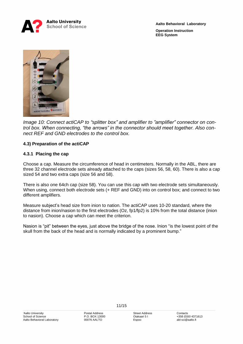
Image 10: Connect actiCAP to “splitter box” and amplifier to ”amplifier” connector on con-trol box. When connecting, “the arrows” in the connector should meet together. Also con-nect REF and GND electrodes to the control box.
4.3) Preparation of the actiCAP
4.3.1 Placing the cap
Choose a cap. Measure the circumference of head in centimeters. Normally in the ABL, there are three 32 channel electrode sets already attached to the caps (sizes 56, 58, 60). There is also a cap sized 54 and two extra caps (size 56 and 58). There is also one 64ch cap (size 58). You can use this cap with two electrode sets simultaneously. When using, connect both electrode sets (+ REF and GND) into on control box; and connect to two different amplifiers. Measure subject’s head size from inion to nation. The actiCAP uses 10-20 standard, where the distance from inion/nasion to the first electrodes (Oz, fp1/fp2) is 10% from the total distance (inion to nasion). Choose a cap which can meet the criterion. Nasion is “pit” between the eyes, just above the bridge of the nose. Inion “is the lowest point of the skull from the back of the head and is normally indicated by a prominent bump.”

Aalto Behavioral Laboratory
Operation Instruction EEG System
12/15
'Aalto University Postal Address Street Address Contacts School of Science P.O. BOX 13000 Otakaari 5 I +358 (0)50 4371613 Aalto Behavioral Laboratory 00076 AALTO Espoo [email protected]
Image 11: Placing the cap according to the 10-20 standard. /Image from “Bioelectromag-netism Principles and Applications of Bioelectric and Biomagnetic Fields, Chapter 13 Elec-troencephalography”/.
Open subject hair (pony tail, plait, etc..) before placing a cap. Place the cap to subject’s head and tighten the strap under the chin. Place all electrodes to the cap (if not already connected). Also remember REF and GND electrodes. Connect the ribbon cable of the actiCAP to the control box. Connect the amplifier to the control box via ribbon cable. Make sure that actiCAP and amplifier refers to same channels (for example 1-32) on control box.
4.3.1.1 Extra electrodes
You can connect extra electrodes (i.e. EOG) via second amplifier. Connect passive electrodes to “Electrode input Box -64channels” box. Connect electrode box directly to amplifier with a ribbon cable. NOTICE: Own REF and GND electrodes are required for this second amplifier. In the re-corder software; choose two amplifiers. Attach the electrodes with two-sided tape on the skin.
Aalto Behavioral Laboratory
Operation Instruction EEG System
13/15
'Aalto University Postal Address Street Address Contacts School of Science P.O. BOX 13000 Otakaari 5 I +358 (0)50 4371613 Aalto Behavioral Laboratory 00076 AALTO Espoo [email protected]
4.3.2 Preparation
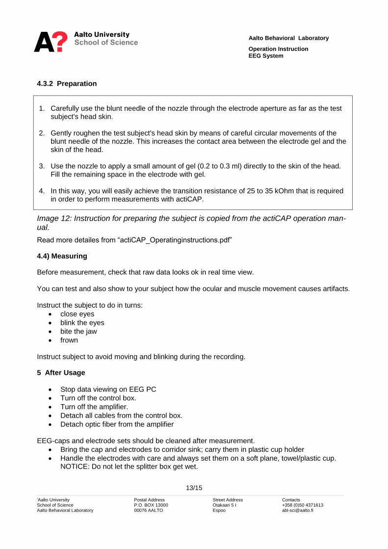
1. Carefully use the blunt needle of the nozzle through the electrode aperture as far as the test
subject's head skin. 2. Gently roughen the test subject's head skin by means of careful circular movements of the
blunt needle of the nozzle. This increases the contact area between the electrode gel and the skin of the head.
3. Use the nozzle to apply a small amount of gel (0.2 to 0.3 ml) directly to the skin of the head.
Fill the remaining space in the electrode with gel. 4. In this way, you will easily achieve the transition resistance of 25 to 35 kOhm that is required
in order to perform measurements with actiCAP.
Image 12: Instruction for preparing the subject is copied from the actiCAP operation man-ual.
Read more detailes from “actiCAP_Operatinginstructions.pdf”
4.4) Measuring
Before measurement, check that raw data looks ok in real time view. You can test and also show to your subject how the ocular and muscle movement causes artifacts. Instruct the subject to do in turns:
close eyes
blink the eyes
bite the jaw
frown Instruct subject to avoid moving and blinking during the recording.
5 After Usage
Stop data viewing on EEG PC
Turn off the control box.
Turn off the amplifier.
Detach all cables from the control box.
Detach optic fiber from the amplifier EEG-caps and electrode sets should be cleaned after measurement.
Bring the cap and electrodes to corridor sink; carry them in plastic cup holder
Handle the electrodes with care and always set them on a soft plane, towel/plastic cup. NOTICE: Do not let the splitter box get wet.

Aalto Behavioral Laboratory
Operation Instruction EEG System
14/15
'Aalto University Postal Address Street Address Contacts School of Science P.O. BOX 13000 Otakaari 5 I +358 (0)50 4371613 Aalto Behavioral Laboratory 00076 AALTO Espoo [email protected]
Remove the electrodes from their holders and put them in a plastic cup. Clean the elec-trodes and cap with few drops of “Ivory” shampoo (on sink cabinet) and a toothbrush. Rinse the electrodes under lukewarm running water and wrap them in a towel for 10 minutes.
Hang the caps and electrodes to dry. See more detailed instructions about handling the caps from “actiCAP Operating Instructions, Chapter 8: Cleaning the electrodes and cap”.
6 PowerPack
PowerPack locates in the storage room, where they are always connected to power supply.
After the use, please return the battery to its place, and connect it to a charger.
7 EEG artifacts
There are several sources that can induce noise artifacts. Most common ones are: Physiologic Artifacts
Muscle activity: Temporalis muscles are common causes.
Glossokinetic artifact: Tongue functions as dipole
Eye Movements: Generates a large-amplitude alternate current field
ECG artifact: rhythmic/regular
Pulse: When an EEG electrode is placed over a pulsating vessel
Respiration artifacts: Slow and rhythmic activity
Skin artifacts: Sweating (due to heat or stress) may produce huge slow baseline sways. Extraphysiologic Artifacts
Electrodes popping: Sharp waveforms
Alternating current artefact (50Hz)
Movements of other persons
In general, instruct your subject to avoid extra movement during the measurement. Make sure that the subject is feeling comfortably (not too hot, no stress).

Aalto Behavioral Laboratory
Operation Instruction EEG System
15/15
'Aalto University Postal Address Street Address Contacts School of Science P.O. BOX 13000 Otakaari 5 I +358 (0)50 4371613 Aalto Behavioral Laboratory 00076 AALTO Espoo [email protected]
8 Analysis
8.1) Data formats
Recorder software will produce three files for each recording:
.eeg –file, eeg-data
.vhdr –file, header file and channel information
.vmrk –file, marker information Files will be located on “Raw File Folder”, which you have set in the workspace.
8.2) Software
8.2.1 Analyser 2
Analyser 2 is versatile analysis software for EEG-data, made by BrainProducts. Analyser 2 is in-stalled in ANI analysis corner. License dongle (EEG) needs to be connected when using the soft-ware. http://www.brainproducts.com/promo_analyzer2.php
8.2.2 EEG-Lab
EEG-Lab is a Matlab Toolbox for EEG (or MEG) data. The toolbox can be downloaded for free, but you need a licensed Matlab to work with it. https://sccn.ucsd.edu/eeglab/
8.3) MNE-python
MNE is Python base software https://martinos.org/mne/stable/index.html#