australian design rule 35/0x commercial vehicle brake … · indicator’ must be provided which...
TRANSCRIPT

Page 1 of 19 ADR 35/0X
1 SCOPE
This national standard prescribes the requirements for brakes on commercial motor vehicles and large passenger vehicles to ensure safe braking under normal and emergency conditions.
2 APPLICABILITY
2.1 This national Standard applies to the design and construction of vehicles as set out in the table below.
2.2 Vehicles of category MB or MC complying with the requirements of ADR 31 will be accepted as complying with this national standard.
2.3 All LEG vehicles fitted with a single foot pedal controlling both front and rear service brakes must comply with this national standard. Other LEG vehicles must comply with ADR 33/…
2.4 This national standard does not apply to combinations of drawing vehicle and trailer.
2.5 A vehicle comprising 2 or more non-separable articulated units must be considered as a single
vehicle for the purposes of this national standard.
2.6 Applicability Table:
VEHICLE CATEGORY CODE
VEHICLE CATEGORY
ADR UN-ECE ( 1)
MANUFACTURED ON OR AFTER
ACCEPTABLE PRIOR RULES
Moped 2 wheels LA L1 not applicable Moped 3 Wheels LB L2 not applicable Motor Cycle LC L3 not applicable Motor Cycle and side-car LD L4 not applicable Motor Tricycle LE L5 not applicable LEG (2) Passenger Car MA M1 not applicable Forward-Control Passenger Vehicle MB M1 (2) Off-road Passenger Vehicle Light Omnibus
MC MD
M1Category G M2
(2)
Heavy Omnibus ME M3 (2) Light Goods Vehicle NA N1 (2) Medium Goods Vehicle NB N2 (2) Heavy Goods Vehicle NC N3 (2) Very Light Trailer TA O1 not applicable Light Trailer TB O2 not applicable Medium Trailer TC O3 not applicable Heavy Trailer TD O4 not applicable
(1) UN ECE Vehicle Categories are provided for information and as reference only. (2) The applicability date will be set 18 months after the date of gazettal for this design rule.
MOTOR VEHICLE STANDARDS ACT A national standard determined under section 7 of the Act
AUSTRALIAN DESIGN RULE 35/0X COMMERCIAL VEHICLE BRAKE SYSTEMS

COMMERCIAL VEHICLE BRAKE SYSTEMS ADR 35/0X
ADR 35/0X Page 2 of 19
3 DEFINITIONS
3.1 Refer to the DEFINITIONS AND VEHICLE CATEGORIES preceding the ADRs in this volume.
4 DESIGN REQUIREMENTS
4.1 ‘Service Brake System’ 4.1.1 The vehicle must be equipped with a ‘Service Brake System’ operable on all road wheels through the
medium of a single ‘Control’ so placed that it can be actuated by the operator from the normal driving position.
4.1.2 The vehicle must have one or more service brake failure ‘Visible Indicators’ meeting the requirements of clause 4.2.
4.1.3 Where separate methods of actuation are provided for any of the functions of the brake system, the actuation of one function must not cause the operation of another function.
4.1.4 Each ‘Service Brake System’ must incorporate devices which compensate for any increased movement of its components arising from wear. Such devices must themselves contain provision for securing them throughout their working range in any position to which they may be adjusted to or to which they may themselves automatically adjust.
4.1.5 Where a vehicle is equipped with an ‘Antilock System’ it must meet the requirements of APPENDIX 1. 4.1.6 All components and devices in the ‘Brake System’ must meet or exceed at least one appropriate and
recognized international, national or association standard, where such standards exist, or the relevant parts thereof. ‘Recognized’ can be taken to include SA, SAE, BS, JIS, DIN, ISO and ECE standards.
4.1.7 Traction control systems may utilize part of the ‘Service Brake System’ provided that, except for parts common to both the traction control system and the ‘Service Brake System’, the traction control system or any failure of it can not interfere with normal braking.
4.1.8 Brake line couplings must not be interchangeable and must be polarized. Couplings must comply with the requirements of AS 4945-2000 ‘Commercial road vehicles - Interchangeable quick connect/release couplings for use with air-pressure braking systems’.
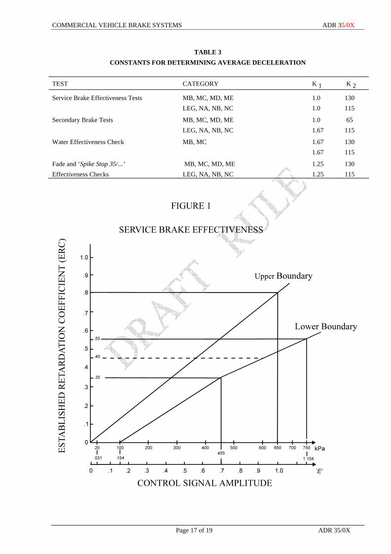
4.1.9 Where the vehicle is equipped to tow a trailer which uses air at a positive pressure, the‘Established Retardation Coefficient’ of the ‘Service Brake System’ measured using the general test conditions of part 6 and the particular test conditions of clause 7.18.1 must be between the upper and lower boundaries of Figures 1 and 2 for each value of ‘Control Signal’ used.
4.1.9.1 Where the vehicle is a variant of a previously tested vehicle and the effects of the changes on braking performance are known by a test conducted on a complete vehicle, a component or a sub-assembly of components, the requirements of this clause can be met by ‘Approved’ calculations.
4.1.10 Where the vehicle has a ‘Rated Towing Capacity’ of more than 4.5 tonnes, either: 4.1.10.1 the vehicle must have certification which provides for the operation of trailer brakes using air at a
positive pressure as described in clause 4.1.9 or 4.1.10.2 the ‘Manufacturer’ must supply to the ‘Administrator’ sufficient data to allow the vehicle’s ‘Service
Brake System’ to be modeled under laden braking conditions. Provision of the data derived from the tests performed as described by clause 7.18.2 will be considered as sufficient to meet the requirements of this clause.
4.1.10.3 Where the vehicle is a variant of a previously tested vehicle and the effects of the changes on braking performance are known by a test conducted on a complete vehicle, a component or a sub-assembly of components, the requirements of this clause can be met by ‘Approved’ calculations.
4.1.11 Where the ‘Service Brake System’ incorporates a single ‘Brake Power Unit 35/...’ an ‘Audible Indicator’ must be provided which must operate at all times when the service brake failure ‘Visible Indicator’ operates as specified in clause 4.2.
4.1.12 Each air reservoir in a compressed air ‘Brake System’ must be fitted with a manual condensate drain valve at the lowest point. An automatic condensate valve may be fitted provided it also drains the lowest point. The manual drain valve may be incorporated in the automatic valve.
COMMERCIAL VEHICLE BRAKE SYSTEMS ADR 35/0X
Page 3 of 19 ADR 35/0X
4.2 Visible Indicator’ 4.2.1 The ‘Visible Indicator’ must operate whenever any of the conditions listed in clauses 4.2.2 to 4.2.4 as
applicable occur while the ignition or electrical control switch is in the “engine on” position or while the engine is running.
4.2.2 For a ‘Service Brake System’ incorporating a hydraulic brake circuit and no ‘Brake Power Unit 35/...’ in that hydraulic circuit, condition A or optionally condition B must be met;
Condition A A.1 When a pressure failure occurs in any part of the ‘Service Brake System’, except for pressure failure
caused by either: A.1.1 a structural failure of a housing that is common to two or more sub-systems; or A.1.2 failure of a component of a ‘Brake Power Assist Unit’. A.2 In the event of such failure, the indicator operation requirement is deemed to be satisfied if the
indicator operates before or upon application of: A.2.1 a differential line pressure of not more than 1.55 MPa between the active and failed brake systems
measured either at a master cylinder outlet, or at a slave cylinder outlet if the master cylinder controls a slave cylinder at a booster unit;
A.2.2 a ‘Pedal Effort 35/...’ of 225 N in the case of unassisted ‘Service Brake Systems’; or A.2.3 a ‘Pedal Effort 35/...’ of 115 N in the case of ’ Service Brake Systems’ with a ‘Brake Power Assist
Unit’. Condition B B.1 When a drop in the level of brake fluid occurs in the reservoir(s), either to less than the
‘Manufacturer’s’ designated minimum level or to less than 25 percent of the reservoir(s) fluid capacity whichever is the greater volume.
B.2 In the case where a master cylinder reservoir also contains fluid for the use of a system other than the brake system, the indicator system and the reservoir must be so designed that the indicator lamp will only be activated when there are variations in the fluid level in that part of the reservoir provided exclusively for the use of the brake system.
4.2.3 For a ‘Service Brake System’ incorporating one or more ‘Brake Power Units 35/...’ in any section of the, ‘Service Brake System’, the ‘Visible Indicator’ must operate when the supply pressure in any one ‘Brake Power Unit 35/...’ drops to or below 65 percent of the ‘Average Operating Pressure’.
4.2.4 For vehicles equipped to tow a trailer using air at positive pressure, when the pressure in the ‘Supply Line 35/...’ drops to or below 450 kPa, the ‘Visible Indicator’ must operate as required by clause 4.2.1.
4.2.4.1 The ‘Visible Indicator’ may also operate when the ‘Supply Line 35/...’ energy level is reduced at a rate of not less than 0.15E/sec provided that in all cases the ‘Visible Indicator’ must operate as required by clause 4.2.1. when the pressure in the ‘Supply Line 35/...’ drops to or below 450 kPa.
4.2.4.2 the ‘Visible Indicator’ must not operate when a trailer is not connected and no other defect is present. The absence of a trailer may be determined by the pressure in the ‘Supply Line 35/...’ dropping to or below 35 kPa.
4.2.5 Where the requirements of clause 4.2 necessitates the provision of more than one system failure sensor, the sensors may be interconnected to actuate only one ‘Visible Indicator’.
4.2.6 As a check of function, the ‘Visible Indicator’ must be so designed that it operates when: 4.2.6.1 the ignition or electrical control switch is turned from the ‘engine off” position to the ‘engine on’
position, and the engine is not operating, and (unless a failure exists in the brake system) it must not operate when the engine is running; or
4.2.6.2 the ignition or electrical control switch is in the ‘engine start’ position, and (unless a failure exists in the brake system) it must not operate after the return of the ignition or electrical control switch to the ‘engine on’ position; or

COMMERCIAL VEHICLE BRAKE SYSTEMS ADR 35/0X
ADR 35/0X Page 4 of 19
4.2.6.3 the ignition or electrical control switch is in a position between the ‘engine on’ position and the ‘engine start’ position, which is designated by the ‘Manufacturer’ as a check position, and (unless a failure exists in the brake system) it must not operate after the return of the ignition or electrical control switch to the “engine on” position; or
4.2.6.4 the engine start circuit is energised and (unless a failure exists in the brake system) it must not operate when the “engine start” circuit is not energised; or
4.2.6.5 the ignition or electrical control switch is in the “engine on” position and the ‘Parking Brake System 35/..’ is engaged for vehicles where the ‘Service Brake System’ failure ‘Visible Indicator’ and the Parking Brake indicator lamp are combined.
4.2.7 For vehicles equipped with an automatic transmission, the operation as a check of indicator function is not required when the transmission control lever is in a “forward” or “reverse” drive position.
4.2.8 The ‘Visible Indicator’ system must be so designed that once having become operative to signal a brake failure it must operate whenever the ignition or electrical control switch is in the “engine on” position and the fault remains uncorrected.
4.2.9 The ‘Visible Indicator’ may take the form of an indicator lamp or of a mechanical signaling device. 4.2.10 Where an indicator lamp is used the lamp must be labeled with at least the word “BRAKE” or, the
symbol for “BRAKE FAILURE” specified in International Standard ISO 2575-2000 - “Road Vehicles - Symbols for controls indicators and tell-tales” placed either directly on the lens or adjacent to it in such a way that the label is illuminated by the same light source as the lens.
4.2.10.1 The letters of the label must be not less than 3 mm high and must be of a contrasting colour to their background when illuminated.
4.2.10.2 If the label is directly on the lens the colour of either label or lens must be red and if the label is not on the lens the colour of the lens must be red.
4.2.10.3 An illuminated lamp may be either steady-burning or flashing. 4.2.11 Where a mechanical signalling device is used, it must display at least the word “BRAKE” in letters not
less than 10 mm high when the signal is deployed. Letters and background must be of contrasting colours, one of which is red.
4.2.12 The ‘Service Brake System’ failure ‘Visible Indicator’ and its specified label or display must be totally located forward of a transverse vertical plane through the point representing the intersection of the steering wheel axis of rotation and the plane of the steering wheel, and totally within the space bounded by:
4.2.12.1 the right-hand internal side wall; 4.2.12.2 a vertical plane along the longitudinal centre line of the vehicle; 4.2.12.3 a horizontal plane through a point on the lower edge of the instrument panel; and 4.2.12.4 a horizontal plane 150 mm above the highest point on the windscreen glass. 4.3 ‘Parking Brake System 35/..’ 4.3.1 The vehicle must be equipped with a ‘Parking Brake System 35/..’ such that in the applied position
retention is effected by mechanical means, and the braking effect is achieved by either: 4.3.1.1 the frictional force developed between two friction surfaces; or 4.3.1.2 the frictional force developed between two friction surfaces, together with a ‘Parking Mechanism
35/...’. 4.3.2 The parking brake ‘Control’ must be separate from the service brake ‘Control’ and incorporate a
device to retain it in the “brake on” position, and it must be designed to minimise the possibility of inadvertent release of the brake. This requirement will be deemed to be satisfied if at least 2 separate and distinct movements are necessary to disengage the parking brake.
4.3.3 The ‘Parking Brake System 35/..’ must incorporate devices which compensate for any increased movement of its components arising from wear. Such devices must themselves contain provision for securing them throughout their working range in any position to which they may be adjusted to or to which they may themselves automatically adjust.

COMMERCIAL VEHICLE BRAKE SYSTEMS ADR 35/0X
Page 5 of 19 ADR 35/0X
4.3.4 The ‘Control’ by which the ‘Parking Brake System 35/..’ is actuated must be located so that it is readily accessible to the driver in the normal driving position.
4.3.5 On every motor vehicle equipped to tow a trailer which uses air at positive pressure the operation of the ‘Parking Brake System 35/..’ must cause the pressure in the ‘Supply Line 35/...’ to drop below 35 kPa.
4.3.6 Once the ‘Supply Line 35/...’ pressure has dropped below 35 kPa in accordance with clause 4.3.5 the ‘Supply Line 35/...’ must be restored to normal when the ‘Parking Brake System 35/..’ is released.
4.3.7 An additional ‘Control’ may be fitted to provide for the independent release of the trailer parking brakes. Once the ‘Supply Line 35/...’ pressure has dropped below 35 kPa in accordance with clause 4.3.5 this control must restore the ‘Supply Line 35/...’ to the normal condition provided that:
4.3.7.1 two independent actions are required: 4.3.7.2 the engine is running; and 4.3.7.3 the ‘Control’ must automatically reset to provide for operation of the ‘Parking Brake System 35/..’ as
described in clause 4.3.5 no later than upon the next application of the ‘Control’ for the ‘Parking Brake System 35/...’.
4.4 Parking Brake Indicator Lamp 4.4.1 If the vehicle is not fitted with a ‘Spring Brake System’ or a ‘Parking Brake System 35/..’ utilizing
‘Lock Actuators’ , it must be provided with a lamp which indicates that the parking brake is engaged. 4.4.2 The lamp may be common with or distinct and separate from any ‘Service Brake System’ failure
‘Visible Indicator’ lamp. 4.4.3 In the case of a common lamp, the lamp must be labeled with the word “BRAKE”; or the symbol for
“BRAKE FAILURE” - specified as Number 4.31 in the ISO document referred to in clause 4.2.10. 4.4.4 In the case of a distinct and separate lamp the lamp must be labeled with at least the words “PARK
BRAKE” or “PARKING BRAKE”; or the symbol for “PARKING BRAKE” specified as Number 4.32 in the ISO document referred to in clause 4.2.10 placed either directly on the lens or adjacent to it in such a way that the label is illuminated by the same light source as the lens.
4.4.5 The letters of the label must be not less than 3 mm high and must be of contrasting colour to their background when illuminated. If the label is directly on the lens the colour of either label or lens must be red and if the label is not on the lens the colour of the lens must be red.
4.4.6 The parking brake indicator lamp and its specified label must be located within the space boundaries specified in clause 4.2.12.
4.5 Secondary Brake Systems 4.5.1 The vehicle must be equipped with a ‘Secondary Brake System’. 4.5.2 Hydraulic ‘Service Brake System’ must be ‘Split Service Brake System’. 4.5.3 If the vehicle is equipped with one or more ‘Brake Power Units 35/...’ the ‘Secondary Brake System’
must be capable of application through the medium of a ‘Control’. 4.5.4 The ‘Control’ of the ‘Secondary Brake System’ must be capable of releasing and applying the
secondary brake after its first application. The ‘Control’ must be so placed that it can be operated by the driver in the normal driving position.
4.5.5 A ‘Secondary Brake System’ may utilise elements of the ‘Service Brake System’. 4.5.6 Where the ‘Secondary Brake System’ is a ‘Spring Brake System’: 4.5.6.1 in a single circuit ‘Service Brake System’, the energy supply system for maintaining the secondary
brake in its released position must include a ‘Stored Energy’ device that does not service any other device or equipment;
4.5.6.2 in the event of failure of the energy supply to any one circuit of a ‘Service Brake System’ employing two or more independent circuits, the energy requirements for retaining the secondary brakes in the released position must be supplied from the ‘Stored Energy’ device(s) of the other circuits or optionally from an independent ‘Stored Energy’ device; and

COMMERCIAL VEHICLE BRAKE SYSTEMS ADR 35/0X
ADR 35/0X Page 6 of 19
4.5.6.3 with the ‘Stored Energy’ device charged to its ‘Average Operating Pressure’ it must have sufficient capacity to permit the ‘Secondary Brake System’ to be applied and released not fewer than:
4.5.6.3.1 Two (2) times when the brakes are adjusted so that the distance traveled by the device which directly actuates the brake shoe or pad is a maximum, or
4.5.6.3.2 Three (3) times when the brakes are adjusted to the ‘Manufacturer’ specifications. 4.5.7 In a vehicle equipped with a ‘Brake Power Assist Unit’ normally supplied with high pressure fluid by
an engine driven pump, a back-up system must be regarded as a ‘Secondary Brake System’ if the back up source of power assistance is immediately energized by a pump driven independently of the vehicle engine.
4.5.8 Every motor vehicle equipped to tow a trailer must be so equipped that its brake system remains operative and has the performance of the Laden Secondary Brake Test (item 7 of Table 1) in the event of the trailer becoming disconnected. This protection must be automatic.
4.5.8.1 Protection systems may vent the trailer ‘Supply Line 35/...’ but this must not commence; 4.5.8.1.1 until the energy level in the ‘Supply Line 35/...’ falls below 0.54 ‘E’ (350 kpa) or, 4.5.8.1.2 if the ‘Supply Line 35/...’ energy level is reducing at a rate of not less than 0.15E/sec (100 kpa/sec),
until the energy level in the ‘Supply Line 35/...’ falls below 0.65 ‘E’(420 kpa). 4.5.9 Every motor vehicle which provides its ‘Secondary Braking System’ by means of a ‘Split Service
Brake System’ and which is equipped to tow a trailer which uses air at positive pressure, must be so equipped that the operation of the ‘Secondary Brake System’ causes a control signal proportional to the degree of braking to be present in the ‘Control Line 35/...’.
4.5.10 An additional ‘Control’ may be fitted to provide for the independent application of a trailer ‘Parking Brake System 38/00’. Operation of the ‘Control’ must cause the pressure in the ‘Supply Line 35/...’ to drop below 35 kPa and remain below 35 kPa independently of the motor vehicle’s ‘Service Brake System’.
4.5.10.1 The ‘Control’ which actuates this function must be located so that it is readily accessible to the driver in the normal driving position and, marked with the words ‘TRAILER EMERGENCY BRAKES’ and a description of how to operate the control, e.g. ‘TRAILER EMERGENCY BRAKES – PULL’. The ‘Control’ must also be marked with the words ‘NOT FOR PARKING’. The letters must be not less than 5 mm high. Letters and background must be contrasting colours, one of which is red.
4.6 Special Provisions for All Vehicles with ‘Hydraulic Brake Systems’ 4.6.1 In cases where the ‘Service Brake System’ incorporates a master cylinder, each service brake sub-
system serviced by the master cylinder must have either: 4.6.1.1 a reservoir which contains fluid exclusively for the use of that service brake sub-system; or 4.6.1.2 a reservoir which contains fluid for the use of 2 or more service brake sub-systems, in which case that
part of the reservoir capacity provided exclusively for the use of each service brake sub-system must be not less than the volume displaced by the master cylinder piston servicing the sub-system, during a full stroke of the piston.
4.6.2 The capacity of each reservoir must be not less than the fluid displacement resulting when all the wheel cylinders or calliper pistons serviced by the reservoir move from a new-lining, fully-retracted position, as adjusted according to the ‘Manufacturer’s’ recommendations to a fully-worn, fully-applied position. For the purpose of this clause, “fully-worn, fully-applied” means that the lining is worn to whichever of the following conditions allows the greatest shoe or pad movement:
4.6.2.1 the limit recommended by the ‘Manufacturer’; 4.6.2.2 level with rivet or bolt heads on riveted or bolted linings; 4.6.2.3 within 3 mm of the pad mounting surface on bonded pads; or
COMMERCIAL VEHICLE BRAKE SYSTEMS ADR 35/0X
Page 7 of 19 ADR 35/0X
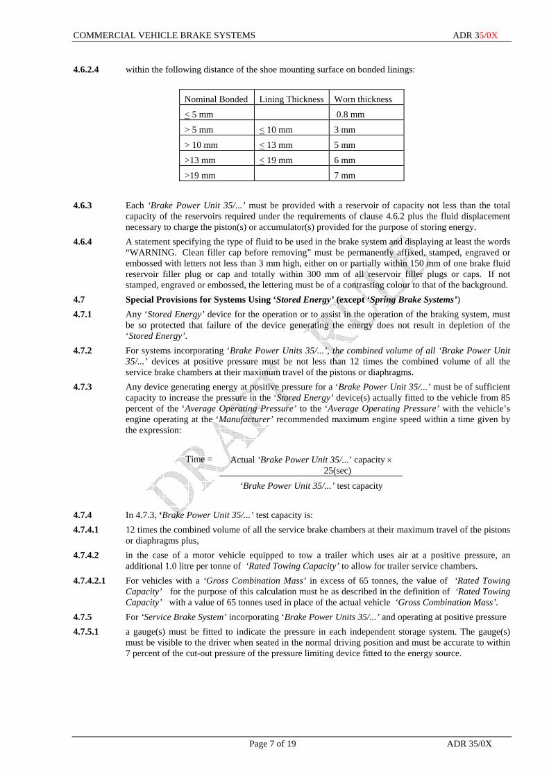
4.6.2.4 within the following distance of the shoe mounting surface on bonded linings:
Nominal Bonded Lining Thickness Worn thickness
< 5 mm 0.8 mm
> 5 mm < 10 mm 3 mm
> 10 mm < 13 mm 5 mm
>13 mm < 19 mm 6 mm
>19 mm 7 mm
4.6.3 Each ‘Brake Power Unit 35/...’ must be provided with a reservoir of capacity not less than the total
capacity of the reservoirs required under the requirements of clause 4.6.2 plus the fluid displacement necessary to charge the piston(s) or accumulator(s) provided for the purpose of storing energy.
4.6.4 A statement specifying the type of fluid to be used in the brake system and displaying at least the words “WARNING. Clean filler cap before removing” must be permanently affixed, stamped, engraved or embossed with letters not less than 3 mm high, either on or partially within 150 mm of one brake fluid reservoir filler plug or cap and totally within 300 mm of all reservoir filler plugs or caps. If not stamped, engraved or embossed, the lettering must be of a contrasting colour to that of the background.
4.7 Special Provisions for Systems Using ‘Stored Energy’ (except ‘Spring Brake Systems’) 4.7.1 Any ‘Stored Energy’ device for the operation or to assist in the operation of the braking system, must
be so protected that failure of the device generating the energy does not result in depletion of the ‘Stored Energy’.
4.7.2 For systems incorporating ‘Brake Power Units 35/...’, the combined volume of all ‘Brake Power Unit 35/...’ devices at positive pressure must be not less than 12 times the combined volume of all the service brake chambers at their maximum travel of the pistons or diaphragms.
4.7.3 Any device generating energy at positive pressure for a ‘Brake Power Unit 35/...’ must be of sufficient capacity to increase the pressure in the ‘Stored Energy’ device(s) actually fitted to the vehicle from 85 percent of the ‘Average Operating Pressure’ to the ‘Average Operating Pressure’ with the vehicle’s engine operating at the ‘Manufacturer’ recommended maximum engine speed within a time given by the expression:
Time = Actual ‘Brake Power Unit 35/...’ capacity ×
25(sec)
‘Brake Power Unit 35/...’ test capacity 4.7.4 In 4.7.3, ‘Brake Power Unit 35/...’ test capacity is: 4.7.4.1 12 times the combined volume of all the service brake chambers at their maximum travel of the pistons
or diaphragms plus, 4.7.4.2 in the case of a motor vehicle equipped to tow a trailer which uses air at a positive pressure, an
additional 1.0 litre per tonne of ‘Rated Towing Capacity’ to allow for trailer service chambers. 4.7.4.2.1 For vehicles with a ‘Gross Combination Mass’ in excess of 65 tonnes, the value of ‘Rated Towing
Capacity’ for the purpose of this calculation must be as described in the definition of ‘Rated Towing Capacity’ with a value of 65 tonnes used in place of the actual vehicle ‘Gross Combination Mass’.
4.7.5 For ‘Service Brake System’ incorporating ‘Brake Power Units 35/...’ and operating at positive pressure 4.7.5.1 a gauge(s) must be fitted to indicate the pressure in each independent storage system. The gauge(s)
must be visible to the driver when seated in the normal driving position and must be accurate to within 7 percent of the cut-out pressure of the pressure limiting device fitted to the energy source.

COMMERCIAL VEHICLE BRAKE SYSTEMS ADR 35/0X
ADR 35/0X Page 8 of 19
4.7.5.2 a pressure test connection complying with clause 4 of ISO Standard 3583-1984 Road vehicles – Pressure test connection for compressed – air pneumatic braking equipment must be fitted at either the inlet to, or in the body of, the brake chamber with the slowest reaction time in each ‘Axle Group’ (in respect of brake timing as specified in clause 7.17).
4.7.5.3 a pressure test connection complying with clause 4 of ISO Standard 3583-1984 Road vehicles – Pressure test connection for compressed – air pneumatic braking equipment must be fitted in the body of the ‘Stored Energy’ device used for the ‘Service Brake System’ which is charged last.
4.7.6 For ‘Service Brake Systems’ incorporating ‘Brake Power Assist Units’ and where the Secondary Brake is not applied by the service brake ‘Control’ , the combined volume of all ‘Stored Energy’ devices must be such that with no replenishment of ‘Stored Energy’ the performance prescribed for the Laden Secondary Brake Test in clause 7.7 must be achieved:
4.7.6.1 where the energy source is a pump, on the eighth actuation of the service brake ‘Control’, after 7 actuations with vehicle stationary, either to full stroke or to the application of a ‘Pedal Effort 35/...’ not less than 685 N whichever occurs first; or
4.7.6.2 where the energy source is the engine of the vehicle, on the fourth actuation of the service brake ‘Control’, after 3 actuations with vehicle stationary, either to full stroke or to the application of a ‘Pedal Effort 35/...’ not less than 685 N, which ever occurs first.
4.7.7 An energy generating device producing energy at negative pressure must be capable of achieving the volume-pressure relationship required to satisfy the conditions specified in clause 4.7.6 in a time not exceeding 3 minutes with:
4.7.7.1 the engine operating at not greater than 65 percent of speed corresponding to either maximum power output or governed speed where the energy generating device is a vacuum pump; or
4.7.7.2 the engine operating at idle speed with the gear selector in “neutral” position where the engine itself is the energy generating device.
4.7.8 Where the device generating the energy for any number of ‘Brake Power Unit 35/...’ supplies energy to other devices, the design shall be such that all the ‘Brake Power Unit 35/...’ are preferentially charged to an energy level of not less than 0.69 ‘E’ (450 kpa).
4.7.9 In the case of ‘Service Brake Systems’ incorporating ‘Brake Power Unit 35/...’ the design must be such that all ‘Brake Power Unit 35/...’ must preferentially service the brake system if the energy level falls below 0.69 ‘E’ (450 kpa).
5 PERFORMANCE REQUIREMENTS
5.1 The vehicle must be capable of meeting the range of performance tests set out in the Table 1, subject to the general test conditions of part 6 and the particular test conditions of part 7.
5.2 The sequence of testing may be in the order set out in the Table. Where the sequence of testing is not in the order set out in the Table, the tests must be grouped as follows:-
Items 1 & 2; Items 3 - 5 inclusive; Items 6 - 10 inclusive Items 11-12 and (optionally) item 13 (if not conducted with items 6-10);
6 GENERAL TEST CONDITIONS
6.1 The ambient temperature at the test site must be within the range of 0°C to 40°C. 6.2 The following adjustments must be checked before commencing tests, and set to vehicle
‘Manufacturer’s’ recommendations: 6.2.1 injection or ignition timing; 6.2.2 engine idle speed; 6.2.3 engine governed speed if adjustable governor is fitted; and 6.2.4 all brake adjustments.
COMMERCIAL VEHICLE BRAKE SYSTEMS ADR 35/0X
Page 9 of 19 ADR 35/0X
6.3 The tyres fitted to the vehicle must be of the size and type specified by the vehicle ‘Manufacturer’ as original equipment for the vehicle, and must be inflated to pressures not less than those recommended by the vehicle ‘Manufacturer’.
6.4 The ‘Friction Elements’ of the vehicle brakes must be of the make and grade specified by the vehicle ‘Manufacturer’.
6.5 Decelerations must be conducted on sections of a test track or roadway that meets the following requirements:
6.5.1 in the case of the Service Brake Fade Test, the surface must be substantially level and any effective upward average gradient between the start and end of each deceleration test section must not exceed one percent.
The requirements of this clause are deemed to be met if it is demonstrated that over the total number of brake applications of the Service Brake Fade Test sequence of clause 7.9, the total effective contribution to vehicle retardation of the deceleration test section’s gradients is not greater than the vehicle retardation which would result from an average upward gradient of not more than one percent;
6.5.2 in the case of other deceleration tests, the upward gradient, if any, must not exceed one percent. 6.6 Except when conducting burnishing procedures, decelerations must be conducted in a direction such
that the component of wind velocity opposite to the direction of travel of the vehicle does not exceed 15 km/h.
6.7 Where a test requires that the gear selector be in “drive” the transmission selector control must be in the control position recommended by the ‘Manufacturer’ as appropriate to the speed of the vehicle at the commencement of the deceleration mode.
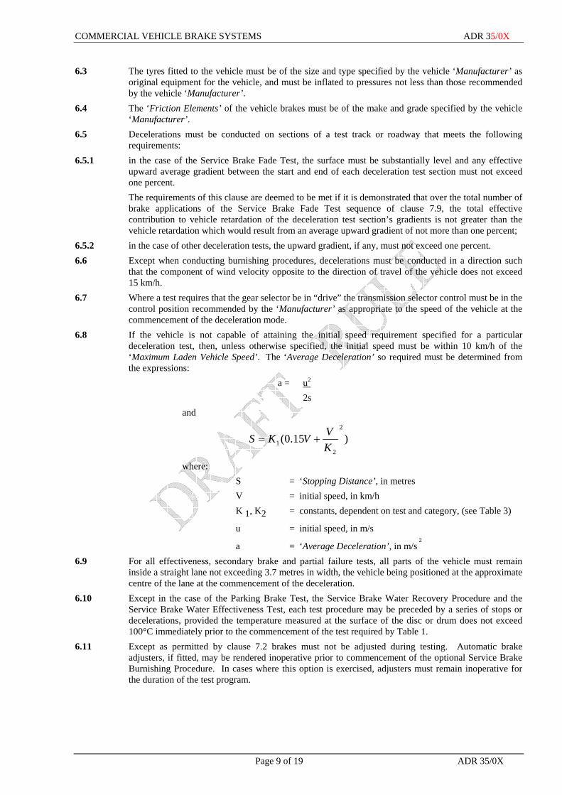
6.8 If the vehicle is not capable of attaining the initial speed requirement specified for a particular deceleration test, then, unless otherwise specified, the initial speed must be within 10 km/h of the ‘Maximum Laden Vehicle Speed’. The ‘Average Deceleration’ so required must be determined from the expressions:
a = u2 2s
and
)15.0(2
21 K
VVKS +=
where: S = ‘Stopping Distance’, in metres V = initial speed, in km/h K 1, K2 = constants, dependent on test and category, (see Table 3)
u = initial speed, in m/s
a = ‘Average Deceleration’, in m/s 2
6.9 For all effectiveness, secondary brake and partial failure tests, all parts of the vehicle must remain inside a straight lane not exceeding 3.7 metres in width, the vehicle being positioned at the approximate centre of the lane at the commencement of the deceleration.
6.10 Except in the case of the Parking Brake Test, the Service Brake Water Recovery Procedure and the Service Brake Water Effectiveness Test, each test procedure may be preceded by a series of stops or decelerations, provided the temperature measured at the surface of the disc or drum does not exceed 100°C immediately prior to the commencement of the test required by Table 1.
6.11 Except as permitted by clause 7.2 brakes must not be adjusted during testing. Automatic brake adjusters, if fitted, may be rendered inoperative prior to commencement of the optional Service Brake Burnishing Procedure. In cases where this option is exercised, adjusters must remain inoperative for the duration of the test program.
COMMERCIAL VEHICLE BRAKE SYSTEMS ADR 35/0X
ADR 35/0X Page 10 of 19
6.12 Except where clause 6.8 applies any vehicle speed specified must be achieved within a tolerance of + 5, - 1 km/h.
6.13 Where an ‘Antilock System’ is fitted, it must be engaged throughout all tests except the partial failure tests where a failure in the ‘Antilock System’ is simulated.
6.13.1 Additional tests may be optionally conducted with the ‘Antilock System’ disengaged to demonstrate that the vehicle meets the performance requirements of all tests specified in part 7 when a failure in the ‘Antilock System’ is simulated.
6.14 Where a ‘Retractable Axle’ is fitted, a vehicle has a number of ‘Configurations’. It must be demonstrated that in each ‘Configuration’, the vehicle complies with the laden condition requirements of this Rule for that ‘Configuration’. The laden condition for a ‘Configuration’ with the ‘Axle’ retracted must be considered to be when the ‘Axle Group’ is laden to the ‘Prescribed Transition Mass’ for the ‘Configuration’ being considered. As the vehicle must automatically change its ‘Configuration’ at the ‘Prescribed Transition Mass’ by lowering an ‘Axle’, for the purposes of demonstrating compliance with the requirements of this clause, the automatic system for lowering the ‘Axle’ may be defeated.
6.14.1 The requirements of clause 6.14 do not apply to; 6.14.1.1 the ‘Service Brake System’ compatibility requirements for vehicles capable of drawing a trailer as
described in clause 4.1.9. This requirement need only be demonstrated in the ‘Configuration’ with all ‘Axles’ in the ‘Fully Down’ position and in the maximum laden condition as specified in clause 7.18; or
6.14.1.2 the Service Brake Actuation Time Test as described in clause 7.17. 6.14.2 It must be demonstrated that in each ‘Configuration’, including with the ‘Retractable Axle’ manually
lowered if the manual ‘Control’ for lowering of ‘Retractable Axle’ is fitted, the vehicle complies with the requirements of this rule in the lightly laden condition.
7 PARTICULAR TEST CONDITIONS
7.1 Pre-test Instrumentation Check 7.1.1 The number of decelerations for the purpose of instrumentation checks must not exceed 20. 7.1.2 Such decelerations must be conducted from a speed of not more than 40 km/h and any instantaneous
deceleration must not exceed 3 m/s 2. 7.2 Service Brake Burnishing Procedure 7.2.1 Burnishing, if conducted, consists of any desired number of decelerations to the ‘Manufacturer’s’
recommendation. 7.2.2 On completion of the burnishing procedure, if conducted, the brake system may be adjusted in
accordance with the ‘Manufacturer’s’ recommendation. 7.3 Service Brake Lightly Laden Effectiveness Test A series of tests must be conducted in the manner described in Table 1 (Item 3). The vehicle will be
deemed to satisfy the requirements of this test, if all the parameters specified are met on at least one test within a number of tests that must not exceed 6.
7.4 Lightly Laden Secondary Brake Test 7.4.1 Where the secondary brake is not applied by the service brake ‘Control’, the vehicle must be
decelerated using only the ‘Secondary Brake System’ and deemed to satisfy the requirements of this test, if all the parameters specified in Table 1 (Item 4) are met in at least one test within a number of tests that must not exceed 6.
7.4.2 Where the secondary brake is applied by the service brake ‘Control’, the vehicle must be deemed to satisfy the requirements of this test if all the parameters specified in Table 1 (Item 4) are met in at least one test within a number of tests that must not exceed 6 for each single failure of a fluid system, including where appropriate:
7.4.2.1 each sub-system of a ‘Split Service Brake System’; and 7.4.2.2 failure of energy assistance in a ‘Brake Power Assist Unit’
COMMERCIAL VEHICLE BRAKE SYSTEMS ADR 35/0X
Page 11 of 19 ADR 35/0X
7.5 Lightly Laden Partial Failure Test . 7.5.1 The requirements of this clause only applies to a vehicle fitted with a brake system where the
secondary brake is applied by the service brake ‘Control’. The vehicle will be deemed to satisfy the requirements of this test if all the parameters specified in Table 1 (Item 5) are met in at least one deceleration mode within a number of deceleration modes which must not exceed 6 for each single type of partial failure, including:
7.5.1.1 inoperative ‘Antilock System’; and 7.5.1.2 inoperative ‘Variable Proportioning Brake System’. 7.5.2 One single failure must be induced prior to each set of deceleration modes and the vehicle must be
restored at the completion of each set. 7.6 Service Brake Laden Effectiveness Test A series of tests must be conducted in the manner described in Table 1 (Item 6). The vehicle will be
deemed to satisfy the requirements of this test, if all the parameters specified are met on at least one test within a number of tests that must not exceed 6.
7.7 Laden Secondary Brake Test The test procedure and determination of compliance must be as specified in clause 7.4, except that the
vehicle must be at ‘Maximum Loaded Test Mass 35/...’ and the test parameters to be achieved are as described in Table 1 (Item 7).
7.8 Laden Partial Failure Test The test procedure and determination of compliance must be as specified in clause 7.5, except that the
vehicle must be at ‘Maximum Loaded Test Mass 35/...’ and the test parameters to be achieved are as described in Table 1 (Item 8).
7.9 Service Brake Fade Test 7.9.1 In the case of vehicles in categories MB, MC, MD and NA, 15 successive deceleration tests must be
conducted at intervals no greater than 55 seconds apart, such that for an initial speed V 1 and a final speed V 2 (km/h)
(V12 - V2
2 ) > 7,500. 7.9.2 In the case of vehicles in categories ME, NB and NC, 20 successive deceleration tests must be
conducted each not more than 70 seconds after the preceding one and with the total of 20 applications completed within 20 minutes, such that for an initial speed V 1 and a final speed V 2 (km/h)
(V12 - V2
2 ) ≥ 2,700. 7.9.3 The initial speed must be maintained for at least 10 seconds prior to each deceleration. 7.9.4 If the vehicle is not capable of attaining the initial speed required by clause 7.9.1. or clause 7.9.2, then
the speed employed in each mode for the initial speed must be not less than 80 percent of the ‘Maximum Laden Vehicle Speed’ and the final speed must not be greater than half the initial speed.
7.9.5 During all deceleration modes the lowest numerical overall drive ratios as specified in clause 6.7 must be continuously engaged. Deceleration modes must be conducted from the initial speed to the final speed.
7.9.6 During acceleration periods the drive train must be employed to regain the initial speed in the shortest possible time.
7.9.7 Notwithstanding the foregoing requirements, changes of vehicle direction essential to testing and negotiation of curved sections of track may be undertaken at constant vehicle speed.
7.9.8 If the vehicle’s performance characteristics are such as to preclude it from maintaining the specified maximum interval between successive brake applications, the time interval may be increased to the minimum time required by the vehicle to achieve the specified initial speed and to maintain it for 10 seconds before each successive deceleration mode.
7.9.9 Vehicles must attain a sustained deceleration of not less than 3 m/s 2 during the first deceleration mode. Subsequent deceleration must be conducted employing a ‘Control’ force not less than that established during the first deceleration mode without regard to the actual deceleration achieved.
COMMERCIAL VEHICLE BRAKE SYSTEMS ADR 35/0X
ADR 35/0X Page 12 of 19
7.9.10 The Service Brake Fade Test must be followed immediately by the Service Brake Fade Effectiveness Check.
7.10 Service Brake Fade Effectiveness Check The vehicle must be accelerated over a distance not exceeding 1.6 km from the final speed attained at
the conclusion of the deceleration mode of the Service Brake Fade Test to the initial speed specified in Table 1 (Item 10) and the test carried out in accordance with that Item. The vehicle must be deemed to satisfy the requirements of this test if the deceleration achieved is not less than that specified in Table 1 (Item 10).
7.11 Parking Brake Test 7.11.1 This test must be conducted on a gradient of at least 18 percent, where the vertical rise is expressed as a
percentage of the horizontal distance traveled to achieve this rise. The vehicle must be positioned on the gradient such that its longitudinal axis is parallel to the direction of the gradient. The ‘Parking Mechanism 35/...’ (if fitted) must be disengaged. The service brake must be applied, transmission disengaged, and parking brake must be applied by a single application of the force specified, except that a series of applications to achieve the specified force may be made in the case of a parking brake design that does not allow the application of the specified force in a single application. The service brake must be released, for a period of not less than 5 minutes. The vehicle must then be parked in the reverse position on the gradient for not less than 5 minutes with the vehicle in condition described above.
7.11.2 The vehicle is deemed to pass this test if: 7.11.2.1 for each of the 5 minute periods it remains stationary on the gradient; and 7.11.2.2 the force required to actuate the parking brake does not exceed 685 N in the case of a foot-operated
parking brake, and does not exceed 590 N applied at the centre of the handgrip, or not closer than 35 mm from the free end of the actuation lever, in the case of a hand-operated parking brake.
7.11.3 If the vehicle does not remain stationary re-application of the service brake to hold the vehicle stationary, with re-application of the specified force to the parking brake ‘Control’ (without release of the ratcheting or other holding mechanism of the parking brake) may be used twice to attain a stationary position.
7.11.4 In cases where the ‘Parking Brake System 35/..’ does not utilise the service brake ‘Friction Elements’, the ‘Friction Elements’ of the system may be burnished to the vehicle ‘Manufacturer’s’ recommendation prior to the test.
7.12 Service Brake Actuating Time Test 7.12.1 For vehicles using air at positive pressure as the operating fluid and incorporating one or more ‘Brake
Power Units 35/..’. 7.12.2 The test is conducted while the vehicle is stationary. 7.12.3 Before commencing the test the ‘Stored Energy’ device(s) must be charged to not more than the
‘Average Operating Pressure’ and the brakes must be adjusted according to the ‘Manufacturer’s’ specifications for normal use.
7.12.4 The service brake ‘Control’ must be operated through a full working stroke by an operator seated in the normal driving position.
7.12.5 The pressure at the slowest reacting brake chamber must attain a level not less than 65 percent of the ‘Average Operating Pressure’ within a period not exceeding 600 milliseconds measured from the instant the ‘Control’ leaves the ‘Initial Brake Control Location’.
7.12.6 The brakes must be kept applied until the air pressure in the brake chamber has stabilised. The brakes must then be fully released.
7.12.8 For a vehicle equipped to tow a trailer which uses air at positive pressure as the brake operating fluid; 7.12.8.1 when the service brake ‘Control’ is operated through a full working stroke by an operator seated in the
normal driving position, the pressure measured at the extremity of a pipe 2.5 m long with an internal diameter of 13 mm which must be joined to the ‘Coupling Head’ of the ‘Control Line 35/...’ must reach 420 kPa within 400 milliseconds of the instant the ‘Control’ leaves the ‘Initial Brake Control Location’.

COMMERCIAL VEHICLE BRAKE SYSTEMS ADR 35/0X
Page 13 of 19 ADR 35/0X
During this test a volume of 385 ± 5 cm 3 (which is deemed to be equivalent to the volume of a pipe 2.5 m long with an internal diameter of 13 mm and under a pressure of 6.5 bar) must be connected to the ‘Coupling Head’ of the ‘Supply Line 35/...’; and
7.12.8.2 for a vehicle designed for use as a road train prime mover, having fully applied the service brake ‘Control’ and the pressure measured at the extremity of a pipe 2.5m long with an internal diameter of 13 mm which must be joined to the ‘Coupling Head’ of the ‘Control Line 35/...’ has stabilised, when the service brake ‘Control’ is fully released the pressure measured at the extremity of the 2.5 m long pipe with an internal diameter of 13 mm joined to the ‘Coupling Head’ of the ‘Control Line 35/...’ must fall below 35 kPa within 650 milliseconds of the ‘Control’ being released. During this test a volume of 385 ± 5 cm 3 (which is deemed to be equivalent to the volume of a pipe 2.5 m long with an internal diameter of 13 mm and under a pressure of 6.5 bar) must be connected to the ‘Coupling Head’ of the ‘Supply Line 35/...’.
7.13 Service Brake Compatibility Test 7.13.1 Vehicles equipped to tow a trailer which uses air at positive pressure must be laden to the Group ‘Axle
Load’ limits as specified in Table 2 or the manufacturers ‘GVM’ whichever is the lesser, and braked to a stop from initial speed of 60 km/h. For the first test a ‘Control Signal’ of 0.2 ‘E’ (130 kPa) measured at the ‘Coupling Head’ must be used. Subsequent tests must be conducted increasing the ‘Control Signal’ in increments of not greater than 0.2 ‘E’ (130 kPa) until an ‘Established Retardation Co-efficient’ of not less than 0.45 is reached.
7.13.2 For the purposes of clause 4.1.10.2, where the vehicle has a ‘Rated Towing Capacity’ of more than 4.5 tonnes and the ‘Manufacturer’ elects not to provide certification which provides for the operation of trailer brakes using air at a positive pressure, the response of the ‘Service Brake System’ must be characterised as follows. The vehicle must be laden to the ‘Group Axle Load’ limits as specified in Table 2 or the manufacturers ‘GVM’ whichever is the lesser, and a series of tests conducted braking the vehicle to a stop from initial speed of 60 km/h. The output energy level of the ‘Service Brake System’, ‘Control’ and the ‘ERC’ achieved must be recorded for each test. For the first test an ‘ERC’ in the range 0.05 to 0.1 must be achieved. Subsequent tests must be conducted increasing the ‘ERC’ in not less than 5 evenly spaced steps until an ‘ERC’ of not less than 0.45 is reached.
7.13.3 The ‘Service Brake System’ ‘ERC’ must be determined according to the following as required:
)278.0(00394.0 2
VTSVERC
R−=
ERC VT TR
=−
0 0283.
where: V is the initial speed in km/h S is the ‘Stopping Distance’ in metres T is the ‘Stopping Time’ in seconds T
R is the response time measured from the time the
‘Control’ leaves the ‘Initial Brake Control Location’ until the energy level at the least favoured actuator reaches 65% of ‘Average Operating Pressure’ and is measured in a separate test in accordance with clause 7.17.2 to 7.17.5.
8 ALTERNATIVE STANDARDS 8.1 The technical requirements of ECE R 13/01 to 13/09 “Braking” are deemed to be equivalent to the
technical requirements of this rule. 8.2 Where a vehicle is equipped with an ‘Antilock System’ operating on 24 Volts, the voltage must be
marked on the plug and a warning must be provided in the cabin to advise drivers.
COMMERCIAL VEHICLE BRAKE SYSTEMS ADR 35/0X
ADR 35/0X Page 14 of 19
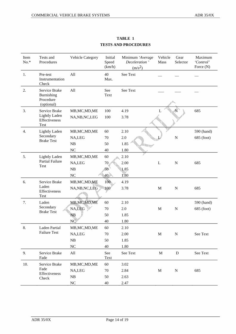
TABLE 1 TESTS AND PROCEDURES
Item No.*
Tests and Procedures
Vehicle Category Initial Speed (km/h)
Minimum ‘Average Deceleration ’
(m/s2)
Vehicle Mass
Gear Selector
Maximum ‘Control’ Force (N)
1. Pre-test Instrumentation Check
All 40 Max.
See Text __ __ __
2. Service Brake Burnishing Procedure (optional)
All See Text
See Text ___ ___ __
3. Service Brake Lightly Laden Effectiveness Test
MB,MC,MD,ME NA,NB,NC,LEG
100 100
4.19 3.78
L N 685
4. Lightly Laden Secondary Brake Test
MB,MC,MD,ME NA,LEG NB NC
60 70 50 40
2.10 2.0 1.85 1.80
L
N
590 (hand) 685 (foot)
5. Lightly Laden Partial Failure Test
MB,MC,MD,ME NA,LEG NB NC
60 70 50 40
2.10 2.00 1.85 1.80
L
N
685
6. Service Brake Laden Effectiveness Test
MB,MC,MD,ME NA,NB,NC,LEG
100 100
4.19 3.78
M
N
685
7. Laden Secondary Brake Test
MB,MC,MD,ME NA,LEG NB NC
60 70 50 40
2.10 2.0 1.85 1.80
M
N
590 (hand) 685 (foot)
8. Laden Partial Failure Test
MB,MC,MD,ME NA,LEG NB NC
60 70 50 40
2.10 2.00 1.85 1.80
M
N
See Text
9. Service Brake Fade
All See Text
See Text M D See Text
10. Service Brake Fade Effectiveness Check
MB,MC,MD,ME NA,LEG NB NC
60 70 50 40
3.02 2.84 2.63 2.47
M
N
685

COMMERCIAL VEHICLE BRAKE SYSTEMS ADR 35/0X
Page 15 of 19 ADR 35/0X
Item No.*
Tests and Procedures
Vehicle Category Initial Speed (km/h)
Minimum ‘Average Deceleration ’
(m/s2)
Vehicle Mass
Gear Selector
Maximum ‘Control’ Force (N)
11. Parking Brake Test
All __ __ M N 590(hand) 685(foot)
12. Service Brake Actuating Time Test
See Text N.A. N.A. N.A. N.A. See Text
13. Service Brake Compatibility Test
See Text 60 See Text Table 2 N 685
* Item No. also corresponds to sub-clause number of clause 7. “M” means ‘Maximum Loaded Test Mass 35/...’ . “L” means ‘Lightly Loaded Test Mass 35/...’ . “D” means transmission control in “drive” position appropriate to test speed. “N” means transmission control in “neutral” position “R” means transmission control in “reverse” position “N.A” means not applicable
COMMERCIAL VEHICLE BRAKE SYSTEMS ADR 35/0X
ADR 35/0X Page 16 of 19
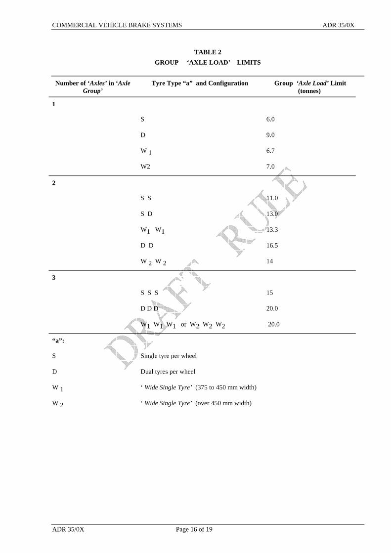
TABLE 2 GROUP ‘AXLE LOAD’ LIMITS
Number of ‘Axles’ in ‘Axle
Group’ Tyre Type “a” and Configuration Group ‘Axle Load’ Limit
(tonnes)
1
S 6.0
D 9.0
W 1 6.7
W2 7.0
2
S S 11.0
S D 13.0
W1 W1 13.3
D D 16.5
W 2 W 2 14
3
S S S 15
D D D 20.0
W1 W1 W1 or W2 W2 W2 20.0
“a”:
S Single tyre per wheel
D Dual tyres per wheel
W 1 ‘ Wide Single Tyre’ (375 to 450 mm width)
W 2 ‘ Wide Single Tyre’ (over 450 mm width)
COMMERCIAL VEHICLE BRAKE SYSTEMS ADR 35/0X
Page 17 of 19 ADR 35/0X
TABLE 3 CONSTANTS FOR DETERMINING AVERAGE DECELERATION
TEST CATEGORY K 1 K 2
Service Brake Effectiveness Tests MB, MC, MD, ME 1.0 130 LEG, NA, NB, NC 1.0 115
Secondary Brake Tests MB, MC, MD, ME 1.0 65 LEG, NA, NB, NC 1.67 115
Water Effectiveness Check MB, MC 1.67 130 1.67 115
Fade and ‘Spike Stop 35/...’ MB, MC, MD, ME 1.25 130 Effectiveness Checks LEG, NA, NB, NC 1.25 115

COMMERCIAL VEHICLE BRAKE SYSTEMS ADR 35/0X
ADR 35/0X Page 18 of 19
FIGURE 2
Service Brake Effectiveness - Unladen ERC
0.
0.
0.
0.
0.
0.
0.
0.
0.
0.
1.
0. 0. 0. 0. 0. 0. 0. 0. 0. 0. 1.
ADR
ECE R13 - Tractor Unladen Upper

COMMERCIAL VEHICLE BRAKE SYSTEMS ADR 35/0X
Page 19 of 19 ADR 35/0X
APPENDIX 1 Special Provisions for vehicles incorporating an ‘Antilock System’.
1.1 At speeds exceeding 15 km/h, the wheels on at least one axle in each axle group must remain unlocked
when a ‘Control’ force of 685 N is suddenly applied on the ‘Control’ or in the case of a ‘Control’ which solely modulates ‘Stored Energy’, full stroke of the ‘Control’ is suddenly applied , when braking from an initial speed of 40 km/h and also from an initial speed of 80 km/h (or greater) on a road surface having approximately uniform surface friction on both sides of the vehicle.
1.1.1 This test is to be performed with the vehicle laden to ‘Lightly Loaded Test Mass 35/...’ and again with the vehicle laden to ‘Maximum Loaded Test Mass 35/...’.
1.1.2 Brief periods of locking of the wheels will, however, be allowed but stability must not be affected. 1.1.3 The general test conditions from part 7 and the particular test conditions from clauses 7.3 and 7.6
including the requirements for deceleration must be used except that the requirements of this clause must be met on each test.
1.1.4 These tests can be combined with those required in clauses 7.3 and 7.6. and can be conducted at any point in the brake test sequence.
1.2 Any break in the supply of electricity to the ‘Antilock System’ and any electrical failure of the ‘Antilock System’ must be signalled to the driver by an optical warning signal appropriately labelled and located in accordance with clause 4.2.12. The lamp may be common with or distinct and separate from any ‘Service Brake System’ failure ‘Visible Indicator’ lamp.
1.2.1 In case of NC category vehicles, the warning signal must be; 1.2.1.1 red or yellow if after the failure of ‘Antilock System’, the vehicle meets the performance requirements
of all tests specified in part 7. 1.2.1.2 red, if after the failure of ‘Antilock System’, the vehicle does not meet the performance requirements of
all tests specified in part 7. 1.2.2 In case of vehicles other than NC category vehicles, the warning light must be red or yellow. 1.2.3 The warning signal must light up when the ‘Antilock System’ is energised and must go off after not less
than 2 seconds or at the latest when the vehicle reaches a speed of 15 km/h and no defect is present. 1.3 Where a vehicle is equipped to tow a trailer with an ‘ATM’ of more than 4.5 tonnes and it is fitted with
an electrical connection for the ‘Antilock System’: 1.3.1 The vehicle must have a permanent electrical supply system for connection to trailers using a special
connector conforming to DIN Standard 72570 configured for 12 volt operation or ISO/DIN7638:1996configured for 12 or 24 volt operation. If configured for 24 volt operation, the voltage must be marked on the plug and a warning label must be provided in the cabin to warn the driver. The power supply must provide DC current having a nominal voltage level of 12 volts or 24 volts.
1.3.2 The connector must be wired to have the following functions: Pin 1 +ve high current trailer solenoid valve supply, 10 amps minimum continuous rated capacity 15
amps maximum capacity Pin 2 +ve low current trailer electronic unit supply, 4 amps minimum rated capacity Pin 3 -ve low current trailer electronic unit supply, 6 amps minimum rated capacity Pin 4 -ve high current trailer solenoid valve supply, 10 amps minimum continuous rated capacity 15
amps maximum capacity Pin 5 trailer ‘Antilock System’ failure, switched to -ve (eg pin 3 or pin 4) upon fault detection, 2 amps
minimum rated capacity. 1.3.3 Either the optical warning lamp specified in clause 1.2.1 of this APPENDIX or an additional yellow
optical warning signal (appropriately labelled) must light up whenever Pin 5 of the connector specified in clause 1.3.2 of this APPENDIX is connected to ground or a -ve connector.