australian broadcasting planning …happy.emu.id.au/lab/info/digtv/files/draft_hand.pdfthe...
TRANSCRIPT

AUSTRALIAN BROADCASTINGPLANNING HANDBOOK
FOR
DIGITAL TERRESTRIAL TELEVISION BROADCASTING
DRAFT12 NOVEMBER 1998


Page 1
CONTENTS
INTRODUCTION......................................................................................................................... 3Existing and Planned Broadcasting Services ................................................................................ 3
Application.................................................................................................................................. 4
PROPAGATION OF RADIO WAVES ....................................................................................... 5Field Strength Prediction Models................................................................................................. 5
RECEPTION ................................................................................................................................ 6Notional Receiving Installation .................................................................................................... 6
Coverage Criteria (Availability) ................................................................................................... 6
Measurement Height / Fixed Antenna Reception.......................................................................... 7
Maximum Field Strength Beyond the Licence Area...................................................................... 7
TRANSMISSION ......................................................................................................................... 8Radiated Signal Characteristics (Emission Standards) .................................................................. 8
Maximum Exposure Levels ......................................................................................................... 8
Modulation.................................................................................................................................. 9
Carriers / Guard Interval.............................................................................................................. 9
Channel Offsets ..........................................................................................................................10
Effective Radiated Power (ERP) ................................................................................................10
Transmit Antenna Radiation Patterns..........................................................................................10
Beam Tilt ...................................................................................................................................10
Null Fill......................................................................................................................................11
Location of Transmit Site ...........................................................................................................11
Polarisation ................................................................................................................................11
INTERFERENCE........................................................................................................................12Interference Criteria ...................................................................................................................12
Tropospheric/Continuous Interference (Fading Range) ...............................................................12
Protection Ratios (PR) ...............................................................................................................13
Intermediate Frequency (IF) .......................................................................................................13
Antenna discrimination ...............................................................................................................14
Interference Summation..............................................................................................................14
Maximum Field Strength to Prevent Receiver Overload..............................................................14
Interference Management ...........................................................................................................15
Electromagnetic Compatibility....................................................................................................15

Page 2
MISCELLANEOUS ....................................................................................................................16Ancillary Devices .......................................................................................................................16
TELEVISION BROADCASTING SERVICE BANDS..............................................................17
NOTIONAL RECEIVER ............................................................................................................19
PROTECTION RATIOS.............................................................................................................21
MODULATION SCHEMES.......................................................................................................26
REFERENCE DOCUMENTATION ..........................................................................................27
WEBSITES ..................................................................................................................................28

Page 3
INTRODUCTION
The Australian Broadcasting Planning Handbook for Digital Terrestrial Television Broadcasting(The DTTB Handbook) provides a convenient single publication which includes the planningparameters, measurement methods and best practice that could be used for the detailed planning oftransmission facilities for digital television.
The planning criteria for VHF/UHF digital television planning in Australia has been largely based onplanning recommendations and reports published by the International Telecommunication Union(ITU). These recommendations and reports were developed and accepted at an international level inconsultation with many member countries. Australia is an active member of the ITU.
The Australian Broadcasting Authority (ABA) also acknowledges the unique role of StandardsAustralia, in particular Standards Australia having ultimate responsibility for publishing the technicalparameters to be used for transmission and reception of digital terrestrial television in Australia, as anAustralian Standard.
The parameters detailed in the DTTB Handbook were developed in close consultation with theDigital Television Channel Planning Consultative Group, and will be revised to reflect currentplanning practices and international developments, taking account of the technical characteristics ofreceivers available in the market.
EXISTING AND PLANNED BROADCASTING SERVICES
To carry out the necessary channel selection and analysis process, certain information will be neededabout the preferred channel groupings for an area and established and proposed broadcastingservices.
Information about licensed broadcasting services is available in the Radio and TelevisionBroadcasting Stations Book 1998, published by the ABA. This publication is also be available onthe ABA’s internet website on http://www.aba.gov.au. Alternatively, information aboutbroadcasting stations will be available in a download format also from the ABA’s internet website.The data is regularly extracted from the ABA’s database, and is ideal for those wishing to obtain up-to-date information on licensed broadcasting services.
Frequency tables for the analog television bands, showing analog channels allotted to particular areasin Australia, were published in the ABA’s Frequency Allotment Plan August 1994. That publicationdoes not contain information about subsequently planned services.
The ABA is examining ways in which information regarding planned analog and eventually digitaltelevision services can be made readily available.
Digital television channels will not normally be assigned in advance of detailed planning andacceptance of the Digital Conversion Schemes and Implementation Plans. However, the ABA mayassign some interim channels in advance for the purpose of testing, where planning policyconsiderations allow. It is acknowledged that test transmissions will be required by somebroadcasters to provide useful planning information for the process.
For the purpose of analog television and radio planning refer to the ABA’s Technical PlanningGuidelines (TPGs) and the Interim Australian Broadcasting Planning Handbook (The AnalogHandbook).

Page 4
APPLICATION
For the purpose of developing the Digital Channel Plan (DCP), channel selection will only considerthose 7 MHz channels occupying the Band III, Band IV and Band V television transmission bandsspecified below.
TV Transmission Band Frequency Range(MHz)
Channels
III 174 - 230 VHF Channels 6 to 12
IV 526 - 582 UHF Channels 28 to 35
V 582 - 820 UHF Channels 36 to 69
Refer to Appendix 1 for more detailed information on the Australian television broadcasting servicesbands in particular channel numbers, frequency limits and other uses.

Page 5
PROPAGATION OF RADIO WAVES
FIELD STRENGTH PREDICTION MODELS
All propagation calculations are subject to some degree of uncertainty, because of the simplificationsthat are made and the limited accuracy of topographic and other data. As a basis for determining theDigital Channel Plan, Recommendation ITU-R P.370-7 may be used to predict the field strengthvalues for coverage and interference calculations.
The Interim Australian Broadcasting Planning Handbook (The Analog Handbook) also detailspropagation mechanisms and models that may be suitable for VHF/UHF digital broadcastingpredictions.
Other more refined field strength prediction methods and models, in particular the ABA’s modifiedBBC prediction software, the Canadian CRC-COV prediction software package, and the MapinfoDecibel Planner, are currently being assessed by various broadcasting bodies for suitability inAustralian conditions. The BBC prediction model, CRC-COV package and Decibel Planner may bemore appropriate for detailed interference and coverage planning.
In addition to the prediction models, the existing analog channel arrangements and structures give anempirical understanding of actual propagation from existing sites.

Page 6
RECEPTION
NOTIONAL RECEIVING INSTALLATION
The Handbook is based on the assumption that the receiver population, the viewers’ receivinginstallations, will have certain characteristics. The characteristics of the receiver are describedthroughout the handbook as the ‘notional receiving installation’, specified in Appendix 2.
The field strengths of the various wanted and unwanted signals are considered to produce voltages atthe receiver terminals which depend on the polarisation and directivity discrimination of the receivingantenna system. Polarisation and directivity discrimination of a typical antenna system are discussedin later sections.
COVERAGE CRITERIA (AVAILABILITY)
The coverage area of a transmitter is the area in which a specified standard of reception can beobtained with a notional receiving installation at a percentage of locations. The field strengths whichare considered to provide adequate digital reception in the absence of interference from othersources, are listed in Table 1. The field strengths for urban, suburban and rural areas allow for thenormal generation of electrical interference by domestic and industrial equipment, and for randomvariations in level with location.
For planning purposes it may be assumed that:
An urban area refers to a population centre exceeding 20,000 people, with buildings predominantlymore than two stories high. A suburban area refers to a significant area occupied predominantly bysingle or two storey dwellings with a population exceeding 2,000 people. A rural area refers totowns with population clusters exceeding 200 people which, because of flat terrain, limited extentand lower level of man-made clutter, can generally be expected to have more uniform field strengths.
Planners may propose other classifications if they consider that special circumstances apply to aparticular town or city. Such circumstances could include a particular development, or high levels ofelectrical noise.
Within the licence (coverage) area of a station, its signals will be protected from significantinterference from other services provided its field strength equals or exceeds the values given inTable 1. Outside the specified licence (coverage) area no protection against interference will beprovided.
Table 1 Minimum Field Strength Requirements for Digital Television Reception
Parameters Minimum Population Band III(dBµV/m)
Band IV(dBµV/m)
Band V(dBµV/m)
Urban (95% locations) 20,000 48 54 58
Suburban (80% locations) 2,000 44 50 54
Rural (70% locations) 200 42 48 52

Page 7
Note: The levels given for urban, suburban and rural requirements do not take accountof all environmental factors, and specific comment is requested.
For urban populated areas of Australia, the coverage area of a transmitter is the area in which aspecified standard of reception can be obtained with a notional receiving system at 95% oflocations.
For suburban populated areas of Australia, the coverage area of a transmitter is the area in which aspecified standard of reception can be obtained with a notional receiving system at 80% of locations
For rural populated areas of Australia, the coverage area of a transmitter is the area in which aspecified standard of reception can be obtained with a notional receiving system at 70% oflocations.
It is acknowledged that over relatively short distances, from 0 to 60 km, the variation in fieldstrength levels for 99% time reliability compared to 50% time is negligible. For distances greaterthan 60 km field strength variations for 99% time reliability, compared to 50% time, increase withdistance. Allowances for time variability are pending further investigation and verification. Untilresolved, the coverage criteria specified in Table 1 will be considered for the purpose of developingthe Digital Channel Plans.
Those residents with marginal digital reception have scope to improve their reception with areceiving system whose performance exceeds the minimum notional receiving system requirementsspecified in Appendix 2.
MEASUREMENT HEIGHT / FIXED ANTENNA RECEPTION
As field strength generally increases with height above ground level of the receiving antenna, it isnecessary to adopt a standard height. All field strength predictions and measurements are based on afixed external receiving antenna 10 metres above ground level. This is considered to be a standardreference height in accordance with Recommendation ITU-R P.370. This height is also assumed tobe typical of a receiving installation near the edge of the licence (coverage) area.
Several measurements should be made and the median derived to minimise the effect of localdisturbances.
For fixed antenna reception the Ricean propagation channel figures have been adopted.
MAXIMUM FIELD STRENGTH BEYOND THE LICENCE AREA
Unless otherwise specified the median field strength of a transmission in any rural town (consisting of200 people or more) beyond the licence area boundary, shall not exceed the corresponding fieldstrength figure set out in Table 1, measured at a height of 10 metres above ground.

Page 8
TRANSMISSION
Planning decisions bring with them national, commercial and political viewpoints, environmental andfinancial considerations, together with the concerns of the general public (the viewer). Planningdecisions must balance the public interest against technical factors with emphasis placed on efficientand effective allocation of channels to meet market and social needs. In general:
“Most homes already have a domestic receiving antenna which is both frequency selectiveand orientated with a particular direction and polarisation. In order to maximise thecommercial attraction of digital transmissions, it is desirable that they should be easilyreceivable and this means that an existing antenna system should also be useable to receivethe digital services.”
“In addition to using the same transmitter sites, for maximum viewer and broadcasterconvenience it is desirable that, where practical, the channels used for new digital servicesshould be close to those used for existing analog services and the same antenna andpolarisation should be used”. European Broadcasting Union Publication, July 1997
The consideration of siting, transmission or radiated power and antenna radiation pattern is aniterative process that depends on a number of factors.
RADIATED SIGNAL CHARACTERISTICS (EMISSION STANDARDS)
Radiated signal characteristics of a transmitter used for the purpose of digital terrestrial televisionbroadcasting must comply with the Emission Standard for the Australian Digital TerrestrialTelevision Services, which are to be determined by Standards Australia. If the Australian industryadopts standards which are different from those defined in ETS 300-744 (March 1997), theprotection ratios specified in Appendix 3 may need to be reviewed.
It is generally expected that digital television transmitters will be co-sited with existing analogtelevision transmitters and, as far as possible, will use the same polarisation, no frequency offsets andsimilar ERP levels. On this basis, spectrum masks for digital and analog television transmitters canbe derived on the basis of known interference protection ratios described in Appendix 3. Spectrummasks will also need to be considered for emissions outside the broadcasting services bands.
MAXIMUM EXPOSURE LEVELS
Licensees are advised to take note of the requirements prescribed in Australian Standard AS 2772,Radiofrequency Radiation, Maximum Exposure Levels - 100 kHz to 300 GHz in relation to allemissions from broadcasting transmitting facilities.
The Australian Standard presently under consideration to form the basis of a mandatory standard isAS/NZS 2772.1

Page 9
MODULATION
There is a legislative requirement that commercial television broadcasters must provide a certainamount of High Definition Television (HDTV) programming format. National broadcasters have theoption to provide either HDTV or Standard Definition Television (SDTV) programming formats. Itis not clear which modulation formats are to be used by datacasters; however, it must be DVB-Tcompliant to be compatible with the commercial/national digital broadcasting transmissions.
For the purpose of planning the Digital Channel Plan, it is assumed for coverage and interferenceprotection ratio assessments that a carrier/noise ratio of 20 dB (producing a bit rate of approximately20 Mbit/s) is used.
For the reference modulation defined in Table 2, the DVB-T system has a theoretical carrier to noisefigure of approximately 17dB in a Ricean channel. Practical implementations of this in modems haveshown that a 2dB implementation factor is required. For use through a RF transmission system, anadditional 1dB C/N degradation should be allowed for. Therefore, for planning purposes, thereference modulation C/N requirement is assumed to be 20dB. For the reference modulation definedin Table 2, the DVB-T system has a carrier to noise ratio of approximately 17 dB. Animplementation factor of 3 dB has been added for planning purposes.
Table 2 DVB-T Reference Modulation
ITU-Mode Modulation Code Rate C/N Bit Rate Guard Interval
M3 64-QAM 2/3 20 dB ≈20 Mbit/s 1/8
DVB offers flexibility in the use of various non-hierarchical transmissions, by allowing changes in themodulation, code rate and guard interval to accommodate different broadcasting requirements. Toaccommodate HDTV it has been assumed the reference modulation listed above in Table 2 will beemployed, however the broadcaster has the option of using other modulation schemes to improvecoverage or data capacity as outlined in Appendix 4.
CARRIERS / GUARD INTERVAL
The DVB transmission allows for the use of either 1705 carriers (known as '2k'), or 6817 carriers('8k'). The '8k' system is compatible with the '2k' system. Standards Australia is in the process ofrecommending a 2k/8k compliant standard for television receivers.
Based on current evidence, it is assumed that the number of carriers does not have any effect on theprotection ratios and therefore is not considered in developing the Digital Channel Plan. However, itis recognised that the number of carriers and guard interval will determine the transmission capacity,the ruggedness of the system, and the ability to implement single frequency networks.
The choice between a 2k and 8k modulation scheme does not affect the protection ratios outlined inAppendix 3.
Page 10
CHANNEL OFFSETS
The use of frequency offsets as a means of reducing protection ratios is well known in analogtelevision planning and implementation. A similar requirement may exist for digital televisioninterference in order to improve compatibility with an analog television service on an adjacentchannel. In addition, implementation issues such as combiner constraints may also limit thebroadcaster’s ability to use the same transmission antenna for an adjacent channel digital service,which may be overcome with a frequency offset.
For the purpose of developing the Digital Channel Plan, channel offsets will not normally beconsidered. However, on a case-by-case basis, the ABA is willing to consider frequency offsets toencourage sharing of broadcasting facilities and reduce the likelihood of interference to analogservices, providing the use of frequency offsets would not be detrimental to channel allocations in thesame or adjacent market.
EFFECTIVE RADIATED POWER (ERP)
Effective radiated power, in a given direction, is the product of the power supplied to the antennasystem and its gain relative to a half-wave dipole in that given direction.
TRANSMIT ANTENNA RADIATION PATTERNS
The design of an antenna may provide for either omnidirectional or directional horizontal radiationpatterns.
Directional antennas may be useful in providing a required ERP in given directions for coveragepurposes, while at the same time avoiding interference to other services by restricting the ERP in thedirection of those services. In other cases, directional antennas may conserve transmitter power witha consequent cost saving and provide a better engineering planning solution.
In addition to the selection of the horizontal pattern in azimuth, the amount of beam tilt and null fillmay also be controlled to improve coverage within the licence (coverage) area.
BEAM TILT
The addition of a beam tilt shall be specified for an antenna having a relatively narrow verticalradiation pattern to aim the axis of the main vertical beam for optimum coverage of the designatedlicence (coverage) area. The beam tilt angle specified may be varied somewhat to suit the width ofthe vertical radiation pattern and the expected tower stability.
For the purpose of determining the Digital Channel Plan, beam tilt is not a consideration. Beam tiltcan be considered by broadcasters during detailed implementation planning.

Page 11
NULL FILL
Null fill is necessary if reception is required at depression angles where a null or minimum exists inthe vertical radiation pattern of the transmission antenna, generally for areas close to the transmitter.Alternatively it may be necessary to limit the radiation at high depression angles to avoid high fieldstrengths very close to the transmitter.
For the purpose of determining the Digital Channel Plan, null fill is not a consideration. Null fill canbe considered by broadcasters during detailed implementation planning.
LOCATION OF TRANSMIT SITE
In determining the location of a transmit site, a licensee should refer to the Standards Australia draftdocument AS/NZS3516.2-1998, Siting of radiocommunication facilities, Part 2: Guidelines forfixed, mobile and broadcasting services operating at frequencies above 30 MHz. In addition thefollowing advice should be noted:
Transmitter sites shall be chosen so that field strengths consistent with Table 1 are provided in thelicence (coverage) area.
The sites and the effective radiated power proposed shall be such that the maximum field strengthprovisions prevent receiver overload and also comply with maximum exposure levels. (Refer topages 8 and 14 of this document).
Sites shall be selected which are not a hazard to air navigation and which have a minimum intrusionon the environment. The broadcaster is responsible for obtaining all necessary approvals fromfederal, state and local government planning authorities.
Within a licence (coverage) area, as far as possible, a new television transmitter should co-site withexisting television services. Sharing of facilities (tower, antenna etc) is preferred where the servicesare intended to serve the same region. Where stations are co-sited, but do not share antennas and/orsupport structures, the spacing, orientation and height of the support structures and the mounting ofthe transmitting antenna shall be such as to prevent reflections, or re-radiation.
A transmitter shall be located so that, for a particular broadcasting band, viewers within populationcentres of the licence area of the service shall receive all television services licensed to serve that areafrom a single direction.
POLARISATION
Television services may have either horizontal or vertical polarisation. In the absence of otherplanning considerations, it is preferred that main stations have horizontal polarisation.
The use of mixed (orthogonal) polarisation is not being considered in Australia for digital television.

Page 12
INTERFERENCE
INTERFERENCE CRITERIA
Based on interference criteria recommendations cited by the European Broadcasting Union (EBU),in the case of a wanted digital service, the interfering field strength prediction at 50% of locations for1% of the time (50/1) of the unwanted services is to be chosen.
In the case of a wanted analog service, the interfering field strength prediction at 50% of locationsfor 10% of the time (50/10) of the unwanted services is to be chosen. (This is consistent with thecurrent analog arrangements in Australia.)
Allowances for time variability is pending further investigation and verification. Until resolved, thoseinterference criteria specified above will be considered for the purposes of developing the DigitalChannel Plan.
TROPOSPHERIC/CONTINUOUS INTERFERENCE (FADING RANGE)
Differing protection ratios for continuous and tropospheric interference are specified. Where asource of potential interference does not vary markedly with time it is said to be continuous. Incircumstances where the potential interfering signal is not continuous in nature, whether broughtabout as result of long distance or some other intermittent source of interference, it is said to betropospheric. This is an attempt to take into account the subjective annoyance of interference which,on one hand is present the whole time and, on the other hand, only becomes apparent occasionally.For small percentages of the time a higher level of interference can be tolerated than would beacceptable on a continuous basis.
An acceptable method of deciding whether the interference is continuous or tropospheric is based onthe ‘fading range’ of the interfering signal. The fading range may be taken to be the difference infield strength levels between the estimated field strength levels expected to occur at 50% of locationsfor 50% of the time compared to 50% of locations for 1% of the time.
When the fading range of the unwanted signal is less than 10 dB over a given path, protection ratiosfor continuous interference should be used. When the fading range of the unwanted signal is greaterthan or equal to 10 dB over a given path, protection ratios for tropospheric interference should beused.

Page 13
PROTECTION RATIOS (PR)
When considering the potential to cause interference to reception of an existing broadcasting service(or conversely, when considering the potential for an existing broadcasting service to causeinterference to reception of a proposed new service) specific ratios of wanted to unwanted signallevels are nominated as suitable ‘protection ratios’ to be applied under various circumstances.
Refer to Appendix 3 for a list of Protection Ratios that need to be considered in determining theDigital Channel Plans.
The Communications Laboratory of the then Department of Communications and the Artsconducted preliminary protection ratio measurements relevant to digital television, the results ofwhich have been incorporated in the ITU draft recommendation referred to in Appendix 3. Thesemeasurements were conducted using a limited sample of prototype transmission and receivingequipment. The required protection ratio varies with the digital modulation scheme employed. Themeasurement of protection ratios is also an empirical process dependant on the sample of equipmenttested. Consequently, the protection ratios defined in the ITU recommendation, and in Appendix 3of this document, will be refined as the appropriate modulation scheme for Australia is defined anddomestic DVB-T receivers are introduced.
Additional measurements are proposed to determine protection ratios for interference to DVB-Tfrom second harmonics of FM broadcast services; local oscillator and image channel interferencefrom DVB-T receivers; consideration of adjacent channel PAL services with typical frequencyoffsets and DAB-T as introduced in Australia.
INTERMEDIATE FREQUENCY (IF)
The recommended intermediate frequency (as defined by the vision carrier) for the domestic PALanalog television receiver in Australia is nominally 36.875 MHz, whereas professional receivingequipment is nominally 38.9 MHz.
The local oscillator signal generated in a domestic television receiver is therefore 36.875 MHz higherin frequency than the vision carrier frequency of the wanted television service. The local oscillatorsignal may be radiated from the antenna installation causing interference to other receivers.
When planning for analog television, adjacent channels were unusable and the local oscillator andimage channels were avoided where possible. For instance, in UHF analog television planning, athree channel (n+3) plan was used to avoid adjacent channel (n ± 1), local oscillator channel (n ± 5)and image channel (n ± 10) interference.
It is expected that Standards Australia will determine the nominal intermediate frequency for thedomestic and professional DVB television receivers for Australia. However, for the purpose ofdeveloping the Digital Channel Plan, the ABA assumes that the intermediate frequency (as defined bythe centre of the channel) for the domestic and professional digital television receiver in Australiawill be 36.65 MHz.
The protection ratios for a wanted analog television signal (PAL B) interfered with by an unwantedDVB-T 7 MHz system, suggests that image channel interference is a consideration. This would alsosuggest that local oscillator interference should also be considered. (refer to Table 10 atAppendix 3).

Page 14
For the purpose of developing the Digital Channel Plan, the ABA assumes that the allocation of localoscillator and image channels should be avoided where possible. However, given the congestion oftelevision channels within and surrounding metropolitan areas of Australia, the assignment of localoscillator channels will be difficult to avoid.
ANTENNA DISCRIMINATION
For the purposes of determining predicted interference, the antenna discrimination, both in terms ofdirectional discrimination and orthogonal wave discrimination, shall be as defined in the Interim ABABroadcasting Planning Handbook.
INTERFERENCE SUMMATION
The calculation of effective interference level (Eu) in the presence of a number of sources ofinterference (due to co-channel, adjacent channel or receiver characteristics) is to be performed asfollows.
Considering the interference contributions in order of decreasing magnitude, add the squares of thevoltages of the individual values of useable field strength (Ea) and extract the sum, excluding thosecomponents whose voltages are more than 6 dB below the root sum squared value (expressed indecibels) of the higher components already included.
Note: The root sum squared process may be calculated in decibels using therelationship:
Eu = 10 log ∑ 10(0.1Ea)
MAXIMUM FIELD STRENGTH TO PREVENT RECEIVER OVERLOAD
The maximum field strength figures discussed below have been extracted from the ABA’s TechnicalPlanning Guidelines and are only relevant to an average PAL signal level in an area. Until Australiacan assess a range of digital receivers, it will be difficult to determine an overload level for a digitaltelevision receiving system. Given that the RF input stage is expected to be similar to current analogreceivers, for planning purposes the levels listed below may be assumed to be appropriate pendinginvestigation and verification.
Within the licence (coverage) area, a transmitter shall be located so that not more than1 per cent of the total population of the licence area resides in an area which has a fieldstrength greater than 110 dBµV/m. The height of the transmission antenna above groundlevel may be altered to assist in complying with this guideline.
A transmitter must not be sited so that a significant part of the population to be servedreceives a field strength of more than 120 dBµV/m (1 V/m). One tenth of one per cent (0.1 percent) of the population, or 100 persons, whichever is less, constitutes a ‘significant part’.
Those residents experiencing receiver overload would need to incorporate an attenuator at thereceiver input to limit the signal level at the RF input stage of the digital and/or analog receivers.

Page 15
INTERFERENCE MANAGEMENT
In accordance with section 110 of the Radiocommunications Act 1992, a licensee must ensure thatno harmful interference shall be caused to the operation of any licensed radiocommunication stationor service. If the operation of the transmitter is causing interference to other licensed services, thelicensee is required, at the licensee’s own expense, to adjust, or fit devices to, receivers in order tominimise that interference.
Under section 132 of the Radiocommunications Act 1992 the Australian Communications Authority(formerly the Spectrum Management Agency) may issue class licences. One particular kind of classlicence that operates with the broadcasting services broadcasting bands are low interference potentialdevices (LIPD).
Two particular types of LIPDs currently operating in the television bands are wireless audiotransmitters often used with wireless microphones and biomedical telemetry transmitters often usedas patient monitors in hospitals.
A LIPD is not afforded protection from interference caused by other services, nor can a LIPDtransmit on the same channel as a television channel originating within that licence area.
ELECTROMAGNETIC COMPATIBILITY
Electromagnetic compatibility (EMC) refers to the ability of a transmitter to operate without causinginterference to another broadcasting or radiocommunication service. EMC calculations must takeinto account possible interference occurrences due to intermodulation, harmonic products, localoscillator radiation, co-channel and adjacent channel services.
In general, a digital service that complies with Emission Standards for the Australian DigitalTerrestrial Television Services (which is expected to be determined by Standards Australia), wouldbe compatible with other broadcasting and radiocommunication services. However, in particularcircumstances, a broadcaster may be required to install filters or a more stringent spectrum mask toensure electromagnetic compatibility.
It is generally expected that digital television transmitters will be co-sited with existing analogtelevision transmitters and, as far as possible, will use the same polarisation, no frequency offsets andsimilar ERP levels. On this basis spectrum masks for digital and analog television transmitters can bederived on the basis of known interference protection ratios described in Appendix 3. Spectrummasks will also need to be considered for emissions outside the broadcasting services bands. Referto the ETS Standard 300-744.
To deal with the problem of Electromagnetic Interference (EMI) the Australian CommunicationsAuthority (ACA) has introduced the Electromagnetic Compatibility (EMC) Framework. Thepurpose of this regulation is to minimise electromagnetic interference between electronic productswhich may diminish performance or disrupt essential communications.

Page 16
MISCELLANEOUS
ANCILLARY DEVICES
For the purpose of developing the Digital Channel Plan, the RF signals generated by ancillary devices(such as VCR’s, video cameras, Subscription TV set-top units and electronic games) have not beentaken into account.
Existing manufacturers have generally adopted the use of the Australian television broadcastingservice bands RF output, with at least a two channel selection options to avoid interference to/fromexisting analog broadcasting services in the area. With the introduction of digital television, on theadjacent analog television channels, ancillary devices will need a larger channel selection range thanpreviously required.
Standards Australia are presently considering a standard to form the basis of mandatory requirementsfor consumer television interference (DR97566). The standard addresses the parameters andrequirements for interfacing of ancillary equipment with television receivers, to ensure compatibilityand acceptable operational performance. The preferred frequencies for locally generated signals (RFoutput) being considered extends from 470 to 862 MHz (UHF Channel 25 to 75) which extendsbeyond the broadcasting services bands.
It is also worth noting that VHF television channels 0 and 1, that are presently being used by manyancillary devices, are not being considered for digital television broadcasting.

Page 17
APPENDIX 1
TELEVISION BROADCASTING SERVICE BANDS
Table 3 Australian Television Broadcasting Bands - Television Channel Numbers andFrequency Limits (in MHz)
VHF UHF
BAND I BAND IV 47 659-666 MHz
0 45- 52 MHz 28 526-533 MHz 48 666-673 MHz
1 56-63 MHz 29 533-540 MHz 49 673-680 MHz
2 63-70 MHz 30 540-547 MHz 50 680-687 MHz
31 547-554 MHz 51 687-694 MHz
32 554-561 MHz 52 694-701 MHz
BAND II (2) 33 561-568 MHz 53 701-708 MHz
3 85-92 MHz 34 568-575 MHz 54 708-715 MHz
4 94-101 MHz 35 575-582 MHz 55 715-722 MHz
5 101-108 MHz 56 722-729 MHz
57 729-736 MHz
BAND V 58 736-743 MHz
BAND III 36 582-589 MHz 59 743-750 MHz
5A(3) 137-144 MHz 37 589-596 MHz 60 750-757 MHz
6 174-181 MHz 38 596-603 MHz 61 757-764 MHz
7 181-188 MHz 39 603-610 MHz 62 764-771 MHz
8 188-195 MHz 40 610-617 MHz 63 771-778 MHz
9 195-202 MHz 41 617-624 MHz 64 778-785 MHz
9A 202-209 MHz 42 624-631 MHz 65 785-792 MHz
10 (4) 209-216 MHz 43 631-638 MHz 66 792-799 MHz
11 (4) 216-223 MHz 44 638-645 MHz 67 799-806 MHz
12 223-230 MHz 45 645-652 MHz 68 806-813 MHz
46 652-659 MHz 69 813-820 MHz
Note 1. The dial markings on some older UHF tuners show only approximate channel numbers
Note 2. No new assignments will be made to television services in Band II
Note 3. No new assignments will be made to television services on channel 5A
Note 4. Existing services on channels 10 and 11 are currently assigned a 1 MHz negative off-set. The currentchannel 10 occupies 208-215 MHz and channel 11 currently occupies 215-222 MHz. New services onchannels 10 and 11 will be assigned to channel 10 (209-216 MHz) and channel 11 (216-223 MHz)

Page 18
TELEVISION BROADCASTING SERVICES BANDS
This part of the handbook applies to all licensees or any person so authorised who intends toundertake any planning work relating to digital television broadcasting services occupying any of thebroadcasting services bands currently used by analog television services.
TV Transmission Band Frequency Range(MHz)
Channels Note
I 45 - 70 VHF Channels 0, 1 & 2 1
II 85 - 108 VHF Channels 3, 4 & 5 1
III 137 - 144 VHF Channel 5A 2
174 - 230 VHF Channels 6 to 12 3
230 - 240 3
IV 520 - 526 UHF Channel 27 4
526 - 582 UHF Channels 28 to 35
V 582 - 820 UHF Channels 36 to 69
Note 1. Television Band I (Channels 0, 1 & 2) and Band II (Channels 3, 4 & 5) are not being considered for theintroduction or ongoing transmission of digital television services.
Note 2. VHF Channel 5A is currently within the Broadcasting Services Bands (BSB) and has been recommendedfor clearance by the ABA and ACA to allow for the introduction of Low Earth Orbiting Satellites (LEOS).
In accordance with the Australian Radiofrequency Spectrum Plan January 1997, the allocation to thebroadcasting service in the band 137 to 144 MHz will remain until existing stations of that service aretransferred to other broadcasting bands. No new assignments will be made to broadcasting services inthis band.
Note 3. The Digital Radio Technical Working Group is considering the use of VHF Band III spectrum for theintroduction of digital terrestrial radio. DRB receivers have a tuneable range from 174 MHz to 240 MHz.Developments within Europe are considering the use of the Band III frequency range to 240 MHz.
In accordance with the Australian Radiofrequency Spectrum Plan January 1997, the allocation to theband 174 to 230 MHz is reserved for Broadcasting Services. The primary use of this band in Australiahas been for analog television broadcasting, planning both digital television and radio within this bandwould require co-ordination with the DRB Technical Working Group.
In accordance with the Australian Radiofrequency Spectrum Plan January 1997, the allocation of theband 230 to 240 MHz is reserved for Defence purposes.
Note 4. UHF Television Channel 27 has a bandwidth of 6 MHz and therefore is not currently being considered forbroadcasting services.
Note 5. The ABA and ACA area considering spectrum that may be handed back for other uses resulting fromincreased spectral efficiency with Digital Television.
On the 12 October 1998, the ACA released a draft new Australian Radiofrequency Spectrum Plan and invited publiccomment on it, in accordance with the requirements of Section 33 of the Radiocommunications Act 1992. The draftPlan is intended to replace the January 1997 Plan.

Page 19
APPENDIX 2
NOTIONAL RECEIVER
The parameters shown in the table below were calculated from formula extracted from the EuropeanBroadcasting Union (EBU) Report July 1997.
Table 4 DVB-T 7 MHz reference receiver (notional receiver)
Parameters Band III Band IV Band V NoteFrequency 230 MHz 582 MHz 820 MHz 1
Equivalent noise bandwidth
6.7*106 Hz 6.7*106 Hz 6.7*106 Hz
Receiver noise figure 6 dB 7 dB 8 dB 2
Receiver noise inputpower
-129.7dBW -128.7dBW -127.7dBW
Minimum required C/N 20 dB 20 dB 20 dB 3
Minimum receiver signalinput power
-109.7 dBW -108.7 dBW -107.7 dBW
Minimum equivalentreceiver input voltage,75Ω nominal
29 dBµV 30 dBµV 31 dBµV
Feeder loss RG59 @ 15 metres
3 dB 4 dB 5 dB 4
Antenna gain relative tohalf wave dipole
8 dB 11 dB 12 dB 5
Effective antennaaperture
1.5 dB -3.6 dB -5.6 dB
Antenna Height 10 m 10 m 10 m
Minimum power fluxdensity
-108.2 dBW/m2 -101.1 dBW/m2 -97.1 dBW/m2
Minimum field strength 37.6 dBµV/m 44.6 dBµV/m 48.6 dBµV/m
Allowance for man madenoise
1 dB 0 dB 0 dB
Note 1. The frequency (and subsequent figures) have been changed to reflect Australian upper frequency bandlimits.
Note 2. As a guide, for planning purposes the values listed may be assumed for receiver noise figure pendinginvestigation and verification. Noise figures for UHF bands derived from BBC Seminar on DVB-Treception and receiver performance.
Note 3. The DVB-T system has a carrier to noise figure of approximately 17 dB, an implementation factor of 3 dBhas been added for planning purposes.
Note 4. Figures derived from the Interim Australian Broadcasting Planning Handbook
Note 5. Figures derived from the Interim Australian Broadcasting Planning Handbook

Page 20
Reception characteristics of a notional digital television receiver must comply with those to bedetermined by Standards Australia. If Australia adopts a standard less stringent than defined above,the coverage criteria and service reliability will need to be readdressed.

Page 21
Table 5 DVB-T 7 MHz reference receiver (notional receiver) with location probability
Location Probability:70%
Band III Band IV Band V Note
Location correctionfactor
3 dB 3 dB 3 dB
Time correction factor 0 0 0 1
Minimum median powerflux density @ 10 metres50% time and 50% oflocations
-104.2 dBW/m2 -98.1 dBW/m2 -94.1 dBW/m2
Minimum equivalentfield strength @ 10metres 50% time and50% of locations
42 dBµV/m 48 dBµV/m 52 dBµV/m
Location Probability:80%
Band III Band IV Band V Note
Location correctionfactor
5 dB 5 dB 5 dB
Time correction factor 0 0 0 1
Minimum median powerflux density @ 10 metres50% time and 50% oflocations
-102.2 dBW/m2 -96.1 dBW/m2 -92.1 dBW/m2
Minimum equivalentfield strength @ 10metres 50% time and50% of locations
44 dBµV/m 50 dBµV/m 54 dBµV/m
Location Probability:95%
Band III Band IV Band V Note
Location correctionfactor
9 dB 9 dB 9 dB
Time correction factor 0 0 0 1
Minimum median powerflux density @ 10 metres50% time and 50% oflocations
-98.2 dBW/m2 -92.1 dBW/m2 -88.1 dBW/m2
Minimum equivalentfield strength @ 10metres 50% time and50% of locations
48 dBµV/m 54 dBµV/m 58 dBµV/m
Note 1. It is acknowledged that over relatively short distances, from 0 to 60 km, the variation in field strengthlevels for 99% time reliability compared to 50% time is negligible. For distances greater than 60 km fieldstrength variations for 99% time reliability, compared to 50% time, increase with distance. Allowancesfor time variability are pending further investigation and verification. Until resolved, the coveragecriteria specified in Table 1 will be considered for the purpose of developing the Digital Channel Plans.

Page 22
APPENDIX 3
PROTECTION RATIOS
The protection ratios shown in the following tables have been extracted from the ITU Document11/22 E (14 April 1998), Draft revision of recommendation ITU-R BT.1368 entitled PlanningCriteria for Digital Terrestrial Television Services in the VHF/UHF Bands. This ITU documentrepresents the most recent information available.
+52 dB
- 5 dB
+ 41 dB
- 5 dB
- 18 dB
-12 dB
-14 dB
Not Available
Wantedanalogue
Lower adjacentchannel (n - 1)
Co-channel
Upper adjacentchannel (n + 1)
Image channel(n + 10)
UnwantedAnalogue
Unwanteddigital
(Table 10)
Figure 1 Analog Protection Ratio
- 30 dB
+ 20 dB
- 30 dB
- 30 dB
- 37 dB
+ 3 dB
- 38 dB
- 46 dB
Wanteddigital
Lower adjacentchannel (n - 1)
Co-channel
Upper adjacentchannel (n + 1)
Image channel(n + 10)
Unwantedanalogue(Table 7)
Unwanteddigital
(Table 6)
Figure 2 Digital Protection Ratio
Page 23
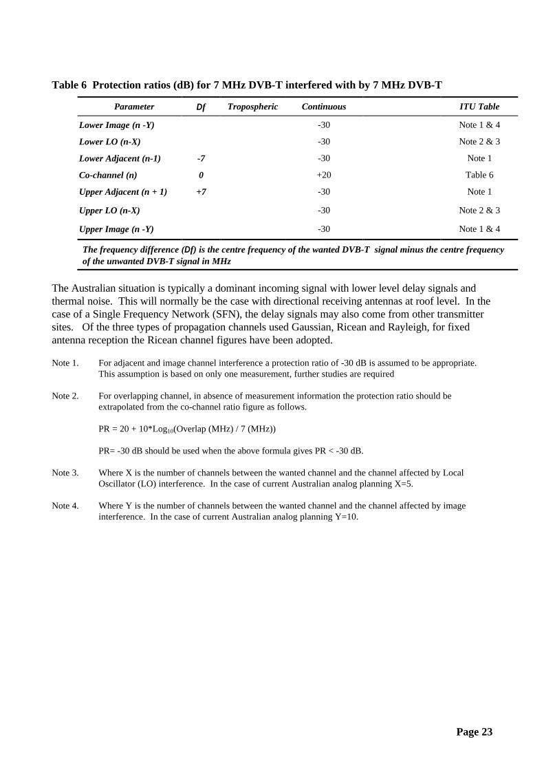
Table 6 Protection ratios (dB) for 7 MHz DVB-T interfered with by 7 MHz DVB-T
Parameter ∆ f Tropospheric Continuous ITU Table
Lower Image (n -Y) -30 Note 1 & 4
Lower LO (n-X) -30 Note 2 & 3
Lower Adjacent (n-1) -7 -30 Note 1
Co-channel (n) 0 +20 Table 6
Upper Adjacent (n + 1) +7 -30 Note 1
Upper LO (n-X) -30 Note 2 & 3
Upper Image (n -Y) -30 Note 1 & 4
The frequency difference (∆ f) is the centre frequency of the wanted DVB-T signal minus the centre frequencyof the unwanted DVB-T signal in MHz
The Australian situation is typically a dominant incoming signal with lower level delay signals andthermal noise. This will normally be the case with directional receiving antennas at roof level. In thecase of a Single Frequency Network (SFN), the delay signals may also come from other transmittersites. Of the three types of propagation channels used Gaussian, Ricean and Rayleigh, for fixedantenna reception the Ricean channel figures have been adopted.
Note 1. For adjacent and image channel interference a protection ratio of -30 dB is assumed to be appropriate.This assumption is based on only one measurement, further studies are required
Note 2. For overlapping channel, in absence of measurement information the protection ratio should beextrapolated from the co-channel ratio figure as follows.
PR = 20 + 10*Log10(Overlap (MHz) / 7 (MHz))
PR= -30 dB should be used when the above formula gives PR < -30 dB.
Note 3. Where X is the number of channels between the wanted channel and the channel affected by LocalOscillator (LO) interference. In the case of current Australian analog planning X=5.
Note 4. Where Y is the number of channels between the wanted channel and the channel affected by imageinterference. In the case of current Australian analog planning Y=10.

Page 24
Table 7 Co-channel protection ratios (dB) for 7 MHz DVB-T interfered with by overlappingPAL B signal including sound
Parameter ∆ f Tropospheric Continuous ITU Table
Lower Adjacent (n-1) -9.25 -35/-37 Table 10/16
-8.75 -14 Table 16
-8.25 -8 Table 16
-7.75 -4 Table 16
-6.25 -2 Table 16
-3.45 +1 Table 16
-3.25 +3 Table 16
Co-channel (n) -2.25 +3 Table 8/16
-1.25 +3 Table 16
1.75 +2 Table 16
2.75 -1 Table 16
4.25 -29 Table 16
Upper Adjacent (n + 1) 4.75 -38/-36 Table 12/16
LO Channel (n + 5)
Image Channel (n+10) -46 dB Table 14
The frequency difference (∆ f) is the vision carrier of the analog television signal minus the centre frequency ofthe DVB-T signal in MHz
Table 8 Co-channel protection ratios (dB) for 7 MHz DVB-T interfered with by CW or a FMcarrier
Parameter ∆ f Tropospheric Continuous ITU Table
Frequency Difference -10.5 -38 Table 18
-4 -33 Table 18
-3.4 -3 Table 18
0 -3 Table 18
3.4 -3 Table 18
4 -33 Table 18
10.5 -38 Table 18
The frequency difference (∆ f) is the FM carrier frequency minus the centre frequency of the DVB-T signal inMHz
Page 25
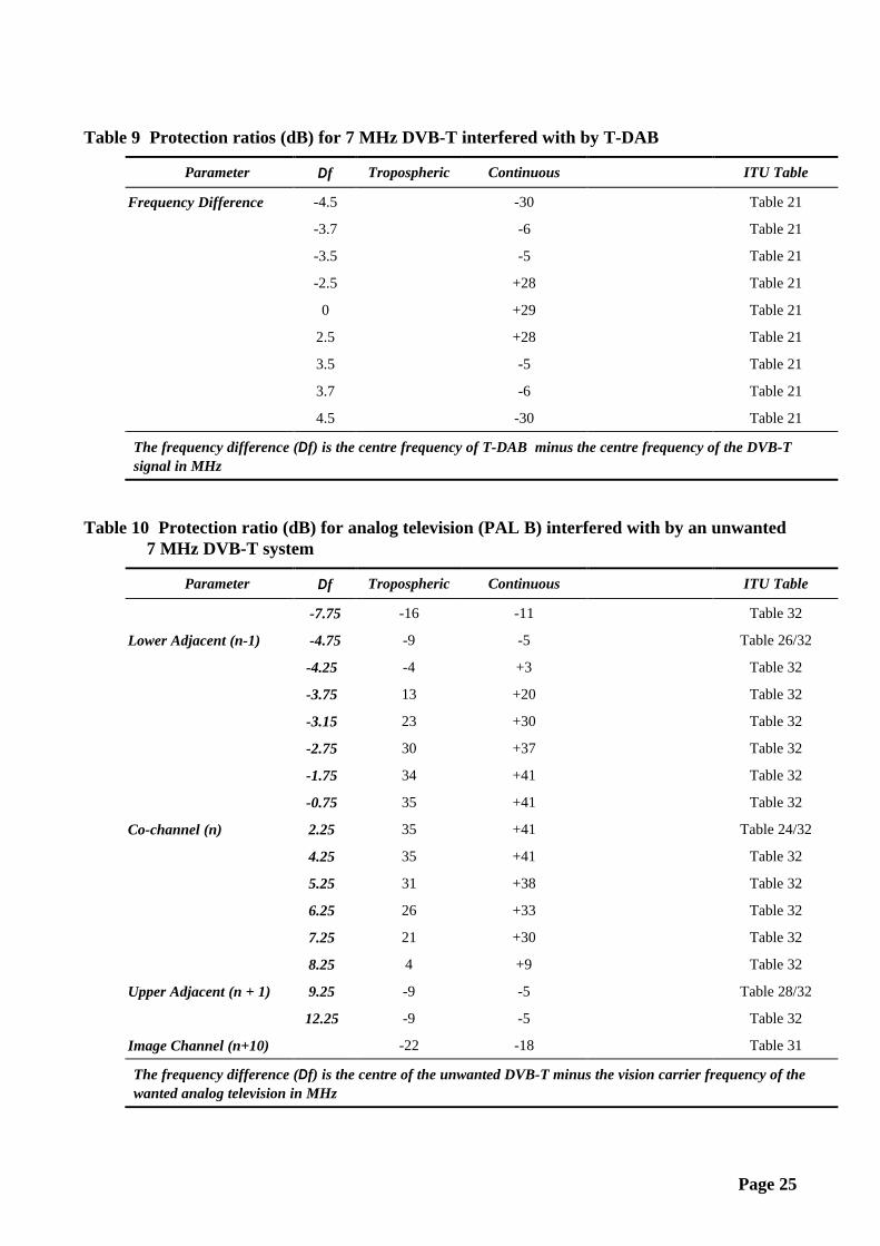
Table 9 Protection ratios (dB) for 7 MHz DVB-T interfered with by T-DAB
Parameter ∆ f Tropospheric Continuous ITU Table
Frequency Difference -4.5 -30 Table 21
-3.7 -6 Table 21
-3.5 -5 Table 21
-2.5 +28 Table 21
0 +29 Table 21
2.5 +28 Table 21
3.5 -5 Table 21
3.7 -6 Table 21
4.5 -30 Table 21
The frequency difference (∆ f) is the centre frequency of T-DAB minus the centre frequency of the DVB-Tsignal in MHz
Table 10 Protection ratio (dB) for analog television (PAL B) interfered with by an unwanted7 MHz DVB-T system
Parameter ∆ f Tropospheric Continuous ITU Table
-7.75 -16 -11 Table 32
Lower Adjacent (n-1) -4.75 -9 -5 Table 26/32
-4.25 -4 +3 Table 32
-3.75 13 +20 Table 32
-3.15 23 +30 Table 32
-2.75 30 +37 Table 32
-1.75 34 +41 Table 32
-0.75 35 +41 Table 32
Co-channel (n) 2.25 35 +41 Table 24/32
4.25 35 +41 Table 32
5.25 31 +38 Table 32
6.25 26 +33 Table 32
7.25 21 +30 Table 32
8.25 4 +9 Table 32
Upper Adjacent (n + 1) 9.25 -9 -5 Table 28/32
12.25 -9 -5 Table 32
Image Channel (n+10) -22 -18 Table 31
The frequency difference (∆ f) is the centre of the unwanted DVB-T minus the vision carrier frequency of thewanted analog television in MHz

Page 26
Table 11 Protection ratios (dB) for wanted FM sound interfered with by an overlapping7 MHz DVB-T
Parameter ∆ f Tropospheric Continuous Chester Report ITU Table
FM Sound -5 0 +9 Table A1.35
-3.7 0 +9 Table A1.35
-3.5 5 +14 Table A1.35
-3 6 +16 Table A1.35
0 6 +16 Table A1.35 Table 34
3 5 +15 Table A1.35
3.5 3 +12 Table A1.35
3.7 -17 -11 Table A1.35
> 4.0 < -32 < -27 Table A1.35
The frequency difference (∆ f) is the centre of the digital radio carrier frequency minus the centre frequency ofthe DVB-T signal in MHz
Table 12 Protection ratios (dB) for T-DAB interfered with by 7 MHz DVB-T
Parameter ∆ f Tropospheric Continuous Chester Report ITU Table
Terrestrial DAB -4.5 -49 Table A1.39
-3.7 0 Table A1.39
-3.5 +1 Table A1.39
-2.5 +2 Table A1.39
0 +2 Table A1.39
2.5 +2 Table A1.39
3.5 +1 Table A1.39
3.7 +0 Table A1.39
4.5 -49 Table A1.39
The frequency difference (∆ f) is the centre of DVB-T minus the centre frequency of T-DAB in MHz

Page 27
APPENDIX 4
MODULATION SCHEMES
Table 13 Net data rates in the DVB-T 7 MHz system (in Mbits/s)
Modulation Code Rate Guard Interval
5.90625 Ms/s 1/4 1/8 1/16 1/32QPSK 1/2 4.354 4.838 5.123 5.278
2/3 5.806 6.451 6.830 7.0373/4 6.532 7.257 7.684 7.9175/6 7.257 8.064 8.538 8.7977/8 7.62 8.467 8.965 9.237
16-QAM 1/2 8.709 9.676 10.246 10.5562/3 11.612 12.902 13.661 14.0753/4 13.063 14.515 15.369 15.8345/6 14.515 16.127 17.076 17.5947/8 15.240 16.934 17.930 18.473
64-QAM 1/2 13.063 14.515 15.369 15.8342/3 17.418 19.353 20.491 21.1123/4 19.595 21.772 23.053 23.7515/6 21.772 24.191 25.614 26.3907/8 22.861 25.401 26.895 27.710
Guard Time:(µsec)
“2K” 64 32 16 8
“8K” 256 128 64 32
The net bit rates increase with higher code rates of the inner error protection, short guard intervalsand higher stages of sub carrier modulation. The higher data rate can only be achieved by decreasingthe amount of error protection.
Figure 3
1 / 2 2 / 3 3 / 4 5 / 6 7 / 81 / 2 2 / 3 3 / 4 5 / 6 7 / 8
1 / 2 2 / 3 3 / 4 5 / 6 7 / 8
1 / 4
1 / 8
1 / 1 6
1 / 3 20
5
10
15
20
25
30
Net
dat
a ra
te [
Mbi
t/s]
Modulation & Code Rate
Guard Interval
Net data rates in the DVB-T 7 MHz system
QPSK16-QAM
64-QAM

Page 28
REFERENCE DOCUMENTATION
Planning Criteria for Digital Terrestrial Television Services in the VHF/UHF Bands - DraftRevision of Recommendation ITU-R BT.1368, Document 11/22-E, ITU Radiocommunication StudyGroups, 14 April 1998
Terrestrial Digital Television Planning and Implementation Considerations, Document BPN 005Second Issue, European Broadcasting Union, July 1997
Chester 1997 Multilateral Coordination Agreement relating to Technical Criteria, CoordinationPrinciples and Procedure for the introduction of Terrestrial Digital Video Broadcasting (DVB-T),European Radiocommunications Office, July 1997
Laboratory Testing of DTTB Modulation Systems, Department of Communications and the Arts,Laboratory Report 98/01, April 1998.
Interim Australian Broadcasting Planning Handbook, Australian Broadcasting Authority, August1995
Technical Planning Guidelines, Australian Broadcasting Authority, August 1995
Australian Radiofrequency Spectrum Plan, Spectrum Management Agency, January 1997.

Page 29
WEBSITES
Australian Broadcasting Authority www.aba.gov.au
Australian Communications Authority www.aca.gov.au
British Broadcasting Corporation www.bbc.co.uk
Communication Research Centre www.drb.crc.doc.ca
Communications Laboratory www.commslab.gov.au
Digital Video Broadcasting www.dvb.org
European Broadcasting Union www.ebu.ch
European Radiocommunications Office www.ero.dk
International Telecommunication Union www.itu.int
MapInfo Decibel Planner www.mapinfo.com.au
National Transmission Agency www.dca.gov.au