australia germany portfolio - f1inschools.de · through the pit display, portfolio, team uniforms,...
TRANSCRIPT
PORTFOLIOWORLd FInaLs 2012
C O L L a b O R a T I O n T e a m
ausTRaLIa geRmany
Team Name
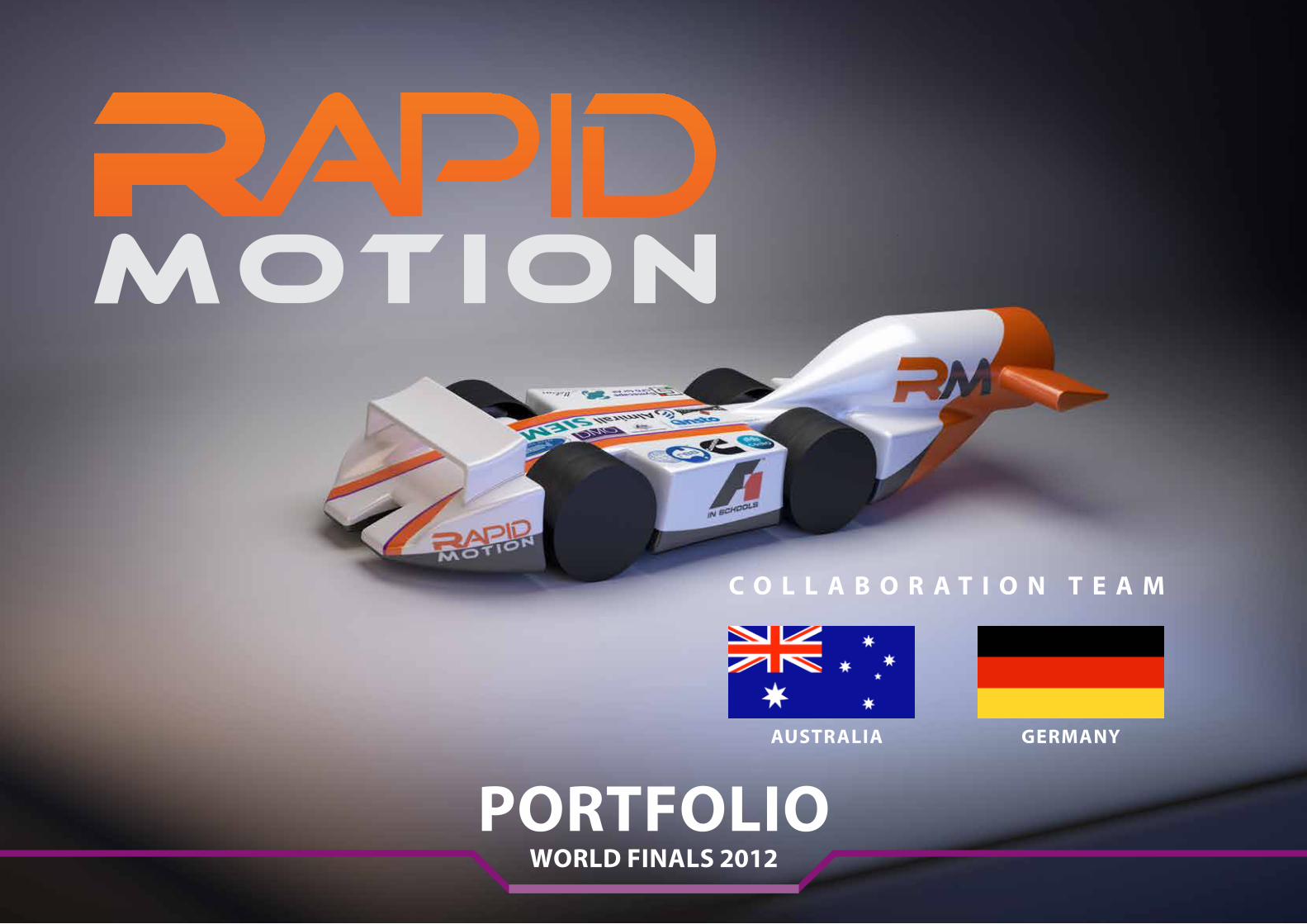
To symbolise the collaborative nature of our team, the name ‘Rapid Motion’ is derived from a combination of our national team names. Originally known as ‘Rapid Racing’ from Australia and ‘Motion Blur’ from Germany.
Team Goal
Put simply and ambitiously, our goal is to be the first collaboration team to win the World Finals in Abu Dhabi.
Team moTTo
Our motto - “Unleash Potential” was chosen because we believe that with collaboration and commitment, innovation and imagination, and a positive attitude, team ‘Rapid Motion’ will unleash its potential energy on the world stage.
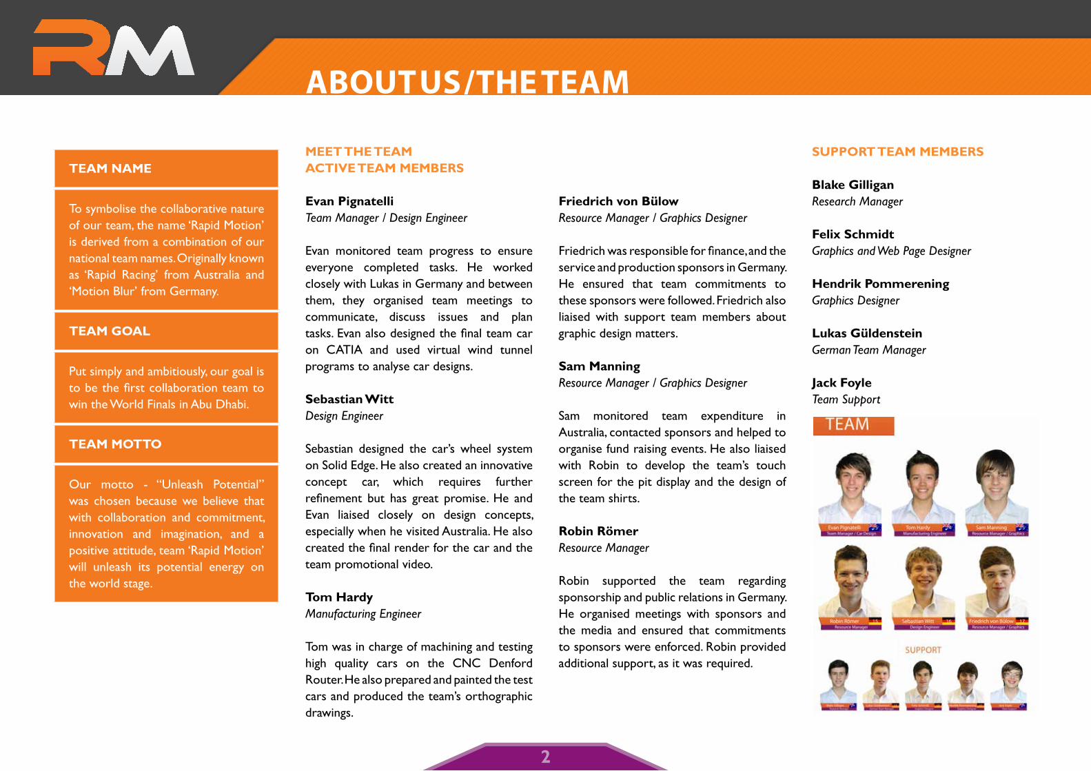
meeT The TeamacTive Team members
evan Pignatelli Team Manager / Design Engineer
Evan monitored team progress to ensure everyone completed tasks. He worked closely with Lukas in Germany and between them, they organised team meetings to communicate, discuss issues and plan tasks. Evan also designed the final team car on CATIA and used virtual wind tunnel programs to analyse car designs.
sebastian Witt Design Engineer
Sebastian designed the car’s wheel system on Solid Edge. He also created an innovative concept car, which requires further refinement but has great promise. He and Evan liaised closely on design concepts, especially when he visited Australia. He also created the final render for the car and the team promotional video.
Tom hardyManufacturing Engineer
Tom was in charge of machining and testing high quality cars on the CNC Denford Router. He also prepared and painted the test cars and produced the team’s orthographic drawings.
Friedrich von bülowResource Manager / Graphics Designer
Friedrich was responsible for finance, and the service and production sponsors in Germany. He ensured that team commitments to these sponsors were followed. Friedrich also liaised with support team members about graphic design matters.
sam manningResource Manager / Graphics Designer
Sam monitored team expenditure in Australia, contacted sponsors and helped to organise fund raising events. He also liaised with Robin to develop the team’s touch screen for the pit display and the design of the team shirts.
robin römerResource Manager
Robin supported the team regarding sponsorship and public relations in Germany. He organised meetings with sponsors and the media and ensured that commitments to sponsors were enforced. Robin provided additional support, as it was required.
suPPorT Team members
blake Gilligan Research Manager
Felix schmidt Graphics and Web Page Designer
hendrik PommereningGraphics Designer
lukas GüldensteinGerman Team Manager
Jack FoyleTeam Support
2
abOuT us / The Team
raPid raciNG
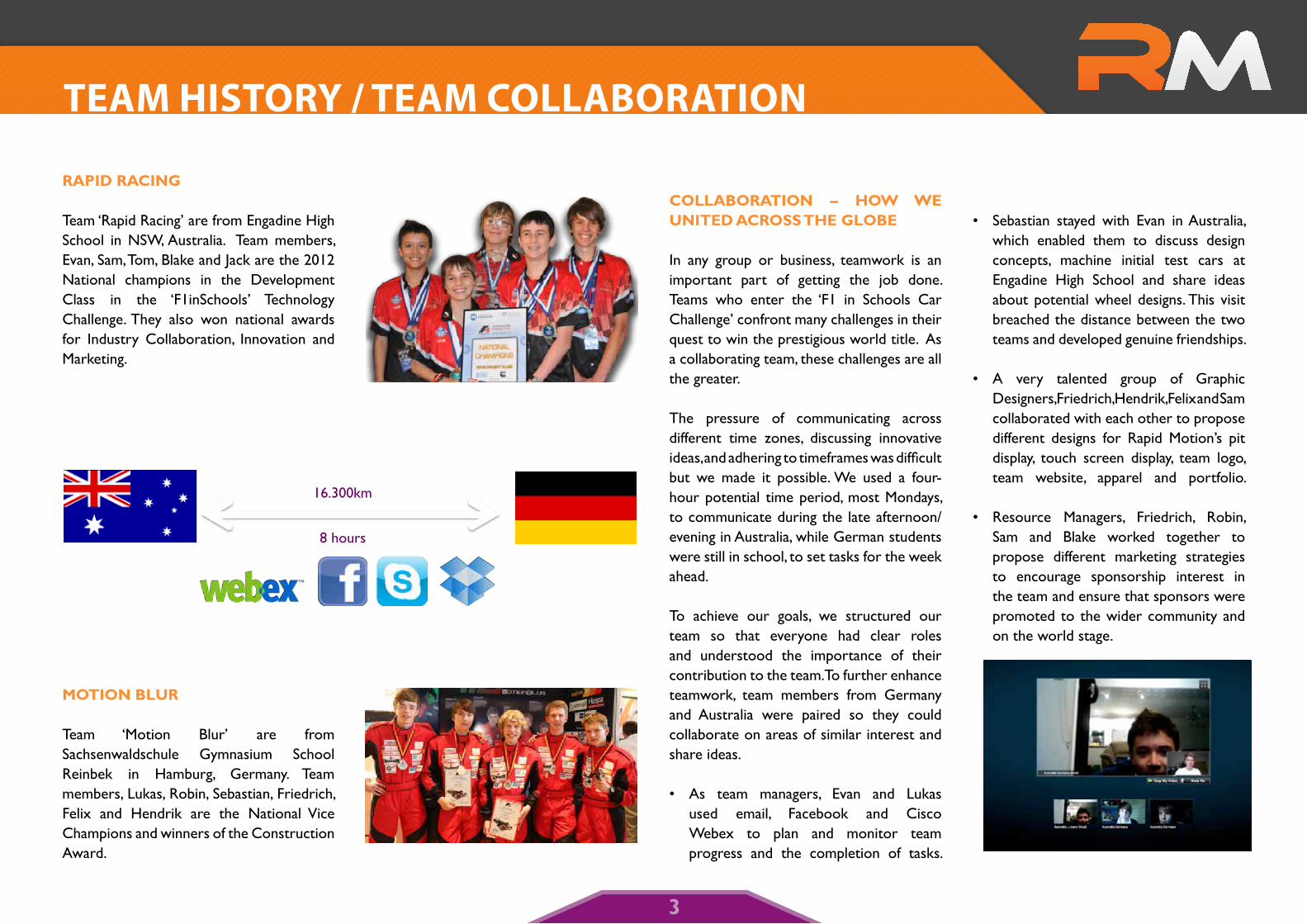
Team ‘Rapid Racing’ are from Engadine High School in NSW, Australia. Team members, Evan, Sam, Tom, Blake and Jack are the 2012 National champions in the Development Class in the ‘F1inSchools’ Technology Challenge. They also won national awards for Industry Collaboration, Innovation and Marketing.
moTioN blur
Team ‘Motion Blur’ are from Sachsenwaldschule Gymnasium School Reinbek in Hamburg, Germany. Team members, Lukas, Robin, Sebastian, Friedrich, Felix and Hendrik are the National Vice Champions and winners of the Construction Award.
collaboraTioN – hoW We uNiTed across The Globe
In any group or business, teamwork is an important part of getting the job done. Teams who enter the ‘F1 in Schools Car Challenge’ confront many challenges in their quest to win the prestigious world title. As a collaborating team, these challenges are all the greater.
The pressure of communicating across different time zones, discussing innovative ideas, and adhering to timeframes was difficult but we made it possible. We used a four-hour potential time period, most Mondays, to communicate during the late afternoon/evening in Australia, while German students were still in school, to set tasks for the week ahead.
To achieve our goals, we structured our team so that everyone had clear roles and understood the importance of their contribution to the team. To further enhance teamwork, team members from Germany and Australia were paired so they could collaborate on areas of similar interest and share ideas.
• As team managers, Evan and Lukas used email, Facebook and Cisco Webex to plan and monitor team progress and the completion of tasks.
• Sebastian stayed with Evan in Australia, which enabled them to discuss design concepts, machine initial test cars at Engadine High School and share ideas about potential wheel designs. This visit breached the distance between the two teams and developed genuine friendships.
• A very talented group of Graphic Designers, Friedrich, Hendrik, Felix and Sam collaborated with each other to propose different designs for Rapid Motion’s pit display, touch screen display, team logo, team website, apparel and portfolio.
• Resource Managers, Friedrich, Robin, Sam and Blake worked together to propose different marketing strategies to encourage sponsorship interest in the team and ensure that sponsors were promoted to the wider community and on the world stage.
Team hIsTORy / Team COLLabORaTIOn
16.300km
8 hours
3
corPoraTe ideNTiTy
Attention to detail is evident in the way in which we established our corporate identity from the start. Our team web page, www.teamrapidmotion.com, clearly specifies team colours and acceptable fonts and logos to be used on light or dark backgrounds. This screen shot is an example of the team colours that are consistently promoted through the pit display, portfolio, team uniforms, marketing and the team car.
Team loGo
Our logo is simple yet distinctive and effective to encourage spectators and competitors
to remember our name. Our logo highlights our name Rapid Motion, and is also available as an acronym. The bright orange ‘R’ and the dark grey ‘M’ represent our primary team colours. The logo was designed to look sleek and represent a racetrack, as shown by the curved letters.
Team car ideNTiTy
Consistent with other applications of our corporate identity, our final car render closely reflects team colours - predominantly white and orange with a hint of grey and purple. Decal stencils were used for graphics.
Team uNiForms
competition uniform
Our competition uniforms were designed around three main factors – eye-catching, comfort, and climate. The shirts are made of polyester, which provides maximum comfort and no itch. The design promotes our team colours, predominately orange, to stand out in the crowd.
Competition shirts are split into two categories – ‘Active’ and ‘Support’. As a team, we wanted all team members from both countries to be recognised as members of Rapid Motion, so our shirt designs are similar but different. Members of the team who compete in Abu Dhabi will wear the ‘Active’ design; and team members who provide support will wear the ‘Support’ design.
Team pants are black and these were donated to us from ‘5.11 Tactical Series’ clothing. They are high quality pants and are worn by large police networks around the world such as the FBI, New York, L.A and Australian Police.
casual uniform
‘5.11 Tactical Series’ also supplied the team’s casual uniform, which can double for formal occasions. Our logo has been branded into the shirts so that our team is identifiable in public. These clothes are comfortable and give our team a professional look.
Team IdenTITy
4
ProJecT maNaGemeNT
An effective project management strategy was developed to manage the constraints of communicating in different time zones; the range of resources available to both teams; the scope of the task; and the fact that our two teams included students with a variety of knowledge and skills.
Our new team structure identified the special talents of members from both Australia and Germany and integrated these abilities into the collaborative team, ‘Rapid Motion’. To help achieve our aim to win the world title, we used a program called Wunderkit, which allowed us to assign tasks and effectively manage time, scope, budget and the challenge of international communication.
scoPe
At the start of our campaign for the ‘F1 in Schools World Finals’, Australia and Germany organised a team meeting over Cisco WebEx with all team members. We held this meeting to scope the task ahead and discuss the positives, negatives and issues (PNI) including timelines, budgets, roles and responsibilities, marketing strategies, resources, risks and opportunities for collaboration.
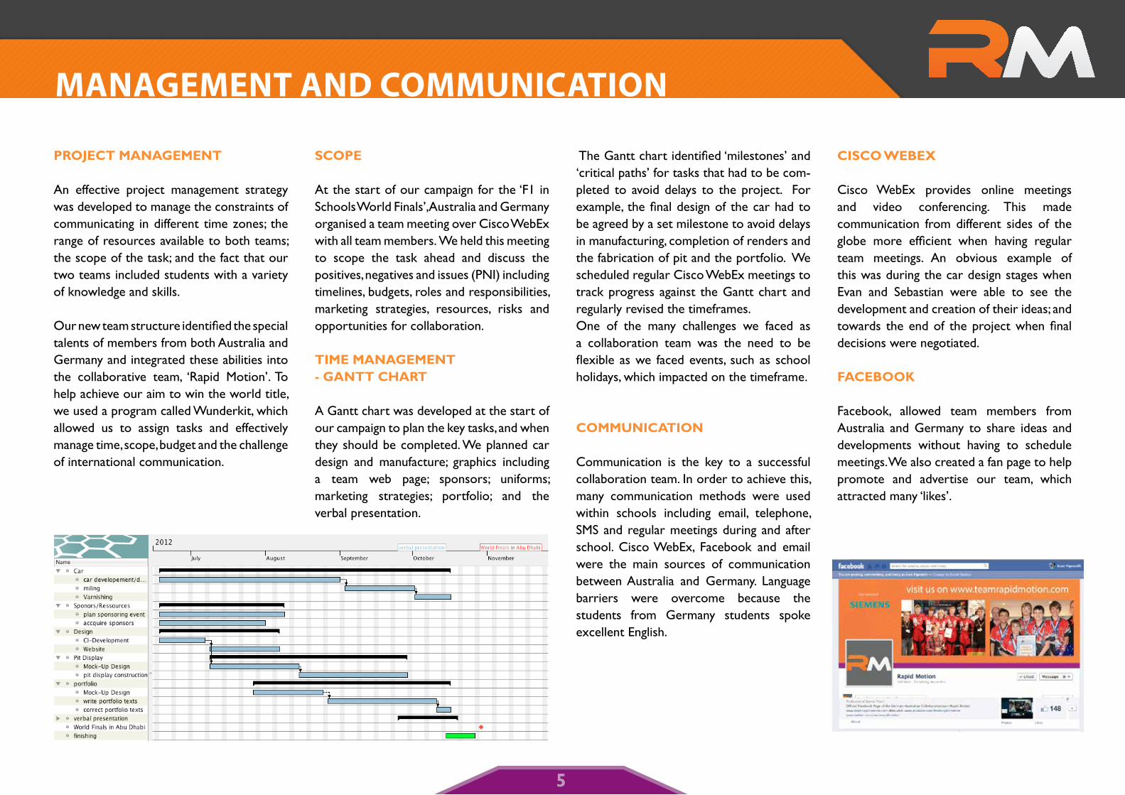
Time maNaGemeNT - GaNTT charT
A Gantt chart was developed at the start of our campaign to plan the key tasks, and when they should be completed. We planned car design and manufacture; graphics including a team web page; sponsors; uniforms; marketing strategies; portfolio; and the verbal presentation.
The Gantt chart identified ‘milestones’ and ‘critical paths’ for tasks that had to be com-pleted to avoid delays to the project. For example, the final design of the car had to be agreed by a set milestone to avoid delays in manufacturing, completion of renders and the fabrication of pit and the portfolio. We scheduled regular Cisco WebEx meetings to track progress against the Gantt chart and regularly revised the timeframes. One of the many challenges we faced as a collaboration team was the need to be flexible as we faced events, such as school holidays, which impacted on the timeframe.
commuNicaTioN
Communication is the key to a successful collaboration team. In order to achieve this, many communication methods were used within schools including email, telephone, SMS and regular meetings during and after school. Cisco WebEx, Facebook and email were the main sources of communication between Australia and Germany. Language barriers were overcome because the students from Germany students spoke excellent English.
cisco Webex
Cisco WebEx provides online meetings and video conferencing. This made communication from different sides of the globe more efficient when having regular team meetings. An obvious example of this was during the car design stages when Evan and Sebastian were able to see the development and creation of their ideas; and towards the end of the project when final decisions were negotiated.
Facebook, allowed team members from Australia and Germany to share ideas and developments without having to schedule meetings. We also created a fan page to help promote and advertise our team, which attracted many ‘likes’.
Team IdenTITymanagemenT and COmmunICaTIOn
5
managemenT
resources (FiNaNce maNaGemeNT)
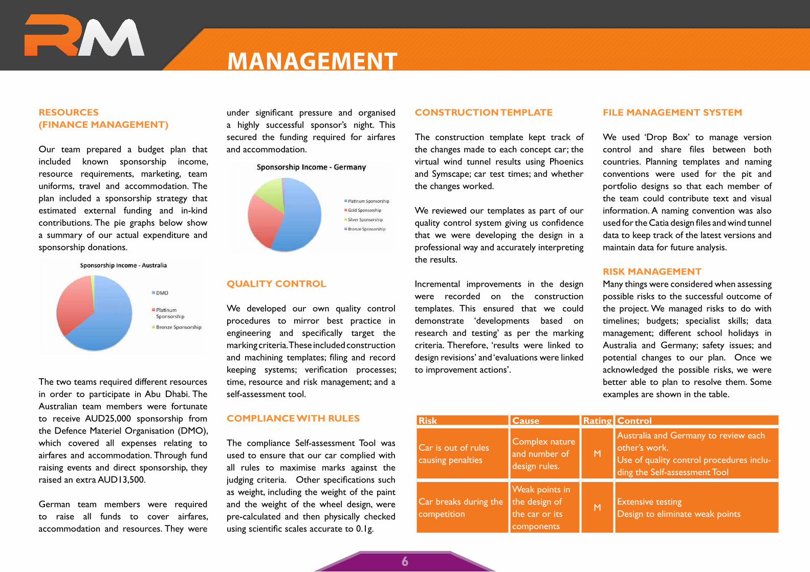
Our team prepared a budget plan that included known sponsorship income, resource requirements, marketing, team uniforms, travel and accommodation. The plan included a sponsorship strategy that estimated external funding and in-kind contributions. The pie graphs below show a summary of our actual expenditure and sponsorship donations.
The two teams required different resources in order to participate in Abu Dhabi. The Australian team members were fortunate to receive AUD25,000 sponsorship from the Defence Materiel Organisation (DMO), which covered all expenses relating to airfares and accommodation. Through fund raising events and direct sponsorship, they raised an extra AUD13,500.
German team members were required to raise all funds to cover airfares, accommodation and resources. They were
under significant pressure and organised a highly successful sponsor’s night. This secured the funding required for airfares and accommodation.
QualiTy coNTrol
We developed our own quality control procedures to mirror best practice in engineering and specifically target the marking criteria. These included construction and machining templates; filing and record keeping systems; verification processes; time, resource and risk management; and a self-assessment tool.
comPliaNce WiTh rules
The compliance Self-assessment Tool was used to ensure that our car complied with all rules to maximise marks against the judging criteria. Other specifications such as weight, including the weight of the paint and the weight of the wheel design, were pre-calculated and then physically checked using scientific scales accurate to 0.1g.
coNsTrucTioN TemPlaTe
The construction template kept track of the changes made to each concept car; the virtual wind tunnel results using Phoenics and Symscape; car test times; and whether the changes worked.
We reviewed our templates as part of our quality control system giving us confidence that we were developing the design in a professional way and accurately interpreting the results.
Incremental improvements in the design were recorded on the construction templates. This ensured that we could demonstrate ‘developments based on research and testing’ as per the marking criteria. Therefore, ‘results were linked to design revisions’ and ‘evaluations were linked to improvement actions’.
File maNaGemeNT sysTem
We used ‘Drop Box’ to manage version control and share files between both countries. Planning templates and naming conventions were used for the pit and portfolio designs so that each member of the team could contribute text and visual information. A naming convention was also used for the Catia design files and wind tunnel data to keep track of the latest versions and maintain data for future analysis.
risk maNaGemeNTMany things were considered when assessing possible risks to the successful outcome of the project. We managed risks to do with timelines; budgets; specialist skills; data management; different school holidays in Australia and Germany; safety issues; and potential changes to our plan. Once we acknowledged the possible risks, we were better able to plan to resolve them. Some examples are shown in the table.
risk cause rating control
Car is out of rules causing penalties
Complex nature and number of design rules.
M
Australia and Germany to review each other’s work. Use of quality control procedures inclu-ding the Self-assessment Tool
Car breaks during the competition
Weak points in the design of the car or its components
MExtensive testing Design to eliminate weak points
6
PiT disPlay
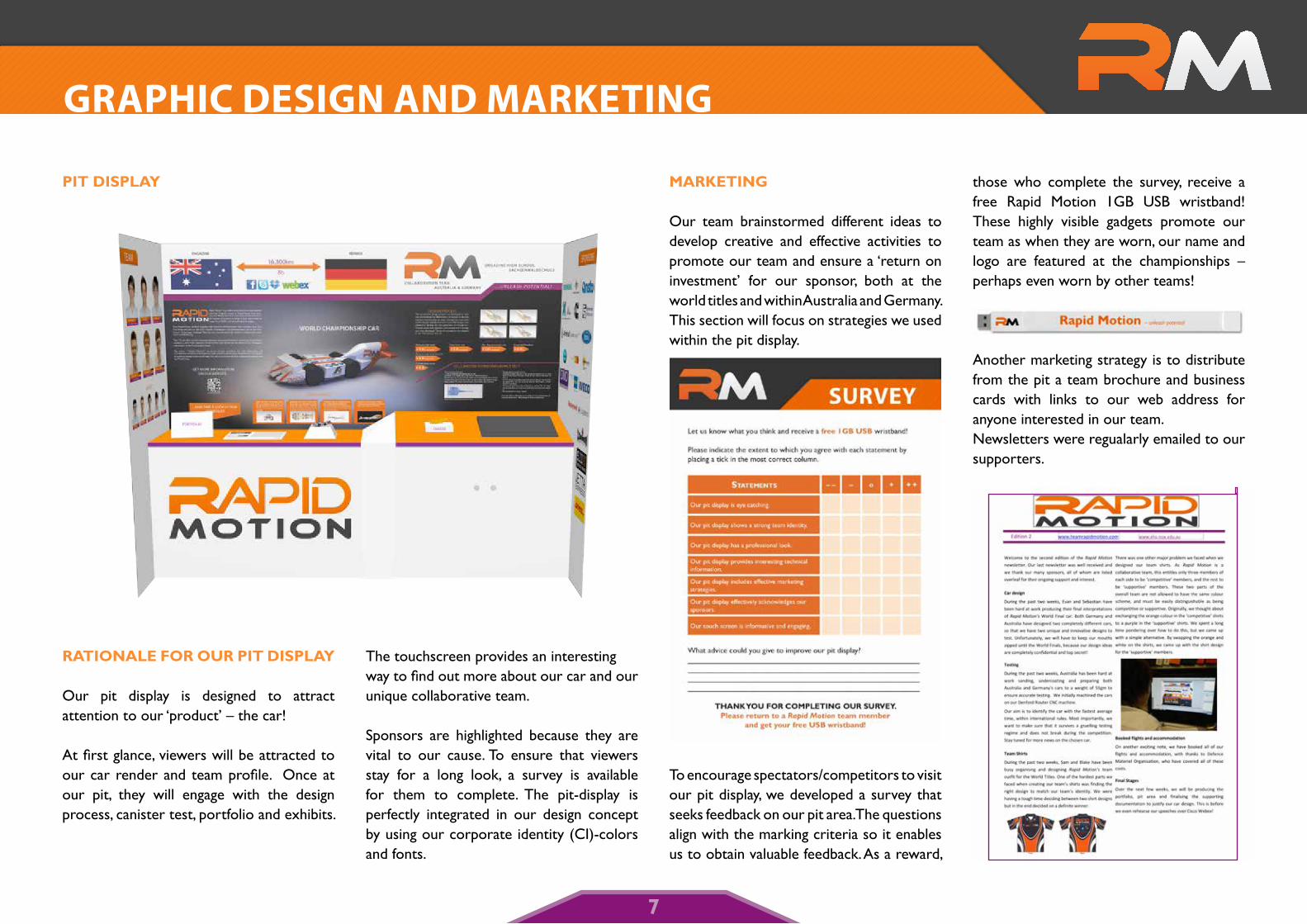
raTioNale For our PiT disPlay
Our pit display is designed to attract attention to our ‘product’ – the car!
At first glance, viewers will be attracted to our car render and team profile. Once at our pit, they will engage with the design process, canister test, portfolio and exhibits.
The touchscreen provides an interesting way to find out more about our car and our unique collaborative team.
Sponsors are highlighted because they are vital to our cause. To ensure that viewers stay for a long look, a survey is available for them to complete. The pit-display is perfectly integrated in our design concept by using our corporate identity (CI)-colors and fonts.
markeTiNG
Our team brainstormed different ideas to develop creative and effective activities to promote our team and ensure a ‘return on investment’ for our sponsor, both at the world titles and within Australia and Germany. This section will focus on strategies we used within the pit display.
To encourage spectators/competitors to visit our pit display, we developed a survey that seeks feedback on our pit area. The questions align with the marking criteria so it enables us to obtain valuable feedback. As a reward,
those who complete the survey, receive a free Rapid Motion 1GB USB wristband! These highly visible gadgets promote our team as when they are worn, our name and logo are featured at the championships – perhaps even worn by other teams!
Another marketing strategy is to distribute from the pit a team brochure and business cards with links to our web address for anyone interested in our team. Newsletters were regualarly emailed to our supporters.
gRaPhIC desIgn and maRkeTIng
7
NeWsPaPers
Newspapers in both Australia and Germany have printed articles about the ‘F1 in Schools’ program and the achievements of Rapid Racing, Motion Blur and Rapid Motion. This has generated interest in the program, our schools and ultimately, from our sponsors.
TelevisioN broadcasT
Within Australia, Channel 10 News ran a story on Rapid Racing which attracted a great deal of attention as evidenced by the hits on our webpage where a link was created. Within Germany, Rapid Motion also held a press conference, which generated interest in a highly successful Sponsors’ Night.
FuNd raisiNG eveNTs
Interest and funds were also raised by hosting barbeques at local shops, including Woolworths and Bunnings in Australia. These events are advantageous as they provide opportunities to display the car, discuss the competition, promote our school and raise money. Events like these really boosted our spirits as it is great to know that other people are interested in what we are doing.
WebsiTes / social NeTWorkiNG
Our website, located at www.teamrapidmotion.com has links to Twitter, You Tube and Facebook, where we have attracted many ‘likes’. All sponsors are promoted on the site, which is regularly updated. This is also connected to our school websites, and school newsletters, thus expanding the reach of the ‘F1 in Schools Challenge’.
suPPorTiNG sPoNsors ThrouGh PromoTioN
Within Australia, the international company ‘5.11 Tactical Series’ clothing company held a grand opening of one of its 91 global stores. This company supplies all uniforms for military and police forces including FBI and Australian forces. The “boss” of the organisation visited Australia for the event and the Australian component of the team was asked to set up the track and supervise car racing for families. This was a highly popular activity and generated huge interest in the many participants. It also led to further sponsorship for the team.
PoliTical suPPorT
The local representative from NSW State Parliament, Hon. Mr Lee Evans, delivered a speech on our achievements in the NSW Parliament, which is now part of the official
historical record. Additionally, he wrote about our team in a newsletter that was sent to thousands of constituents in his seat.
securiNG sPoNsorshiP
Both schools developed a ‘Sponsorship Proposal’ outlining sponsorship for bronze, silver, gold and platinum levels. Initial contact was made through letters, phone calls and emails that included details of our program and proposal. We also visited several sponsors and presented to board meetings to generate interest and support. A Commercial Register in Germany was used to give us contacts with businesses that may have had an interest in F1 in Schools.
sPoNsors are a ParT oF our Team!
We believe that a personal touch is important so that sponsors feel a part of the Rapid Motion family. They were kept informed about our progress through a series of newsletters, which were emailed to sponsors with photographs and updates, including each sponsor’s logo. Students from Germany also held a highly successful sponsors night
where they demonstrated the racetrack and brought all of their sponsors together. We acknowledge Nordmetall Cup Formel 1 who supported Germany with the track many times and also milled some testing cars. Sponsors celebrated our successes and are excited by our achievements; and importantly, they want to stay connected with ‘F1 in Schools’ in the future.
eNsuriNG sPoNsors‘ reTurN oN Their iNvesTmeNT
The free Rapid Motion USB wristbands also contain a file with descriptions of our platinum and gold sponsors and hyperlinks to their websites. This was an effective way to recognise and promote our sponsors to the wider community. Additionally, all sponsors are recognised on the website. And we included their preferred position of their logos and liaised with them regarding social media.
PROmOTIOn/sPOnsORs
8
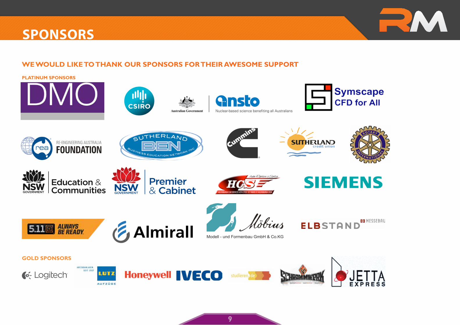
We Would like To ThaNk our sPoNsors For Their aWesome suPPorT
PlaTiNum sPoNsors
Gold sPoNsors
sPOnsORs
9

commuNicaTioN skills collaboraTioN
We presented to the marketing team from 5.11 Tactical Series and Enagdine Rotary. A presentation to engineers and scientists at ANSTO, as shown in the image to the right. We received constructive advice regarding communication skills and presentation skills.
iNdusTry collaboraTioN
Australian Nuclear Science and Technology Organisation (ANSTO) provided a range of support for the team. Initially, Dr Michael Zettinig, (Strategic Events and Partnership Advisor Government, International and External Relations) liaised with team members to offer financial support. This was followed with an opportunity for the Australian part of the team plus Sebastian, who was visiting Australia at the time, to meet with a team of scientists and engineers from ANSTO. This was an incredible opportunity as we did a presentation about our car and possible design options for the future. Dr Lyndon Edwards, Head, Institute for Materials Engineering and his team discussed possible design options and materials that might be considered in future. They also offered to machine test wheels and maintain links with Engadine High School for other teams. Alan Ng, from CSIRO provided technical advice regarding car components.
In October 2012, the Australian part of Rapid Motion was asked to present at the ‘Southern Strength Agile Manufacturing Network’ breakfast. This encouraged industry involvement in the ‘F1 in Schools Challenge’ and has generated promising support and sharing of industry expertise into the future.
We were fortunate to develop a close collaboration with Mobius in Germany. We met with them on five separate occasions to discuss the best approach to machining our World Final car. They shared their expertise about milling our car without telling us what
to do. We provided them with CAD data and they turned this into CAM codes, and made suggestions about the final decisions we could make to machine the car. They also machined our wheels and provided advice on machining.
Our collaboration with businesses that manufactured and painted our car was highly successful. Our relationship allowed us to develop a better understanding of the machining process of the car body; the wheels and the quality control that is necessary to achieve a fantastic product.
icT collaboraTioN
We collaborated with Rick from Invenio who taught us new elements of the CATIA program after the National Championships.
Technical Support Officer, Sean Sparks, in-creased Sam’s knowledge of web design and provided guidance on Dreamweaver for our touch screen display.
Graphic design skills are a special talent of team members so a great deal of experti-se was shared among team members from Germany and Australia.
educaTioNal collaboraTioN
Brian Milton, a Professor of Mechanical Engineering University of NSW (retired), helped us to understand the forces on the car and the variables that we could control. He advised us about aeronautical and force theories and verified the direction we were taking with the shape of the car.
COLLabORaTIOn
10
WhaT makes a FasT car?
To understand the variables that affect the straight-line performance of an F1 car, we need to have an appreciation of physics, the forces that propel the car and the reactive forces that slow it down. We undertook an analysis of these forces to develop design concepts. We considered the following forces and the extent to which they could be controlled by our design:
• The thrust that propels the car forward, and where it is applied;
• The reactive drag force;• Skin friction and rolling resistance.
ThrusT
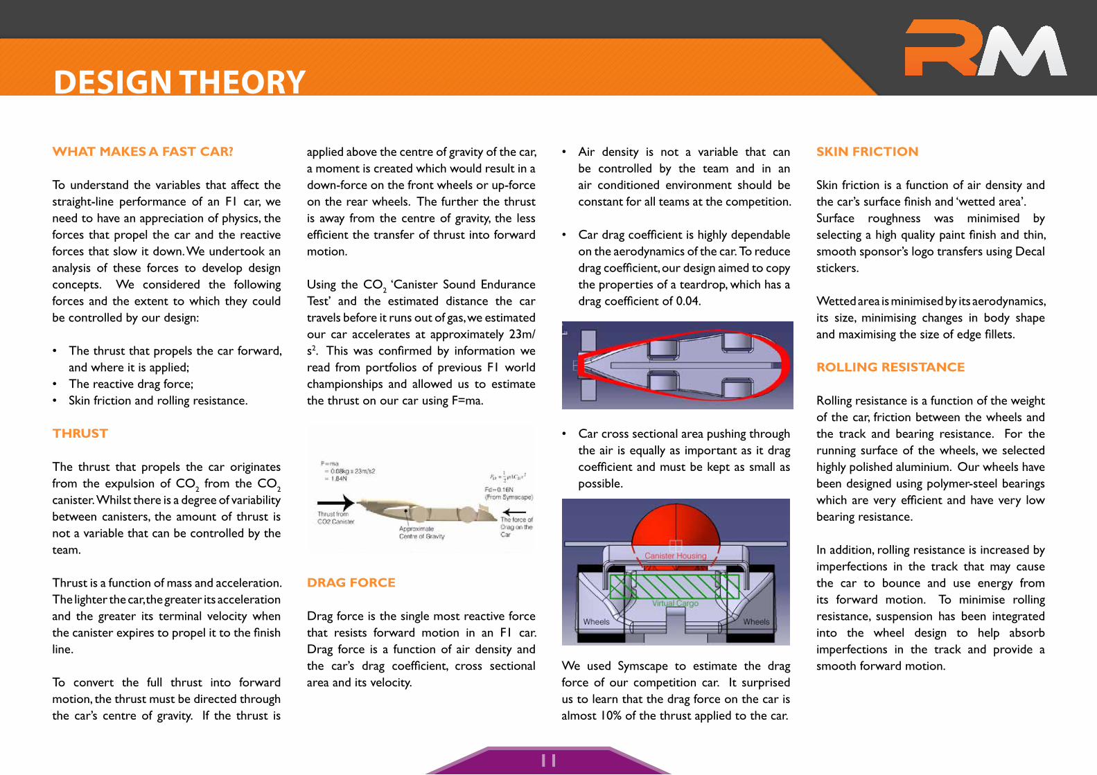
The thrust that propels the car originates from the expulsion of CO2 from the CO2 canister. Whilst there is a degree of variability between canisters, the amount of thrust is not a variable that can be controlled by the team.
Thrust is a function of mass and acceleration. The lighter the car, the greater its acceleration and the greater its terminal velocity when the canister expires to propel it to the finish line.
To convert the full thrust into forward motion, the thrust must be directed through the car’s centre of gravity. If the thrust is
applied above the centre of gravity of the car, a moment is created which would result in a down-force on the front wheels or up-force on the rear wheels. The further the thrust is away from the centre of gravity, the less efficient the transfer of thrust into forward motion.
Using the CO2 ‘Canister Sound Endurance Test’ and the estimated distance the car travels before it runs out of gas, we estimated our car accelerates at approximately 23m/s2. This was confirmed by information we read from portfolios of previous F1 world championships and allowed us to estimate the thrust on our car using F=ma.
draG Force
Drag force is the single most reactive force that resists forward motion in an F1 car. Drag force is a function of air density and the car’s drag coefficient, cross sectional area and its velocity.
• Air density is not a variable that can be controlled by the team and in an air conditioned environment should be constant for all teams at the competition.
• Car drag coefficient is highly dependable on the aerodynamics of the car. To reduce drag coefficient, our design aimed to copy the properties of a teardrop, which has a drag coefficient of 0.04.
• Car cross sectional area pushing through the air is equally as important as it drag coefficient and must be kept as small as possible.
We used Symscape to estimate the drag force of our competition car. It surprised us to learn that the drag force on the car is almost 10% of the thrust applied to the car.
skiN FricTioN
Skin friction is a function of air density and the car’s surface finish and ‘wetted area’. Surface roughness was minimised by selecting a high quality paint finish and thin, smooth sponsor’s logo transfers using Decal stickers.
Wetted area is minimised by its aerodynamics, its size, minimising changes in body shape and maximising the size of edge fillets.
rolliNG resisTaNce
Rolling resistance is a function of the weight of the car, friction between the wheels and the track and bearing resistance. For the running surface of the wheels, we selected highly polished aluminium. Our wheels have been designed using polymer-steel bearings which are very efficient and have very low bearing resistance.
In addition, rolling resistance is increased by imperfections in the track that may cause the car to bounce and use energy from its forward motion. To minimise rolling resistance, suspension has been integrated into the wheel design to help absorb imperfections in the track and provide a smooth forward motion.
desIgn TheORy
11
research - race variables
By knowing the parts of the car that can be changed and the ones that can’t, Evan and Sebastian have been able to focus on important changes that can be made. These factors are known as ‘Dependent Variables’ (cannot be controlled) and ‘Independent Variables’ (can be controlled).
dePeNdeNT variables
• Track Set-up (Inconsistent Lanes)• Atmospheric Conditions (Humidity,
Temperature)• Starting Mechanism Variations • Canister Alterations (Mass)
iNdePeNdeNT variables
• Structural design of car• Aerodynamic design of the car • Geometrical design of the car• Quality of manufacture• Overall car weight• Reaction times• Wheel designs• Final car assembly.
Our research centred on investigating the independent variables so we could make informed decisions throughout the design process.
iNNovaTive Wheel desiGN
To reduce the inertia the car has to overcome when it accelerates to its maximum speed, our first goal was to minimise the mass of the rotating wheel components. The second goal was to reduce loss of energy, which may be caused by imperfections in the track. To achieve this we developed an innovative suspension system for each wheel.
coNcePT Wheel 1
Concept Wheel 1 was focused on reduction of rotating mass. We achieved this goal by providing a rotating wheel surface supported by a minimal skeletal structure inside the wheel to the bearing and the fixed axle. For aerodynamics, fixed (non rotating) caps were positioned either side of the rotating wheel. The small rotating mass on the wheel was effective but was unable to absorb imperfections in the track.
coNcePT Wheel 2 - FiNal
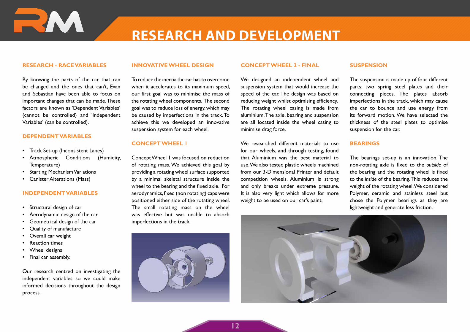
We designed an independent wheel and suspension system that would increase the speed of the car. The design was based on reducing weight whilst optimising efficiency. The rotating wheel casing is made from aluminium. The axle, bearing and suspension are all located inside the wheel casing to minimise drag force.
We researched different materials to use for our wheels, and through testing, found that Aluminium was the best material to use. We also tested plastic wheels machined from our 3-Dimensional Printer and default competition wheels. Aluminium is strong and only breaks under extreme pressure. It is also very light which allows for more weight to be used on our car’s paint.
susPeNsioN
The suspension is made up of four different parts: two spring steel plates and their connecting pieces. The plates absorb imperfections in the track, which may cause the car to bounce and use energy from its forward motion. We have selected the thickness of the steel plates to optimise suspension for the car.
beariNGs
The bearings set-up is an innovation. The non-rotating axle is fixed to the outside of the bearing and the rotating wheel is fixed to the inside of the bearing. This reduces the weight of the rotating wheel. We considered Polymer, ceramic and stainless steel but chose the Polymer bearings as they are lightweight and generate less friction.
ReseaRCh and deveLOPmenT
12
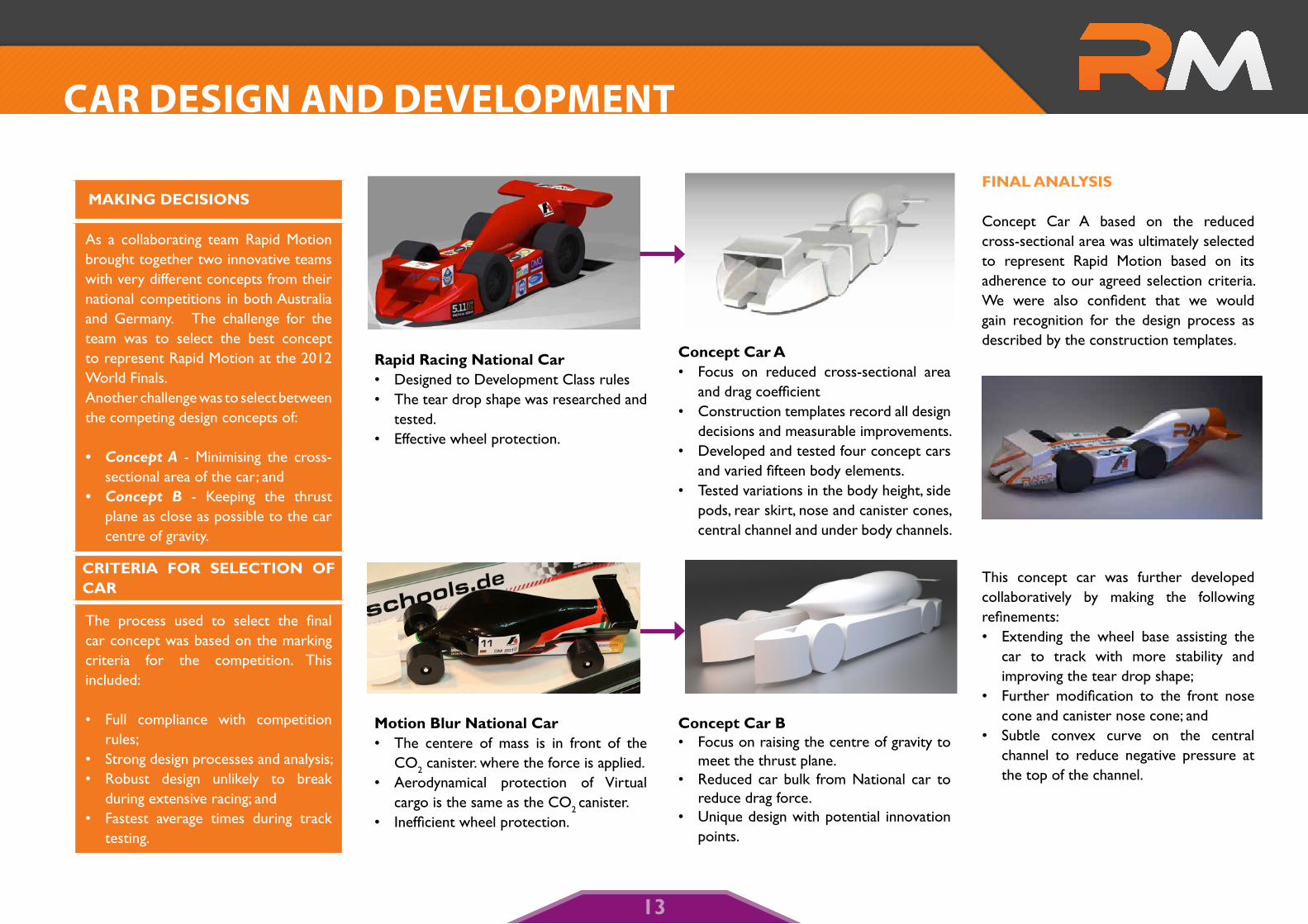
makiNG decisioNs
As a collaborating team Rapid Motion brought together two innovative teams with very different concepts from their national competitions in both Australia and Germany. The challenge for the team was to select the best concept to represent Rapid Motion at the 2012 World Finals. Another challenge was to select between the competing design concepts of:
• ConceptA - Minimising the cross-sectional area of the car; and
• Concept B - Keeping the thrust plane as close as possible to the car centre of gravity.
criTeria For selecTioN oF car
The process used to select the final car concept was based on the marking criteria for the competition. This included:
• Full compliance with competition rules;
• Strong design processes and analysis;• Robust design unlikely to break
during extensive racing; and • Fastest average times during track
testing.
rapid racing National car• Designed to Development Class rules• The tear drop shape was researched and
tested. • Effective wheel protection.
motion blur National car• The centere of mass is in front of the
CO2 canister. where the force is applied.• Aerodynamical protection of Virtual
cargo is the same as the CO2 canister.• Inefficient wheel protection.
concept car a• Focus on reduced cross-sectional area
and drag coefficient • Construction templates record all design
decisions and measurable improvements. • Developed and tested four concept cars
and varied fifteen body elements. • Tested variations in the body height, side
pods, rear skirt, nose and canister cones, central channel and under body channels.
concept car b• Focus on raising the centre of gravity to
meet the thrust plane. • Reduced car bulk from National car to
reduce drag force.• Unique design with potential innovation
points.
FiNal aNalysis
Concept Car A based on the reduced cross-sectional area was ultimately selected to represent Rapid Motion based on its adherence to our agreed selection criteria. We were also confident that we would gain recognition for the design process as described by the construction templates.
This concept car was further developed collaboratively by making the following refinements: • Extending the wheel base assisting the
car to track with more stability and improving the tear drop shape;
• Further modification to the front nose cone and canister nose cone; and
• Subtle convex curve on the central channel to reduce negative pressure at the top of the channel.
CaR desIgn and deveLOPmenT
13
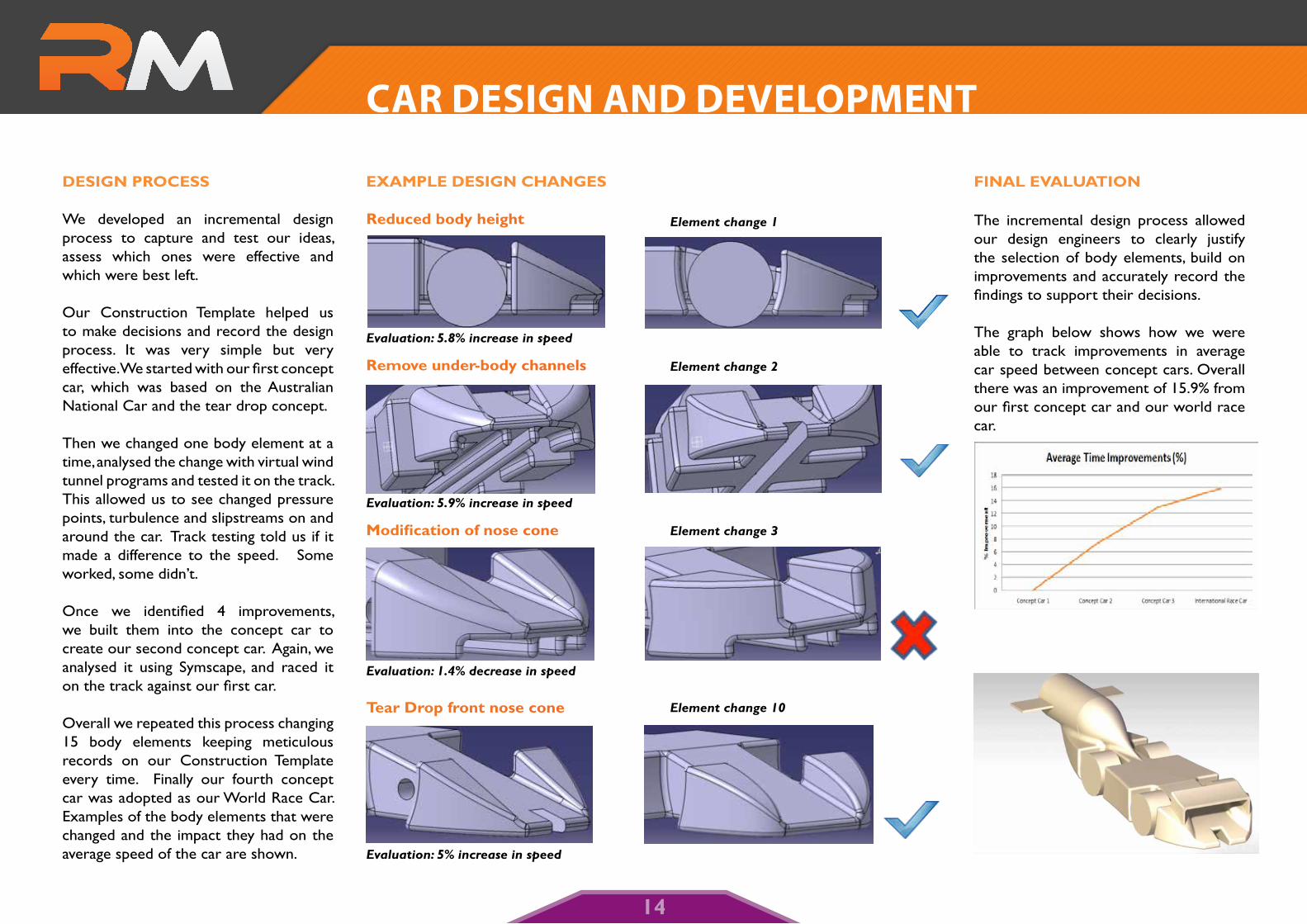
desiGN Process
We developed an incremental design process to capture and test our ideas, assess which ones were effective and which were best left.
Our Construction Template helped us to make decisions and record the design process. It was very simple but very effective.We started with our first concept car, which was based on the Australian National Car and the tear drop concept.
Then we changed one body element at a time, analysed the change with virtual wind tunnel programs and tested it on the track. This allowed us to see changed pressure points, turbulence and slipstreams on and around the car. Track testing told us if it made a difference to the speed. Some worked, some didn’t.
Once we identified 4 improvements, we built them into the concept car to create our second concept car. Again, we analysed it using Symscape, and raced it on the track against our first car.
Overall we repeated this process changing 15 body elements keeping meticulous records on our Construction Template every time. Finally our fourth concept car was adopted as our World Race Car. Examples of the body elements that were changed and the impact they had on the average speed of the car are shown.
examPle desiGN chaNGes
reduced body height
Evaluation:5.8%increaseinspeed
remove under-body channels
Evaluation:5.9%increaseinspeed
Modification of nose cone
Evaluation:1.4%decreaseinspeed
Tear drop front nose cone
Evaluation:5%increaseinspeed
Elementchange1
Elementchange2
Elementchange3
Elementchange10
FiNal evaluaTioN
The incremental design process allowed our design engineers to clearly justify the selection of body elements, build on improvements and accurately record the findings to support their decisions.
The graph below shows how we were able to track improvements in average car speed between concept cars. Overall there was an improvement of 15.9% from our first concept car and our world race car.
CaR desIgn and deveLOPmenT
14
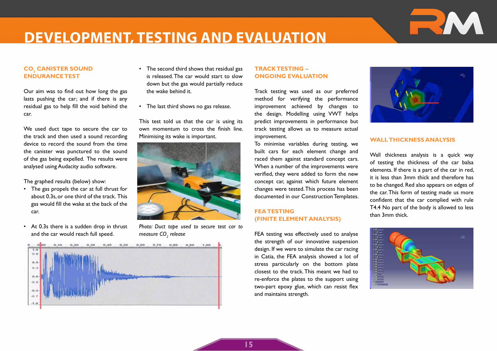
co2 caNisTer souNd eNduraNce TesT
Our aim was to find out how long the gas lasts pushing the car; and if there is any residual gas to help fill the void behind the car.
We used duct tape to secure the car to the track and then used a sound recording device to record the sound from the time the canister was punctured to the sound of the gas being expelled. The results were analysed using Audacity audio software.
The graphed results (below) show:• The gas propels the car at full thrust for
about 0.3s, or one third of the track. This gas would fill the wake at the back of the car.
• At 0.3s there is a sudden drop in thrust and the car would reach full speed.
• The second third shows that residual gas is released. The car would start to slow down but the gas would partially reduce the wake behind it.
• The last third shows no gas release. This test told us that the car is using its own momentum to cross the finish line. Minimising its wake is important.
Photo: Duct tape used to secure test car to measure CO2 release
Track TesTiNG – oNGoiNG evaluaTioN
Track testing was used as our preferred method for verifying the performance improvement achieved by changes to the design. Modelling using VWT helps predict improvements in performance but track testing allows us to measure actual improvement. To minimise variables during testing, we built cars for each element change and raced them against standard concept cars. When a number of the improvements were verified, they were added to form the new concept car, against which future element changes were tested. This process has been documented in our Construction Templates.
Fea TesTiNG (FiNiTe elemeNT aNalysis)
FEA testing was effectively used to analyse the strength of our innovative suspension design. If we were to simulate the car racing in Catia, the FEA analysis showed a lot of stress particularly on the bottom plate closest to the track. This meant we had to re-enforce the plates to the support using two-part epoxy glue, which can resist flex and maintains strength.
Wall ThickNess aNalysis
Wall thickness analysis is a quick way of testing the thickness of the car balsa elements. If there is a part of the car in red, it is less than 3mm thick and therefore has to be changed. Red also appears on edges of the car. This form of testing made us more confident that the car complied with rule T4.4 No part of the body is allowed to less than 3mm thick.
deveLOPmenT, TesTIng and evaLuaTIOn
15
TesTiNG The Tear droP coNcePT
The perfect teardrop shape has the lowest coefficient of friction of any shape (0.04). This means that for a constant cross sectional area, the tear drop would have the lowest drag force.
We analysed what makes the teardrop efficient and tried to adopt those features on our car. Our team modelled tear drop objects in the VWT and learned that:
• the curved nose produced limited pressure points where the object first hits the air, and there was almost no wake behind the pointy tail;
• the smooth curves on the side of the object created minimal turbulence and demonstrated by constant velocity lines almost parallel to each other; and
• reducing diameter of the object to its pointy tail trained the streamlines back behind the object so they did not separate away from its side.
We also changed the geometry of the tear drop (diameter to length ratio) to see how that impacted on pressure, velocity and the drag coefficient. We did not achieve a drag coefficient of 0.04 but we did learn how sensitive the drag coefficient is to minor changes to the geometry of the object.
virTual WiNd TuNNel
‘F1 in Schools’ Phonics is a program used by most F1 teams. It was great for a quick visual analysis of concept cars 1 and 2 and helped us understand the aerodynamic properties of the other 7 element changes. We analysed streamlines, pressure points and velocity to make changes so that the aerodynamics more closely resembled the teardrop tested. For example, VWT helped us to see that:
• removal of under body channels reduced turbulence;
• rounded (in the vertical plane) wheel protection reduced pressure points on the nose cone;
• wider central channel on the ‘bonnet’ improved streamlines and the velocity air around the car.
Each of the changes were also tested on the track and proven to improve the speed of the car.
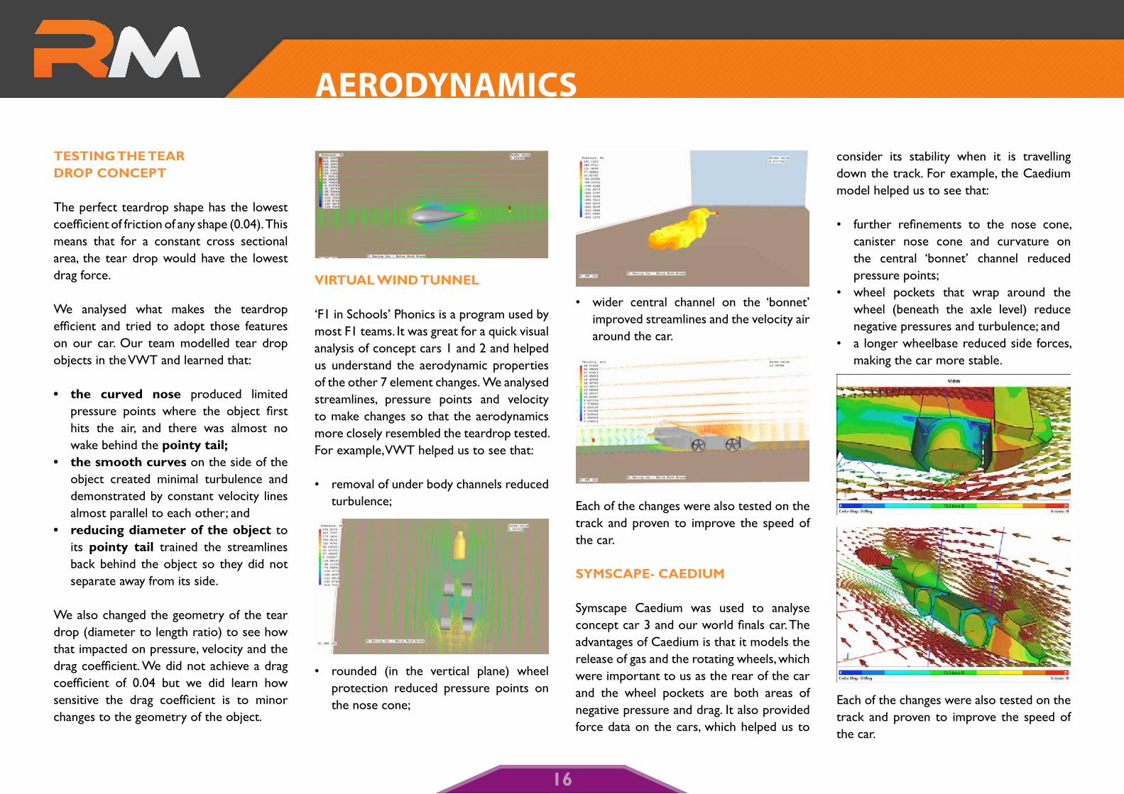
symscaPe- caedium
Symscape Caedium was used to analyse concept car 3 and our world finals car. The advantages of Caedium is that it models the release of gas and the rotating wheels, which were important to us as the rear of the car and the wheel pockets are both areas of negative pressure and drag. It also provided force data on the cars, which helped us to
consider its stability when it is travelling down the track. For example, the Caedium model helped us to see that:
• further refinements to the nose cone, canister nose cone and curvature on the central ‘bonnet’ channel reduced pressure points;
• wheel pockets that wrap around the wheel (beneath the axle level) reduce negative pressures and turbulence; and
• a longer wheelbase reduced side forces, making the car more stable.
Each of the changes were also tested on the track and proven to improve the speed of the car.
aeROdynamICs
16
machiNiNG Process
The cars were manufactured in two ways. In Germany, they were professionally manufactured by sponsors and in Australia, they were manufactured on the school Denford CNC router so that the team could demonstrate a high level of CNC machining competence and an understanding of the complex techniques and processes used to machine a car.
The following process outlines machining on the Denford CNC router with a 6mm ball nose cutter.
Machining codes – Quick Cam 3D Pro was used to convert our CAD drawings into machining codes. Like in a commercial engineering workshop, we considered two main factors: • Accuracy and quality of the finish; and • Time efficiency.
Staged machining processes were trialled to produce the best quality finish, in the fastest machining time. The stages are discussed below.
Roughingcut - A roughing cut with 1mm machining allowance and a 2mm step over, was used to remove the bulk of the balsa. This is fast machining which prepares the car for the accurate machining stages that follow.
Parallel pencil milling – Using a 0.1mm step over, parallel pencil milling was used to machine the detailed parts. We trialled different raster angle finish cuts but to achieve the same quality finish we found pencil milling to be a more direct and efficient process to get accuracy in areas such as the wheel pockets. This was a time efficient way of obtaining the detail on the car.
Finishingcut - Using a 0.2mm step over and a run on a 225 degree raster angle, the finish cut accurately machines the car. As it is removing less balsa than the roughing cut, there is also less flex on the cutter which provides a finish with reduced scalloping. This fine cut reduces the amount of sanding needed to get a high quality finish accurate to the CAD design.
Four sided machining – The majority of the car was machined from the two sides however to achieve the central channel and the easy removal of the machining support, we used ‘ top and bottom’ machining during the finishing cut.
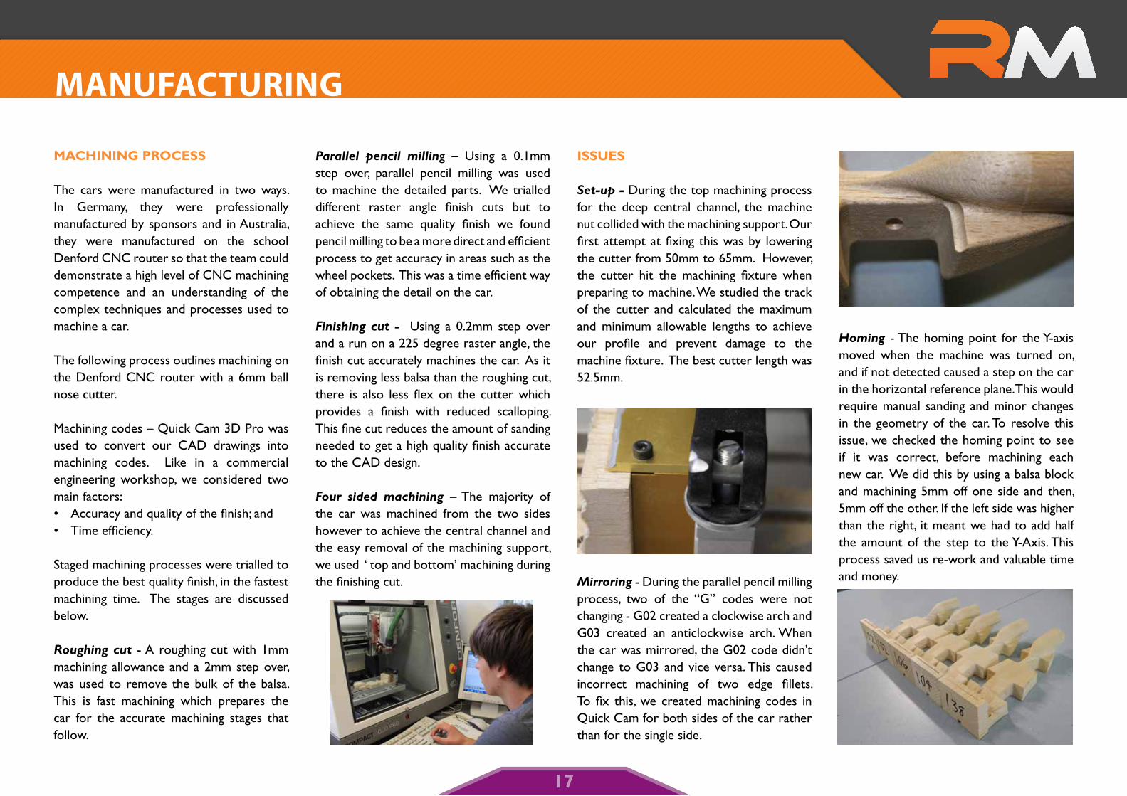
issues
Set-up- During the top machining process for the deep central channel, the machine nut collided with the machining support. Our first attempt at fixing this was by lowering the cutter from 50mm to 65mm. However, the cutter hit the machining fixture when preparing to machine. We studied the track of the cutter and calculated the maximum and minimum allowable lengths to achieve our profile and prevent damage to the machine fixture. The best cutter length was 52.5mm.
Mirroring - During the parallel pencil milling process, two of the “G” codes were not changing - G02 created a clockwise arch and G03 created an anticlockwise arch. When the car was mirrored, the G02 code didn’t change to G03 and vice versa. This caused incorrect machining of two edge fillets. To fix this, we created machining codes in Quick Cam for both sides of the car rather than for the single side.
Homing - The homing point for the Y-axis moved when the machine was turned on, and if not detected caused a step on the car in the horizontal reference plane. This would require manual sanding and minor changes in the geometry of the car. To resolve this issue, we checked the homing point to see if it was correct, before machining each new car. We did this by using a balsa block and machining 5mm off one side and then, 5mm off the other. If the left side was higher than the right, it meant we had to add half the amount of the step to the Y-Axis. This process saved us re-work and valuable time and money.
manuFaCTuRIng
17
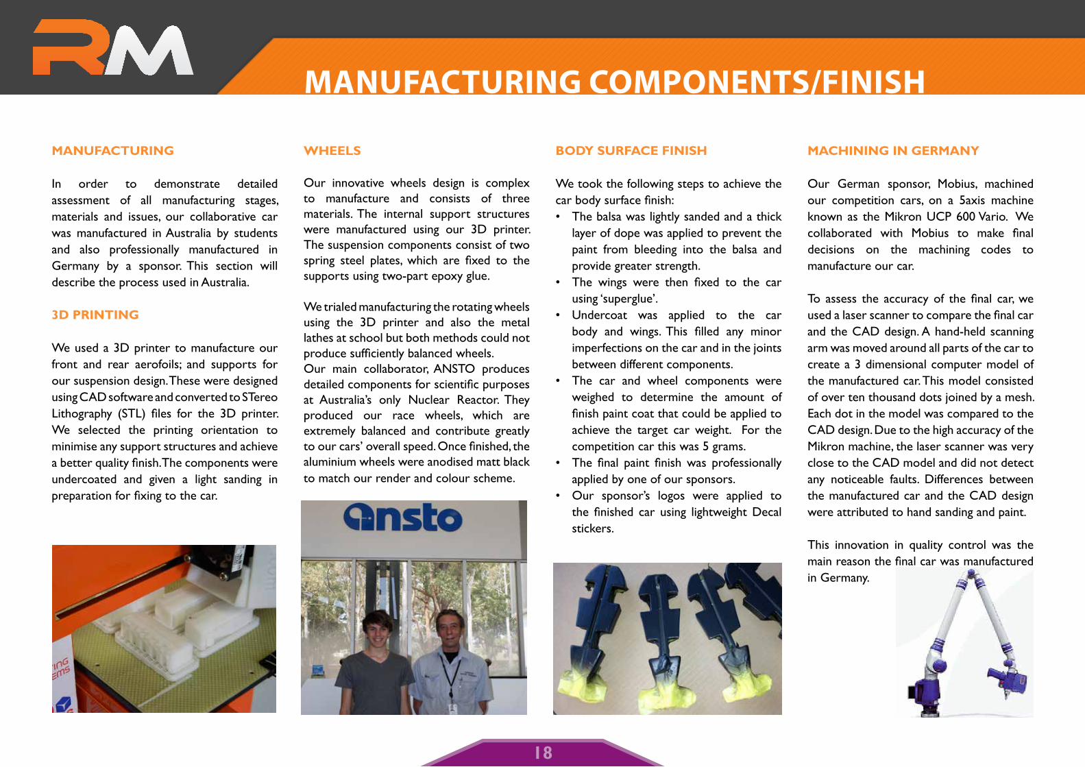
maNuFacTuriNG
In order to demonstrate detailed assessment of all manufacturing stages, materials and issues, our collaborative car was manufactured in Australia by students and also professionally manufactured in Germany by a sponsor. This section will describe the process used in Australia.
3d PriNTiNG
We used a 3D printer to manufacture our front and rear aerofoils; and supports for our suspension design. These were designed using CAD software and converted to STereo Lithography (STL) files for the 3D printer. We selected the printing orientation to minimise any support structures and achieve a better quality finish. The components were undercoated and given a light sanding in preparation for fixing to the car.
Wheels
Our innovative wheels design is complex to manufacture and consists of three materials. The internal support structures were manufactured using our 3D printer. The suspension components consist of two spring steel plates, which are fixed to the supports using two-part epoxy glue.
We trialed manufacturing the rotating wheels using the 3D printer and also the metal lathes at school but both methods could not produce sufficiently balanced wheels. Our main collaborator, ANSTO produces detailed components for scientific purposes at Australia’s only Nuclear Reactor. They produced our race wheels, which are extremely balanced and contribute greatly to our cars’ overall speed. Once finished, the aluminium wheels were anodised matt black to match our render and colour scheme.
body surFace FiNish
We took the following steps to achieve the car body surface finish:• The balsa was lightly sanded and a thick
layer of dope was applied to prevent the paint from bleeding into the balsa and provide greater strength.
• The wings were then fixed to the car using ‘superglue’.
• Undercoat was applied to the car body and wings. This filled any minor imperfections on the car and in the joints between different components.
• The car and wheel components were weighed to determine the amount of finish paint coat that could be applied to achieve the target car weight. For the competition car this was 5 grams.
• The final paint finish was professionally applied by one of our sponsors.
• Our sponsor’s logos were applied to the finished car using lightweight Decal stickers.
machiNiNG iN GermaNy
Our German sponsor, Mobius, machined our competition cars, on a 5axis machine known as the Mikron UCP 600 Vario. We collaborated with Mobius to make final decisions on the machining codes to manufacture our car.
To assess the accuracy of the final car, we used a laser scanner to compare the final car and the CAD design. A hand-held scanning arm was moved around all parts of the car to create a 3 dimensional computer model of the manufactured car. This model consisted of over ten thousand dots joined by a mesh. Each dot in the model was compared to the CAD design. Due to the high accuracy of the Mikron machine, the laser scanner was very close to the CAD model and did not detect any noticeable faults. Differences between the manufactured car and the CAD design were attributed to hand sanding and paint.
This innovation in quality control was the main reason the final car was manufactured in Germany.
manuFaCTuRIng COmPOnenTs/FInIsh
18
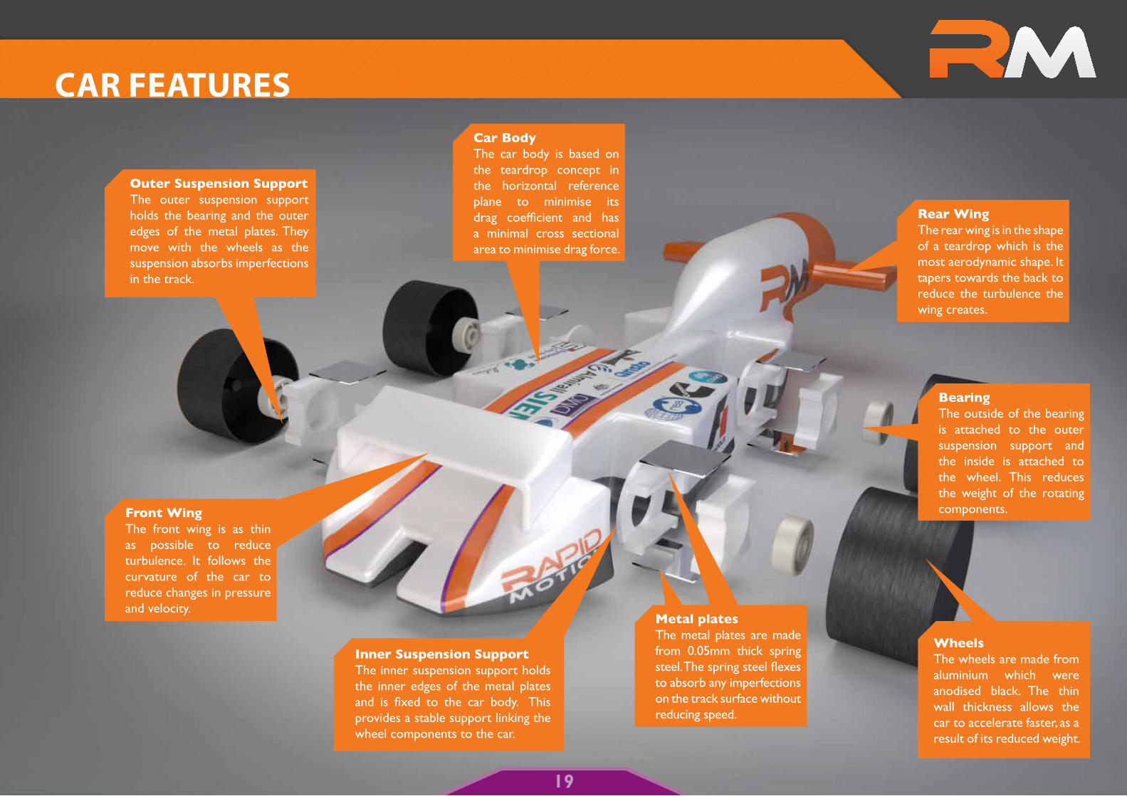
CaR FeaTuRes
Metal platesThe metal plates are made from 0.05mm thick spring steel. The spring steel flexes to absorb any imperfections on the track surface without reducing speed.
Inner Suspension SupportThe inner suspension support holds the inner edges of the metal plates and is fixed to the car body. This provides a stable support linking the wheel components to the car.
Front WingThe front wing is as thin as possible to reduce turbulence. It follows the curvature of the car to reduce changes in pressure and velocity.
Outer Suspension SupportThe outer suspension support holds the bearing and the outer edges of the metal plates. They move with the wheels as the suspension absorbs imperfections in the track.
WheelsThe wheels are made from aluminium which were anodised black. The thin wall thickness allows the car to accelerate faster, as a result of its reduced weight.
BearingThe outside of the bearing is attached to the outer suspension support and the inside is attached to the wheel. This reduces the weight of the rotating components.
Rear WingThe rear wing is in the shape of a teardrop which is the most aerodynamic shape. It tapers towards the back to reduce the turbulence the wing creates.
Car BodyThe car body is based on the teardrop concept in the horizontal reference plane to minimise its drag coefficient and has a minimal cross sectional area to minimise drag force.
19
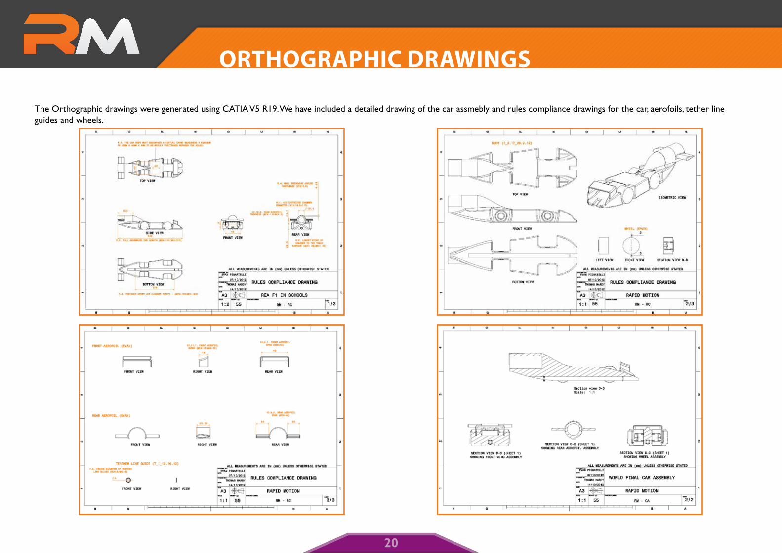
The Orthographic drawings were generated using CATIA V5 R19. We have included a detailed drawing of the car assmebly and rules compliance drawings for the car, aerofoils, tether line guides and wheels.
ORThOgRaPhIC dRaWIngs
20