auma ac 01.2 control
DESCRIPTION
AUMA actuator ac 01.2 modbus control documentTRANSCRIPT

Actuator controls
AUMATIC AC 01.2
Modbus RTU
To be used in combination with the operation instructions only!● The present short instructions do NOT replace the operation instructions!● They are only intended for persons already familiar with the operation instructions
where safety instructions, assembly, operation and commissioning are already describedin detail!
● The operation instructions must always be available.
FO connectionShort instructions
Table of contents Page
31. Short description...................................................................................................................
42. FO connection........................................................................................................................42.1. Basic information52.2. FO terminal compartment: open52.3. FO cables: connect72.4. FO terminal compartment: close
83. Network topologies................................................................................................................83.1. Line topology93.2. Star topology
103.3. Loop topology (two-fibre loop)
114. Corrective action....................................................................................................................114.1. LED indications
125. Technical data.........................................................................................................................125.1. FO connection board:
146. Appendix.................................................................................................................................146.1. Measuring methods146.2. Reference addresses146.3. Literature
2
Table of contents

1. Short description
AUMA actuator controls with FO connection are intended for use in optical fieldbusnetworks.
The FO connection integrated in the electrical connection enables the conversionfrom electrical RS-485 signals into optical signals and vice versa.
FO connection behaviour is passive at the bus, i.e. control of AUMA actuators is viabus is made in the same way as for a connection via copper cables (RS-485).
Contrary to RS-485 based systems, different topologies are possible:
● Line topology● Star topology● Redundant loop topologyApart from the large distances, FO cables offer further advantages:
● In environments with electromagnetic interference● Lightning arrester or overvoltage protection● Equipotential earth bonding and earthing● Galvanic separation of the actuator● Use of common cable trenches for power and signal cables● Prevention of interference emissions along the transmission lineThis allows for customised solutions for various applications such as water/wastewater industries, tunnelling, power plants, thermal industry or telecontrol engineering.
3
Short description

2. FO connection
2.1 Basic information
Hazardous voltage!
Risk of electric shock. Failure to observe this warning can result in death or seriousinjury.
→ The connection must be carried out exclusively by suitably qualified personnel.→ Prior to opening: Disconnect both system and device from the mains.→ Observe basic information contained in this chapter.→ Observe safety instructions contained in the operation instructions pertaining
to the actuator.
Eye damage caused by open fibre optic cable ends!
→ NEVER look directly into open cable ends or FO cable connections.
Connection or receive problems when ignoring the installation instructions!
→ Only using FO cable connection (connector types) with the wiring techniquesindicated in these instructions.
→ Only mount connector types with locking mechanisms in the defined position.→ Protect unused FO cable connections against contamination or dust with protec-
tive caps/plugs supplied by the factory.→ Connect incoming FO cable with the optical receiver, the outgoing FO cable
with the optical sender. NOT vice versa!→ Do NOT kink FO cables! Observe bending radius of cable manufacturer.
Cable and wire types
Table 1: Cables and wires according DIN VDE 0888 part 3:
Multi-mode 62.5 (50)/125 μmSingle-mode 9/125 μm
Fibre
62.5 (50)/125 μm glass fibre (multi-mode): 2,500 m9/125 μm glass fibre (single-mode): 15 km
Range
Recommendation: < 2.0 dB/km (multi-mode) or < 0.4 dB/km(single-mode)
Damping coefficient
Remove outer sheathing of FO cable at a length of approx. 42 cm to enable loopwiring in the terminal compartment.
Figure 1: Plug types: ST or SC (depending on version)
Controls mounted to wall bracket
In the event of heavy vibration of the valve, we recommend mounting the actuatorcontrols separately from the actuator on a wall bracket. For information about thewall bracket, refer to operation instructions for the actuator.
4
FO connection
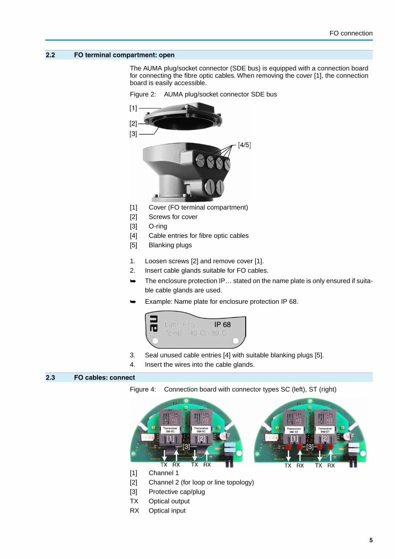
2.2 FO terminal compartment: open
The AUMA plug/socket connector (SDE bus) is equipped with a connection boardfor connecting the fibre optic cables. When removing the cover [1], the connectionboard is easily accessible.
Figure 2: AUMA plug/socket connector SDE bus
[1] Cover (FO terminal compartment)[2] Screws for cover[3] O-ring[4] Cable entries for fibre optic cables[5] Blanking plugs
1. Loosen screws [2] and remove cover [1].2. Insert cable glands suitable for FO cables.
➥ The enclosure protection IP… stated on the name plate is only ensured if suita-ble cable glands are used.
➥ Example: Name plate for enclosure protection IP 68.
3. Seal unused cable entries [4] with suitable blanking plugs [5].4. Insert the wires into the cable glands.
2.3 FO cables: connect
Figure 4: Connection board with connector types SC (left), ST (right)
[1] Channel 1[2] Channel 2 (for loop or line topology)[3] Protective cap/plugTX Optical outputRX Optical input
5
FO connection

A label on the connector indicates the wiring (fibre type, connector type).
Table 2: Markings on the label
FO cable connector typeFO cable fibre typeST = Straight tip (BNC connector)SM = Single-mode
SC = Subscriber connector (Snap-in connector)MM = Multi-mode
FO cables: connect
1. Install cables within the terminal compartment in a loop to achieve the highestpossible bending radius.
Figure 5: Wiring within in the terminal compartment
2. Measure and record the damping of the FO cables before connection.3. Link connectors crosswise:
Output TX of actuator 1 to input RX of actuator 2Input RX of actuator 1 to input TX of actuator 2Figure 6: Example of ST BNC connector
➥ Make sure that:
- the bayonet-type connection of connector type ST is properly engaged- the straight tip of connector type SC fully mates the FO cable socket.4. Protect unused FO cable connections against contamination or dust with pro-
tective caps/plugs supplied by the factory.
6
FO connection

2.4 FO terminal compartment: close
Figure 7: AUMA plug/socket connector SDE bus
[1] Cover[2] Screws for cover[3] O-ring[4] Cable entries for fibre optic cables[5] Blanking plugs
1. Clean sealing faces of cover [1] and housing.2. Apply a thin film of non-acidic grease (e.g. petroleum jelly) to the sealing faces.3. Check whether O-ring [3] is in good condition, correctly insert O-ring.4. Fit cover [1] and fasten screws [2] evenly crosswise.5. Fasten cable glands with the specified torque to ensure the required enclosure
protection.
7
FO connection

3. Network topologiesWhen connecting several terminal devices (actuators) in a network, the structure iscalled network topology. AUMA offers 3 different network topologies.
3.1 Line topology
Figure 8: Structure for line topology
Max. FO cable range in km (observe technical data!)[1] Channel 1[2] Channel 2[3] Any Modbus RTU device[4] FO coupler at DCS (mandatory)[5] FO coupler for any Modbus RTU field device
Special features of line topology
The optical signal is converted into an electrical signal at each device. Prior totransmission to the next device, the electrical signal is converted into an opticalsignal.
Interruption of an FO cable (case A) or failure of an FO connection board (case B)results in a loss of control for the subsequent actuators:
Case A(standard)
As soon as the electrical connection is removed from the , the FO connection of thisactuator is no longer available. As a consequence, communication with thesubsequent actuators is lost.To prevent this, the FO connection used in the can alsobe externally supplied with 24 V DC.
Case B(option)
As soon as the actuator is switched off (motor voltage), the FO connection board ofthis actuator is no longer available. As a consequence, communication with thesubsequent actuators is lost.To prevent this, the complete can be externally suppliedwith 24 V DC.
8
Network topologies

Information ● Communication of the following devices is monitored by channel 2. In the eventof loss of communication (i.e. no response from the next device), the showsthe following indication: Wrn FOC.
● If the actuator is the last device of the line topology, the monitoring functionshould be deactivated (parameter FO cable monitoring M0709 = Off (final devi-ce).
● Ensure proper termination for RS-485 connection of FO coupler.
3.2 Star topology
Figure 9: Structure for star topology
Max. FO cable range in km (observe technical data!)[1] Channel 1[2] Channel 2[3] Any Modbus RTU field device[4] FO coupler at DCS (mandatory)[5] FO coupler for any Modbus RTU field device
Special features of star topology
Failure of an FO cable section or of an actuator's FO connection board has no effecton the operability of the remaining actuators.
Information ● As all AUMA actuators are operated at the end of the FO cable section andcontrolled via channel 1, the parameter FO cable monitoring M0709 should beset to Off (final device).
● Ensure proper termination for RS-485 connection of FO coupler.
9
Network topologies

3.3 Loop topology (two-fibre loop)
Figure 10: Structure for loop topology
Max. FO cable range in km (observe technical data!)[1] Channel 1[2] Channel 2[3] Integration of any Modbus RTIU device (option)[4] FO coupler at DCS (mandatory)[5] FO coupler for any Modbus RTU field device
Special features of loop topology
● The interruption of an FO cable between two actuators is recognised by theredundancy modules (via parameter FO cablemonitoring = On (not final device)).Both display and the bus indicate Wrn FOC. The network is then operated asan optical line and all actuators remain available.
● If one module fails (i.e. when the voltage supply is interrupted), only the actuatorconnected to this module is disconnected from the loop, the remaining networkstays operative as a line. All other actuators remain available.
● The actuators have a redundant FO cable connection with a standard ModbusRTU interface (not redundant).
Cable routing and PLC fault evaluation
● To increase service safety, install cables for go-and-return in the loop on sepa-rate lines.
● To achieve complete monitoring of the redundant optical loop, all FO fault signals(including the fault output of the FO coupler) at the master must be evaluatedby the PLC controls.
10
Network topologies
4. Corrective action
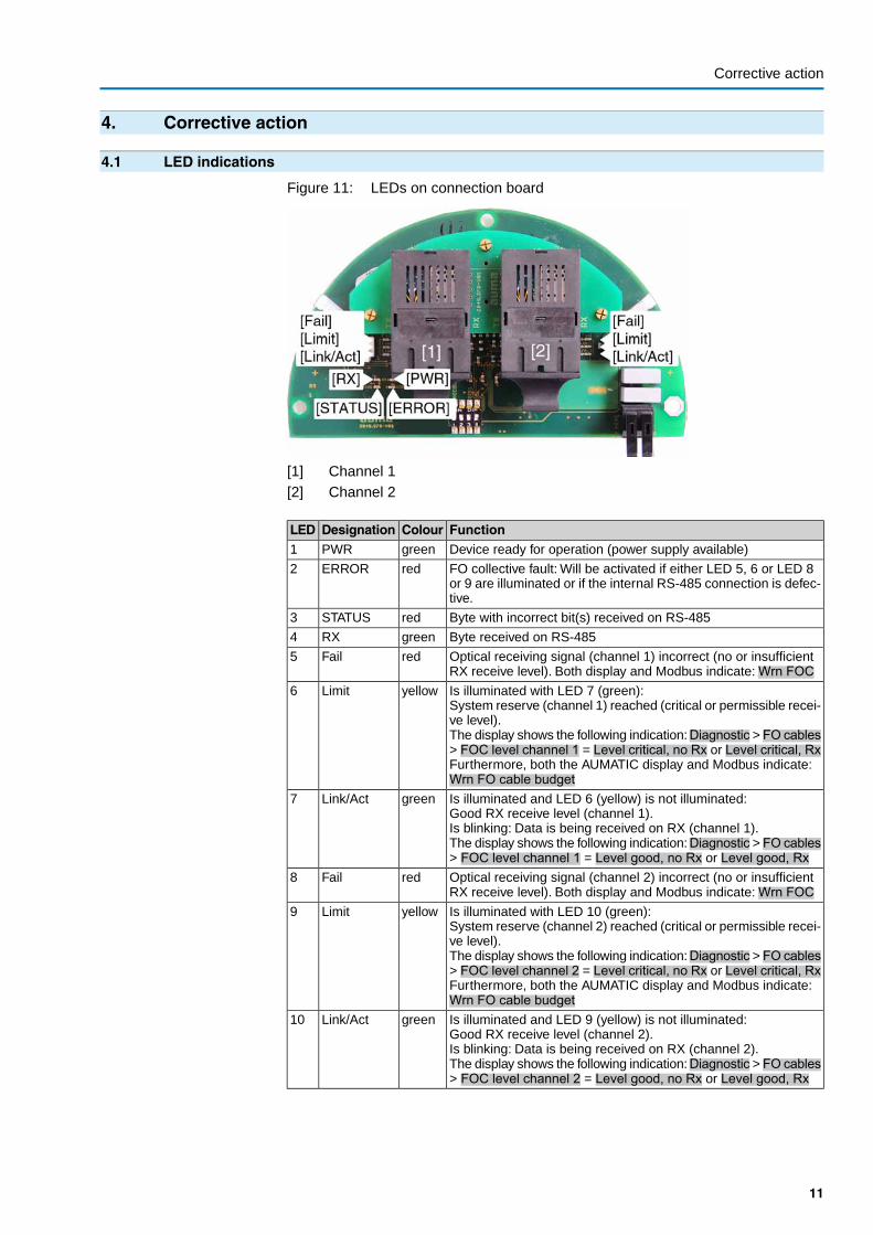
4.1 LED indications
Figure 11: LEDs on connection board
[1] Channel 1[2] Channel 2
FunctionColourDesignationLEDDevice ready for operation (power supply available)greenPWR1
FO collective fault: Will be activated if either LED 5, 6 or LED 8or 9 are illuminated or if the internal RS-485 connection is defec-tive.
redERROR2
Byte with incorrect bit(s) received on RS-485redSTATUS3
Byte received on RS-485greenRX4
Optical receiving signal (channel 1) incorrect (no or insufficientRX receive level). Both display and Modbus indicate: Wrn FOC
redFail5
Is illuminated with LED 7 (green):System reserve (channel 1) reached (critical or permissible recei-ve level).The display shows the following indication:Diagnostic > FO cables> FOC level channel 1 = Level critical, no Rx or Level critical, RxFurthermore, both the AUMATIC display and Modbus indicate:Wrn FO cable budget
yellowLimit6
Is illuminated and LED 6 (yellow) is not illuminated:Good RX receive level (channel 1).Is blinking: Data is being received on RX (channel 1).The display shows the following indication:Diagnostic > FO cables> FOC level channel 1 = Level good, no Rx or Level good, Rx
greenLink/Act7
Optical receiving signal (channel 2) incorrect (no or insufficientRX receive level). Both display and Modbus indicate: Wrn FOC
redFail8
Is illuminated with LED 10 (green):System reserve (channel 2) reached (critical or permissible recei-ve level).The display shows the following indication:Diagnostic > FO cables> FOC level channel 2 = Level critical, no Rx or Level critical, RxFurthermore, both the AUMATIC display and Modbus indicate:Wrn FO cable budget
yellowLimit9
Is illuminated and LED 9 (yellow) is not illuminated:Good RX receive level (channel 2).Is blinking: Data is being received on RX (channel 2).The display shows the following indication:Diagnostic > FO cables> FOC level channel 2 = Level good, no Rx or Level good, Rx
greenLink/Act10
11
Corrective action

5. Technical data
Information The following technical data includes standard and optional features. For detailedinformation on the customer-specific version, refer to the order-relevant data sheet.This data sheet can be downloaded from the Internet at http://www.auma.com inGerman and English (indication of commission number required).
5.1 FO connection board:
ST (BNC connector) or SC (Snap-in connector)FO connection
For line topology: 2 x IN/OUTFor star topology: 1 x IN/OUTFor loop topology: 2 x IN/OUT
Channels (optical)
Maximum 115,2 KBit/sAutomatic recognition of the following baud rates:9,6KBit/s, 19,2KBit/s, 38,4KBit/s, 57,6KBit/s, 115,2KBit/s
Data rate:
Half-duplexTransmission type
RS-485 ↔ Fiber optic cable: < 3 TBitTx ↔ Rx: 11 TBit
Propagation delay
Multi-mode 62.5 (50)/125 μmSingle-mode 9/125 μm
Fibre
For multi-mode fibre: 13 dBFor single-mode fibre: 17 dB
Optical budget
62.5/125 μm glass fibre (multi-mode):2,500 m (FO cable damping max. 2.0 dB/km, without additional damping)
Network range max.
50/125 μm glass fibre (multi-mode):2,500 m (FO cable damping max. 2.0 dB/km, without additional damping)
9/125 μm glass fibre (single-mode):15 km (FO cable damping max. 0.4 dB/km, without additional damping)
1,310 nmWave length
–25 °C to +50 °COperation temperature
24 V DC/70 mA, internally supplied via power supply unit of the AUMATIC. External voltagesupply of the AUMATIC 24 V DC/500 mA possible. Only once the AUMATIC is operated onexternal voltage supply will the bus remain uninterrupted in case of a loss of supply voltage.
Power supply
12
Technical data
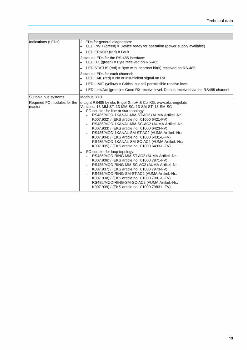
2 LEDs for general diagnostics:● LED PWR (green) = Device ready for operation (power supply available)
● LED ERROR (red) = Fault
2 status LEDs for the RS-485 interface:● LED RX (green) = Byte received on RS-485
● LED STATUS (red) = Byte with incorrect bit(s) received on RS-485
3 status LEDs for each channel:● LED FAIL (red) = No or insufficient signal on RX
● LED LIMIT (yellow) = Critical but still permissible receive level
● LED Link/Act (green) = Good RX receive level. Data is received via the RS485 channel
Indications (LEDs)
Modbus RTUSuitable bus systems
d-Light RS485 by eks Engel GmbH & Co. KG, www.eks-engel.deVersions: 13-MM-ST, 13-MM-SC, 13-SM-ST, 13-SM-SC● FO coupler for line or star topology:
- RS485/MOD-1KANAL-MM-ST-AC2 (AUMA Artikel.-Nr.:K007.932) / (EKS article no.: 01000 6421-FV)
- RS485/MOD-1KANAL-MM-SC-AC2 (AUMA Artikel.-Nr.:K007.933) / (EKS article no.: 01000 6423-FV)
- RS485/MOD-1KANAL-SM-ST-AC2 (AUMA Artikel.-Nr.:K007.934) / (EKS article no.: 01000 6431-L-FV)
- RS485/MOD-1KANAL-SM-SC-AC2 (AUMA Artikel.-Nr.:K007.935) / (EKS article no.: 01000 6433-L-FV)
● FO coupler for loop topology:- RS485/MOD-RING-MM-ST-AC2 (AUMA Artikel.-Nr.:
K007.936) / (EKS article no.: 01000 7971-FV)- RS485/MOD-RING-MM-SC-AC2 (AUMA Artikel.-Nr.:
K007.937) / (EKS article no.: 01000 7973-FV)- RS485/MOD-RING-SM-ST-AC2 (AUMA Artikel.-Nr.:
K007.938) / (EKS article no.: 01000 7981-L-FV)- RS485/MOD-RING-SM-SC-AC2 (AUMA Artikel.-Nr.:
K007.939) / (EKS article no.: 01000 7983-L-FV)
Required FO modules for themaster
13
Technical data

6. Appendix
6.1 Measuring methods
Figure 12: Damping measurement
6.2 Reference addresses
● Required FO module for the master:eks Engel GmbH & Co. KGSchützenstr. 2, 57482 Wenden-Hillmicke,Tel.: + 49-2762 - 9313 - 60,www.eks-engel.de
6.3 Literature
● Christoph P. WrobelOptische Übertragungstechnik in der PraxisGrundlagen, Komponenten, Installation, AnwendungenHüthig VerlagISBN 3-7785-2638-3
14
Appendix

15
Appendix

AUMA Riester GmbH & Co. KGP.O.Box 1362D 79373 MuellheimTel +49 7631 809 - 0Fax +49 7631 809 - [email protected]
Y005.495/003/en/4.12
For detailed information on AUMA products refer to the Internet: www.auma.com