august 2012 weld analysis - epsilon fea, llc · august 2012 weld analysis. 3 ... peak stress...
TRANSCRIPT

… within Epsilon
… within Epsilon
Twin Cities
ANSYS®
User Meeting
August 2012
Weld Analysis


3
… within Epsilon
ANSYS User Meeting
Agenda
1. Explicitly Modeled Welds
2. Extracting Stresses for Hand-Calculations– Path Operations
– Stress Linearization
3. Designing / Lifing Welds - -Chris Wright P.E.

4
… within Epsilon
ANSYS User Meeting
Explicitly Modeled Welds
1. Material Properties are undefined– Heat affected zone
• Composition varies spatially due to material mixing/cooling rates
• Would need fatigue properties gathered at various R-ratios and compositions?
• Welding/Cooling rates depend on weld process/operator
2. Geometric Variations also hard to assess
3. Process would be similar to Soldering/Semiconductor1. Model weld bead explicitly
2. Use viscoplastic material model (e.g. Anands)
3. Have modulus approach zero above weld temperature
4. Use Element Birth/Death to “activate” along the weld line
5. Use Heat Generation along weld as elements are activated
6. Cool with HTC’s for quiescent air… 5 btu/ft^2/sec-F?
4. Bound problem to assess (large) variation!
5
… within Epsilon
ANSYS User Meeting
Extracting Stress Data
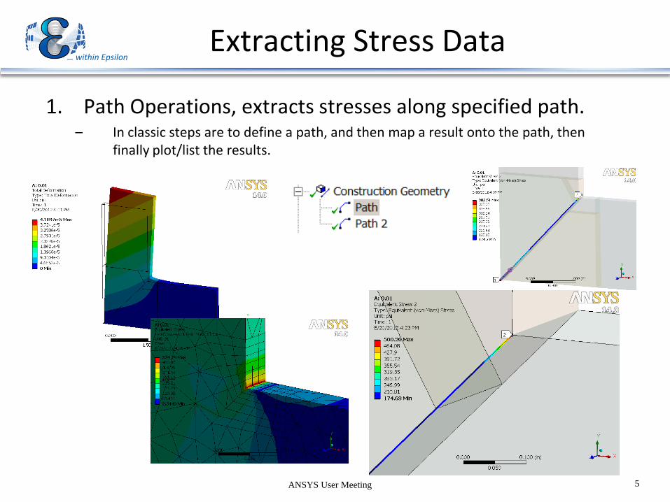
1. Path Operations, extracts stresses along specified path.– In classic steps are to define a path, and then map a result onto the path, then
finally plot/list the results.

6
… within Epsilon
ANSYS User Meeting
Extracting Stress Data
1. Path Operations, extracts stresses along specified path.– In classic steps are to define a path, and then map a result onto the path, then
finally plot/list the results.
– Highly Dependent on Mesh, and selection of points!
Coarse:500
Fine: 840

7
… within Epsilon
ANSYS User Meeting
Extracting Stress Data
1. Path Operations, Stress Linearization– Relatively sensitive to Mesh, and selection of points!
– Will match hand-calc's with no KT’s applied (in theory)
– Devolves stress into tensile and bending components!

8
… within Epsilon
ANSYS User Meeting
Extracting Stress Data
1. Path Operations, Stress Linearization
Fine: 187
Coarse: 188
Fine / Path 2: 187

Twin Cities ANSYS User Group
August 22, 2012
ANSYS and Weld Design

DESIGN FUNCTIONS
Connection (not weld) design
Load transfer
Load path definition
Determine loading
Magnitude
Distribution
Fabrication decisions
Weld type
Geometry constraints
Process variables
Quality assurance
Criteria
Working stress
Fatigue Assessment
CONSTRAINTS
Design code
Prescriptive requirements
Allowable stress
Methodology
Fabrication
Material weldability
Set up and tooling
Thermal effects
Labor intensive
Process qualifications
Welder skills
Quality Assurance
Customer requirements
Code requirements
Design Problem

Modeling ProblemPARAMETERS
Weld size
Type
Extent
BEHAVIOR
Static strength
Fatigue
response
Thermal
response
CONVENTIONAL DESIGN
Weld load carried by shear across
throat
Direct loads distributed uniformly
Moment reactions vary radially
CRITERIA
0.3Fu (AISC)
0.6S for groove weld shear (ASME)
0.49S for fillet weld shear (ASME)
Separate fatigue assessment
IMPLICIT WELD MODEL
Weld joint defined by coupling or constraints
Weld loading developed by equilibrium and
continuity
Nodal forces define connection load
distribution
Apply design code requirements
EXPLICIT WELD MODEL
Weld contour defined in nodal mesh
Peak stress calculated by path operation
TRADE-OFFS
Implicit Explicit
Weld size
determined by from
results
Weld design
required
beforehand
Real world
features implied
by Code
Weld contours
and metallurgy
idealized
Mesh refinement
not required
Refined mesh
required
No remesh required
to vary weld size
or type
Weld redesign
requires re-
model

Spot weld
Fillet weld with
porosity
Stiffener weld
Flare bevel
Fillet weld
Weld Fabrication

Quality Issues
Porosity and root opening
UndercutStart and stop craters
Procedural errors

Clevis Weld Load
0
1000
2000
3000
4000
0 1 2 3 4 5 6 7 8
Distance along weld—in
Un
it L
oad
—lb
/in
tail run nose
average load
Chain LinkClevis Plate Stress
0 5 1 0 1 5 2 0 2 5 3 0 4 03 5
St r e s s (k s i)
n o s e
t a il
r u n

AISC/AWS Weld Design
Elastic MethodUltimate Strength Method

Weld Unit Load
0
2000
4000
6000
8000
10000
12000
14000
16000
18000
0 2 4 6 8 10 12 14 16 18 20
Distance along weld — in
Unit L
oad
(Q
) -
lb/in
FEA
Elastic Analysis
0
5
1 0
1 5
2 0
2 5
3 0
3 5
4 0
5
10
10
3 1 . 6 k
Eq u iv a l e n t S t re s s
(k s i )
1/ 4
•3/8 Bracket plate fillet welded to
rectangular base plate fixed at edges
•Weld attachment simulated with rigid
constraints
•Weld force distribution compared to
AISC Elastic method
Bracket Plate

Prescriptive provisions
Specific weld joint details
Flange attachment
Opening details
Weld details
Types
Sizes
Allowable stresses
Construction dependent
Quality assurance
Joint efficiencies
��
Non Prescriptive Provisions
Attachments
Supports
Machinery
External loading
Piping loads
Impact
Unique construction
Non-circular openings
Proprietary items
Design by analysis (VIII-2)
Lower design margin
More restrictive quality assurance
Explicit weld analysis rules
ASME Code Design

Explicit Modeling
Shell Model
Solid Model

0
2 5 0 0
5 0 0 0
2 0 0 0 0
7 5 0 0
1 0 0 0 0
1 2 5 0 0
1 5 0 0 0
1 7 5 0 0
X
Y
6 . 7 5 x 1 . 5 f ac e b a r
2 9 . 5 O D x 1 . 7 5 t k p la t e
Face Bar Weld Load
0
1000
2000
3000
4000
5000
0 2 4 6 8 10 12 14
Distance along weld—in
Wel
d L
oad
—lb
/in
Non-Circular Opening•Pressurized bulkhead 29.5 in OD x 1.75 in thick
with reinforced 16.25 x 12.75 rectangular opening
•Face bar attachment simulated with rigid
constraints
•Weld force distribution checked against ASME
Code opening requirements

Fatigue AWS/AISC

Fatigue ASME Code
Table 5.11 Ğ Weld Surface Fatigue-Strength-Reduction Factors
Weld Surface Quality Levels (se e Table 5.12)
Condition Condition 1 2 3 4 5 6 7
Machined 1.0 1.5 1.5 2.0 2.5 3.0 4.0 Full penetration
As-welded 1.2 1.6 1.7 2.0 2.5 3.0 4.0
Final Surface Machined
NA 1.5 1.5 2.0 2.5 3.0 4.0
Final Surface
As-welded NA 1.6 1.7 2.0 2.5 3.0 4.0
Partial Penetration
Root NA 1.5 NA NA NA 3.0 4.0
Toe machined NA NA 1.5 NA 2.5 3.0 4.0
Toe as-welded NA NA 1.7 NA 2.5 3.0 4.0 Fillet
Root NA NA NA NA NA 3.0 4.0
Table 5.12 Ğ Weld Surface Fatigue-Strength-Reduction Factors
Fatigue-Strength-Reduction Factor
Quality Level
Definition
1.0 1 Machined or ground weld that receives a f ull volumetric examination,
and a surface that receives MT/PT examination and a VT examination.
1.2 1 As-welded weld that receives a f ull volumetric examination, and a surface that receives MT/PT and VT examination
1.5 2
Machined or ground weld that receives a partial volumetric examination, and a surface that receives MT/PT examination and VT examination
1.6 2 As-welded weld that receives a partial volumetric examination, and a surface that receives MT/PT and VT examination
1.5 3
Machined or ground weld surface that receives MT/PT examination and a VT examination (visual), but the weld receives no volumetric examination inspection
1.7 3
As-welded or ground weld surface that receives MT/PT examination and a VT examination (visual), but the weld receives no volumetric examination inspection
2.0 4 Weld has received a partial or f ull volumetric examination, and the surface has received VT examination, but no MT/PT examination
2.5 5 VT examination only of the surface; no volumetric examination nor MT/PT examination.
3.0 6 Volumetric examination only
4.0 7 Weld backsides that are non-definable and/or receive no examination.
Notes:
1. Volumetric examination is RT or UT in accordance with Part 7.
2. MT/PT examination is magnetic particle or liquid penetrant examination in accordance with Part 7
3. VT examination is visual examination in accordance with Part 7.
ASME Code Fatigue rules originate from the Coffin-Manson
rule: the product of the plastic strain amplitude (half the
strain range under reversed loading) produced by a cyclic
loading and the number of cycles to crack initiation equals
half the fracture ductility:
p N = f2 =
1
2 Ln
100
100 - RA
where:
p amplitude of plastic strain
N number of cycles to crack initiation
RA Reduction of area from tensile test
f fracture ductility
Taking the total strain amplitude as the sum of the plastic
and elastic strain amplitudes and converting to stress by
multiplying by the elastic modulus the cyclic stress
amplitude to failure becomes
S = E
4 N Ln
100
100 - RA + ∆s
For materials showing an endurance limit ∆s is taken as the
endurance limit
S = E
4 N Ln
100
100 - RA + Se
B. F. Langer, ‘Design of Pressure Vessels for Low Cycle
Fatigue,’ J. of Basic Engineering, ASME Transactions,
September 1962.