august 19, 2016 - cityoflaredo.com of laredo - south laredo wastewater treatment plant ... listed on...
TRANSCRIPT

2517-96098 City of Laredo - South Laredo Wastewater Treatment Plant 12 MGD to 18 MGD Expansion Project ADDENDUM NO. 4
© 2016 CDM Smith ADD-1 ADDENDUM NO. 4
All Rights Reserved
August 19, 2016
ADDENDUM NO. 4
Date of Addendum: August 19, 2016
PROJECT NAME: South Laredo Wastewater Treatment Plant 12 MGD to 18 MGD Expansion
Project
Bidders on this project are hereby notified that this Addendum shall be attached to and made a part of the above named Contract Documents and Technical Specifications, dated July 2016. The following items are issued to add to, modify, and clarify the Contract Documents and Technical Specifications and Drawings. These items shall have full force and effect as the Contract Documents and Technical Specifications, and cost involved shall be included in bid prices. Bids to be submitted on the specific bid date shall conform with the additions and revisions listed herein. Acknowledge receipt of this addendum by designating receipt of the addendum on the Bid Form. Failure to do so may subject bidder to disqualification.
CHANGES TO PROJECT MANUAL
DIVISION A 1. Invitation to Bidder. Replace Section in its entirety. 2. Notice to Bidders. Replace Section in its entirety. 3. Information to Bidders. Replace Section in its entirety. 4. Proposal and Affidavit. Replace Section in its entirety. 5. Construction Contract. Remove page CC-1 and replace with the attached revised page CC-1. DIVISION B 1. Contract Time and Liquidated Damages. Replace Section in its entirety. SPECIFICATION SECTIONS
1. Section 03300 – Cast-In-Place Concrete. Remove Section 03300 in its entirety and replace with the
attached Section 03300. 2. Section 11370 – Positive Displacement Blowers. Remove Section 11370 in its entirety and replace
with the revised attached Section 11370. 3. Section 13306 – Instrumentation and Controls-Application Engineering Services. Remove page
13306-9 and replace with the attached page 13306-9. 4. Section 13340 – Instrumentation and Controls-Field Instruments. Remove Pages 13340-A-2 through
13340-A-5 and replace with the attached pages 13340-A-2 through 13340-A-5.

2517-96098 City of Laredo - South Laredo Wastewater Treatment Plant 12 MGD to 18 MGD Expansion Project ADDENDUM NO. 4
© 2016 CDM Smith ADD-2 ADDENDUM NO. 4
All Rights Reserved
CHANGES TO DRAWINGS
1. Drawing CP-12. Remove Drawing CP-12 and replace with attached Drawing CP-12. 2. Drawing CP-13. Remove Drawing CP-13 and replace with attached Drawing CP-13. 3. Drawing CP-16. Remove Drawing CP-16 and replace with attached Drawing CP-16. 4. Drawing SZ-9. Remove Drawing SZ-9 and replace with attached Drawing SZ-9.
CLARIFICATIONS
1. Question: Drawing P-10 shows a 3" Rotometer tag (FE-6060-02), however this instrument is not
listed on the instrument list in spec section 13340 or is indicated to be supplied by another Division. Please advise who is to provide this instrument and supply Rotometer spec's for pricing. Answer: Please refer to Sheet MG-2 Detail A and Specification 15120 for rotameter requirements.
2. Question: Drawing P-11 shows (3) 1/2" Rotometers tags (FE-2020-02, FE-2020-04, FE-2020-06,), however these instruments are not listed on the instrument list in spec section 13340 or is indicated to be supplied by another Division. Please advise who is to provide this instrument and supply spec's for pricing. Answer: Refer to Sheet MF-2 Detail B and Specification 15120 for rotameter requirements.
3. Question: Drawing P-11 show a Vane Actuated Flow Switch tag (FSl-2020-02). However, this
instrument is not listed on the instrument list in spec section 13340 or is indicated to be supply by another Division. Please advise who is to provide this instrument? Drawing P-11 show (3) Pressure Gauges tags (PI-2020-02, PI-2020-04, PI-2020-06) however these instruments are not on the instrument list in spec section 13340 or is indicated to be supplied another Division. Please advise who is to provide these instruments. Answer: Refer to updated Specification 13340.
4. Question: Drawing P-11 show (3) Pressure Gauges tags (PI-2020-02, PI-2020-04, PI-2020-06)
however these instruments are not on the instrument list in spec section 13340 or is indicated to be supplied another Division. Please advise who is to provide these instruments. Answer: Refer to updated Specification 13340.
5. Question: Drawing P-12 shows (3) 1/2" Rotometers tags (FE-2020-01, FE-2020-03, FE-2020-05) however these instruments are not listed on the instrument list in spec section 13340 or is not indicated to be supplied by another Division. Please advise who is to provide these instruments and supply spec's for pricing. Answer: Refer to Sheet MF-2 Detail B and Specification 15120 for rotameter requirements.
6. Question: Drawing P-12 show (3) Vane Actuated Flow Switches tags (FSL -2020-01, FSL -2020-
03), however these instrument are not listed on the instrument list in spec section 13340 or is not indicated to be supply by another Division. Please advise who is to provide this instrument? Answer: Refer to updated Specification 13340.
7. Question: Drawing P-12 show (3) Pressure Gauges tags (PI-2020-01, PI-2020-03, PI-2020-05)
however these instruments are not on the instrument list in spec section 13340 or is indicated to be supplied another Division. Please advise who is to provide these instruments.

2517-96098 City of Laredo - South Laredo Wastewater Treatment Plant 12 MGD to 18 MGD Expansion Project ADDENDUM NO. 4
© 2016 CDM Smith ADD-3 ADDENDUM NO. 4
All Rights Reserved
Answer: Refer to updated Specification 13340. 8. Question: There are several bid items in Division 13 that are not in a certain area at the plant for the
bid. Please advise where to place the following bids items from Division 13 specs: • Engineering Operator Workstation with Dual Monitors (OWS-3) • Spare/Test PLC • Training • Software GlobalCare • 120 Extra Programming Hours • Etc.
Answer: Include these work items to Bid Item No. 12. Refer to updated bid form in Document A6, Proposal and Affidavit.
9. Question: Is the PCSS required to provide references of similar sized projects, per Proposal and
Affidavit (Ref. Dwg. PA-5) Subcontractors? In Spec Section 13300-20 the PCSS’s are already pre-approved. Answer: Pre-approved PCSS is not required to provide references.
10. Question: We would like to be sure that we do NOT have to furnish a control panel or motor starter for the Odorous blower? It does state we will be reusing the existing local panel in Sec 11370 Part 1, 1.01 B.2. but we wanted to be sure that the Control Panel section only relates to the Chlorine Blowers. Secondly, in Section 2.05 B. it requests that we furnish the motor starter for the packages. Please clarify if we are reusing the existing Odorous blower's reduced voltage motor starter… or is there a VFD being installed under an electrical contractors scope of supply? Answer: The new standby odorous air blower unit will reuse existing local control panel and existing motor starter that were installed under the previous plant 6-MGD Expansion project. The control panel requirements in the specification relate to the chlorine contact basin blower.
11. Question: A Certified Factory Noise testing performed on a particular blower package would require
shipping to “sound lab” for certified testing at a very large cost, even if possible. Will submission of the sound maps the factory published for the blower packages be acceptable? Answer: A certified factory noise testing is required.
12. Question: In section 1.04 C. 4, PTC-9 Certified Performance Test. Gardner Denver may be the only
manufacturer still able to provide an ASME Factory Certified PTC-9 test. The cost to provide this test is almost the same cost of the blower. In lieu of the PTC-9 test, will the submission of performance curves, blower slip test and mechanical hot run test will be sufficient? Answer: Refer to updated specification 11370.
13. Question: Please consider a bid date extension. We have had several bids in the past few weeks and
my other lead estimator who is going to assist me on this project is on vacation until the end of this week. Answer: Refer to updated Division A documents including Invitation to Bidders, Notice to Bidders, and Information to Bidders.
14. Question: Please consider a time extension for more questions.
Answer: Refer to updated Division A documents including Invitation to Bidders, Notice to Bidders, and Information to Bidders.

2517-96098 City of Laredo - South Laredo Wastewater Treatment Plant 12 MGD to 18 MGD Expansion Project ADDENDUM NO. 4
© 2016 CDM Smith ADD-4 ADDENDUM NO. 4
All Rights Reserved
15. Question: After a brief review, I did not notice anything titled for the Owner’s “General Conditions”
or any “Supplementary Conditions.” I assume that all of the Owners standard conditions are included in other sections and just not titled this way? I do see references in the spec. book for “General Conditions” though. Answer: Division A, Division B, Division C, and Division D documents constitute the Owner’s Genera Conditions and Supplementary Conditions for this project.
16. Question: The bidders check list, CB-1, requires the bid form to be submitted in duplicate. Please consider allowing only 1 copy. We will not have time to make a photocopy of the bid form prior to turning in the bid. Due to the nature of these bids, we often cannot fill out many numbers until a few minutes before the bid is due. This bid form is long and submitting in duplicate will only create room for possible errors as we will have to handwrite each form. Answer: As directed by the City of Laredo, the bid forms shall be submitted in accordance with Document CB-1.
17. Question: There are three wage scales provided in the specs: Heavy, On-Shore Pipeline, and
Building. Traditionally, we only see a heavy scale on WWTP projects like this with a building scale provided for work inside buildings, such as offices. Please clarify where all three of these apply and their limits. It is important for us to know exactly where they apply because they are all different with the on-shore pipeline and building being higher scales. Answer: Only Heavy and Highway and Building wage scales apply to this project. The Building wage scale will apply to any work done on the Buildings for this project.
18. Question: In the specs, page IBC-1, it discusses additional costs for the City of Laredo Construction
inspectors and their allotted availability of M-F 8 AM to 5 PM (40 hours). Are the City inspectors on site full time for the duration of this project? If so, we typically work 48 hours a week, M-Th 7 AM to 5:30 PM, F 7 AM-3:30 PM. Part of our responsibility is to complete the project as soon as possible so we may even work longer hours if needed. I would have add roughly $55,000 to my bid to cover the inspectors costs for two years if he is to be onsite full time. Is this the intent of this specification or can the Owner work with us on this? Answer: The City will provide a full-time inspector during construction. Should Contractor elect to work overtime and their overtime work require City inspector to be present on-site, Contractor shall be responsible for paying City inspector overtime.
19. Question: Specification 01500-1.05 calls for data/cable service to be installed for the
Owner/Engineer’s trailer. Is this service available at or near the site? If not, could the cost from the local utility be used under an allowance? Answer: Yes the service is available at the site.
20. Question: Please confirm if any TWDB paperwork is to be submitted with the bid.
Answer: Bidders are advised to review Bid Documents for detailed TWDB requirements. 21. Question: The construction contract agreement, page CC-1 does not match the contract time listed on
CT-1. CC-1 only mentions to complete the work within 775 days. CT-1 goes more into detail and I assume it will govern? Answer: See updated Division A Document, Construction Contract.

2517-96098 City of Laredo - South Laredo Wastewater Treatment Plant 12 MGD to 18 MGD Expansion Project ADDENDUM NO. 4
© 2016 CDM Smith ADD-5 ADDENDUM NO. 4
All Rights Reserved
22. Question: Please confirm time requirements for substantial and final completion of the work at the influent pump station. I noticed separate liquidated damage requirements for this work so I assume that the work needs to be completed before the WWTP is finished? If all work described in 01010-1.02-B-3 is to be completed in a certain time frame, please consider the time for the submittal and product delivery listed in the provided scope of work in the specs for this new pump. Answer: Refer to updated Division B, Section 1, Contract Time and Liquidated Damages.
23. Question: Section 7, LRRP-1, C.702 states the contractor shall procure all permits and pay all
charges. The building permit allowance is included in the bid form but we want to be sure that this statement will not hold us to additional building permit charges. Other than the archaeological permit, are there any other permits or fees we will need to pay for? Answer: Refer to Specification 01010 PART 1.11 PERMITS section for all permits required for this project.
24. Question: Spec. 01500-1.07-A, regarding leak testing of concrete structures, I assume we will not
need to pay for plant reuse water to test the new structures? Answer: The City will provide plant water for contractor use to test the new structures.
25. Question: Spec. 16990 discusses facilities for AEP. We understand we are to provide necessary
transformer pads, conduit, etc. However, if there are any other costs that AEP requires, will these costs be covered by an allowance? We will not be able to get pricing from AEP for this work prior to bid day. Answer: Per discussion with AEP, the project contractor will not be required to pay AEP any additional service funds for this project.
26. Question: The plans have details for both fiberglass manholes (Sht CP-18) and precast concrete
manholes (CZ-3). Please confirm which manholes are required to be fiberglass and manholes that are required to precast concrete. Would the manholes associated with the outfall line need to be Hobas? Answer: The plant effluent outfall manholes shall be fiberglass per CP-18.
27. Question: The “Manhole Concrete Collar Detail” on Sht CP-18 appears to show a logo/emblem on
the manhole cover that is specific to the City of Laredo. Spec 02605 requires the words WATER, SEWER, ELECTRIC OR DRAIN on manhole covers. Spec 02607 requires the word SEWER on manhole covers. Please confirm the wording and/or specific logo/emblem that should be on all manhole covers and the diameter of all manhole covers. Answer: All manhole rings and covers shall be labeled SANITARY SEWER and CITY OF LAREDO with emblem (EJIW 41430043A01 or approved equal.)
28. Question: The “Typical Fiberglass Manhole Detail” on Sht CP-18 requires a concrete base. Spec
02607 requires a fiberglass base with anti-flotation rings for fiberglass manholes. Please confirm the type of base required for fiberglass manholes. Answer: Provide a fiberglass base with anti-floating rings per Specification 02607.
29. Question: Spec. 02607 discusses methods for pipe connections to fiberglass manholes. Can insert-a-
tees be used at all on this project? Answer: Insert-a-Tees can be used on this project.

2517-96098 City of Laredo - South Laredo Wastewater Treatment Plant 12 MGD to 18 MGD Expansion Project ADDENDUM NO. 4
© 2016 CDM Smith ADD-6 ADDENDUM NO. 4
All Rights Reserved
30. Question: Plan sheet C-6, can all excess excavated material be disposed of/stockpiled on site? Answer: Clean excavated material can be disposed of on site at locations directed by the City.
31. Question: Regarding the SWPPP, is the only silt fence required is the small sections on the southwest
part of the plant site on sheet C-6 and that shown on sheet CP-15? Answer: Yes, the only silt fence required is what’s shown on Sheet C-6 and Sheet CP-15.
32. Question: Spec. 03200 makes several references to fiber reinforcement. Please confirm if any grout
or concrete is to receive fiber reinforcement. Answer: Per Spec Section 03600-2.02-D, all concrete grout (also called grout fill) shall have fiber reinforcement. See structural sheets for structures requiring concrete grout/grout fill.
33. Question: Spec. 03740 discusses crack repair methods by epoxy injection. Do any existing concrete
surfaces require crack repair or any other repair of any kind on this project? Answer: No existing concrete crack repairs are required on this project. The Spec Section 03740 is also for repair of defective concrete work. Refer to this specification if the improperly or poorly placed concrete need to be repaired.
34. Question: Spec. 07005. Do any below grade surfaces of concrete walls require dampproofing?
Answer: Yes, refer to Spec part 3.01, item B – Installation of Dampproofing. 35. Question: Spec. 02616-2.03-E require denso wrap at restrained couplings. 02616-2.06-B-4 states that
316 SS hardware can be used in lieu of Denso wrap. We are also required to provide polywrap on all ductile iron pipe and fittings. Please confirm if and where this Denso wrap is to be provided. Answer: Polywrap and Type 316 SS hardware can be used in lieu of Denso wrap per Spec. 02616.
36. Question: Please verify material requirements for tee-headed bolts on mechanical joint
connections.(Corten, 304 or 316 SS) Answer: Tee-headed bolts shall be Type 316 SS.
37. Question: Detail EB on MZ-5 shows bonding wires on the flexible couplings. Are these required
only at couplings? Are they required at all? Is cathodic protection required on this project? Answer: Cathodic protection is not required for this project.
38. Question: Do the larger buried valves require any concrete supports?
Answer: Yes. 39. Question: Does the Owner’s testing lab perform all of the special inspections detail on S-5?
Answer: Yes all the special inspections listed on S-4 and S-5 shall be performed by the Owner. 40. Question: Please confirm if any new or existing concrete structures are to receive an epoxy coating.
Answer: No existing or new structures are to receive an epoxy coating in this project.

2517-96098 City of Laredo - South Laredo Wastewater Treatment Plant 12 MGD to 18 MGD Expansion Project ADDENDUM NO. 4
© 2016 CDM Smith ADD-7 ADDENDUM NO. 4
All Rights Reserved
41. Question: Ready mix concrete may not be able to be procured with air entrainment added to the concrete. The specifications call for air entrainment, but the local suppliers may not bid the project if air is required or if they bid, they will bid without air or without guaranteeing the air content. We would request that the engineer remove the requirement for air entrainment in the concrete. This is a big issue if we cannot get a local concrete supplier to bid the project or meet the specs. Answer: The air entrainment requirement was removed from the specifications. Concrete mix without air entrainment is acceptable. Refer to updated specification 03300.
42. Question: Due to the location of the concrete batch plants, it is hard to get concrete to the site in the
time allowed by the contract documents. The timeframe listed in the contract documents lists the allowable time with and without HRWR and based on air/concrete temperature. The time it takes to get to the site is longer than the time allowed in the documents at two of the temperature ranges when concrete without HRWR is used. Because of that, all the concrete would have to have HRWR added to get to the site in time. With HRWR, a 90-minute timeframe is allowed. This will add $5-$10 per cubic yard of concrete to the project. With the construction on Loop 20 now, the travel time could even be longer. This could cause the time to be exceeded even at 90 minutes. Is there anything the engineer is willing to do to mitigate this issue and/or allow more time? Answer: Concrete travel and placement time can be extended to maximum of 2 hours by adding ASTM C494 Type B, Retarding, and Type D, Water-Reducing and Retarding, admixtures to the concrete mix. Follow manufacturer's recommendation for procedure in mixing the admixture with the concrete. Refer to updated specification 03300.
43. Question: Also due to the temperature in Laredo and the hauling distance, it is hard to maintain the
concrete temperature of 90 F even with ice. Would the engineer raise the maximum concrete temperature to at least 100 F? Answer: The allowable maximum concrete temperature can be increased to 95 degree F. Proper amount of Water Reducing and Retarding admixture in no. 2 above shall be added in the concrete mix to meet the maximum allowed temperature and travel time requirement. Follow manufacturer's recommended amount of admixture to be added to concrete.
44. Question: Please clarify if the City want two or three years of Global Care:
Extracted from Spec Section 13300-4
BB. The PCSS shall provide three years of GE Automation & Controls’ GlobalCare Coverage for the Proficy Process Systems as located at the South Wastewater Treatment. In addition the PCSS shall provide a priced proposal from GE Automation to provide coverage at the Jefferson Water Treatment Plant and El Pico Water Treatment Plant if done at the same time as the South Wastewater Plant.
Extracted from Spec Section 13306-9 1.11 SUPPORT CONTRACT
A. The PCSS shall provide two years of GE Automation & Controls’ GlobalCare Coverage for the Proficy Process Systems as located at the following locations: South Wastewater Treatment; Jefferson Water Treatment Plant; and El Pico Water Treatment Plant

2517-96098 City of Laredo - South Laredo Wastewater Treatment Plant 12 MGD to 18 MGD Expansion Project ADDENDUM NO. 4
© 2016 CDM Smith ADD-8 ADDENDUM NO. 4
All Rights Reserved
Answer: See updated Specification 13306.
END OF ADDENDUM NO.4
CDM Smith TBPE Firm Registration No. F-3043

2517-96098
City of Laredo - South Laredo Wastewater Treatment Plant Division A
12 MGD to 18 MGD Expansion Project INVITATION TO BIDDERS
© 2016 CDM Smith ITB-1 ADDENDUM NO. 4All Rights Reserved
INVITATION TO BIDDERS
Sealed bids will be received at City Secretary’s Office, 1110 Houston Street, 3rd floor, City Hall Building,
Laredo, Texas, and shall be date and time stamped before 4:00 P.M. on Thursday, September 8, 2016, then
publicly opened the following day at 10:00 am on Friday, September 9, 2016 and read, and taken under
advisement for the furnishing of all necessary materials, machinery, equipment, labor, superintendence, and all other
services and things required for certain wastewater system improvements for the City of Laredo. Said bid shall be
marked,
“South Laredo Wastewater Treatment Plant 12 MGD to 18 MGD Expansion Project”
The project generally consists of providing all labor, tools, equipment and materials necessary to install a
submersible pump at the existing Influent Pump Station, construct an aeration basin splitter box and
aeration basin No. 3, expand blower facility/electrical building, construct secondary clarifier No. 4 and a
secondary clarifier splitter box, expand RAS pump station with new pumps, construct a chlorine contact
basin splitter box, expand chlorine contact basin, modify chlorine storage and feed building, construct an
effluent sample building, and all associated site work, yard piping, generator, electrical and control
improvements.
Each proposal and the proposal guaranty must be originals and must be sealed in an envelope plainly marked with
the name of the project as shown above, and the name and address of the Bidder. When submitted by mail, this
envelope shall be placed in another envelope addressed as indicated in this Notice to Bidders.
Only proposals and proposal guaranties actually in the hands of the designated official at the time set in this Notice
to Bidders shall be considered. Proposals submitted by telephone, telegraph, or fax will not be considered.
Instructions to Bidder Conditions
1. DISADVANTAGED BUSINESS ENTERPRISE GOALS
This contract is subject to the Environmental Protection Agency's (EPA) "fair share policy", which includes EPA-
approved "fair share goals" for Minority Business Enterprise (MBE) and Women Business Enterprise (WBE) firms
in the Construction, Supplies, Equipment, and Services procurement categories. EPA's policy requires that
applicants and prime contractors make a good faith effort to award a fair share of contracts, subcontracts, and
procurements to Minority Business Enterprise and Women-Owned Business Enterprise firms. Although EPA's
policy does not mandate that the fair share goals be achieved, it does require applicants and prime contractors to
demonstrate use of the six affirmative steps. The current fair share goals for the State of Texas are as follows:
CATEGORY MBE WBE
CONSTRUCTION 12.94% 8.72%
EQUIPMENT 7.12% 5.39%
SERVICES 10.84% 5.72%
SUPPLIES 9.68% 9.34%
2. CONTINGENT AWARD OF CONTRACT
This contract is subject to the requirements of the Davis Bacon Wage act and all reporting requirements.
Wages to be paid on this project will be governed by the Department of Labor (DOL) Wage General Decision or
Decisions included within the bid documents for this project. The contract will also be subject to monitoring and
reporting requirements described in the bid documents.
This contract is contingent upon release of funds from the Texas Water Development Board. Any contract(s)
awarded under this Invitation for Bids is/are expected to be funded in part by a loan from the Texas Water

2517-96098
City of Laredo - South Laredo Wastewater Treatment Plant Division A
12 MGD to 18 MGD Expansion Project INVITATION TO BIDDERS
© 2016 CDM Smith ITB-2 ADDENDUM NO. 4All Rights Reserved
Development Board. Neither the State of Texas, nor any of its departments, agencies, or employees, are or will be a
party to this Invitation for Bids or any resulting contract.
Any contract(s) awarded under this Invitation for Bids is/are subject to the American Iron and Steel (AIS)
requirements of P.L.113-76 Consolidated Appropriation Act, 2014.
3. EQUAL EMPLOYMENT OPPORTUNITY AND AFFIRMATIVE ACTION
All qualified applicants will receive consideration for employment without regard to race, color, religion, sex, age,
handicap or national origin. Bidders on this work will be required to comply with the President's Executive Order
No. 11246 as amended by Executive Order 11375, and as supplemented in Department of Labor regulations 41 CFR
Part 60.
4. DEBARMENT AND SUSPENSION CERTIFICATION
This contract is subject to the provisions the Federal Debarment and Suspension requirements of 2CFR Part
1532.220 and 1532.332.
5. BID GUARANTY
Each bidder shall furnish a bid guaranty equivalent to five percent of the bid price. (Water Code 17.183). If a bid
bond is provided, the contractor shall utilize a surety company which is authorized to do business in Texas in
accordance with Art.7.19–1. Bond of Surety Company; Chapter 7 of the Insurance Code.
6. AWARD OF CONTRACT TO NONRESIDENT BIDDER
A governmental entity may not award a governmental contract to a nonresident bidder unless the nonresident
underbids the lowest bid submitted by a responsible resident bidder by an amount that is not less than the amount by
which a resident bidder would be required to underbid the nonresident bidder to obtain a comparable contract in the
state in which the nonresident's principal place of business is located. A non-resident bidder is a contractor whose
corporate offices or principal place of business is outside of the state of Texas. (Source: Texas Government Code
Chapter 2252 Subchapter A Nonresident Bidders, (§ 2252.002.) The bidder will complete form WRD-259 which
must be submitted with the bid.
Forms to be submitted with Bid:
Bidder's Certifications (WRD-255) regarding Equal Employment Opportunity and Non-Segregated Facilities
Prime Contractor Affirmative Steps Certification and Goals (WRD-217)
Vendor Compliance with Non-Resident Bidder Requirements (WRD-259)
Certification Regarding Debarment, Suspension and Other Responsibility Matters, SRF-404
Bidders are expressly advised to review the General Conditions of the proposed Contract as to the causes which may
lead to the disqualification of a bidder and/or the rejection of a bid proposal. Unless all bids are rejected, Owner
agrees to give Notice of Award of Contract to the successful bidder within ninety (90) days after the date of the bid
opening or for such longer period of time that Bidder may agree to in writing upon request of Owner.
Bidders are expected to inspect the site of the work and inform themselves regarding all local conditions.
A mandatory pre-bid conference with prospective bidders will be held Tuesday, August 9, 2016 at 9:00 A.M.
at the City of Laredo Public Works Meeting Room, 5512 Thomas Avenue, Laredo, Texas 78041.
A mandatory pre-bid site visit will be conducted on Tuesday, August 9, 2016 at 10:30 AM, at the South
Laredo Wastewater Treatment Plant, 309 River Front, Laredo, TX 78046.
Copies of the plans and specifications may be reviewed free of charge at the office of the Water/ Wastewater Utility
Director, 5816 Daugherty, Laredo, Texas 78044. Digital copies, (cd’s), containing the complete set of plans and
specifications will also be made available at no charge.

2517-96098
City of Laredo - South Laredo Wastewater Treatment Plant Division A
12 MGD to 18 MGD Expansion Project INVITATION TO BIDDERS
© 2016 CDM Smith ITB-3 ADDENDUM NO. 4All Rights Reserved
For information concerning the proposed work, prospective bidders shall submit Request for Bid
Information to Gloria P. Saavedra, P.E., City of Laredo Utility Department at [email protected].
HEBERTO L. “BETO” RAMIREZ, Acting City
Secretary
Publication Dates:
July 17, 2016
July 24, 2016

2517-96098
City of Laredo - South Laredo Wastewater Treatment Plant Division A
12 MGD to 18 MGD Expansion Project NOTICE TO BIDDERS
© 2016 CDM Smith NTB-1 ADDENDUM NO. 4All Rights Reserved
NOTICE TO BIDDERS
Sealed bids will be received at City Secretary’s Office, 1110 Houston Street, 3rd floor, City Hall Building,
Laredo, Texas, and shall be date and time stamped before 4:00 P.M. on Thursday, September 8, 2016, then
publicly opened the following day at 10:00 A.M. on Friday, September 9, 2016 and read, and taken under
advisement for the furnishing of all necessary materials, machinery, equipment, labor, superintendence, and all other
services and things required for certain wastewater system improvements for the City of Laredo. Said bid shall be
marked,
“South Laredo Wastewater Treatment Plant 12 MGD to 18 MGD Expansion Project”
The project generally consists of providing all labor, tools, equipment and materials necessary to install a
submersible pump at the existing Influent Pump Station, construct an aeration basin splitter box and
aeration basin No. 3, expand blower facility/electrical building, construct secondary clarifier No. 4 and a
secondary clarifier splitter box, expand RAS pump station with new pumps, construct a chlorine contact
basin splitter box, expand chlorine contact basin, modify chlorine storage and feed building, construct an
effluent sampling building, and all associated site work, yard piping, generator, electrical and control
improvements.
Each proposal and the proposal guaranty must be originals and must be sealed in an envelope plainly marked with
the name of the project as shown above, with the name and address of the Bidder. When submitted by mail, this
envelope shall be placed in another envelope addressed as indicated in this Notice to Bidders.
Only proposals and proposal guaranties actually in the hands of the designated official at the time set in this Notice
to Bidders shall be considered. Proposals submitted by telephone, telegraph, or fax will not be considered.
A Mandatory Pre-Bid Conference with prospective bidders will be held Tuesday, August 9, 2016 at 9:00 A.M.
at the City of Laredo Public Works Department Meeting Room, 5512 Thomas Avenue, Laredo, Texas 78041.
A Mandatory Pre-Bid Site Visit will be conducted on Tuesday, August 9, 2016 at 10:30 A.M. at the South
Laredo Wastewater Treatment Plant, 309 River Front, Laredo, Texas 78046.
Copies of the plans and specifications may be reviewed free of charge at the City of Laredo Utilities Department
office located at 5816 Daugherty Ave, Laredo, Texas 78041. Digital copies, (cd’s), containing the complete set of
plans and specifications will also be made available at no charge. For information concerning the proposed work,
prospective bidders shall submit Request for Bid Information to Gloria D. Saavedra, P.E., City of Laredo Utility
Department at [email protected].
1. TEXAS ETHICS COMMISSION HOUSE BILL 1295 DISCLOSURE REQUIREMENTS
The City may not accept this bid until it has received from the bidder a completed, signed, and notarized TEC Form
1295 complete with a certificate number assigned by the Texas Ethics Commission (“TEC”), pursuant to Texas
Government Code § 2252.908 and the rules promulgated thereunder by the TEC. The undersigned understands that
failure to provide said form complete with a certificate number assigned by the TEC will result in a non-conforming
bid and will prohibit the City from considering this bid for acceptance.
Provision of Texas Ethics Commission Form 1295 (“TEC Form 1295”) by Bidders: Effective January 1, 2016,
pursuant to Texas Government Code § 2252.908 (the “Interested Party Disclosure Act” or the “Act”), the City may
not award the contract to a bidder unless the bidder has provided to the City a completed, signed and notarized TEC
Form 1295 which has been assigned a certificate number by the Texas Ethics Commission (the “TEC”). Pursuant to
the rules prescribed by the TEC, the TEC Form 1295 must be completed online through the TEC’s website, assigned
a certificate number, printed, signed and notarized, and provided to the City. The TEC Form 1295 may accompany
the bid or may be submitted separately, but must be provided to the City prior to the award of the contract. For
purposes of completing the TEC Form 1295, the entity’s name is City of Laredo; the contract ID number is 2517-

2517-96098
City of Laredo - South Laredo Wastewater Treatment Plant Division A
12 MGD to 18 MGD Expansion Project NOTICE TO BIDDERS
© 2016 CDM Smith NTB-2 ADDENDUM NO. 4All Rights Reserved
96098; and the description of goods and services is South Laredo Wastewater Treatment Plant 12 MGD to 18 MGD
Expansion. Neither the City nor its Engineer have the ability to verify the information included in a TEC Form
1295, and neither have an obligation nor undertake responsibility for advising any bidder with respect to the proper
completion of the TEC Form 1295.
See Attachment A – Texas Ethics Commission Houston Bill 1295, Section 2252.908 of the Government Code.

2517-96098City of Laredo - South Laredo Wastewater Treatment Plant Division A12 MGD to 18 MGD Expansion Project NOTICE TO BIDDERS
© 2016 CDM Smith NTB-3 ADDENDUM NO. 4
All Rights Reserved
TEXAS ETHICS COMMISSION
OVERVIEW
In 2015, the Texas Legislature adopted House Bill 1295, which added Section 2252.908 of the Government Code. The law states that a governmental entity or state agency may not enter into certain contracts with a business entity unless the business entity submits a disclosure of interested parties to the governmental entity or state agency at the time the business entity submits the signed contract to the governmental entity or state agency. The law applies only to a contract of a governmental entity or state agency that either (1) requires an action or vote by the governing body of the entity or agency before the contract may be signed or (2) has a value of at least $1 million. The disclosure requirement applies to a contract entered into on or after January 1, 2016.
The Texas Ethics Commission was required to adopt rules necessary to implement that law, prescribe the disclosure of interested parties form, and post a copy of the form on the Commission’s website. (See attached Rules.) The Commission adopted the Certificate of Interested Parties form (Form 1295) on October 5, 2015. The Commission also adopted new rules (Chapter 46) on November 30, 2015, to implement the law.
Filing Process:
By January 1, 2016, the commission will make available on its website a new filing application that must be used to file Form 1295. A business entity must use the application to enter the required information on Form 1295 and print a copy of the completed form, which will include a certification of filing that will contain a unique certification number. An authorized agent of the business entity must sign the printed copy of the form and have the form notarized. The completed Form 1295 with the certification of filing must be filed with the governmental body or state agency with which the business entity is entering into the contract.
The governmental entity or state agency must notify the commission, using the commission’s filing application, of the receipt of the filed Form 1295 with the certification of filing not later than the 30th day after the date the contract binds all parties to the contract. The commission will post the completed Form 1295 to its website within seven business days after receiving notice from the governmental entity or state agency.
Information regarding how to use the filing application will be available on this site by January 1, 2016.

2517-96098City of Laredo - South Laredo Wastewater Treatment Plant Division A12 MGD to 18 MGD Expansion Project NOTICE TO BIDDERS
© 2016 CDM Smith NTB-4 ADDENDUM NO. 4
All Rights Reserved
FREQUENTLY ASKED QUESTIONS FOR DISCLOSURE OF INTERESTED PARTIES (FORM
1295)
1. WHO IS REQUIRED TO FILE FORM 1295?
In 2015, the Texas Legislature adopted House Bill 1295, which added section 2252.908 of the Government Code. The law states that a governmental entity or state agency may not enter into certain contracts with a business entity unless the business entity submits a disclosure of interested parties (Form 1295) to the governmental entity or state agency at the time the business entity submits the signed contract to the governmental entity or state agency. The Texas Ethics Commission has adopted rules requiring the business entity to file Form 1295 electronically with the Commission.
2. WHAT CONTRACTS DOES FORM 1295 APPLY TO?
The law applies only to a contract of a governmental entity or state agency that either:
(1) requires an action or vote by the governing body of the entity or agency before the contract may be signed; or
(2) has a value of at least $1 million.
Gov’t Code § 2252.908. The disclosure requirement applies to a contract entered into on or after January 1, 2016.
A contract does not require an action or vote by the governing body of a governmental entity or state agency if:
(1) the governing body has legal authority to delegate to its staff the authority to execute the contract;
(2) the governing body has delegated to its staff the authority to execute the contract; and
(3) the governing body does not participate in the selection of the business entity with which the contract is entered into.
1 T.A.C. § 46.1(c).
3. CAN I FILE FORM 1295 ON PAPER?
No. A business entity must file Form 1295 electronically with the Texas Ethics Commission using the online filing application. See Question #4 for information about logging in to the online filing application.
4. HOW DO I LOGIN TO THE FILING APPLICATION?
If this is your first time logging in, you will need to create an account in order to register and receive a password. Once you have registered, you will receive an email containing a password setup link. Click on the link to set your password. After you have established an account, you will use your email address, password, and user type (either “Business Entity” or “Governmental Entity/State Agency”) to log in to the filing application. Watch our short videos on "Logging In The First Time" on the Form 1295 File Reports Electronically web page.

2517-96098City of Laredo - South Laredo Wastewater Treatment Plant Division A12 MGD to 18 MGD Expansion Project NOTICE TO BIDDERS
© 2016 CDM Smith NTB-5 ADDENDUM NO. 4
All Rights Reserved
5. IS THERE A MOBILE VERSION?
The mobile version is not complete at this time, but will be available soon.
6. HELP! I FORGOT MY PASSWORD.
If you forgot your password, you can reset your password by clicking the “Forgot Password?” link on the filing application login screen. Once you enter your email address and filer type and successfully answer the security questions, you will receive an email containing a password reset link. If you cannot successfully answer your security questions, you will need to call the Texas Ethics Commission at (512)463-5800.
7. CAN I HAVE MULTIPLE ACCOUNTS?
You can have a separate account associated with each unique email address. However, once an account is established, there is no way to combine it with another account. You can only view those certificates created under your own unique email address. If you want to view all your certificates together in one account, we highly encourage you to setup a specific email address to register your account and use that email address each time you login to the filing application.
8. HOW MUCH TIME DO I HAVE TO ACKNOWLEDGE A FORM 1295?
A state agency or other governmental entity must acknowledge the receipt of the filed Form 1295 not later than the 30th day after the date the contract binds all parties to the contract. Once a Form 1295 is acknowledged, it will be posted to the Texas Ethics Commission’s website within seven business days.
9. DO I SEND A COPY OF THE NOTARIZED FORM 1295 TO THE TEXAS ETHICS
COMMISSION?
No. Do not send a paper copy of the notarized Form 1295 to the Texas Ethics Commission. If you are with a state agency or other governmental entity, you will login to the filing application and acknowledge receipt of Form 1295 electronically. See Question #4 for more information about logging into the filing application.
10. WHAT IF I ACCIDENTALLY ACKNOWLEDGE THE WRONG FORM 1295?
Before you acknowledge a Form 1295, you should double check that you are acknowledging the correct one. If you acknowledge a Form 1295 in error, you cannot undo the certification. Contact the Texas Ethics Commission at 512-463-5800 and ask to speak with Technical Support.
11. THE FILING APPLICATION SAYS THIS FORM 1295 HAS ALREADY BEEN
ACKNOWLEDGED. WHAT DO I DO NOW?
First, you should double check that you are entering the correct certification number. If you still receive an error, contact the Texas Ethics Commission at 512-463-5800 and ask to speak to technical support.
12. I SUBMITTED A FORM 1295 AND REALIZED THERE IS AN ERROR. CAN I STILL EDIT
IT?
No. Once a Form 1295 has been submitted by the business entity, it can no longer be edited. If you found an error, you will need to start a new certificate and re-enter all the required information.

2517-96098City of Laredo - South Laredo Wastewater Treatment Plant Division A12 MGD to 18 MGD Expansion Project NOTICE TO BIDDERS
© 2016 CDM Smith NTB-6 ADDENDUM NO. 4
All Rights Reserved
13. WHAT IF THE CONTRACT ASSOCIATED WITH THE FORM 1295 IS NEVER
FULFILLED?
All certificates that are filed with the Texas Ethics Commission and acknowledged by a governmental entity will be posted to the Commission’s website regardless of the eventual outcome of the contract associated with the certificate.
14. WHY AM I NOT RECEIVING EMAIL MESSAGES FROM THE TEXAS ETHICS
COMMISSION?
All password reset links will be sent to the email address you provided when you registered. This should be an email address that is current and that you check often. You can verify and update your email address right after you log in. Also, be sure to “whitelist” or mark as “safe” emails that come from “[email protected]” and be sure to check your Spam or Junk folder for any missing messages.

2517-96098City of Laredo - South Laredo Wastewater Treatment Plant Division A12 MGD to 18 MGD Expansion Project NOTICE TO BIDDERS
© 2016 CDM Smith NTB-7 ADDENDUM NO. 4
All Rights Reserved
TEXAS ADMINISTRATIVE CODE
Chapter 46. Disclosure of Interested Parties
(effective December 24, 2015)
Text of Adopted Rule
Chapter 46. DISCLOSURE OF INTERESTED PARTIES
§46.1. Application
(a) This chapter applies to section 2252.908 of the Government Code.
(b) Section 2252.908 of the Government Code applies only to a contract of a governmental entity or state agency entered into after December 31, 2015, that meets either of the following conditions:
(1) The contract requires an action or vote by the governing body of the entity or agency; or
(2) The value of the contract is at least $1 million.
(c) A contract does not require an action or vote by the governing body of a governmental entity or state agency if:
(1) The governing body has legal authority to delegate to its staff the authority to execute the contract;
(2) The governing body has delegated to its staff the authority to execute the contract; and
(3) The governing body does not participate in the selection of the business entity with which the contract is entered into.
§46.3. Definitions
(a) “Contract” includes an amended, extended, or renewed contract.
(b) “Business entity” includes an entity through which business is conducted with a governmental entity or state agency, regardless of whether the entity is a for-profit or nonprofit entity. The term does not include a governmental entity or state agency.
(c) “Controlling interest” means: (1) an ownership interest or participating interest in a business entity by virtue of units, percentage, shares, stock, or otherwise that exceeds 10 percent; (2) membership on the board of directors or other governing body of a business entity of which the board or other governing body is composed of not more than 10 members; or (3) service as an officer of a business entity that has four or fewer officers, or service as one of the four officers most highly compensated by a business entity that has more than four officers.
(d)“Interested party” means: (1) a person who has a controlling interest in a business entity with whom a governmental entity or state agency contracts; or (2) a person who actively participates in facilitating a

2517-96098City of Laredo - South Laredo Wastewater Treatment Plant Division A12 MGD to 18 MGD Expansion Project NOTICE TO BIDDERS
© 2016 CDM Smith NTB-8 ADDENDUM NO. 4
All Rights Reserved
contract or negotiating the terms of a contract with a governmental entity or state agency, including a broker, intermediary, adviser, or attorney for the business entity.
(e)“Intermediary,” for purposes of this rule, means, a person who actively participates in the facilitation of the contract or negotiating the contract, including a broker, adviser, attorney, or representative of or agent for the business entity who:
(1) receives compensation from the business entity for the person’s participation;
(2) communicates directly with the governmental entity or state agency on behalf of the business entity regarding the contract; and
(3) is not an employee of the business entity.
§46.5. Disclosure of Interested Parties Form
(a) A disclosure of interested parties form required by section 2252.908 of the Government Code must be filed on an electronic form prescribed by the commission that contains the following:
(1) The name of the business entity filing the form and the city, state, and country of the business entity’s place of business;
(2) The name of the governmental entity or state agency that is a party to the contract for which the form is being filed;
(3) The name of each interested party and the city, state, and country of the place of business of each interested party;
(4) The identification number used by the governmental entity or state agency to track or identify the contract for which the form is being filed and a short description of the goods or services used by the governmental entity or state agency provided under the contract; and
(5) An indication of whether each interested party has a controlling interest in the business entity, is an intermediary in the contract for which the disclosure is being filed, or both.
(b) The certification of filing and the completed disclosure of interested parties form generated by
the commission’s electronic filing application must be printed, signed by an authorized agent of the
contracting business entity, and submitted to the governmental entity or state agency that is the party
to the contract for which the form is being filed.
(c) A governmental entity or state agency that receives a completed disclosure of interested parties form and certification of filing shall notify the commission, in an electronic format prescribed by the commission, of the receipt of those documents not later than the 30th day after the date the contract for which the form was filed binds all parties to the contract.

2517-96098City of Laredo - South Laredo Wastewater Treatment Plant Division A12 MGD to 18 MGD Expansion Project NOTICE TO BIDDERS
© 2016 CDM Smith NTB-9 ADDENDUM NO. 4
All Rights Reserved
(d) The commission shall make each disclosure of interested parties form filed with the commission under section 2252.908(f) of the Government Code available to the public on the commission’s Internet website not later than the seventh business day after the date the commission receives the notice required under subsection (c) of this section.

2517-96098
City of Laredo - South Laredo Wastewater Treatment Plant Division A
12 MGD to 18 MGD Expansion Project INFORMATION TO BIDDERS
© 2016 CDM Smith IB-1 ADDENDUM NO. 4All Rights Reserved
INFORMATION TO BIDDERS
Sealed bids will be received at City Secretary’s Office, 1110 Houston Street, 3rd Floor,
Laredo, Texas and shall be dated and stamped before 4:00 P.M. on Thursday, September 8, 2016,
then publicly opened the following day at 10:00 A.M. on Friday, September 9, 2016 and read and
taken under advisement for the furnishing of all necessary materials, machinery, equipment, labor,
superintendence, and all other services and appurtenances required for the Wastewater Treatment
Plant 12 MGD to 18 MGD Expansion in the City of Laredo. Said bids shall be marked
"South Laredo Wastewater Treatment Plant 12 MGD to 18 MGD Expansion Project"
and shall include acknowledgment of addenda submitted, and all other documents included in said bid
call.
Bids shall be based on a per unit of work or lump sum basis and shall include dollar amounts for each
specific unit in improvements listed, including those items listed as alternatives, as per the proposal sheet
included in the specifications of this project.
Each proposal and the proposal guaranty must be originals and must be sealed in an envelope plainly
marked with the name of the project as shown above, and the name and address of the Bidder. When
submitted by mail, this envelope shall be placed in another envelope addressed as indicated in this
Information to Bidders.
Only proposals and proposal guaranties actually in the hands of the designated official at the time set in
this Information to Bidders will be considered. Proposals submitted by telephone or fax will not be
considered.
The City reserves the right to award the contract on the basis of the Base Bid and any combination of
Alternate Bid items which appears most advantageous to the City, to reject any or all bids, to waive
objections based on failure to comply with formalities and to allow the correction of obvious or patent
errors. Bidders are expressly advised to review Section C-3 of the General Conditions of the proposed
contract as to the causes which may lead to the disqualification of a bidder and/or the rejection of a bid
proposal. Unless all bids are rejected, Owner agrees to give Notice of Award of contract to the
successful bidder within ninety (90) days from the date of the bid opening or for such longer period of
time that Bidder may agree to in writing upon request of Owner.
Bidders for the construction work must submit a satisfactory cashier’s or certified check, or bidder’s
bond, payable without recourse to the order of the City of Laredo, Texas, in an amount not less than five
percent (5%) of the total bid. Such check or bond shall be submitted as a guarantee that the bidder will
enter into a contract and execute performance and payment bonds within ten (10) days after Notice of
Award of contract to him for contracts in excess of $25,000.00. Bids without the required check or bond
will NOT be considered.
Successful bidder for the construction of the improvements must furnish a satisfactory Performance Bond
in the amount of 100% of the total contract price, and a satisfactory Payment Bond in such amount, both
duly executed by such bidder as principal and by a corporate surety duly authorized so to act under the
laws of the State of Texas. The successful bidder will be required to provide Performance and Payment

2517-96098
City of Laredo - South Laredo Wastewater Treatment Plant Division A
12 MGD to 18 MGD Expansion Project INFORMATION TO BIDDERS
© 2016 CDM Smith IB-2 ADDENDUM NO. 4All Rights Reserved
Bonds issued by an insurance company which meets the minimum State requirements and is licensed in
the State of Texas, and has a Best’s Key Rating as follows:
Construction Contract Rating
$ 25,001 - 250,000 None
$ 250,000 - 1,000,000 B
Over $ 1,000,000 A
All lump sum and unit prices must be stated in both script and figures.
Bidders are expected to inspect the site of the work and to inform themselves regarding all local
conditions.
The Instructions to Bidders, Forms of Bid, Form of Contract, Plans, Specifications, Form of Bid Bond,
Performance and Payment Bonds and other contractual documents may be examined free of charge at the
City of Laredo Utility Department, 5816 Daugherty, Laredo, Texas 78041.
Copies of the plans and specifications may be reviewed free of charge at the office of the City of Laredo
Utility Department, 5816 Daugherty, Laredo, Texas 78041.
Copies of the plans and specifications may be obtained from the City of Laredo Utilities Department at
the above address on July 18, 2016. Digital copies, (CD’s), containing the complete set of plans and
specifications will also be made available at no charge.
Bid proposals over $25,000.00 shall comply with all conditions of the bid documents.
In the event the base bid amount is LESS than $25,000.00, a Payment Bond and Performance Bond will
NOT BE REQUIRED. A Bid Guaranty in the form of a Cashier’s or Certified Check or Bid Bond and
the Certificate of Insurance, however, WILL BE REQUIRED. Under this condition, the successful
bidder for the South Laredo Wastewater Treatment Plant 12 MGD to 18 MGD Expansion is hereby
advised that the total contract price will be paid in ONE PAYMENT upon completion and acceptance of
the project by the City of Laredo.
Any other division or section of this project’s specifications having reference to Bid Guaranty, Cashier’s
or Certified Check, Bid Bond, Payment Bond, or Performance Bond, or having mention at all, to the
requirements of bonds, is hereby amended to concur with the above conditions ONLY when the base bid
is LESS THAN $25,000.00.
Bidders are advised to contact the Office of the Utility Department at 5816 Daugherty, Laredo, Texas,
78041, telephone number (956) 721-2000, for visits to project site, and for any additional information
required on the project.
The South Laredo Wastewater Treatment Plant 12 MGD to 18 MGD Expansion Project consists of
providing all labor, tools, equipment and materials necessary to install a submersible pump at the
existing Influent Pump Station, construct an aeration basin splitter box and aeration basin No. 3,
expand blower facility/electrical building, construct secondary clarifier No. 4 and a secondary
clarifier splitter box, expand RAS pump station with new pumps, construct a chlorine contact

2517-96098
City of Laredo - South Laredo Wastewater Treatment Plant Division A
12 MGD to 18 MGD Expansion Project INFORMATION TO BIDDERS
© 2016 CDM Smith IB-3 ADDENDUM NO. 4All Rights Reserved
basin splitter box, expand chlorine contact basin, modify chlorine storage and feed building, and
all associated site work, yard piping, generator, electrical and control improvements.
A Mandatory Pre-Bid Meeting is scheduled for Tuesday, August 9, 2016 at 9:00 A.M. at the City
of Laredo, Public Works Meeting Room, 5512 Thomas Avenue, Laredo, Texas 78041.
A Mandatory Pre-Bid Site Visit will be conducted on Tuesday, August 9, 2016 at 10:30 A.M. at
the South Laredo Wastewater Treatment Plant, 309 River Front, Laredo, Texas 78046.
For information concerning the proposed work, prospective bidders shall submit Attachment A to Gloria
P. Saavedra, P.E., City of Laredo Utilities Department at [email protected]. All questions and
comments must be submitted to the City before 5:00 P.M. on Friday, August 26, 2016.

2517-96098
City of Laredo - South Laredo Wastewater Treatment Plant Division A
12 MGD to 18 MGD Expansion Project INFORMATION TO BIDDERS
© 2016 CDM Smith IB-4 ADDENDUM NO. 4
All Rights Reserved
Attachment A
REQUEST FOR BID INFORMATION
PROJECT: City of Laredo – South Laredo Wastewater Treatment Plant 12 MGD to 18 MGD Expansion
TO: City of Laredo Utilities Department5816 DaughertyLaredo, Texas 78041
Phone No. (956) 721-2000Fax No. (956) 721-2001Email Addr. [email protected]
(Type or Print question legibly; use back if more space is needed)
This request relates to and/or Drawing / Detail No. Specification Section No.
Attachments to this request:
Signature Date
(Type or Print Name)
(Type or Print Company Name)
END OF DOCUMENT

2517-96098City of Laredo - South Laredo Wastewater Treatment Plant Division A12 MGD 18 MGD Expansion Project PROPOSAL AND AFFIDAVIT
© 2016 CDM Smith PA-1 ADDENDUM NO. 4All Rights Reserved
PROPOSAL
To: The City of Laredo, TexasAttn: Honorable Mayor Pete Saenz
From: ________________________________________Contractor
Address: ________________________________________
________________________________________
PROJECT: South Laredo Wastewater Treatment Plant 12 MGD to 18 MGD Expansion Project
Pursuant to Notice to Bidders, the undersigned bidder hereby proposes to furnish the labor, materials, and equipment in accordance with the plans and specifications, General Conditions of the Agreement, special provisions of the Agreement, and Addenda, if any. The bidder binds himself upon acceptance of his proposal to execute a contract and bonds on the accompanying form for performing and completing the said work within the time stated as required by the detailed specifications at the following unit prices. The quantities shown below are based on the Engineer’s estimate of quantities and it is agreed that the quantities may be increased or decreased, as may be considered necessary in the opinion of the City of Laredo, Texas, to complete the work fully as planned and contemplated, and that all quantities of work, either increased or decreased, are to be performed at the unit prices set forth below (except as provided in the General Conditions of the Agreement or the specifications, or the contract documents).
Acknowledgment of Addenda: (Please initial and date)
Addendum No. 1:
Addendum No. 2:
Addendum No. 3:
Addendum No. 4:
Addendum No. 5:
Acknowledgment of other documents: (Please initial and date):
Wage Determination:
Labor Provisions:
Affirmative Action Program:

2517-96098City of Laredo - South Laredo Wastewater Treatment Plant Division A12 MGD 18 MGD Expansion Project PROPOSAL AND AFFIDAVIT
© 2016 CDM Smith PA-2 ADDENDUM NO. 4All Rights Reserved
NON-COLLUSION AFFIDAVIT
STATE OF TEXAS { }
COUNTY OF WEBB { }
______________________________________________________________________________being first duly sworn, deposes and says
That he is _____________________________________________________________________(a Partner or Officer of the firm of, etc.)
the party making the foregoing proposal or bid, that such proposal or bid is genuine and not collusive or sham; that said Bidder has not colluded, conspired, connived or agreed, directly or indirectly, with any Bidder or Person, to put in a sham bid or to refrain from bidding, and has not in any manner, directly or indirectly, sought by agreement or collusion, or communication or conference, with any person, to fix the bid price of affiant or of any other Bidder, or to fix any overhead, profit or cost element of said bid price, or of that of any other Bidder, or to secure any advantage against the City of Laredo or any person interested in the proposed Contract; and that all statements in said proposal or bid are true.
__________________________________________Signature of
Bidder, if the Bidder is an individual Partner, if the Bidder is a Partnership Officer, if the Bidder is a Corporation
Subscribed and sworn before me this day of , 2016.
__________________________________________Notary Public
My Commission expires
_____________________________
2517-96098City of Laredo - South Laredo Wastewater Treatment Plant Division A12 MGD 18 MGD Expansion Project PROPOSAL AND AFFIDAVIT
© 2016 CDM Smith PA-3 ADDENDUM NO. 4All Rights Reserved
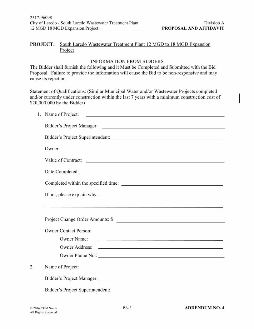
PROJECT: South Laredo Wastewater Treatment Plant 12 MGD to 18 MGD Expansion Project
INFORMATION FROM BIDDERSThe Bidder shall furnish the following and it Must be Completed and Submitted with the Bid Proposal. Failure to provide the information will cause the Bid to be non-responsive and may cause its rejection.
Statement of Qualifications: (Similar Municipal Water and/or Wastewater Projects completed and/or currently under construction within the last 7 years with a minimum construction cost of $20,000,000 by the Bidder)
1. Name of Project:
Bidder’s Project Manager:
Bidder’s Project Superintendent:
Owner:
Value of Contract:
Date Completed:
Completed within the specified time:
If not, please explain why:
Project Change Order Amounts: $
Owner Contact Person:
Owner Name:
Owner Address:
Owner Phone No.:
2. Name of Project:
Bidder’s Project Manager:
Bidder’s Project Superintendent:

2517-96098City of Laredo - South Laredo Wastewater Treatment Plant Division A12 MGD 18 MGD Expansion Project PROPOSAL AND AFFIDAVIT
© 2016 CDM Smith PA-4 ADDENDUM NO. 4All Rights Reserved
Owner:
Value of Contract:
Date Completed:
Completed within the specified time:
If not, please explain why:
Project Change Order Amounts: $
Owner Contact Person:
Owner Name:
Owner Address:
Owner Phone No.:
3. Name of Project:
Bidder’s Project Manager:
Bidder’s Project Superintendent:
Owner:
Value of Contract:
Date Completed:
Completed within the specified time:
If not, please explain why:
Project Change Order Amounts: $
Owner Contact Person:
Owner Name:
Owner Address:
Owner Phone No.:

2517-96098City of Laredo - South Laredo Wastewater Treatment Plant Division A12 MGD 18 MGD Expansion Project PROPOSAL AND AFFIDAVIT
© 2016 CDM Smith PA-5 ADDENDUM NO. 4All Rights Reserved
Experience Data: (Include name and attach experience record of the Proposed Project Superintendent and Proposed Project Manager for the South Laredo WWTP 12 MGD to 18 MGD Expansion Project)
1. Name of Proposed Project Manager:
2. Name of Proposed Project Superintendent:
Financial Status: A confidential financial statement shall be submitted by the apparent successful low Bidder if the Owner deems it necessary.
Subcontractors: Submit with the Bid Proposal a list of proposed Subcontractors who will perform the following work as well as list the proposed subcontractors who will perform work having a value of more than five (5) percent of the total contract amount. The information provided will be used in the evaluation of the Bidder. At a minimum, the three (3) apparent low bidders shall provide the contact person address and phone number for the subcontractor listed and five (5) references as well as the subcontractor amount. The references shall be for similar size and type of project. The references shall include name of project, Owner contact information, Engineer contact information, and General Contractor contact information. The contact information shall include name, phone number, and address. The address and phone number and the references for the subcontractor shall be submitted to the Owner and Engineer within twenty – four (24) hours of the bid opening.
Subcontractor Work to be Performed
Grading
Paving
Coatings
Electrical
Concrete
HVAC
Masonry
PCSS

2517-96098City of Laredo - South Laredo Wastewater Treatment Plant Division A12 MGD 18 MGD Expansion Project PROPOSAL AND AFFIDAVIT
© 2016 CDM Smith PA-6 ADDENDUM NO. 4All Rights Reserved
CITY OF LAREDOUTILITIES DEPARTMENT
PROJECT: South Laredo Wastewater Treatment Plant 12 MGD to 18 MGD Expansion Project
BID SCHEDULE
ItemNo.
EstimatedQuantity Unit Name of Pay Item with Unit
Bid Price Written in Words
UnitBid
(Figures)
AmountBid
(Figures)
A. LUMP SUM BASE BID WORK
1 1 L.S. Mobilization $ $
2 1 L.S. Installation of Stormwater Pollution Prevention Plan (SWPPP) control measures to comply with requirement of the SWPPP including Furnish all materials and incidents
$ $
3 5,300 L.F. Furnish all labor, equipment, materials, tools and professional engineer's services to provide trench safety (all depths and pipe sizes) in accordance with all applicable City, State and Federal laws, ordinances, rules and guidelines, complete in place $ $
4 1 L.S. Influent Pump Station. Installation of a new submersible centrifugal pump, access hatch safety nets, and new back-up control floats, and associated piping, fittings, valves, and all related electrical, instrumentation and control improvements as shown on the Drawings and specified herein excluding procurement costs for the new submersible centrifugal pump and variable speed drive described under Item 15, complete in place $ $
5 1 LS Aeration Basin Splitter Box and Aeration Basin. Construction of a new aeration basins influent splitter box and new Aeration Basin No. 3, and installation of aeration diffuser systems, and associated equipment, piping, fittings, valves, and all related structural, electrical, instrumentation and control improvements as shown on the Drawings and specified herein, complete in place $ $

2517-96098City of Laredo - South Laredo Wastewater Treatment Plant Division A12 MGD 18 MGD Expansion Project PROPOSAL AND AFFIDAVIT
© 2016 CDM Smith PA-7 ADDENDUM NO. 4All Rights Reserved
ItemNo.
EstimatedQuantity Unit Name of Pay Item with Unit
Bid Price Written in Words
UnitBid
(Figures)
AmountBid
(Figures)
6 1 LS Blowers, Blower Building and Emergency Generator. Construction of a new Blower Building to house two new aeration blowers, and installation of a new pad-mounted transformer, automatic transfer switch, and emergency generator to serve new aeration basin and blower building, and associated equipment, piping, fittings, valves, and all related architectural, structural, HVAC and plumbing, electrical, instrumentation and control improvements as shown on the Drawings and specified herein excluding procurement costs for the new aeration blowers descried under Item 16, complete in place
$ $
7 1 LS Clarifier Splitter Box and Secondary Clarifier. Construction of a new clarifier splitter box and new 115’-diamter secondary clarifier No. 4, and associated equipment, piping, fittings, valves, and all related structural, electrical, instrumentation and control improvements as shown on the Drawings and specified herein, complete in place $ $
8 1 LS RAS Pump Station. Installation of three new RAS pumps and associated piping, fittings, and valves, and all related electrical, instrumentation and control improvements as shown on the Drawings and specified herein, complete in place $ $
9 1 LS Chlorine Contact Basin and Chlorine Storage and Feed Facility. Construction of a new chlorine contact basin splitter box and new chlorine contact basins, installation of a new chlorine induction unit and back-up feed system, installation of new coarse bubble diffuser system with a new positive displacement blower, and modifications of existing chlorine storage and feed system, and associated piping, fittings, and valves, and all related structural, HVAC and plumbing, electrical, and instrumentation and control improvements as shown on the Drawings and specified herein, complete in place $ $

2517-96098City of Laredo - South Laredo Wastewater Treatment Plant Division A12 MGD 18 MGD Expansion Project PROPOSAL AND AFFIDAVIT
© 2016 CDM Smith PA-8 ADDENDUM NO. 4All Rights Reserved
ItemNo.
EstimatedQuantity Unit Name of Pay Item with Unit
Bid Price Written in Words
UnitBid
(Figures)
AmountBid
(Figures)
10 1 LS Effluent Sampling Building. Construction of an effluent sampling building to house an auto-sampler and effluent chart recorder, and associated piping, fittings, and valves, and all related architectural, structural, HVAC and plumbing, electrical, and instrumentation and control improvements as shown on the Drawings and specified herein, complete in place
$ $
11 1 LS Plant Yard Piping Improvements as shown on the Drawings and specified herein. This item shall also include temporary bypass pumping and temporary bypass air piping systems not to interrupt operation of the existing facilities, complete in place $ $
12 1 LS All miscellaneous civil and site work including grading, drainage, and utilities and other miscellaneous work as shown on the Drawings and specified herein, complete in place
$ $
13 1 LS Influent Pump Station Submersible Centrifugal Pump Equipment. Equipment supplier scope as defined on the Drawings and in Section 11317 of the Contract Specifications $253,912.00 $253,912.00
14 1 LS Aeration Blower Equipment. Equipment supplier scope as defined on the Drawings and in Section 11378 of the Contract Specifications $450,669.00 $450,669.00
TOTAL – A. LUMP SUM BASE BID PRICES $
ItemNo.
EstimatedQuantity Unit Name of Pay Item with Unit
Bid Price Written in Words
UnitBid
(Figures)
AmountBid
(Figures)
B. EXTRA UNIT PRICE WORK
15 1 LS Demolition of abandoned sludge drying beds in their entirety and associated mechanical equipment, piping, electrical components, and associated containment structure as shown on the Drawings and specified herein, complete in place $ $

2517-96098City of Laredo - South Laredo Wastewater Treatment Plant Division A12 MGD 18 MGD Expansion Project PROPOSAL AND AFFIDAVIT
© 2016 CDM Smith PA-9 ADDENDUM NO. 4All Rights Reserved
ItemNo.
EstimatedQuantity Unit Name of Pay Item with Unit
Bid Price Written in Words
UnitBid
(Figures)
AmountBid
(Figures)
16 1 LS Extra cost for furnishing a stand-by odorous positive displacement blower and piping modifications to make ready for installation by the City as specified in Specification Section 11370 $ $
17 1 L.S. Extra cost for testing non-contacting level measurement devices (radar and ultrasonic) at the influent pump station wet well and testing for primary control of influent pump operation as specified in Section 01010, 13300, 13302, 13305, and 13340, complete in place
$ $
18 1 L.S. As specified in Section 01010, 13300, 13302, 13305, and 13340, upon completion of the testing and demonstration of successful performance, substitution of one existing pressure transducers with the new radar level device, removal of the one associated stilling well, and completion of all associated electrical and instrumentation and control modifications associated with the substitution and installation shown on the Drawings and specified herein. After six months of successful operation, substitution of the remaining pressure transducer with a second radar level device, and removal of the second stilling well. Complete in place
$ $
19 1 L.S. Should the testing demonstrate better performance with the ultrasonic level device, additional cost for substitution of one existing pressure transducers with the new ultrasonic level device in lieu of a radar level device as described under Item 19, providing 120 VAC source to power the new ultrasonic level transmitter and routing the new conduit wiring for level signal to PLC-IPS. After six months of successful operation, substitution of the remaining pressure transducer with a second ultrasonic level device, providing 120VAC source to power the level transmitter and routing the new conduit wiring for level signal to PLC-IPS. Complete in place
$ $

2517-96098City of Laredo - South Laredo Wastewater Treatment Plant Division A12 MGD 18 MGD Expansion Project PROPOSAL AND AFFIDAVIT
© 2016 CDM Smith PA-10 ADDENDUM NO. 4All Rights Reserved
ItemNo.
EstimatedQuantity Unit Name of Pay Item with Unit
Bid Price Written in Words
UnitBid
(Figures)
AmountBid
(Figures)
20 1 L.S. One-year post substantial completion service contract for PCSS to provide four visits, three days each and specified services $ $
21 1 LS Effluent Pipe and Outfall Structure. Construction of a new 48-inch effluent pipe and new outfall headwall structures, associated piping and fitting, and all related structural and erosion control measures as shown on the Drawings and specified herein. $ $
TOTAL – B. EXTRA UNIT PRICE WORK PRICES $
ItemNo.
EstimatedQuantity Unit Name of Pay Item with Unit
Bid Price Written in Words
UnitBid
(Figures)
AmountBid
(Figures)
C. CASH ALLOWANCES
22 1 LS An allowance for providing Archaeological consulting services to manage, inspect, monitor and report on conditions during project construction efforts as described in Specification Section 01810.
$ 120,000.00 $ 120,000.00
23 1 L.S. An allowance for obtaining the City Building permit, including the review fee, permit fee and fire fee.
$ 20,400.00 $ 20,400.00
24 1 L.S. An allowance for miscellaneous additional related work including site civil work, piping, equipment, structural, electrical, instrumentation and control, identified in written request to the Contractor during construction; complete in place and approved by the Owner.
$ 500,000.00 $ 500,000.00
25 1 L.S. An allowance for the purchase and delivery of two (2) desktop computers, including software per City of Laredo’s specifications.
$ 10,000.00 $ 10,000.00
TOTAL – C. CASH ALLOWANCES $650,400.00

2517-96098City of Laredo - South Laredo Wastewater Treatment Plant Division A12 MGD 18 MGD Expansion Project PROPOSAL AND AFFIDAVIT
© 2016 CDM Smith PA-11 ADDENDUM NO. 4All Rights Reserved
TOTAL BID PRICE (A+B+C) $
TOTAL BID PRICE (A+B+C) WRITTEN IN WORDS:
Dollars
and Cents.
STATEMENT OF MATERIALS AND OTHER CHARGES
PROJECT: South Laredo Wastewater Treatment Plant 12 MGD to 18 MGD Expansion Project
MATERIALS INCORPORATED INTO THE PROJECT: $
ALL OTHER CHARGES: $
*TOTAL: $
*This total must agree with the total figure shown in the Item and Quantity Sheets in the bound contract.
For purposes of complying with the Texas Tax Code, the Contractor agrees that the charges for any material incorporated into the project in excess of the estimated quantity provided for herein will be no less than the invoice price for such material to the Contractor.
NOTE: ONLY THE COPY OF THIS FORM IN THE BOUND CONTRACTS IS TO BE FILLED OUT
The Bidder further agrees to pay, as Liquidated Damages, the amounts provided in Division B, Section 1 for failure to Substantially Complete and/or have Totally Complete and ready for Final Payment within the specified completion times.
BIDDER must answer the following questions (refer to INSTRUCTIONS FOR BIDDERS for definitions):
A. Is the bidder that is making and submitting this bid a "RESIDENT BIDDER" or a "NONRESIDENT BIDDER?
Answer:
B. If the bidder is a "NONRESIDENT BIDDER", does the State in which the Nonresident Bidder's principal place of business is located have a law requiring a Nonresident Bidder of that State to

2517-96098City of Laredo - South Laredo Wastewater Treatment Plant Division A12 MGD 18 MGD Expansion Project PROPOSAL AND AFFIDAVIT
© 2016 CDM Smith PA-12 ADDENDUM NO. 4All Rights Reserved
bid a certain amount or percentage under the bid of a Resident Bidder of that State in order for the Nonresident Bidder of that State to be awarded a contract on his bid in such State?
Answer:
C. If the answer to Question B above is "yes", then what amount or percentage must a Texas Resident Bidder bid under the bid of a Resident Bidder of that State in order to be awarded a contract on such bid in said State?
Answer:
Contractor
Signature Title
Address City/State Zip Code
Telephone Number:
Fax Number:
Date:
NOTE: ALL BID ITEMS WILL BE PAID FOR WHEN COMPLETE IN PLACE, TESTED, AND ACCEPTED BY THE OWNER.

2517-96098City of Laredo - South Laredo Wastewater Treatment Plant Division A12 MGD 18 MGD Expansion Project PROPOSAL AND AFFIDAVIT
© 2016 CDM Smith PA-13 ADDENDUM NO. 4All Rights Reserved
SCHEDULE OF MANUFACTURERS AND SUPPLIERS
The Contract Documents are based upon the equipment or products available from the manufactures / suppliers denoted as “A”, “B”, etc., below. Provision is made in the Contract Documents for the alternate manufacturers and suppliers whose equipment or product may be deemed equivalent in quality. However, the Bidder must indicate in his Bid which manufacturer/supplier he based his bid upon and which he intends to use for each item of equipment, listed below by circling one of the listed suppliers / manufacturers. If the Bidder fails to indicate which listed supplier/manufacturer he intends to use, the Bidder must use the supplier/manufacturer listed as “A”.
If the Bidder desires to propose one or more alternate suppliers/ manufacturers, he may write in (or circle if names are provided) the name of such alternates in the spaces provided on the pages following the lists below, but he must nevertheless also circle one of the listed suppliers/manufacturers because Total Base Bid must be based upon this list. Wherever an alternate supplier is proposed, the Bidder must insert the amount to be deducted from the Contract Price (either lump sum or unit price) if the alternate supplier is eventually approved.
If the proposed alternate supplier is determined "not equivalent" by the Engineer, the Bidder must use the circled supplier. If the Bidder fails to indicate which listed supplier/manufacturer he intends to use if an alternate is rejected, he must use the supplier listed as "A". Also, if the Bidder circles more than one listed supplier, he must use the first supplier circled (unless an alternate is approved).
For any alternate supplier accepted by the Owner, the Contract Price will be reduced by the deductive mount stated in the Bid. However, because the Contract Price is based on listed suppliers / manufacturers it will not be adjusted for any alternate supplier rejected.
The deductive amount specified for alternate suppliers / manufacturers will not be used in determining the successful Bidder. Alternates will be considered only after award of the contract.
In addition to the reimbursement due to the deduct, the Contractor shall also reimburse the Owner for any other costs directly attributable to the change in suppliers, such as additional field trips for the Engineer, additional redesign costs, additional review and inspection costs, modifications to structures or piping systems or other parts of the work, etc.
The Owner may request and the Bidder shall supply complete information on proposed alternates prior to the Notice of Award.

2517-96098City of Laredo - South Laredo Wastewater Treatment Plant Division A12 MGD 18 MGD Expansion Project PROPOSAL AND AFFIDAVIT
© 2016 CDM Smith PA-14 ADDENDUM NO. 4All Rights Reserved
Amount to Deduct From Base Bid and
Alternates Bid Items to Use Alternate
Equipment Listed
Specification Number Equipment
“Base Bid”Manufacturer or
Supplier
Alternate Manufacturer or
Supplier
DEDUCTa. Dezurik
b. Pratt
c. Clow
02640 Plug Valves
d. Valmatic
a. Clow
b. Kennedy
c. M&H
d. Mueller
02640 Resilient Seated Gate Valves
e. US Pipe
a. Hydrogateb. Rodney Hunt-Fontaine,
Inc.
c. Waterman
11203 Slide Gates
d. WACO Products, Inc. a. BJM Pump R75011217 Sump Pumpsb. Hayward Gordon
a. Westech
b. Envirodyne Systems
c. Walker
d. Envirex, Inc.
11225 Secondary Clarifiers
e. Hi-Tech
a. Ford Hall Co.11238 Algae Sweep Cleaning System b. Envirodyne Systems
Inc.11260 Chlorination
System a. Wallace and Tiernan a. Capital Controls
a. WaterChamp11261 Chemical Induction Equipment b. Gas MastRRR
a. Flowserve11311 Horizontal Non-clog Centrifugal Pumps b. Fairbanks Nijhuis
11317 Submersible Sewage Pumps a. KSB
11370 Positive a. Gardner-Denver

2517-96098City of Laredo - South Laredo Wastewater Treatment Plant Division A12 MGD 18 MGD Expansion Project PROPOSAL AND AFFIDAVIT
© 2016 CDM Smith PA-15 ADDENDUM NO. 4All Rights Reserved
Specification Number Equipment
“Base Bid”Manufacturer or
Supplier
Alternate Manufacturer or
Supplier
Amount to Deduct From Base Bid and
Alternates Bid Items to Use Alternate
Equipment ListedDEDUCT
Displacement Blowers b. Aerzen
a. Xylem-Sanitaire
b. Stamford Scientific
11376 Fine Bubble Fixed-Grid Aeration System
c. EDI
a. Xylem-Sanitaire
b. EDI
11377 Coarse Bubble Fixed-Grid Diffused Aeration System
c. Stamford Scientific11378 Turbo
Centrifugal Air Blowers and Appurtenances a. Sulzer ABS
a. Cummins
b. Caterpillar
11395 Diesel Engine Driven Emergency Generator
c. Kohler13300 Process Control
System Supplier a. Prime Controls
a. Dezurik
b. Pratt
c. Clow
15100 Plug Valves
d. Valmatic
a. APCO
b. Golden Anderson
c. Clow
15100 Check Valves
d. Mueller
a. Dezurik
b. Pratt
15100 Butterfly Valves for Water Service
c. Mueller
a. Dezurik
b. Keystone
15100 Butterfly Valves for Air Service 8” and Larger
c. Crane
a. American Darling15100 Gate Valves 3” and Larger
b. Kennedy

2517-96098City of Laredo - South Laredo Wastewater Treatment Plant Division A12 MGD 18 MGD Expansion Project PROPOSAL AND AFFIDAVIT
© 2016 CDM Smith PA-16 ADDENDUM NO. 4All Rights Reserved
Specification Number Equipment
“Base Bid”Manufacturer or
Supplier
Alternate Manufacturer or
Supplier
Amount to Deduct From Base Bid and
Alternates Bid Items to Use Alternate
Equipment ListedDEDUCT
c. M & H
d. Clow
a. Square D
b. Siemens Corp Robicon
c. Allen Bradley
d. General Electric
16482 Variable Frequency Drive Controllers
e. Cutler – Hammer

2517-96098City of Laredo - South Laredo Wastewater Treatment Plant Division A12 MGD 18 MGD Expansion Project PROPOSAL AND AFFIDAVIT
© 2016 CDM Smith PA-17 ADDENDUM NO. 4All Rights Reserved
ALTERNATE MANUFACTURERS / SUPPLIERS
Bidder proposes the following alternate manufacturers / suppliers for the equipment or material categories so identified:
Equipment Item or Material
Drawing No.
Spec. Section Alternative Manufacturer / Supplier (List One Only)
Deductible Amount (Indicate whether lump sum or unit
price)1.
2.
3.
4.
5.
6.
7.
8.
9.
10.
11.
12.
13.
14.
15.
16.
17.
18.
19.
20.
END OF SECTION

2517-96098 City of Laredo - South Laredo Wastewater Treatment Plant Division A
12 MGD to 18 MGD Expansion Project CONSTRUCTION CONTRACT
© 2016 CDM Smith CC-1 ADDENDUM NO. 4
All Rights Reserved
CONSTRUCTION CONTRACT
Agenda Item: _____________ STATE OF TEXAS
COUNTY OF WEBB
THIS AGREEMENT, made this day of by and between the
City of Laredo, Texas, acting by and through its duly authorized City Manager hereinafter termed the
Owner, and of the City of , County of
, State of , his/their executors, administrators, heirs,
successors, or assigns, hereinafter termed the Contractor.
WHEREAS, the Owner desired to enter into Contract for the South Laredo Wastewater Treatment Plant
12 MGD to 18 MGD Expansion in accordance with the provisions of the Invitation for Bids, the
Specifications and Plans titled as above, and published by City of Laredo, Texas, 1110 Houston Street,
(mailing address: P.O. Box 579), Laredo, Texas 78040 all of which are a part thereof; and,
WHEREAS, the Contractor has been engaged in and now does such work and represents that he is fully
equipped, competent and capable to perform the above desired and outlined work, and is ready and
willing to perform the work in accordance with the provisions of the Invitation for Bids, the
Specifications and Plans, titled, "South Laredo Wastewater Treatment Plant 12 MGD to 18 MGD
Expansion Project.”
WITNESS:
THAT for and in consideration of the payments and agreements hereinafter mentioned to be made and
performed by the Owner, the Contractor hereby agrees at the unit price set forth in his Bid, made a part
thereof totaling the sum of _____________________________________________ ($______________)
based on the Engineer's estimate of quantities, payable in the manner set out in Division C, Section 9,
General Provisions of the contractual Documents to commence and complete the South Laredo
Wastewater Treatment Plant 12 MGD to 18 MGD Expansion Project in the City of Laredo, Tx, in
accordance with Instructions to Bidders, Special Provisions, General Provisions, Technical Provisions,
and all other requirements of the contractual Documents, and in accordance with the Specifications and
Plans (including all maps, plats, blueprints, and other drawings and printed or written explanatory matter
thereof) prepared by the Owner's Engineer, a part thereof and collectively, together with this Agreement
constitute the entire Contract; and the Contractor agrees to furnish all the materials, supplies, machinery,
equipment, tools, superintendence, labor, insurance, and other insurance and other accessories and
services, and whatever else may be necessary to complete the said construction in accordance with said
specifications, plans, and other contractual documents including such proposal.
Said Contractor further agrees to begin the work on or before the tenth day following the date set by the
Owner in the written notice to proceed and to substantially complete the work within 730 calendar days
and 775 calendar days to final project completion.
The Contractor further agrees to pay, as liquidated damages, the sum of $ 1,500 for each calendar day
that the Plant Expansion Facilities are not Substantially Completed within the time specified, and the
sum of $ 500 for each calendar day that the work is not totally complete and ready for Final Payment as
herein provided in Division B.

2517-96098 Division BCity of Laredo - South Laredo Wastewater Treatment Plant CONTRACT TIME AND12 MGD to 18 MGD Expansion Project LIQUIDATED DAMAGES
© 2016 CDM Smith CT-1 ADDENDUM NO. 4All Rights Reserved
SECTION 1
CONTRACT TIME AND LIQUIDATED DAMAGES
Project: South Laredo Wastewater Treatment Plant 12 MGD to 18 MGD Expansion Project
A. Completion Time
The Contract Time for substantial completion for this project including all the work specified herein and shown on the Drawings shall be 730 Calendar Days from the Notice to Proceed. The Contract Time for Total Completion and ready for Final Payment for all work shall be 775 Calendar Days from the Notice to Proceed.
B. Liquidated Damages
Owner and Contractor recognize that time is of the essence for this Contract and that the Owner will suffer financial loss if the Work is not completed within the times specified above and in the Construction Contract, plus any extensions thereof allowed in accordance with the Contract Documents. They also recognize the delays, expense and difficulties involved in proving in a legal proceeding the actual loss suffered by Owner if the Work is not completed on time. Accordingly, instead of requiring any such proof, Owner and Contractor agree that as Liquidated Damages for delay (but not as a penalty) Contractor shall pay Owner Liquidated Damages as defined below:
If Contractor should neglect, fail, or refuse to Substantially Complete the Plant Expansion Facilities work within the time herein specified, or any proper extension thereof granted by the Owner, then the Contractor does hereby agree as part of the consideration for awarding of this contract, that the Owner may withhold permanently from the Contractor’s total compensation the sum of Fifteen Hundred Dollars ($1500.00) for each and every Calendar Day that the Contractor shall be in default after the time stipulated for Substantially Completing the work, not as a penalty, but as Liquidated Damages for the breach in contract.
If Contractor should neglect, fail, or refuse to complete the work within the time herein specified for having the work Totally Complete and ready for Final Payment, or any proper extension thereof granted by the Owner, then the Contractor does hereby agree as part of the consideration for awarding this contract, that the Owner may withhold permanently from the Contractor’s total compensation the sum of Five Hundred Dollars $500.00 for each any every Calendar Day that the Contractor shall be in default after the time stipulated for the work to be Totally Complete and ready for Final Payment, not as a penalty, but as Liquidated Damages for the breach in contract.

2517-96098City of Laredo - South Laredo Wastewater Treatment Plant Division 0312 MGD to 18 MGD Expansion Project CAST-IN-PLACE CONCRETE
© 2016 CDM Smith 03300-1 ADDENDUM NO. 4All Rights Reserved
SECTION 03300CAST-IN-PLACE CONCRETE
PART 1: GENERAL
1.01 SCOPE OF WORK
A. Furnish all labor, materials, equipment, and incidentals required and install cast-in-place concrete complete as shown on the Drawings and as specified herein.
B. Furnish, as required to establish concrete mixes, all sampling and laboratory testing of products and materials performed by an independent testing laboratory engaged by and at the expense of the Contractor. Field sampling, testing, inspection and related laboratory tests will be provided by the Owner.
1.02 MEASUREMENT AND PAYMENT
A. No separate payment will be made for work performed under this Section. Include the cost for this work in the lump sum Base Bid.
1.03 RELATED WORK
A. Watertightness test for water containing structures is included in Section 01680.
B. Concrete formwork is included in Section 03100.
C. Concrete reinforcement is included in Section 03200.
D. Concrete joints and joint accessories are included in Section 03250.
E. Concrete finishes are included in Section 03350.
F. Grout is included in Section 03600.
G. Modifications to existing concrete are included in Section 03740.
H. Concrete electrical raceway encasement is included in Section 03800.
I. Miscellaneous metals are included in Section 05500.
J. Waterproofing, dampproofing, and caulking are included in Section 07005.
1.04 SUBMITTALS
A. Submit, in accordance with Section 01300, product data for:
1. Sources of cement, fly ash, aggregates, and batched concrete. Indicate name and address of mill or quarry, as applicable.

2517-96098City of Laredo - South Laredo Wastewater Treatment Plant Division 0312 MGD to 18 MGD Expansion Project CAST-IN-PLACE CONCRETE
© 2016 CDM Smith 03300-2 ADDENDUM NO. 4All Rights Reserved
2. Water reducing admixture. Product data including catalogue cut, technical data, storage requirements, product life, recommended dosage, temperature considerations and conformity to ASTM standards.
3. Sheet curing material. Product data including catalogue cut, technical data and conformity to ASTM standard.
4. Material Safety Data Sheets (MSDS) for all concrete components and admixtures.
5. Cold weather and hot weather concreting plans demonstrating how concrete will meet the requirements of this Section including but not limited to concrete mixes, placement, curing and protection.
6. High-range water-reducing admixture (plasticizer). Product data including catalogue cut, technical data, storage requirements, product life, recommended dosage, temperature considerations, retarding effect, slump range and conformity to ASTM standards. Identify proposed locations of use.
7. Liquid membrane forming curing compound. Product data including catalogue cut, technical data, storage requirements, product life, application rate and conformity to ASTM standards. Identify proposed locations of use.
8. Coloring admixture. Product data including catalogue cut, technical data, storage requirements, product life, recommended dosage, temperature considerations and conformity to ASTM standards.
B. Samples
1. Fine and coarse aggregates if requested for examination by the Engineer.
C. Test Reports
1. Aggregates: Conformance to ASTM standards, including sieve analysis, mechanical properties, deleterious substance content, and mortar bar expansion test results.
2. Cement and fly ash: Conformance to ASTM standards, including chemical analysis and physical tests.
3. Concrete mixes: For each formulation of concrete proposed for use, submit constituent quantities per cubic yard, water cementitious ratio, concrete slump, type and manufacturer of cement and type and manufacturer of fly ash. Provide either Paragraph a. or b., below, for each mix proposed.
a. Standard deviation data for each proposed concrete mix based on statistical records.
b. Provide the following for each strength data point used in the calculation of the standard deviation for determination of the minimum required average strength:
1) Date of sampling and name of testing laboratory.

2517-96098City of Laredo - South Laredo Wastewater Treatment Plant Division 0312 MGD to 18 MGD Expansion Project CAST-IN-PLACE CONCRETE
© 2016 CDM Smith 03300-3 ADDENDUM NO. 4All Rights Reserved
2) Name of concrete batch plant.
3) Water cementitious ratio.
4) Slump of batch.
5) Compressive strengths of all cylinders tested at that age in that batch.
6) If available, temperature and unit weight of batch.
7) Provide data from projects not more strictly controlled than outlined in these specifications. Provide summary sheet showing all pertinent data and the computation of the standard deviation.
c. Water cementitious ratio curve for concrete mixes based on laboratory tests. Provide average cylinder strength test results at 7, 14, and 28 days for laboratory concrete mix designs.
4. Certifications
5. Certify that admixtures used in the same concrete mix are compatible with each other and the aggregates.
6. Certify that the Contractor is not associated with the independent testing laboratory proposed for use by the Contractor nor does the Contractor or officers of the Contractor's organization have a beneficial interest in the laboratory.
7. Certificate of conformance for concrete production facilities from the NRMCA.
D. Qualifications
1. Independent Testing Laboratory
a. Name and address
b. Names and positions of principal officers and the name, position, and qualifications of the responsible registered professional engineer in charge.
c. Listing of technical services to be provided. Indicate external technical services to be provided by other organizations.
d. Names and qualifications of the supervising laboratory technicians.
e. Statement of conformance provided by evaluation authority defined in ASTM C1077. Provide report prepared by evaluation authority when requested by the Engineer.
f. Submit as required above for other organizations that will provide external technical services.

2517-96098City of Laredo - South Laredo Wastewater Treatment Plant Division 0312 MGD to 18 MGD Expansion Project CAST-IN-PLACE CONCRETE
© 2016 CDM Smith 03300-4 ADDENDUM NO. 4All Rights Reserved
1.05 REFERENCE STANDARDS
A. ASTM International
1. ASTM C31 - Standard Practice for Making and Curing Concrete Test Specimens in the Field.
2. ASTM C33 - Standard Specification for Concrete Aggregates.
3. ASTM C39 - Standard Test Method for Compressive Strength of Cylindrical Concrete Specimens.
4. ASTM C42 - Standard Test Method for Obtaining and Testing Drilled Cores and Sawed Beams of Concrete.
5. ASTM C94 - Standard Specification for Ready-Mixed Concrete.
6. ASTM C138 – Standard Test Method for Density (Unit Weight), Yield, and Air Content (Gravimetric) of Concrete.
7. ASTM C143 - Standard Test Method for Slump of Hydraulic-Cement Concrete
8. ASTM C150 - Standard Specification for Portland Cement
9. ASTM C156 - Standard Test Method for Water Retention by Liquid Membrane-Forming Curing Compound for Concrete
10. ASTM C157 - Standard Test Method for Length Change of Hardened Hydraulic-Cement Mortar and Concrete.
11. ASTM C171 - Standard Specification for Sheet Materials for Curing Concrete
12. ASTM C192 – Standard Practice for Making and Curing Concrete Test Specimens in the Laboratory.
13. ASTM C309 - Standard Specification for Liquid Membrane-Forming Compounds for Curing Concrete.
14. ASTM C311 - Standard Test Methods for Sampling and Testing Fly Ash or Natural Pozzolans for use in Portland Cement Concrete.
15. ASTM C494 - Standard Specification for Chemical Admixtures for Concrete.
16. ASTM C596 - Standard Test Method for Drying Shrinkage of Mortar Containing Hydraulic Cement.
17. ASTM C618 - Standard Specification for Coal Fly Ash and Raw or Calcined Natural Pozzolan for Use in Concrete.
18. ASTM C979 – Specification for Pigments for Integrally Colored Concrete.

2517-96098City of Laredo - South Laredo Wastewater Treatment Plant Division 0312 MGD to 18 MGD Expansion Project CAST-IN-PLACE CONCRETE
© 2016 CDM Smith 03300-5 ADDENDUM NO. 4All Rights Reserved
19. ASTM C1077 - Standard Practice for Laboratories Testing Concrete and Concrete Aggregates for Use in Construction and Criteria for Laboratory Evaluation.
20. ASTM C1218 - Standard Test Method for Water-Soluble Chloride in Mortar and Concrete.
21. ASTM C1260 - Standard Test Method for Potential Alkali Reactivity of Aggregates (Mortar-Bar Method).
22. ASTM E329 - Standard Specification for Agencies Engaged in Construction Inspection and/or Testing.
B. American Concrete Institute (ACI)
1. ACI 211.1 - Standard Practice for Selecting Proportions for Normal, Heavyweight and Mass Concrete.
2. ACI 232.2R - Use of Fly Ash in Concrete.
3. ACI 304R - Guide for Measuring, Mixing, Transporting and Placing Concrete.
4. ACI 304.2R - Placing Concrete by Pumping Methods.
5. ACI 305R - Hot Weather Concreting.
6. ACI 306R - Cold Weather Concreting.
7. ACI 318 - Building Code Requirements for Structural Concrete and Commentary.
8. ACI 350 - Code Requirements for Environmental Engineering Concrete Structures and Commentary.
C. National Ready Mixed Concrete Association (NRMCA)
1. Quality Control Manual, Section 3 - Certification of Ready Mixed Concrete Production Facilities.
D. Truck Mixer Manufacturers Bureau (TMMB)
1. TMMB 100 - Truck Mixer, Agitator and Front Discharge Concrete Carrier Standards.
E. Where reference is made to one of the above standards, the revision in effect at the time of bid opening shall apply.
1.06 QUALITY ASSURANCE
A. Comply with ACI 350 and other stated specifications, codes and standards. Apply the most stringent requirements of other stated specifications, codes, standards, and this Section when conflicts exist.

2517-96098City of Laredo - South Laredo Wastewater Treatment Plant Division 0312 MGD to 18 MGD Expansion Project CAST-IN-PLACE CONCRETE
© 2016 CDM Smith 03300-6 ADDENDUM NO. 4All Rights Reserved
B. Independent testing laboratory shall meet the requirements of ASTM E329 and ASTM C1077 and be acceptable to the Engineer. Laboratories affiliated with the Contractor or in which the Contractor or officers of the Contractor's organization have a beneficial interest are not acceptable.
C. Use only one source of cement and aggregates for the project. Provide concrete uniform in color and appearance.
D. At least 10 working days before the first concrete placement, hold a preconstruction meeting to review the requirements for concrete placement, waterstop placement, jointing, concrete curing, hot weather concreting, cold weather concreting and finishing. Review, with the attendance of the plasticizer manufacturer, the properties and techniques of batching and placing concrete containing high-range water-reducing admixture. Notify all parties involved, including the Engineer, of the meeting at least ten working days prior to its scheduled date. Prepare an agenda for the meeting. Take meeting minutes and distribute to all attendees.
E. If, during the progress of the work, it is impossible to secure concrete of the specified workability and strength with the materials being furnished, the Engineer may order such changes in proportions or materials, or both, as may be necessary to secure the specified properties. Make all changes so ordered at no additional cost to the Owner.
F. If, during the progress of the work, the materials from the sources originally accepted change in characteristics, make, at no additional cost to the Owner, new acceptance tests of materials and establish new concrete mixes with the assistance of an independent testing laboratory.
G. All field testing and inspection services and related laboratory tests required will be provided by the Owner. The cost of such work will be paid for by the Owner. Methods of testing will comply with the latest applicable ASTM methods.
H. Samples of constituents and of concrete as-placed will be subjected to laboratory tests by the Owner. All materials incorporated in the work shall conform to accepted samples.
1.07 DELIVERY, STORAGE, AND HANDLING
A. Cement: Store in weathertight buildings, bins or silos to provide protection from dampness and contamination and to prevent warehouse set.
B. Aggregate: Arrange and use stockpiles to prevent segregation or contamination with other materials or with other sizes of like aggregates. Build stockpiles in successive horizontal layers not exceeding three feet in thickness. Complete each layer before the next is started. Do not use frozen or partially frozen aggregate.
C. Sand: Arrange and use stockpiles to prevent contamination. Allow sand to drain to a uniform moisture content before using. Do not use frozen or partially frozen sand.
D. Admixtures: Store in closed containers to prevent contamination, evaporation or damage. Provide agitating equipment to uniformly disperse ingredients in admixture solutions which tend to separate. Protect liquid admixtures from freezing and other temperature changes which could adversely affect their characteristics.

2517-96098City of Laredo - South Laredo Wastewater Treatment Plant Division 0312 MGD to 18 MGD Expansion Project CAST-IN-PLACE CONCRETE
© 2016 CDM Smith 03300-7 ADDENDUM NO. 4All Rights Reserved
E. Fly Ash: Store in weathertight buildings, bins or silos to provide protection from dampness and contamination.
F. Sheet Curing Materials: Store in weathertight buildings or off the ground and under cover.
G. Liquid Membrane Forming Curing Compounds: Store in closed containers.
PART: PRODUCTS
2.01 GENERAL
A. The use of manufacturer's name and model or catalog number is for the purpose of establishing the standard of quality and general configuration desired.
B. Like items of materials shall be the end products of one manufacturer in order to provide standardization for appearance, maintenance and manufacturer's service.
2.02 MATERIALS
A. Materials shall comply with this Section and any applicable State or local requirements.
B. Cement: Domestic Portland cement conforming to ASTM C150. Cement shall be low alkali cement. Do not use air entraining cements. Cement brand must be approved by the Engineer and one brand shall be used throughout the work. Provide the following type(s) of cement:
1. All Class of Concrete - Type I/II
C. Aggregates:
1. Fine Aggregate: Washed inert natural sand conforming to ASTM C33.
2. Coarse Aggregate: Well-graded crushed stone or washed gravel conforming to ASTM C33. Grading requirements as listed in ASTM C33, Table 2 for the specified coarse aggregate size number listed in Table 1 herein. Limits of deleterious substances and physical property requirements as listed in ASTM C33, Table 3 for severe weathering regions. Do not use coarse aggregates known to be deleteriously reactive with alkalis in cement.
3. The fine and coarse aggregates used shall not cause expansion of mortar bars greater than 0.1 percent in 16 days when tested in accordance with ASTM C1260 and using the cement proposed for the project. If aggregates proposed for use do not meet this requirement, then satisfy either a or b below.
a. Total equivalent alkali content of the cement used shall not exceed 0.60 percent as provided in the Optional Chemical Requirements of ASTM C150.
b. The fine and coarse aggregates used shall not cause expansion of mortar bars greater than 0.1 percent in 16 days when tested in accordance with ASTM C1260 and using the cement and fly ash proposed for the project. The proportions of the cement-fly ash mix shall be the same as those proposed for the project.

2517-96098City of Laredo - South Laredo Wastewater Treatment Plant Division 0312 MGD to 18 MGD Expansion Project CAST-IN-PLACE CONCRETE
© 2016 CDM Smith 03300-8 ADDENDUM NO. 4All Rights Reserved
D. Water: Potable water free of oil, acid, alkali, salts, chlorides (except those attributable to drinking water), organic matter, or other deleterious substances.
E. Admixtures: Use admixtures free of chlorides and alkalis (except for those attributable to drinking water). The admixtures shall be from the same manufacturer when it is required to use more than one admixture in the same concrete mix. Use admixtures compatible with the concrete mix including other admixtures.
1. Water Reducing and Retarding Admixture: Conforming to ASTM C494, Type B and D. Proportion and mix in accordance with manufacturer's recommendations.
2. Water Reducing Admixture: Conforming to ASTM C494, Type A. Proportion and mix in accordance with manufacturer's recommendations.
3. High-Range Water-Reducing Admixtures (Plasticizer): Conforming to ASTM C494, Type F or ASTM C1017, Type I resulting in non-segregating plasticized concrete with little bleeding and with the physical properties of low water/cementitious ratio concrete. The treated concrete shall be capable of maintaining its plastic state in excess of two hours. Proportion and mix in accordance with manufacturer's recommendations.
4. Do not use admixtures causing accelerated setting of concrete without written approval from the Engineer. Use accelerating water reducing admixtures when so approved.
5. Coloring Admixture (for concrete electrical raceway encasement only): ASTM C979, synthetic or natural mineral oxide pigments or colored water reducing admixture, temperature stable and non-fading. Proportion and mix in accordance with manufacturer’s recommendations. Coloring admixture shall be compatible with all other admixtures. The maximum prescribed dosage rate of a pigment established in accordance with ASTM C979 shall be equal to or less than 10% mass of cement.
F. Fly Ash: Class F fly ash complying with ASTM C618, including the requirements of Table 1 but with the Loss on Ignition (LOI) limited to 3 percent maximum and the optional physical requirements of Table 3. Test in compliance with ASTM C311 with a minimum of one sample weighing four pounds taken from each 200 tons of fly ash supplied for the project.
G. Sheet Curing Materials: Waterproof paper, polyethylene film or white burlap-polyethylene sheeting, all conforming to ASTM C171.
H. Liquid Membrane-Forming Curing Compound. Compound conforming to ASTM C309, Type 1-D (clear or translucent with fugitive dye) and containing no wax, paraffin, or oil. Curing compounds shall be non-yellowing and have a unit moisture loss no greater than 0.039 gm/cm2 at 72 hours as measured by ASTM C156. Curing compound shall comply with Federal, State and local VOC limits.
2.03 MIXES
A. An independent testing laboratory engaged by and at the expense of the Contractor shall establish concrete mixes and perform all sampling and laboratory testing of products and materials.

2517-96098City of Laredo - South Laredo Wastewater Treatment Plant Division 0312 MGD to 18 MGD Expansion Project CAST-IN-PLACE CONCRETE
© 2016 CDM Smith 03300-9 ADDENDUM NO. 4All Rights Reserved
B. Select proportions of ingredients to meet the design strength and materials limits specified in Table 1 and to produce placeable, durable concrete conforming to these specifications. Proportion ingredients to produce a homogenous mixture which will readily work into corners and angles of forms and around reinforcement without permitting materials to segregate or allowing free water to collect on the surface.
C. Base concrete mixes on standard deviation data of prior mixes with essentially the same proportions of the same constituents or, if not available, develop concrete mixes by laboratory tests using the materials proposed for the work.
1. For concrete mixes based on standard deviation data of prior mixes, submit standard deviation data of prior mixes with essentially the same proportions of the same constituents in accordance with ACI350 and based on the modification factors for standard deviation tests contained in ACI 350.
2. For concrete mixes developed by laboratory testing, base cementitious content of the concrete on curves showing the relation between water cementitious ratio and 7, 14 and 28 day compressive strengths of concrete made using the proposed materials. Determine curves by four or more points, each representing an average value of at least three test specimens and one water-cementitious ratio at each age. Provide curves with a range of values sufficient to yield the desired data, including the compressive strengths specified, without extrapolation. The cementitious content of the concrete mixes to be used, as determined from the curve, shall correspond to the required average compressive strength in Table 5.3.2.2 of ACI 350. The resulting mix shall not conflict with the limiting values for maximum water cementitious ratio and net minimum cementitious content specified in Table 1.
D. Test the fly ash and concrete mixture to provide test data confirming that the fly ash in combination with the cement to be used meets all strength requirements and is compatible with the other concrete additives.
E. Test aggregates for potential alkali reactivity in accordance with ASTM C1260. If initial testing indicates aggregates are not potentially reactive repeat test at 3 month intervals.
F. Compression Tests: Provide testing of the proposed concrete mixes to demonstrate compliance with the compression strength requirements in conformity with the provisions of ACI 318.
G. Slump of the concrete as measured by ASTM C143, shall be as shown in Table 1. If a high-range water-reducing admixture (plasticizer) is used, the slump indicated shall be that measured before plasticizer is added. Plasticized concrete shall have a slump ranging from seven to ten inches.
H. Proportion admixtures according to the manufacturer's recommendations. Two or more admixtures specified may be used in the same mix provided that the admixtures in combination retain full efficiency and have no deleterious effect on the concrete or on the properties of the other admixture(s).
I. Shrinkage Tests: Perform shrinkage tests on the design mix for Class Class D concrete. The tests shall conform to ASTM C157 as modified by ASTM C596. Use concrete specimens. Do not use mortar specimens.

2517-96098City of Laredo - South Laredo Wastewater Treatment Plant Division 0312 MGD to 18 MGD Expansion Project CAST-IN-PLACE CONCRETE
© 2016 CDM Smith 03300-10 ADDENDUM NO. 4All Rights Reserved
1. The average shrinkage at 25 days of air storage shall not exceed 0.036 percent.
TABLE 1Design Fine Coarse Cementitious
Class Strength Cement Aggregate Aggregate Content1 2 3 3 4
A 2500 Type II Sand 57 (9) 440B 3000 Type II Sand 57 480D2 4000 Type II Sand 57 560
W/C AE SlumpClass Ratio Fly Ash Range WR HRWR Range
5 6 7 8 10 Inches
A 0.62 max. Yes - Yes Yes 1-4B 0.54 max. Yes - Yes Yes 1-3D2 0.44 max. Yes - Yes Yes 3-5
TABLE NOTES:1. Minimum compressive strength in psi at 28 days2. ASTM designation in ASTM C1503. Size Number in ASTM C334. Minimum cementitious content in lbs per cubic yard (where fly ash is used cementitious
content is defined as cement content plus fly ash content)5. W/C is Maximum Water Cementitious ratio by weight6. Fly ash content in the range of 20-25 percent of the total cement content plus fly ash
content, by weight7. AE is percent air entrainment8. WR is water reducing admixture9. Except as specified in Section 03800 for concrete electrical raceway encasement10. HRWR is high-range water-reducing admixture
PART 3: EXECUTION
3.01 MEASURING MATERIALS
A. Provide concrete composed of Portland cement, fly ash, fine aggregate, coarse aggregate, water and admixtures as specified and produced by a plant complying with ACI 318 and ASTM C94. Batch all constituents, including admixtures, at the plant. High-range water reducing admixtures may be added in the field.
B. Measure materials for batching concrete by weighing in conformity with and within the tolerances given in ASTM C94 except as otherwise specified. Use scales last certified by the local Sealer of Weights and Measures within one year of use.
C. Weigh cement and fly ash in individual weigh batchers that are separate and distinct from the weigh batchers used for other materials. When cement and fly ash are weighed in a cumulative weigh batcher, the cement shall be weighed first.

2517-96098City of Laredo - South Laredo Wastewater Treatment Plant Division 0312 MGD to 18 MGD Expansion Project CAST-IN-PLACE CONCRETE
© 2016 CDM Smith 03300-11 ADDENDUM NO. 4All Rights Reserved
D. Measure the amount of free water in fine aggregates within 0.5 percent with a moisture meter. Compensate for varying moisture contents of fine aggregates. Record the number of gallons of water as-batched on printed batch tickets.
E. Dispense admixtures either manually using calibrated containers or measuring tanks, or by means of an automatic dispenser approved by the manufacturer of the specific admixture.
1. Charge chemical admixtures into the mixer as a solution using an automatic dispenser or similar metering device.
2. Inject multiple admixtures separately during the batching sequence.
3.02 MIXING AND TRANSPORTING
A. Provide ready-mixed concrete produced by equipment complying with ACI 318 and ASTM C94 and produced by a plant certified by the NRMCA. Do not hand-mix. All truck mixers shall carry a rating plate conforming to TMMB 100. Clean each transit mix truck drum and reverse drum rotation before the truck proceeds under the batching plant. Equip each transit-mix truck with a continuous, nonreversible, revolution counter showing the number of revolutions at mixing speeds.
B. Transport ready-mix concrete to the site in watertight agitator or mixer trucks loaded not in excess of their rated capacities as stated on the name plate.
C. Keep the water tank valve on each transit truck locked at all times. Any addition of water must be directed by the concrete supplier quality personel and shall be approved by the Engineer. Incorporate water directed to be added by additional mixing of at least 50 revolutions at mixing speed after the addition of all water. Meter all added water and show the amount of water added on each delivery ticket.
D. Comply with ACI 318 and ASTM C94 for all central plant and rolling stock equipment and methods.
E. Select equipment of size and design to provide continuous flow of concrete at the delivery end. Use metal or metal-lined non-aluminum discharge chutes with slopes not exceeding one vertical to two horizontal and not less than one vertical to three horizontal. Chutes more than 20-ft long and chutes not meeting slope requirements may be used if concrete is discharged into a hopper before distribution.
F. Do not re-temper (mix with or without additional cement, aggregate, or water) concrete or mortar which has partially hardened.
G. Handle concrete from mixer to placement providing concrete of specified quality in the placement area and not exceeding the maximum time interval specified in Paragraph 3.02 I.4. Dispatch trucks from the batching plant so they arrive at the work site just before the concrete is required to avoid excessive mixing of concrete while waiting or delays in placing successive layers of concrete in the forms. Remix for a minimum of 5 minutes prior to discharge or testing.
H. Furnish a delivery ticket for ready mixed concrete to the Engineer as each truck arrives. Provide a printed record of the weight of cement and each aggregate as batched individually on each ticket.

2517-96098City of Laredo - South Laredo Wastewater Treatment Plant Division 0312 MGD to 18 MGD Expansion Project CAST-IN-PLACE CONCRETE
© 2016 CDM Smith 03300-12 ADDENDUM NO. 4All Rights Reserved
Use the type of indicator that returns for zero punch or returns to zero after a batch is discharged. Indicate for each batch the weight of fine and coarse aggregate, cement, fly ash, and water, moisture content of fine and coarse aggregate at time of batching, and types, brand and quantity of each admixture, the quantity of concrete delivered, the time any water is added and the amount, and the numerical sequence of the delivery. Show the time of day batched and time of discharge from the truck. Indicate the number of revolutions of transit mix truck.
I. Temperature and Mixing Time Control
1. In cold weather (see Paragraph 3.07D) maintain the as-mixed temperature of the concrete and concrete temperatures at the time of placement in the forms as indicated in Table 3.
2. If water or aggregate has been heated, combine water with aggregate in the mixer before cement is added. Do not add cement to mixtures of water and aggregate when the temperature of the mixture is greater than 90 degrees F.
3. In hot weather (see Paragraph 3.07E), cool ingredients before mixing to maintain temperature of the concrete below the maximum placing temperature of 90 degrees F. Well-crushed ice may be substituted for all or part of the mixing water.
4. The maximum time interval between the addition of mixing water and/or cement to the batch and the final placing of concrete in the forms shall not exceed the values shown in the following TABLE 2:
TABLE 2
AIR OR CONCRETE TEMPERATURE(WHICHEVER IS HIGHER)
MAXIMUMTIME
(27 Degree C) 80 Degree F to 90 Degree F (32 Degree C) 45 minutes(21 Degree C) 70 Degree F to 79 Degree F (26 Degree C) 60 minutes(5 Degree C) 40 Degree F to 69 Degree F (20 Degree C) 90 minutes
J. If an approved high-range water-reducing admixture (plasticizer) is used to produce plasticized concrete, the maximum time interval between the addition of mixing water and/or cement to the batch and the final placing of concrete in the forms shall not exceed 90 minutes.
K. If water reducing and retarding admixture is used to delay set time for concrete, the maximum time interval between the addition of mixing water and/or cement to the batch and the final placing of concrete in the forms shall not exceed 120 minutes.
3.03 INSPECTION AND COORDINATION
A. Batching, mixing, transporting, placing and curing of concrete shall be subject to the inspection of the Engineer at all times. Advise the Engineer of readiness to proceed at least 24 hours prior to each concrete placement. The Engineer will inspect the preparations for concreting including the preparation of previously placed concrete, the reinforcing and the alignment, cleanliness and tightness of formwork. Do not place concrete without the inspection and acceptance of the Engineer.

2517-96098City of Laredo - South Laredo Wastewater Treatment Plant Division 0312 MGD to 18 MGD Expansion Project CAST-IN-PLACE CONCRETE
© 2016 CDM Smith 03300-13 ADDENDUM NO. 4All Rights Reserved
3.04 EMBEDDED ITEMS
A. Secure to forms as required or set for embedment as required, all miscellaneous metal items, sleeves, reglets, anchor bolts, anchors, inserts and other items furnished under other Sections and required to be embedded into concrete. Set and secure such items in the locations and alignments needed so they are not displaced by concrete placement.
B. Clean embedded items free of rust, mud, dirt, grease, oil, ice, or other contaminants which would reduce or prevent bonding with concrete.
C. Coat or isolate all aluminum embedments to prevent aluminum-concrete reaction or electrolytic action between aluminum and steel.
D. Do not embed piping in concrete unless shown on the Drawings.
E. Do not embed electrical conduits in concrete unless shown on the Drawings.
F. Fabricate piping and conduit such that the cutting, bending, or relocation of reinforcing steel is not required. Pipes and conduits embedded within a slab or wall (other than those merely passing through) shall satisfy the following, unless otherwise shown on the Drawings or approved:
1. Maximum outside dimension of pipe or conduit shall not be greater than one third the overall thickness of the slab or wall.
2. Spacing of pipes or conduits shall be greater than or equal to three diameters or widths on center.
G. Close open ends of piping, conduits, and sleeves embedded in concrete with caps or plugs prior to placing concrete.
H. Ensure all specified tests and inspections on embedded piping are completed and satisfactory before starting concrete placement. Ensure all mechanical or electrical tests and inspections are completed and satisfactory prior to starting concrete placement. Do not place concrete until unsatisfactory items and conditions have been corrected.
I. Position embedded anchor bolts using templates.
J. Check location, alignment, and support of anchor bolts, piping, electrical conduits, and other items which will be fully or partially embedded in concrete before depositing concrete. Correct mis-located and misaligned items and secure items which have become loose before depositing concrete.
K. Correct all embedded items not installed in the location or alignment needed or displaced by concrete placement at no additional cost to the Owner.
3.05 CONCRETE APPEARANCE
A. Remix concrete showing either poor cohesion or poor coating of the coarse aggregate with paste. Reject remixed concrete showing either poor cohesion or poor coating of the coarse aggregate with

2517-96098City of Laredo - South Laredo Wastewater Treatment Plant Division 0312 MGD to 18 MGD Expansion Project CAST-IN-PLACE CONCRETE
© 2016 CDM Smith 03300-14 ADDENDUM NO. 4All Rights Reserved
paste. Make, at no additional cost to the Owner, changes in the concrete mix design for future deliveries only by adjusting one or more of the following if the slump is within the allowable limit, but excessive bleeding, poor workability, or poor finishability are observed:
1. The gradation of aggregate.
2. The proportion of fine and coarse aggregate.
B. Provide concrete having a homogeneous structure which, when hardened, will have the specified strength, durability and appearance. Provide mixtures and workmanship such that concrete surfaces, when exposed, will require no finishing except as specified in Section 03350.
3.06 PLACING AND COMPACTING
A. Placing
1. Verify that all formwork completely encloses concrete to be placed and is securely braced prior to concrete placement. Remove ice, standing water, dirt, debris, and other foreign materials from forms and exposed joint surfaces. Confirm that reinforcement and other embedded items are securely in place. Have a worker at the location of the placement who can check that reinforcement and embedded items remain in designated locations and alignments while concrete is being placed. Sprinkle semi-porous subgrades or forms to eliminate suction of water from the mix. Do not place concrete on frozen subgrade, snow, or ice.
2. Deposit concrete as near its final position as possible to prevent segregation due to rehandling or flowing. Place concrete continuously at a rate that allows the concrete previously placed to be integrated with fresh plastic concrete. Do not deposit concrete which has partially hardened or has been contaminated by foreign materials or on concrete which has hardened sufficiently to cause formation of seams or planes of weakness within the section. If the section cannot be placed continuously, place construction joints as specified or as approved.
3. Pumping of concrete will be permitted. Use a mix design and aggregate sizes chosen for pumping and submit for approval. Do not use pipelines made of aluminum or aluminum alloy. When concrete is pumped, slump will be determined at point of truck discharge .
4. Remove temporary spreaders from forms when the spreader is no longer needed. Temporary spreaders may remain embedded in concrete only when made of galvanized steel or concrete and if prior approval has been obtained.
5. Do not place concrete for supported elements until concrete previously placed in the supporting element has attained design strength.
6. Where surface mortar is to form the base of a finish, especially surfaces designated to be painted, work coarse aggregate back from forms to bring the full surface of the mortar against the form. Prevent the formation of surface voids.

2517-96098City of Laredo - South Laredo Wastewater Treatment Plant Division 0312 MGD to 18 MGD Expansion Project CAST-IN-PLACE CONCRETE
© 2016 CDM Smith 03300-15 ADDENDUM NO. 4All Rights Reserved
7. Slabs
a. After bulkheads, screeds and jointing materials have been positioned, place concrete continuously between joints beginning at a bulkhead, edge form, or corner. Place each batch into the edge of the previously placed concrete to avoid stone pockets and segregation.
b. Avoid delays in placement. If there is a delay in placement, spade and consolidate the concrete placed after the delay at the edge of the previously placed concrete to avoid cold joints. Bring concrete to correct level and strike off with a straightedge. Use bull floats or darbies to smooth the surface, leaving it free of humps or hollows.
c. Where slabs are to be placed integrally with the walls below them, place the walls and compact as specified. Allow one hour to pass between placement of the wall and the overlying slab to permit consolidation of the wall concrete. Keep the top surface of the wall moist to prevent cold joints.
8. Formed Concrete
d. Place concrete in forms using tremie tubes taking care to prevent segregation. Maintain bottom of tremie tubes in contact with the concrete already placed. Do not permit concrete to drop freely more than 4-ft. Place concrete for walls in 12-in to 24-in lifts, keeping the surface horizontal. If a high-range water-reducing admixture is used do not permit concrete to drop freely more than 15-ft; maximum lift thickness not to exceed seven feet.
9. Metal Stairs
a. Place concrete in tread and landing pans.
10. Bollards
a. Conform to requirements specified above for formed concrete and completely fill pipe with concrete as indicated.
11. Compacting
12. Consolidate concrete by vibration and puddling, spading, rodding or forking so that concrete is completely worked around reinforcement, embedded items and openings and into corners of forms. Continuously perform puddling, spading, rodding and forking along with vibration of the placement to eliminate air or stone pockets which may cause honeycombing, pitting or planes of weakness.
13. Compact all concrete with mechanical vibrators. Do not order concrete until vibrators (including standby units in working order) are on the job.
14. Use mechanical vibrators having a minimum frequency of 8000 vibrations per minute. Insert vibrators and withdraw at points from 18-in to 30-in apart. Vibrate sufficiently at each

2517-96098City of Laredo - South Laredo Wastewater Treatment Plant Division 0312 MGD to 18 MGD Expansion Project CAST-IN-PLACE CONCRETE
© 2016 CDM Smith 03300-16 ADDENDUM NO. 4All Rights Reserved
insertion to consolidate concrete, generally from 5 to 15 seconds. Do not over vibrate so as to segregate. Keep standby vibrators on the site during concrete placing operations.
15. Concrete Slabs: Vibration for concrete slabs less than 8-in thick shall be by vibrating screeds. Vibration for concrete slabs 8 inches and thicker shall be by internal vibrators and (optionally) with vibrating screeds. Place vibrators into concrete vertically. Do not lay vibrators horizontally or lay over.
16. Walls and Columns: Use internal vibrators (rather than form vibrators) unless otherwise approved by the Engineer. In general, for each vibrator needed to melt down (level) the batch at the point of discharge, one or more additional vibrators must be used to densify, homogenize and perfect the surface. Insert vibrators vertically at regular intervals, through the fresh concrete and slightly into the previous lift, if any.
17. Amount of Vibration: Use vibrators to consolidate properly placed concrete. Do not use vibrators to move or transport concrete in the forms. Continue vibration until:
a. Frequency of vibrator returns to normal.
b. Surface appears liquefied, flattened and glistening.
c. Trapped air ceases to rise.
d. Coarse aggregate has blended into surface, but has not disappeared.
3.07 CURING AND PROTECTION
A. Protect all concrete work against injury from the elements and defacements of any nature during construction operations.
B. Curing Methods
1. Curing Methods for Concrete Surfaces: Cure concrete to retain moisture and maintain a temperature of at least 50 Degrees F at the concrete surface for a minimum of seven days after placement. Use the following curing methods as specified:
a. Water Curing: Keep entire concrete surface wet by ponding, continuous sprinkling or covered with saturated burlap. Begin water curing as soon as concrete attains an initial set and maintain water curing 24 hours a day. Do not permit the surface of the concrete to dry out at any time during the curing period. Temperature of curing water shall be within 20 Degrees F of the concrete temperature.
b. Sheet Material Curing: Cover entire surface with sheet material. Anchor sheeting to prevent wind and air from lifting the sheeting or entrapping air under the sheet. Place and secure sheet as soon as initial concrete set occurs.
c. Liquid Membrane Curing: Apply over the entire concrete surface except as follows. Curing compound shall NOT be placed on any concrete surface where additional concrete or grout is to be placed, where concrete sealers or surface coatings are to be

2517-96098City of Laredo - South Laredo Wastewater Treatment Plant Division 0312 MGD to 18 MGD Expansion Project CAST-IN-PLACE CONCRETE
© 2016 CDM Smith 03300-17 ADDENDUM NO. 4All Rights Reserved
used, or where the concrete finish requires an integral floor product. Apply curing compound as soon as the free water on the surface has disappeared and no water sheen is visible, but not after the concrete is dry or when the curing compound can be absorbed into the concrete. Apply in compliance with the manufacturer's recommendations.
2. Specified applications of curing methods:
a. Slabs for Liquid Retaining Structures: Water curing only.
b. Slabs on Grade and Footings (not used to retain liquids): Water curing or sheet material curing or liquid membrane curing.
c. Structural Slabs (other than Liquid Retaining Structures): Water curing or liquid membrane curing.
d. Horizontal Surfaces which will Receive Additional Concrete, Coatings, Grout or Other Material that Requires Bond to the substrate: Water curing.
e. Formed Surfaces: None if nonabsorbent forms are left in place seven days. Water curing if absorbent forms are used. Water curing if forms are removed prior to seven days. Sheet cure or liquid membrane cure if forms are removed prior to seven days. Exposed horizontal surfaces of formed walls or columns shall be water cured for seven days or until next placement of concrete is made.
f. Surfaces of Concrete Joints: Water curing or sheet material curing.
3. Curing time may be reduced to three days for concrete placement using Type III cement when approved by the Engineer.
C. Protect finished surfaces and slabs from the direct rays of the sun to prevent checking and crazing.
D. Cold Weather Concreting
1. For this Specification, "cold weather" is defined as a period when for more than three successive days, the average daily outdoor temperature drops below 40 degrees F. Calculate average daily temperature as the average of the highest and the lowest temperature during the period from midnight to midnight.
2. Batch, deliver, place, cure and protect concrete during cold weather in compliance with the recommendations of ACI 306R and the additional requirements of this Section.
3. Review the cold weather concreting plan at the preconstruction meeting. Include the methods and procedures for use during cold weather including the production, transportation, placement, protection, curing and temperature monitoring of the concrete and the procedures to be implemented upon abrupt changes in weather conditions or equipment failures.
4. The minimum temperature of concrete immediately after placement and during the protection period shall be as indicated in Table 3. The temperature of the concrete in place and during

2517-96098City of Laredo - South Laredo Wastewater Treatment Plant Division 0312 MGD to 18 MGD Expansion Project CAST-IN-PLACE CONCRETE
© 2016 CDM Smith 03300-18 ADDENDUM NO. 4All Rights Reserved
the protection period shall not exceed these values by more than 20 degrees F. Prevent overheating and non-uniform heating of the concrete.
TABLE 3
Concrete Temperatures Minimum Dimension of Section
< 12-in 12 to 36-inMin. conc. temp: 55 Degree F 50 Degree F
5. Protect concrete during periods of cold weather to provide continuous warm, moist curing (with supplementary heat when required by weather conditions) for a total of at least 350 degree-days of curing.
a. Degree-days are defined as the total number of 24 hour periods multiplied by the weighted average daily air temperature at the surface of the concrete (e.g., seven days at an average 50 degrees F = 350 degree-days).
b. To calculate the weighted average daily air temperature, sum hourly measurements of the air temperature in the shade at the surface of the concrete taking any measurement less than 50 degrees F as 0 degrees F. Divide the sum thus calculated by 24 to obtain the weighted average temperature for that day.
6. Do not use salt, manure or other chemicals for protection.
7. At the end of the protection period, allow the concrete to cool gradually to the ambient temperature. If water curing has been used, do not expose concrete to temperatures below those shown in Table 3 until at least 24 hours after water curing has been terminated and air dry concrete for at least 3 days prior to first exposure to freezing temperatures.
8. During periods not defined as cold weather, but when freezing temperatures are expected or occur, protect concrete surfaces from freezing for the first 24 hours after placing.
E. Hot Weather Concreting
1. For this Specification, "hot weather" is defined as any combination of high air temperatures, low relative humidity and wind velocity which produces a rate of evaporation as estimated in ACI 305R, approaching or exceeding 0.2 pounds per square foot per hour (lb/sq ft/hr).
2. Batch, deliver, place, cure and protect concrete during hot weather in compliance with the recommendations of ACI 305R and the additional requirements of this Section.
a. Temperature of concrete being placed shall not exceed 95 degrees F. Maintain a uniform concrete mix temperature below this level. The temperature of the concrete shall not cause loss of slump, flash set or cold joints.
b. Promptly deliver concrete to the site and promptly place the concrete upon its arrival at the site, not exceeding the maximum time interval specified in Paragraph 3.02I.4. Provide vibration immediately after placement.

2517-96098City of Laredo - South Laredo Wastewater Treatment Plant Division 0312 MGD to 18 MGD Expansion Project CAST-IN-PLACE CONCRETE
© 2016 CDM Smith 03300-19 ADDENDUM NO. 4All Rights Reserved
c. The Engineer may direct the Contractor to immediately cover concrete with sheet curing material.
3. Review the hot weather concreting plan at the preconstruction meeting. Include the methods and procedures for use during hot weather including production, placement, and curing.
3.08 REMOVAL OF FORMS
A. Do not remove forms before the concrete has attained a strength of at least 70 percent of its specified design strength for beams and slabs and at least 30 percent of its specified design strength for walls and vertical surfaces, nor before reaching the following number of day-degrees of curing (whichever is the longer):
TABLE 4Forms for Degree DaysBeams and slabs 500Walls and vertical surfaces 100(See definition of degree-days in Paragraph 3.07D).
B. Do not remove shores until the concrete has attained at least 70 percent of its specified design strength and also sufficient strength to support safely its own weight and the construction live loads upon it.
C. To ensure that the concrete has attained a strength of at least 70 percent of its specified design strength, the Contractor shall verify concrete strength through cylinder test at no cost to the Owner before the removal of forms and/or shoring.
D. In cold weather, when temperature of concrete exceeds ambient air temperature by 20 Degrees F at the end of the protection period, loosen forms and leave in place for at least 24 hours to allow concrete to cool gradually to ambient air temperature.
3.09 FIELD AND LABORATORY TESTS
A. Sets of field control cylinder specimens will be taken by the Engineer (or Owner's testing laboratory inspector) during the progress of the work, in compliance with ASTM C31. The number of sets of concrete test cylinders taken of each class of concrete placed each day shall not be less than one set per day, nor less than one set for each 50 cubic yards of concrete nor less than one set for each 2,000 sq. ft. of surface area for slabs or walls. Specimens shall be formed in six inch diameter by 12-in. long non-absorbent cylindrical molds.
1. A "set" of test cylinders shall consist of four cylinders: one to be tested at seven days, two to be tested and their strengths averaged at 28 days. The fourth may be used to verify strength after 28 days if 28 day test results are low.
2. When the average 28 day compressive strength of the cylinders in any set falls below the required compressive strength or below proportional minimum seven-day (where proper relation between seven and 28 day strengths have been established by tests), change proportions, cementitious content, or temperature conditions to achieve the required strengths at no additional cost to the Owner.

2517-96098City of Laredo - South Laredo Wastewater Treatment Plant Division 0312 MGD to 18 MGD Expansion Project CAST-IN-PLACE CONCRETE
© 2016 CDM Smith 03300-20 ADDENDUM NO. 4All Rights Reserved
B. Cooperate in the making of tests by allowing free access to the work for the selection of samples. Provide four firmly braced, insulated, heated, closed wooden curing boxes, each sized to hold ten specimens, complete with cold weather temperature and hot weather temperature control thermostat for initial curing and storage from time of fabrication until shipment to Owner's testing lab. Protect the specimens against injury or loss through construction operations. Furnish material and labor required for the purpose of taking concrete cylinder samples. All shipping of specimens will be paid for by the Owner.
C. Slump tests will be made in the field by the Engineer (or Owner's testing laboratory inspector) immediately prior to placing the concrete. Such tests will be made in accordance with ASTM C143. Slump will be determined at point of truck discharge. If the slump is outside the specified range, the concrete will be rejected.
3.10 FIELD CONTROL
A. The Engineer may have cores taken from any questionable area in the concrete work such as construction joints and other locations as required for determination of concrete quality. The results of tests on such cores shall be the basis for acceptance, rejection or determining the continuation of concrete work. The right of the Engineer to take such cores shall not be construed as creating any obligation to take such cores, and not exercising this right to do so shall not relieve the Contractor from meeting the requirements of these Specifications.
B. Cooperate in obtaining cores by allowing free access to the work and permitting the use of ladders, scaffolding and such incidental equipment as may be required. Repair all core holes with non-shrink grout as specified in Section 03600. The work of cutting, testing and repairing the cores will be at the expense of the Contractor if defective work is uncovered. If no defective work is found, such cost will be at the expense of the Owner.
3.11 FAILURE TO MEET REQUIREMENTS
A. Should the strengths shown by the test specimens made and tested in compliance with the previous provisions fall below the values given in Table 1, the Engineer may require changes in proportions or materials, or both, to apply to the remainder of the work in accordance with Paragraph 1.05E. Furthermore, the Engineer may require additional curing on those portions of the structure represented by the test specimens which fall below the values given in Table 1. The cost of such additional curing shall be at no additional cost to the Owner. In the event that such additional curing does not give the strength required, as evidenced by core and/or load tests, the Engineer may require strengthening or replacement of those portions of the structure which fail to develop the required strength. Coring and testing and/or load tests and any strengthening or concrete replacement required because strengths of test specimens are below that specified, shall be at no additional cost to the Owner. In such cases of failure to meet strength requirements the Contractor and Owner shall confer to determine what adjustment, if any, can be made in compliance with Sections titled "Strength" and "Failure to Meet Strength Requirements" of ASTM C94. The "purchaser" referred to in C94 is the Contractor.
B. When the tests on control specimens of concrete fall below the required strength, the Engineer will permit check tests for strengths to be made by means of typical cores drilled from the structure in compliance with ASTM C42 and C39. In cases where tests of cores fall below the values given in Table 1, the Engineer, in addition to other recourses, may require load tests on any one of the slabs,

2517-96098City of Laredo - South Laredo Wastewater Treatment Plant Division 0312 MGD to 18 MGD Expansion Project CAST-IN-PLACE CONCRETE
© 2016 CDM Smith 03300-21 ADDENDUM NO. 4All Rights Reserved
walls, beams, and columns in which such concrete was used. Test need not be made until concrete has aged 60 days. The Engineer may require strengthening or replacement of those portions of the structure which fail to develop the required strength. All coring and testing and/or load tests and any strengthening or concrete replacement required because strengths of test specimens are below that specified, shall be at no additional cost to the Owner.
C. Should the strength of test cylinders fall below 60 percent of the required minimum 28 day strength, the concrete shall be rejected and shall be removed and replaced at no additional cost to the Owner.
3.12 PATCHING AND REPAIRS
A. It is the intent of these Specifications to require quality work including forming, mixture and placement of concrete and curing so completed concrete surfaces will require no patching or repairs.
B. As soon as the forms have been stripped and the concrete surfaces exposed: remove fins and other projections; fill recesses left by the removal of form ties; and repair surface defects which do not impair structural strength. Clean all exposed concrete surfaces and adjoining work stained by leakage of concrete.
C. Immediately after removal of forms remove tie cones and metal portions of ties as specified in Section 03100. Fill holes promptly upon stripping as follows: Moisten the hole with water, followed by a 1/16-in brush coat of neat cement slurry mixed to the consistency of a heavy paste. Immediately plug the hole with a 1 to 1.5 mixture of cement and concrete sand mixed slightly damp to the touch (just short of "balling"). Hammer the grout into the hole until dense, and an excess of paste appears on the surface in the form of a spider web. Trowel smooth with heavy pressure. Avoid burnishing.
D. When filling tie cone holes and patching or repairing exposed surfaces use the same source of cement and sand as used in the parent concrete. Adjust color to match by addition of white cement. Rub lightly with a fine carborundum stone at an age of one to five days if necessary to bring the surface down with the parent concrete. Do not damage or stain the virgin skin of the surrounding parent concrete. Wash thoroughly to remove all rubbed matter.
E. Defective concrete and honeycombed (voids) areas: Chip down square and at least one inch deep to sound concrete with hand chisels or pneumatic chipping hammers. Irregular voids or surface stones need not be removed if they are sound, free of laitance, and firmly embedded in the parent concrete. If honeycomb exists around reinforcement, chip to provide a clear space at least 3/8-in wide all around the steel. For areas less than 1-1/2-in deep, the patch may be made in the same manner as described above for filling form tie holes, care being exercised to use adequately dry (non-trowelable) mixtures and to avoid sagging. Thicker repairs will require build-up in successive 1-1/2-in layers on successive days, each layer being applied (with slurry, etc.) as described above. Do not proceed with the patching and repair of the defective concrete and honeycombs without the Inspector’s approval of the prepared surface.

2517-96098City of Laredo - South Laredo Wastewater Treatment Plant Division 0312 MGD to 18 MGD Expansion Project CAST-IN-PLACE CONCRETE
© 2016 CDM Smith 03300-22 ADDENDUM NO. 4All Rights Reserved
F. For very heavy (generally formed) patches, the Engineer may order the addition of pea gravel to the mixture and the proportions modified as follows:
Material Volumes WeightsCement 1.0 1.0Sand 1.0 1.0Pea Gravel 1.5 1.5
G. The Contractor may use a pre-packaged patching compound, such as: Poly-Patch by Euclid Chemical Company; Sikatop 122 Plus by Sika Chemical Corporation or equal only if approved by the Engineer for use and for color match.
3.13 SCHEDULE
A. The following (Table 5) are the general applications for the various concrete classes and design strengths:
TABLE 5
Class Design Strength (psi) DescriptionA 2,500 Concrete fill, concrete fill for bollards, electrical raceway
encasement and pipe encasement.B 3,000 Where specified or noted.D2 4,000 All structural concrete.
END OF SECTION

2517-96098
City of Laredo - South Laredo Wastewater Treatment Plant Division 11
12 MGD to 18 MGD Expansion Project POSITIVE DISPLACEMENT BLOWERS
© 2016 CDM Smith 11370-1 ADDENDUM NO. 4 All Rights Reserved
SECTION 11370
POSITIVE DISPLACEMENT BLOWERS
PART 1 GENERAL
1.01 SCOPE OF WORK
A. Furnish all labor, materials, equipment and incidentals required to complete, ready for operation
and field test one low-pressure rotary positive displacement air blower and appurtenances to
provide air to the Chlorine Contact Basin, as shown on the Drawings and as specified herein. The
blower shall be provided with a local control panel, which communicates with the plant SCADA
system.
1. The Contractor shall be responsible for unloading and inspecting the equipment as well as
storage and protection of the equipment upon delivery.
2. All necessary and desirable accessory equipment and auxiliaries whether specifically
mentioned in this specification or not shall be furnished as required for an installation
incorporating the highest standards for this type of service. Also included shall be supervisory
services during installation and field testing of each unit and instructing the regular operating
personnel in the proper care, operation and maintenance of the equipment.
3. Electric motors shall be furnished as part of the work of this Section and shall be in
accordance with Section 01171.
4. Control Panels shall be furnished as part of the work of this Section and shall be in accordance
with Section 01179. Blower supplier and Contractor shall coordinate interface.
B. Furnish all labor, materials, equipment and incidental required to supply a stand-by odorous
blower unit complete with appurtenances and piping and fitting modifications as specified herein
to make ready for installation by the City to replace the existing odorous blower unit (located in
Blower Building No. 1) at a later time. The existing odorous blower receives odorous air from the
existing Headworks and discharges it into the aeration basin blower header.
1. The existing odorous blower has a local control panel that communicates with the plant
SCADA system and provide all input and output signals as shown on Sheet P-4 of the attached
Design Documents. The existing odorous air blower local control panel also interfaces with
the odorous air fan control panel such that the blower and odorous air fan are interlocked and
the fan shuts down in the event the blower shuts down. The stand-by blower supplier shall
furnish all instrument and device to maintain the same functionality.
2. It is Contractor’s responsibility to review attached Design Documents of the existing odorous
blower system, and coordinate such information with the Blower Manufacturer. Include a
statement in the submittal that such coordination has been made. It is an intent for the
Contractor to coordinate with the blower manufacturer and furnish a blower unit that will
reuse the existing local control panel, electrical and control wiring, cables, and conduit.

2517-96098
City of Laredo - South Laredo Wastewater Treatment Plant Division 11
12 MGD to 18 MGD Expansion Project POSITIVE DISPLACEMENT BLOWERS
© 2016 CDM Smith 11370-2 ADDENDUM NO. 4 All Rights Reserved
3. Contractor shall field verify locations, dimensions, and elevations of the existing blower
suction and discharge piping, and coordinate such information with the Blower Manufacturer
to develop blower installation layout including suction and discharge piping arrangement and
modifications required to suit future installation of the standby blower. Prepare and submit to
the Engineer for approval, proposed equipment and piping layout drawings showing all
necessary changes and embodying all special features of the equipment proposed to be
furnished and installed. Include field dimensions and elevations in the submittal.
4. Contractor shall coordinate with the blower manufacturer to furnish additional electrical and
control wiring and cables should it be required to make the connection between the spare
blower unit and existing control panel based on the approved submitted layout.
1.02 MEASUREMENT AND PAYMENT
A. No separate payment will be made for the Chlorine Contact Basin positive displacement air
blower unit. Include payment in the lump sum base bid.
B. Supply of the stand-by odorous blower unit and associated appurtenances and piping and fitting
modifications will be priced as an Extra Unit Price Item. Include this work in the Extra Unit Price
Schedule.
1.03 RELATED WORK
A. Electric motors are specified in Section 01171.
B. Control panels are specified in Section 01179.
C. Field painting is included in Section 09902.
D. Electrical work, except as specified herein, is included in Division 16.
E. Instrumentation and Control is included under Division 13.
F. Process Mechanical and Instrumentation Diagrams (PM&IDs).
1.04 SUBMITTALS
A. Submit, in accordance with Section 01300, for both CCB blower (CCB-BLR-03) and standby
odorous blower (AB-OABLR-01) the following documents unless otherwise specified.
B. Shop drawings, installation drawings, schematics, foundation prints of the blowers and aeration
headers which shall show details of installation and connections to work of other Sections. In
addition, submit a complete and total bill of materials and all information required below. The
information shall be submitted with the installation drawings. Provide information confirming
compliance with noise requirements specified herein. Certified noise tests shall be provided
under Paragraph 3.03.

2517-96098
City of Laredo - South Laredo Wastewater Treatment Plant Division 11
12 MGD to 18 MGD Expansion Project POSITIVE DISPLACEMENT BLOWERS
© 2016 CDM Smith 11370-3 ADDENDUM NO. 4 All Rights Reserved
C. Submit the following data.
1. Blower Package Data
a. Manufacturer of blower and package
b. Model of blower and package
c. RPM at specified operating points
d. Capacity - SCFM
e. Discharge pressure
f. Weights of each item of equipment
g. Maximum gear tip speed (fpm)
h. List of recommended spare parts
i. Horsepower required at rated capacity and pressure for entire package
j. Rated maximum pressure rise of blowers
k. Bearing life
l. Descriptive brochures of blower package
m. Maximum temperature rise across blower
n. Shop performance testing protocol and sample performance test report
o. Certified Factory noise testing results to demonstrate dBA noise level for the entire
package satisfies the noise level requirements specified herein.
p. For odorous standby blower AB-OABLR-01, explanation of procedure to apply
corrosion resistant coating on blower internals.
2. Motors
a. Each driven equipment submittal shall include complete motor nameplate data and test
characteristics in accordance with NEMA Standard MG1-12.54:
1) Efficiency at 1/2, 3/4 and full load.
2) Power factor at 1/2, 3/4 and full load.
3) Motor outline drawings showing dimensions and weight.

2517-96098
City of Laredo - South Laredo Wastewater Treatment Plant Division 11
12 MGD to 18 MGD Expansion Project POSITIVE DISPLACEMENT BLOWERS
© 2016 CDM Smith 11370-4 ADDENDUM NO. 4 All Rights Reserved
4) Descriptive bulletins, including full description of insulation system, operation and
maintenance manual, and renewal parts booklet.
5) Bearing life design data and part numbers.
6) Special features (i.e., space heaters, temperature detectors, etc.).
3. Intake Filter /Silencer and Discharge Silencers
a. Manufacturer
b. Capacity
c. Pressure drop through unit at rated capacity
d. Descriptive brochures
e. Attenuation curves for the proposed inlet and discharge silencers.
f. Certification that discharge silencers have been designed to accommodate and are
suitable for service within the entire speed ranges specified herein for variable or
multiple speed positive displacement blowers.
4. Blower Certified Performance Test Reports as specified for each blower, including blower
performance curve, blower slip test and mechanical hot run test.
5. A list of the manufacturer’s recommended spare parts and tools to be provided with this
equipment.
6. Description of surface preparation and factory applied coatings.
7. Wiring diagram along with a written description of operation and outline drawings of panels
showing location and description of all controls; and details of panel construction and
mounting. This does not apply to standby odorous blower unit AB-OABLR-01.
8. Provide Factory Standard Performance Curves for the blower that meet +5% tolerance on
power and -5% tolerance on flow.
D. In the event that it is impossible to conform with certain details of this Section due to different
manufacturing techniques, describe completely all non-conforming aspects.
E. Operating and Maintenance Data
1. Submit a Draft and Final Operations and Maintenance Manual to the Engineer in
accordance with Section 01730. The instructions shall be prepared specifically for this
installation and shall include all required catalog cuts, drawings, equipment lists, and
descriptions necessary to instruct operating and maintenance personnel unfamiliar with such

2517-96098
City of Laredo - South Laredo Wastewater Treatment Plant Division 11
12 MGD to 18 MGD Expansion Project POSITIVE DISPLACEMENT BLOWERS
© 2016 CDM Smith 11370-5 ADDENDUM NO. 4 All Rights Reserved
equipment. Installation drawings, wiring diagrams, and maintenance requirements shall all
be included.
F. For Blower CCB-BLR-03, a factory representative, who has complete knowledge of proper
operation and maintenance, shall be provided for one 8-hour period for the air blowers and
appurtenances, to instruct representatives of the Owner on proper operation and maintenance.
Two instruction sessions maybe required to accommodate shift work. This work may be
conducted in conjunction with the inspection of installation and field test as provided in PART 3.
If there are difficulties in operation of the equipment due to the manufacturer's design or
fabrication, additional service shall be provided at no additional cost to the Owner.
G. For Blower CCB-BLR-03, because of the need for all subsystems to communicate with the Plant
Process Control System, all submittals being developed shall be exchanged with the Process
Control System Supplier (PCSS) prior to being forwarded to the General Contractor and
Engineer. PCSS shall review and return submittals within 10 calendar days of receipt of
submittals from other suppliers. The submittals shall include coordination information such as I/O
interface method and type, controls philosophy, I/O lists (monitoring, control, alarm variables,
and basic test plan for the integration of the stand-alone packaged system into the overall plant
controls. Submittals without certification of this coordination will not be reviewed. This
requirement is not intended to relieve the equipment supplier from the responsibility to provide a
fully functional stand-alone system, but is intended to facilitate integration into the overall plant
control and monitoring.
H. For odorous standby blower AB-OABLR-01, in addition to submittal data required above, submit
the documents as required in Part 1.01 B for Engineer review and approval.
1.05 REFERENCE STANDARDS
A. American Society for Testing and Materials (ASTM)
1. ASTM A240 - Standard Specification for Heat-Resisting Chromium and Chromium-Nickel
Stainless Steel Plate, Sheet and Strip for Pressure Vessels.
2. ASTM A530 - Standard Specification for General Requirements for Specialized Carbon and
Alloy Steel Pipe.
3. ASTM A554 - Standard Specification for Welded Stainless Steel Mechanical Tubing.
4. ASTM A743 - Standard Specification for Castings, Iron-Chromium, Iron-Chromium-
Nickel, Corrosion Resistant for General Application.
B. American National Standards Institute (ANSI)
C. International Organization for Standardization (ISO)
1. ISO 2151 Acoustics-noise test code for compressors and vacuum pumps-engineering
method (Grade 2).
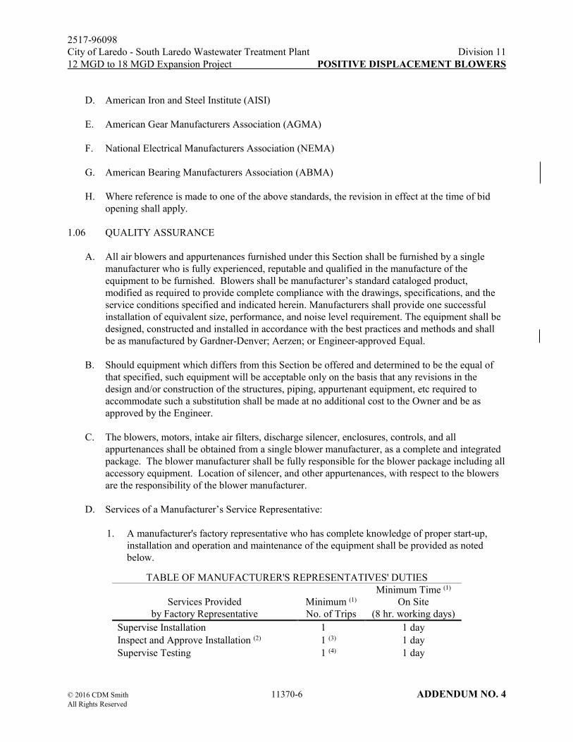
2517-96098
City of Laredo - South Laredo Wastewater Treatment Plant Division 11
12 MGD to 18 MGD Expansion Project POSITIVE DISPLACEMENT BLOWERS
© 2016 CDM Smith 11370-6 ADDENDUM NO. 4 All Rights Reserved
D. American Iron and Steel Institute (AISI)
E. American Gear Manufacturers Association (AGMA)
F. National Electrical Manufacturers Association (NEMA)
G. American Bearing Manufacturers Association (ABMA)
H. Where reference is made to one of the above standards, the revision in effect at the time of bid
opening shall apply.
1.06 QUALITY ASSURANCE
A. All air blowers and appurtenances furnished under this Section shall be furnished by a single
manufacturer who is fully experienced, reputable and qualified in the manufacture of the
equipment to be furnished. Blowers shall be manufacturer’s standard cataloged product,
modified as required to provide complete compliance with the drawings, specifications, and the
service conditions specified and indicated herein. Manufacturers shall provide one successful
installation of equivalent size, performance, and noise level requirement. The equipment shall be
designed, constructed and installed in accordance with the best practices and methods and shall
be as manufactured by Gardner-Denver; Aerzen; or Engineer-approved Equal.
B. Should equipment which differs from this Section be offered and determined to be the equal of
that specified, such equipment will be acceptable only on the basis that any revisions in the
design and/or construction of the structures, piping, appurtenant equipment, etc required to
accommodate such a substitution shall be made at no additional cost to the Owner and be as
approved by the Engineer.
C. The blowers, motors, intake air filters, discharge silencer, enclosures, controls, and all
appurtenances shall be obtained from a single blower manufacturer, as a complete and integrated
package. The blower manufacturer shall be fully responsible for the blower package including all
accessory equipment. Location of silencer, and other appurtenances, with respect to the blowers
are the responsibility of the blower manufacturer.
D. Services of a Manufacturer’s Service Representative:
1. A manufacturer's factory representative who has complete knowledge of proper start-up,
installation and operation and maintenance of the equipment shall be provided as noted
below.
TABLE OF MANUFACTURER'S REPRESENTATIVES' DUTIES
Services Provided
by Factory Representative
Minimum (1)
No. of Trips
Minimum Time (1)
On Site
(8 hr. working days)
Supervise Installation 1 1 day
Inspect and Approve Installation (2) 1 (3) 1 day
Supervise Testing 1 (4) 1 day

2517-96098
City of Laredo - South Laredo Wastewater Treatment Plant Division 11
12 MGD to 18 MGD Expansion Project POSITIVE DISPLACEMENT BLOWERS
© 2016 CDM Smith 11370-7 ADDENDUM NO. 4 All Rights Reserved
TABLE OF MANUFACTURER'S REPRESENTATIVES' DUTIES
Services Provided
by Factory Representative
Minimum (1)
No. of Trips
Minimum Time (1)
On Site
(8 hr. working days)
Instruct Owner's and Engineer's
Representatives in proper start-up and
operations and maintenance
1 (5) 1 day
(1) The manufacturer's factory representative shall be present at frequent enough
intervals to ensure proper installation, testing and initial operation of the
equipment. (2) The manufacturer's representative shall provide to the Engineer a written
certification that the system has been installed in accordance with the
manufacturer's recommendations. (3) May be done directly following completion of Item 1 if acceptable to the
Engineer. (4) May be done directly following completion of Item 2 if acceptable to
the Engineer. (5) This instruction may be given following completion of Item 3, provided that the
test is successful and the operation and maintenance manuals have been
approved.
2. The Contractor shall be responsible for requesting and coordinating these services, including
coordination with all affected trades. The Contractor shall also be responsible for
documenting the delivery of all manufacturer/vendor on-site services.
1.07 SYSTEM DESCRIPTION
A. Each blower shall include, but not be limited to, the following items to be supplied by the blower
manufacturer:
1. Rotary positive displacement blower (driven by an electric motor through V-belt drives).
2. Air intake filter.
3. Discharge silencer.
4. Manual butterfly valve.
5. Flexible pipe connectors.
6. Pressure relief valve.
7. Pressure gauge or PLC read out.
8. Check valve.
9. Discharge high temperature switch and discharge temperature gauge reading through
vendor-supplied PLC is acceptable.

2517-96098
City of Laredo - South Laredo Wastewater Treatment Plant Division 11
12 MGD to 18 MGD Expansion Project POSITIVE DISPLACEMENT BLOWERS
© 2016 CDM Smith 11370-8 ADDENDUM NO. 4 All Rights Reserved
10. Flexible expansion joints.
11. Vibration isolator pad.
12. Other appurtenances as required by the blower manufacturer.
B. For this project, the blower assemblies shall be capable of supplying air on a continuous basis at
rated capacity for mixing primary, waste activated sludge and thickened sludge and aerating
treated wastewater.
C. Design Requirements
CCB-BLR-03, Positive Displacement Blower - Chlorine Contact Basins
1. Blower Location: Outdoors, in ventilated blower enclosure
2. Gas: Air
3. Blower Capacity: 585 SCFM
4. Discharge Pressure: 6.4 psig
5. Inlet Pressure: 14.5 psia
6. Inlet Temperature: 20°F - 110°F (design is 110°F)
7. Motor: 30 HP, 1800 RPM, 3/60/460V TEFC
8. Drive: V-Belt & OSHA guard
9. Controls: Hand/Off/Auto selector switch and start/stop pushbuttons (local
mode only) mounted on blowers control panel
10. Alarms/Shutdowns: High temperature, motor overload, high motor winding
temperature, phase failure
AB-OABLR-01, Stand-by Positive Displacement Blower – Aeration Basins (for Odorous Air
Diffusion)
1. Blower Location: Blower Building, open-aired canopy;
Unit to be installed by the City
2. Gas: Odorous Air, containing 10 ppm H2S (from Headworks)
3. Blower Capacity: 2,870 SCFM
4. Discharge Pressure: 10.0 psig (design)

2517-96098
City of Laredo - South Laredo Wastewater Treatment Plant Division 11
12 MGD to 18 MGD Expansion Project POSITIVE DISPLACEMENT BLOWERS
© 2016 CDM Smith 11370-9 ADDENDUM NO. 4 All Rights Reserved
5. Inlet Pressure: 14.5 psia
6. Inlet Temperature: 20°F - 110°F (design is 110°F)
7. Motor: 200 HP, 1800 RPM, 3/60/460V TEFC
8. Drive: V-Belt & OSHA guard
9. Controls: Re-use existing Local Control Panel.
Refer to P-4 of attached Design Documents.
10. Alarms/Shutdowns: High temperature, overload, high motor winding temperature,
phase failure
D. At all levels of performance of each blower, the noise level shall comply with the latest OSHA
noise exposure requirements for eight (8) hours exposure.
E. The manufacturer shall factor all inlet and discharge pressure losses into the performance
calculations.
1.08 DELIVERY, STORAGE, AND HANDLING
C. Delivery storage and handling shall be in accordance with Section 01170. All parts shall be
properly protected so that no damage or deterioration will occur during a prolonged delay from
the time of shipment until installation is completed and the unit and equipment are ready for
operation.
1.09 MAINTENANCE
A. Tools and Spare Parts
1. Furnish one set of all special tools required for the proper servicing of all equipment
supplied under this Section packed in a suitable steel tool chest with a lock.
2. Furnish all spare parts recommended by the manufacturer for one year's normal operation
and maintenance of the equipment. These shall include at a minimum the following:
a. Two (2) sets of intake filter elements.
b. Two (2) sets of complete repair kits with gaskets, O-ring & bearings.
c. Two (2) complete sets of drive V-belts.
d. Four (4) Quarts of Lubricant
3. All spare parts shall be suitably packaged or boxed for long term storage. Each part shall be
clearly identified by part description, part number and all other pertinent data.

2517-96098
City of Laredo - South Laredo Wastewater Treatment Plant Division 11
12 MGD to 18 MGD Expansion Project POSITIVE DISPLACEMENT BLOWERS
© 2016 CDM Smith 11370-10 ADDENDUM NO. 4 All Rights Reserved
1.10 WARRANTY
A. The equipment manufacturer shall provide a two (2) year guarantee for all parts associated with
the equipment defined by this Specification and the labor associated with repair and/or
replacement of the parts. The guarantee must be submitted during the shop drawing phase.
Approval of the shop drawings will be contingent on the receipt of the guarantee. If any part of
the equipment should fail during the warranty period, it will be replaced at no expense to the
Owner. The manufacturer's warranty period shall commence at the time of substantial
completion of related work.
PART 2 PRODUCTS
2.01 MATERIALS AND EQUIPMENT
A. All equipment shall be designed and proportioned to have liberal strength, stability and stiffness
and shall be especially adapted for the intended service. Ample room and facilities shall be
provided for inspection, repairs and adjustments. Sound enclosures shall not interfere with this
requirement and shall not require disassembly of the piping or use of tools to meet the
aforementioned requirements. Operator shall not be required to reach over any component of the
blower package to perform oil filling or draining.
B. Blower bases. No special foundations shall be required. Blowers and ancillary equipment shall be
installed on a concrete slab without grouting. Vibration isolating feet and flexible pipe connectors
with a minimum efficiency of 80 percent shall be used. When required, special mounts shall be
provided for the specified seismic zone and it is the responsibility of the vendor to provide the
corresponding calculations supporting the selection of the mounts. Blower Manufacturer shall
supply anchor bolt sizing and templates for bolt installation.
C. Blowers shall each be furnished as part of an equipment package which includes outside pipe
inlet covers, the inlet filter, inlet and outlet silencers, base frame, motor, check valve, pressure
relief valves, start unloading valves, instrumentation, inlet and discharge flex connectors, sound
enclosures, steel skid, and other accessory equipment named in Paragraph 2.03.
D. Brass or stainless steel nameplates, giving the manufacturer, the serial number of the item, the
rated capacity, speed and other pertinent data shall be properly and rigidly attached to each item
of equipment.
E. This Section is intended to give a general description of what is required, but does not cover all
details which may vary in accordance with the exact requirements of the equipment as offered. It
is, however, intended to cover the furnishing, delivery, installation and field-testing of all
materials, equipment and apparatus as required. Any additional auxiliary equipment necessary
for the proper operation of the proposed installation not mentioned in this Section shall be
furnished by the supplier / manufacturer and installed by the Contractor. General configuration of
the blower package, including piping orientation is based on a vertical air flow direction through
the blower stage. Any modifications to accommodate a different blower arrangement, associated
piping and appurtenances shall be the supplier / manufacturer’s responsibility to coordinate and
redesign and shall be done at no additional cost to the Owner.

2517-96098
City of Laredo - South Laredo Wastewater Treatment Plant Division 11
12 MGD to 18 MGD Expansion Project POSITIVE DISPLACEMENT BLOWERS
© 2016 CDM Smith 11370-11 ADDENDUM NO. 4 All Rights Reserved
F. The blowers, motors, silencers and accessories shall be designed to insure the sound pressure
level as installed with one unit running does not exceed 85 dBA at a distance of 3-ft from the
outline of the blower package in a free field test. When tested in accordance with ISO 2151, the
equipment shall be tested in an arrangement similar to the equipment to be furnished herein. The
test shall include the noise from the motor. Factory test results shall be submitted to the Engineer.
G. Performance tests after installation shall be performed to confirm installed sound pressure level is
below maximum allowable. It is the blower manufacturer’s responsibility under this Section, at
no additional cost to the Owner, to provide whatever measures required to meet the specified
noise criteria. Acoustic treatment must be installed by qualified personnel trained to avoid
transmission of structure-borne noise from the pipe and silencers to the insulation shell. All
measures so provided must be approved by the Engineer. Convention sound level meter shall be
required to verify noise level.
2.02 BLOWER AND MOTOR
A. The blower shall deliver oil-free air. The blower and motor shall be mounted on a common
fabricated steel base designed for ease of changing sheaves and V-belts. The unit shall be
designed in such a manner that the compressor housing is sound insulated without impairing the
operation of the unit.
B. The blower shall be a positive displacement rotary blower which employs two (2) impellers to
pressurize a trapped volume of air at a controlled rate prior to exposing it to a discharge pressure.
C. Lubrication shall be provided by a splash lubrication system for gears and bearings.
D. The blower shall be V-belt driven by an electric motor mounted on a common base. V-belt
drives shall be Dodge Sealed-Life II V-belts with matching taper lock sheaves and taper lock
bushings.
E. The blower casing shall be of one piece construction with separate headplates and shall be made
of close-grained cast iron suitably ribbed to prevent distortion under the specified operating
conditions.
F. The impellers shall be ductile iron, shall be the straight, or three (3) helocal lobe involute type
and shall operate without rubbing, liquid seals or lubrication. The impellers shall be positively
timed by a pair of accurately machined heat-treated alloy steel helical timing gears. The shafts
shall be alloy steel forgings and shall be flanged and attached to each end of each impeller by
high tensile strength cap screws. Each impeller and shaft assembly shall be supported by
double-row spherical roller bearings sized for a minimum 80,000 hours B-10 life.
G. Timing gears and all bearings shall be oil splash lubricated. Bearings and gears shall not be
grease lubricated. Recessed oil sight glasses shall be directly attached on each oil sump to
observe the oil level in the reservoirs. A double sealing arrangement shall be provided to prevent
lubricant from contaminating the air stream. The sealing arrangement may not utilize any type of
lip seal. Seals shall be designed to prevent lubricant from leaking into the air stream and from
leaking from the machine. The stand-by odorous blower unit shall be designed and sealed to

2517-96098
City of Laredo - South Laredo Wastewater Treatment Plant Division 11
12 MGD to 18 MGD Expansion Project POSITIVE DISPLACEMENT BLOWERS
© 2016 CDM Smith 11370-12 ADDENDUM NO. 4 All Rights Reserved
allow no leakage of H2S gas from the blower seals. Four rotary piston ring shaft seals, an oil
slinger, and an o-ring seal shall be provided at the point where the shaft passes through the side
plate. Further provision shall be made to vent the impeller side of the oil seal to atmosphere to
eliminate any possible carry-over of lubricant into the air stream. Oil drain valves shall be
directly mounted on the oil sump covers. The blower stage shall be removable from its base
without having to drain the oil. An oil fill and drain kit shall be provided.
H. The motor shall be a horizontal, totally enclosed fan-cooled, induction motor rated for 460VAC,
and constant speed. The motor horsepower and speed shall be as specified in Paragraph 1.07.C.
The motors shall be inverter duty rated.
I. For the stand-by odorous air blower (AB-OABLR-01), all components that will come into
contact with the air stream shall be coated with two coats of highly corrosion resistant
fluoropolymer. Blower manufacturer shall have documented experience applying the corrosion
coating on the internals of positive displacement blowers. The fluorpolymer shall maintain proper
function up to a temperature of 500 degrees F and shall be Teflon®, CorrgardTM, or approved
equal. Blower manufacturer shall provide an explanation of the application procedure as part of
the submittal. Manufacturer shall provide any additional protection deemed necessary for
handling the odorous air described in section 1.07.
2.03 ACCESSORIES
A. Each blower shall be provided with the following accessory equipment: one inlet filter, one inlet
silencer (or combination filter silencer), one discharge silencer, one pair of flexible connectors,
one check valve, one pressure relief valve, one automatic unloading valve sized by the blower
manufacturer, inlet pressure gauge, discharge pressure gauge, one discharge temperature
gauge/switch as shown on the Drawings. All accessories shall be suitable for use at the elevated
temperatures, pressures and other conditions of the blowers discharge flow.
B. The inlet filter/silencer shall be mounted above the blower and shall be enclosed in a fabricated
air inlet box with maintenance access door. The filter shall be accessible for easy service. The
filters shall be dry washable type with synthetic media between metal grids. The inlet
filter/silencer housing for the odorous air blower shall be of heavy duty, all welded Type 304
stainless steel construction.
C. The discharge silencer shall be an integral part of the blower base and be of all welded steel
construction. Silencer shall be properly sized for the design conditions, shall be specifically
designed for use with positive displacement blowers and shall be for mounting. The silencers for
odorous air blower shall be of heavy duty, all welded Type 304 stainless steel construction with a
working pressure of at least 15 psig.
D. Flexible pipe connectors shall be high temperature rubber sleeve type with flanged ends equal to
Super-Flex MFNC with EPDM cover and liner by Mason Industries, Inc. or equal.
E. A pressure gauge calibrated 0 to 15 psig shall be provided on the discharge side of the blower.
Gauge shall be equal to Ashcroft 1008, stainless steel case, glycerin filled, with 4-1/2-in dial face.
A suitable tee handled corporation stop or ball valve shall be installed between each gauge and
the connection to the air piping. Discharge temperature and pressure reading though vendor-

2517-96098
City of Laredo - South Laredo Wastewater Treatment Plant Division 11
12 MGD to 18 MGD Expansion Project POSITIVE DISPLACEMENT BLOWERS
© 2016 CDM Smith 11370-13 ADDENDUM NO. 4 All Rights Reserved
supplied PLC is acceptable.
F. Pressure relief valves shall be of the spring-loaded type. Size shall be as recommended by the
blower manufacturer. Each blower shall be supplied with a single relief valve that has the
capacity of relieving the entire discharge flow of the blower. Set pressure shall be 2 lb greater
than the maximum discharge pressure rating. The relief valve shall be housed within the sound
enclosure and shall relieve into a segmented section of the enclosure. The design of the valve
shall permit the discharge of the relief valve to be piped away. The pressure relief valves for the
odorous air blower shall be stainless steel valve.
G. Safety devices and controls as recommended by the blower manufacturer shall be provided
including an OSHA approved hot dipped galvanized guard for the V-belt drive.
H. Refer to Section 15100 for Check Valve specifications.
I. Vibration isolation pads shall be provided. Pads shall be molded synthetic rubber and cork sized
to fit the structural steel base. Pads shall be as manufactured by Korfund or approved equal.
J. A high discharge air temperature switch with operating range of 150° to 260°F shall be mounted
in the discharge piping of each blower. Sensor shall be a capillary type with a remote brass bulb.
K. Two (2) circum aural Hearing Protection Devices M.S.A. Noisefoe Mark IV Ear Muffs or equal
shall be furnished for the protection of operating personnel. The equipment shall be supplied
with a high-impact plastic window type cabinet, suitable for wall mounting.
L. Unloading valves shall be required for motor larger than for 200 HP and greater blowers shall be
butterfly automatically actuated by blower discharge pressure. The valve shall be provided as part
of the blower package to allow starting the motor or switching the windings under reduced load.
The unloading relief valve shall be housed within the sound enclosure and shall relieve into a
segmented section of the enclosure.
2.04 BLOWER ENCLOSURES
A. Blowers shall be housed in individual acoustical enclosures. The enclosures shall be designed for
noise reduction (per Paragraph 2.01.F) and the outside shall be galvanized steel with epoxy or
powder coating paint or aluminum.
A. The enclosures shall be mechanically vented to assure proper cooling of the blowers. Vent fans
shall have a maximum 1.5 horsepower motor.
B. Enclosure shall be constructed to easily accommodate service and maintenance functions. The
enclosure shall have a minimum of three removable wall access doors appropriately placed for
viewing and maintenance purposes.
C. Enclosure shall include a removable roof panel to permit removal of blower and / or motor
without removal of the enclosure.

2517-96098
City of Laredo - South Laredo Wastewater Treatment Plant Division 11
12 MGD to 18 MGD Expansion Project POSITIVE DISPLACEMENT BLOWERS
© 2016 CDM Smith 11370-14 ADDENDUM NO. 4 All Rights Reserved
2.05 CONTROL PANEL
A. The equipment manufacturer shall be responsible for sizing the NEMA 4X control panel and the
control panel shall conform to the requirements of Section 01179. Blower suppliers shall refer to
Drawings for signals between blower control panel and plant SCADA system.
B. The pre-wired control panel shall house all control components and the combination motor
starters for motors less than 50 HP. Reduced voltage starters shall be used for all motors greater
than 50 HP. The control panel shall contain run, stop and power on indicator lights, H/O/A
selector switch, standard start and stop pushbuttons, emergency shut-off pushbutton, phase failure
relay, timing relay to stagger motor starting sequences, and all miscellaneous appurtenances
required for a complete and fully operational system.
C. Placing the blower H-O-A switch in HAND mode shall allow manual start and stop of the blower
from the local control panel only.
D. The blower shall be initiated to start when the H-O-A switch is placed in AUTO. The blower will
only shut-down upon power loss and by conditions described in Paragraph 1.07.C. In the event
of a power loss and subsequent recovery of power, the blower will automatically restart when in
AUTO mode.
E. In lieu of the analog gauges and H-O-A switch, Manufacture can provide a panel mounted PLC
controller in a NEMA 4 enclosure. The PLC Controller shall start-stop the unit, read discharge
air pressure, discharge temperature, inlet filter differential, run hours, service interval, service
advisories, shut downs for high discharge temperature, high enclosure temperature, high inlet
filter differential. The PLC controller shall also provide blower sequencing and SCADA
communications.
2.06 HARDWIRED INPUT/OUTPUT INTERFACE
A. The following hardwired discrete input signals shall be available for remote monitoring from
Plant SCADA system:
1. Blower Failed Alarm
2. Blower Running Status
3. Blower Local/Remote Status
4. Blower Overload Alarm
5. Blower High Motor Winding Alarm
6. Blower High Discharge Temperature

2517-96098
City of Laredo - South Laredo Wastewater Treatment Plant Division 11
12 MGD to 18 MGD Expansion Project POSITIVE DISPLACEMENT BLOWERS
© 2016 CDM Smith 11370-15 ADDENDUM NO. 4 All Rights Reserved
B. The following hardwired discrete output signals shall be accepted for remote control from Plant
SCADA system:
1. Blower Start
2. Blower Stop
2.07 SURFACE PREPARATION AND SHOP PAINTING
A. All surfaces shall be prepared and shop primed as part of the work of this Section (for those items
not furnished with factory finish enamel paint). Surface preparation and shop painting shall be as
specified in Section 09901.
B. Field painting shall be as specified in Section 09902.
PART 3 EXECUTION
3.01 FACTORY TEST
A. Each of the blowers and appurtenances, including baseplate and silencers, shall be assembled at
the manufacturer’s production facility and tested by the blower manufacturer. Tests shall include
a performance test under full load conditions and at the performance conditions specified.
Performance test shall measure flow, pressure, horsepower, vibration, and noise level at the
design point. A performance test report shall be provided. The test method shall be per an
internationally recognized standard such as ISO or DIN. Equipment will have been run for ample
time to allow for thermal adjustment before data can be taken. Test shall include ambient
conditions, flow, bhp, slip, inlet and outlet temperature and motor efficiency. Certified letter for
acoustical test results demonstrating blowers operate at an acceptable noise level as specified
herein.
B. Certified report of dynamic balancing and maximum vibration amplitude.
1. Conduct dynamic balancing of complete rotating assembly prior to blower assembly.
2. Impeller balancing shall be conducted in accordance with ISO 1940 G 2.5. The double
amplitude of vibration in every plane measured on the blower bearing housing adjacent and
relative to each radial bearing shall not exceed 1.25 mils.
C. Performance Tests:
1. Perform slip tests at the factory using the same tolerances and clearances between
aerodynamic surfaces as recommended for actual continuous field operation. A written
statement of compliance to this requirement shall be included as a part of this certified test
report.
2. After successful completion of the certified performance test, submit test results for each
blower.

2517-96098
City of Laredo - South Laredo Wastewater Treatment Plant Division 11
12 MGD to 18 MGD Expansion Project POSITIVE DISPLACEMENT BLOWERS
© 2016 CDM Smith 11370-16 ADDENDUM NO. 4 All Rights Reserved
D. Factory Acceptance Testing of both the Local Blower and Main Control Panels and shall include:
Factory As-built control panel electrical schematics, interconnection wiring diagram, bill of
materials, calibration reports, calibration reports, and a signed functional description of the
blower system.
3.02 INSTALLATION
A. Installation of the blowers and appurtenances shall be in strict accordance with the manufacturer's
recommendations and instructions in the locations as shown on the Drawing. Installation shall
include the furnishing of the required oil and grease for initial operation. The grades of oil and
grease shall be in accordance with the manufacturer's recommendations. Anchor bolts shall be set
in accordance with approved shop drawings.
B. The services of a factory representative shall be furnished to check over the complete air system
installation to the satisfaction of the Engineer.
C. Installation shall include the furnishing and installation of all supports and bracing as may be
required to support the blowers, silencers and piping and to prevent any excessive or harmful
vibration or movement of the equipment or piping resulting from the operation of the system.
D. The services of a factory representative shall be furnished for one eight-hour days to check over
the blower installation to the satisfaction of the Engineer and Owner. The factory representative
shall provide to the Engineer a written certification that the system has been installed in
accordance with the manufacturer’s recommendations.
3.03 INSTALLATION, INSPECTION AND FIELD TEST
A. After installation of all equipment has been completed and as soon as conditions permit, conduct
an acceptance test under actual operating conditions to determine the operation is satisfactory and
free from excessive vibration. The test shall consist of a minimum of 4 hours operation of each
blower with readings taken and recorded at 30-minute intervals. The blower manufacturer's field
service representative shall be present during the field test. The field test shall demonstrate the
operation of each blower over its specified operating range. The manufacturer shall take and
record the following readings during such testing to demonstrate conformance with the
specification.
1. Inlet pressure, psia
2. Inlet temperature, oF
3. Discharge pressure, psia
4. Discharge temperature, oF
5. Capacity, scfm
6. Speed, rpm

2517-96098
City of Laredo - South Laredo Wastewater Treatment Plant Division 11
12 MGD to 18 MGD Expansion Project POSITIVE DISPLACEMENT BLOWERS
© 2016 CDM Smith 11370-17 ADDENDUM NO. 4 All Rights Reserved
7. Horsepower, Hp
8. Noise level, dBA
9. Vibration level of motor and blower
B. Furnish all power, facilities, labor, supplies, test devices and field instruments required to conduct
field tests. All alarm and shutdown devices shall be tested and calibrated during the field test.
Submit the field test report.
C. Noise and vibration tests shall be conducted to ensure that the equipment noise level conforms to
this Section and does not exceed 85 dBA free field when measured one meter from the equipment
being tested, and there is no harmful vibration in the blower units or in the system piping. Each
blower package shall be tested, with one unit running, in accordance with ISO 2151.
C. Correct or replace all defects or defective equipment revealed or noted during the field tests, at no
additional cost to the Owner, and repeat tests until specified results and results acceptable to the
Engineer are obtained. The Contractor is to provide all labor, piping, equipment, test gauges,
vibration testing equipment and materials for conducting tests.
C. Equipment that is unable to meet all the requirements specified to the satisfaction of the Engineer
shall be removed and replaced with equipment that complies with all the requirements at no
additional cost to the Owner.
END OF SECTION

THIS PAGE INTENTIONALLY LEFT BLANK

2517-96098 Division 13
City of Laredo - South Laredo Wastewater Treatment Plant I&C - APPLICATIONS
12 MGD to 18 MGD Expansion Project ENGINEERING SERVICES
© 2016 CDM Smith Inc. 13306-9 ADDENDUM NO. 4 All Rights Reserved
1.11 SUPPORT CONTRACT
A. Refer to Section 13300 Paragraph 1.01.
1.12 NOMENCLATURE AND IDENTIFICATION
A. Refer to Section 13300.
1.13 COORDINATION MEETINGS AND WORKSHOPS
A. Refer to Section 13300. The meetings listed in this section relate to software development and are
in addition to the coordination meetings identified in 13300. Schedule and conduct a mandatory
coordination meeting/workshop as specified herein. The meeting shall be held at the Owner’s
designated location or by telephone (where noted) and shall include attendance by the Owner, the
Engineer, the Contractor, relevant Vendors and the PCSS's Project Engineer. The PCSS shall
prepare and distribute an agenda for the coordination meetings a minimum of one week before
the scheduled meeting date. The PCSS shall prepare and distribute meeting minutes to all
attendees within one week following the meeting.
B. A Graphics Development and Review Meeting combined with Historical Data Management and
Reports Workshop shall be held at the Owner’s designated location to begin the process of
building the required HMI system. At this meeting, the PCSS will present templates, samples
from other projects, an initial screen list, and samples of system navigation tools, proposed
tags/labels on graphics to the Owner for consideration. The PCSS shall solicit Engineer/Owner
input for storage and management of historical data and format of daily, monthly and yearly
reports. The PCSS shall bring a working system to allow for a live demonstration of the various
software tools. This meeting will last up to one business day.
C. In addition to the general conference call per Specification Section 13300, Paragraph 1.04, the
PCSS shall schedule and administer individual coordination conference calls with Vendors for
graphics development, data mapping, testing, and startup for all the Vendor supplied systems in
the project. There is no need for the Owner or Engineer to participate in these individual
coordination phone calls. The PCSS shall identify those Vendors that are not providing timely
coordination information to the General Contractor.
1.14 ADDITIONAL PROGRAMMING AND ONSITE SUPPORT ALLOWANCES
A. Provide up to 120 hours of SCADA system including PLC, HMI, or TSOIT programming, testing
support, or coordination efforts in addition to the required programming efforts identified in the
specification. The intent of this support is that it would be utilized between startup and 1 year
after substantial completion to provide for customization or minor modifications to the system. It
is not intended to substitute for warranty repairs of software or other items.
B. Provide travel and per diem expenses for up to 10 days for a competent I&C
technician/programmer to be at the plant site to implement the programming changes under this
allowance.
C. Note the hours and site days in the schedule of values, and update the schedule as they are used.
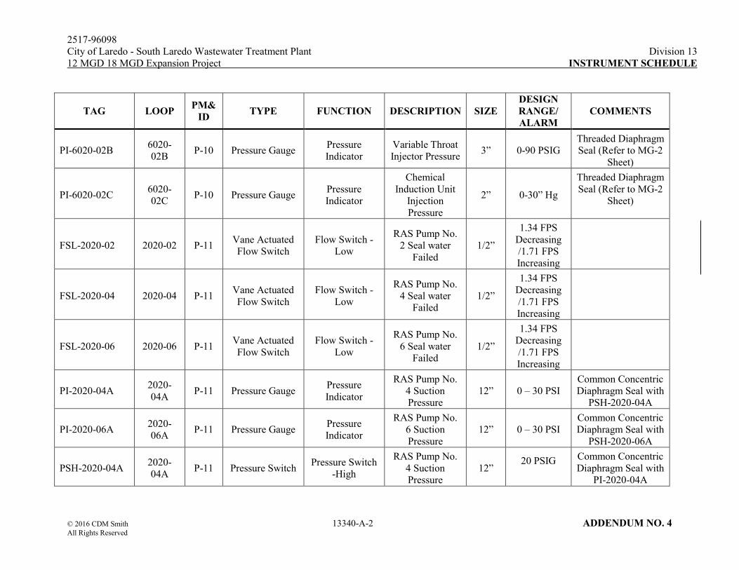
2517-96098
City of Laredo - South Laredo Wastewater Treatment Plant Division 13
12 MGD 18 MGD Expansion Project INSTRUMENT SCHEDULE
© 2016 CDM Smith 13340-A-2 ADDENDUM NO. 4 All Rights Reserved
TAG LOOP PM&
ID TYPE FUNCTION DESCRIPTION SIZE
DESIGN
RANGE/
ALARM
COMMENTS
PI-6020-02B 6020-
02B P-10 Pressure Gauge
Pressure
Indicator
Variable Throat
Injector Pressure 3” 0-90 PSIG
Threaded Diaphragm
Seal (Refer to MG-2
Sheet)
PI-6020-02C 6020-
02C P-10 Pressure Gauge
Pressure
Indicator
Chemical
Induction Unit
Injection
Pressure
2” 0-30” Hg
Threaded Diaphragm
Seal (Refer to MG-2
Sheet)
FSL-2020-02 2020-02 P-11 Vane Actuated
Flow Switch
Flow Switch -
Low
RAS Pump No.
2 Seal water
Failed
1/2”
1.34 FPS
Decreasing
/1.71 FPS
Increasing
FSL-2020-04 2020-04 P-11 Vane Actuated
Flow Switch
Flow Switch -
Low
RAS Pump No.
4 Seal water
Failed
1/2”
1.34 FPS
Decreasing
/1.71 FPS
Increasing
FSL-2020-06 2020-06 P-11 Vane Actuated
Flow Switch
Flow Switch -
Low
RAS Pump No.
6 Seal water
Failed
1/2”
1.34 FPS
Decreasing
/1.71 FPS
Increasing
PI-2020-04A 2020-
04A P-11 Pressure Gauge
Pressure
Indicator
RAS Pump No.
4 Suction
Pressure
12” 0 – 30 PSI
Common Concentric
Diaphragm Seal with
PSH-2020-04A
PI-2020-06A 2020-
06A P-11 Pressure Gauge
Pressure
Indicator
RAS Pump No.
6 Suction
Pressure
12” 0 – 30 PSI
Common Concentric
Diaphragm Seal with
PSH-2020-06A
PSH-2020-04A 2020-
04A P-11 Pressure Switch
Pressure Switch
-High
RAS Pump No.
4 Suction
Pressure
12” 20 PSIG
Common Concentric
Diaphragm Seal with
PI-2020-04A

2517-96098
City of Laredo - South Laredo Wastewater Treatment Plant Division 13
12 MGD 18 MGD Expansion Project INSTRUMENT SCHEDULE
© 2016 CDM Smith 13340-A-3 ADDENDUM NO. 4 All Rights Reserved
TAG LOOP PM&
ID TYPE FUNCTION DESCRIPTION SIZE
DESIGN
RANGE/
ALARM
COMMENTS
PSH-2020-06A 2020-
06A P-11 Pressure Switch
Pressure Switch
-High
RAS Pump No.
6 Suction
Pressure
12” 20 PSIG
Common Concentric
Diaphragm Seal with
PI-2020-06A
PI-2020-02 2020-02 P-11 Pressure Gauge Pressure
Indicator
RAS Pump No.
2 Plant Water
Pressure
1/2” 0 – 30 PSI
PI-2020-04 2020-04 P-11 Pressure Gauge Pressure
Indicator
RAS Pump No.
4 Plant Water
Pressure
1/2” 0 – 30 PSI
PI-2020-06 2020-06 P-11 Pressure Gauge Pressure
Indicator
RAS Pump No.
6 Plant Water
Pressure
1/2” 0 – 30 PSI
PI-2020-04B 2020-
04B P-11 Pressure Gauge
Pressure
Indicator
RAS Pump No.
4 Discharge
Pressure
14” 0 – 30 PSI
Common Concentric
Diaphragm Seal with
PSH-2020-04B
PI-2020-06B 2020-
06B P-11 Pressure Gauge
Pressure
Indicator
RAS Pump No.
6 Discharge
Pressure
14” 0 – 30 PSI
Common Concentric
Diaphragm Seal with
PSH-2020-06B
PSH-2020-04B 2020-
04B P-11 Pressure Switch
Pressure Switch
-High
RAS Pump No.
4 Discharge
Pressure
14” 20 PSIG
Common Concentric
Diaphragm Seal with
PI-2020-04B
PSH-2020-06B 2020-
06B P-11 Pressure Switch
Pressure Switch
-High
RAS Pump No.
6 Discharge
Pressure
14” 20 PSIG
Common Concentric
Diaphragm Seal with
PI-2020-06B
FE/FIT-2045 2045 P-11 Magnetic Flow
Meter
Flow
Element/Indicati
ng Transmitter
RAS Flow 24" 0-10,000
GPM
Remote mount flow
transmitter. Provide
sunshield and surge
protector for the
transmitter. Provide

2517-96098
City of Laredo - South Laredo Wastewater Treatment Plant Division 13
12 MGD 18 MGD Expansion Project INSTRUMENT SCHEDULE
© 2016 CDM Smith 13340-A-4 ADDENDUM NO. 4 All Rights Reserved
TAG LOOP PM&
ID TYPE FUNCTION DESCRIPTION SIZE
DESIGN
RANGE/
ALARM
COMMENTS
Hard Rubber liner
for flow element.
FSL-2020-01 2020-01 P-12 Vane Actuated
Flow Switch
Flow Switch -
Low
RAS Pump No.
1 Seal water
Failed
1/2”
1.34 FPS
Decreasing
/1.71 FPS
Increasing
FSL-2020-03 2020-03 P-12 Vane Actuated
Flow Switch
Flow Switch -
Low
RAS Pump No.
3 Seal water
Failed
1/2”
1.34 FPS
Decreasing
/1.71 FPS
Increasing
FSL-2020-05 2020-05 P-12 Vane Actuated
Flow Switch
Flow Switch -
Low
RAS Pump No.
5 Seal water
Failed
1/2”
1.34 FPS
Decreasing
/1.71 FPS
Increasing
PI-2020-01 2020-01 P-12 Pressure Gauge Pressure
Indicator
RAS Pump No.
1 Plant Water
Pressure
1/2” 0 – 30 PSI
PI-2020-03 2020-03 P-12 Pressure Gauge Pressure
Indicator
RAS Pump No.
3 Plant Water
Pressure
1/2” 0 – 30 PSI
PI-2020-05 2020-05 P-12 Pressure Gauge Pressure
Indicator
RAS Pump No.
5 Plant Water
Pressure
1/2” 0 – 30 PSI
PI-2020-05A 2020-
05A P-12 Pressure Gauge
Pressure
Indicator
RAS Pump No.
5 Suction
Pressure
12” 0 – 30 PSI
Common Concentric
Diaphragm Seal with
PSH-2020-05A

2517-96098
City of Laredo - South Laredo Wastewater Treatment Plant Division 13
12 MGD 18 MGD Expansion Project INSTRUMENT SCHEDULE
© 2016 CDM Smith 13340-A-5 ADDENDUM NO. 4 All Rights Reserved
TAG LOOP PM&
ID TYPE FUNCTION DESCRIPTION SIZE
DESIGN
RANGE/
ALARM
COMMENTS
PSH-2020-05A 2020-
05A P-12 Pressure Switch
Pressure Switch
-High
RAS Pump No.
5 Suction
Pressure
12” 20 PSIG
Common Concentric
Diaphragm Seal with
PI-2020-05A
PI-2020-05B 2020-
05B P-12 Pressure Gauge
Pressure
Indicator
RAS Pump No.
5 Discharge
Pressure
14” 0 – 30 PSI
Common Concentric
Diaphragm Seal with
PSH-2020-05B
PSH-2020-05B 2020-
05B P-12 Pressure Switch
Pressure Switch
-High
RAS Pump No.
5 Discharge
Pressure
14” 20 PSIG
Common Concentric
Diaphragm Seal with
PI-2020-05B

R
IO
G
R
A
N
D
E
R
IV
E
R
SS
SSSS
CITY OF LAREDO, TEXAS
SOUTH LAREDO WASTEWATER TREATMENT PLANT
12 MGD TO 18 MGD EXPANSION PROJECT
1777 N.E. Loop 410, Suite 500
San Antonio, Texas 78217
Tel: (512) 826-3200
© 2
01
3
TBPE Firm Registration No. F-3043
8204 Westglen Drive
Houston,, Texas 77063
Tel: (713) 868-6900
TBPE Firm Registration No. F-4066
8204 Westglen Drive
Houston,, Texas 77063
Tel: (713) 868-6900
TBPE Firm Registration No. F-4066
N
”

···
··
·
·
·
··
”
”
”
OH
PL
OH
PL
OH
PL
S
S
S
S
S
S
S
S
S
S
SS
SS
SS
SS
1 1/2'' W
S
S
OH
PL
OH
PL
OH
PL
S
S
S
S
S
S
S
S
S
S
SS
SS
SS
SS
1 1/2'' W
S
S
658
366.87
mh#36
OH
PL
OH
PL
OH
PL
S
S
S
S
S
S
S
S
S
S
SS
SS
SS
SS
1 1/2'' W
S
S
OH
PL
OH
PL
OH
PL
S
S
S
S
S
S
S
S
S
S
SS
SS
SS
SS
1 1/2'' W
S
S
658
366.87
mh#36
CITY OF LAREDO, TEXAS
SOUTH LAREDO WASTEWATER TREATMENT PLANT
12 MGD TO 18 MGD EXPANSION PROJECT
1777 N.E. Loop 410, Suite 500
San Antonio, Texas 78217
Tel: (512) 826-3200
© 2
01
3
TBPE Firm Registration No. F-3043
8204 Westglen Drive
Houston,, Texas 77063
Tel: (713) 868-6900
TBPE Firm Registration No. F-4066
8204 Westglen Drive
Houston,, Texas 77063
Tel: (713) 868-6900
TBPE Firm Registration No. F-4066
N
”

SWPPP
CSN
CITY OF LAREDO, TEXAS
SOUTH LAREDO WASTEWATER TREATMENT PLANT
12 MGD TO 18 MGD EXPANSION PROJECT
1777 N.E. Loop 410, Suite 500
San Antonio, Texas 78217
Tel: (512) 826-3200
© 2013
TBPE Firm Registration No. F-3043
8204 Westglen Drive
Houston,, Texas 77063
Tel: (713) 868-6900
TBPE Firm Registration No. F-4066
8204 Westglen Drive
Houston,, Texas 77063
Tel: (713) 868-6900
TBPE Firm Registration No. F-4066

SZ-9
TYPICAL DETAILS IX
CITY OF LAREDO, TEXAS
SOUTH LAREDO WASTEWATER TREATMENT PLANT
12 MGD TO 18 MGD EXPANSION PROJECT
1777 N.E. Loop 410, Suite 500
San Antonio, Texas 78217
Tel: (210) 826-3200
© 2016
TBPE Firm Registration No. F-3043
ISSUE FOR BID
DETAIL A
SECTION 1 DETAIL B
SECTION 2