augstu 18,2u 0vsotl -...
TRANSCRIPT

Copyright 2010. Refinery Operations
August 18, 2010 Volume:1 Issue :4
1
Refinery OperationsEngineering Solutions, Maintenance, Reliability, Automation and Equipment Relevant to Refinery Processing and Operations
Michel Melin, Colin Baillie and Gordon McElhiney, Grace Davison Refining Technologies, Worms, Germany
Ammonia chloride (NH4Cl) based salt deposition in the FCCU, particularly in the main fractionator continues to be an ongoing problem due to potentially high chloride levels in acidic feeds processed through certain refinery configurations. For example, the increasing volumes of resid processed in higher complex-ity facilities are typically accompanied by higher chloride content. In addi-tion, some refiners are also bypassing the desalter with imported atmospheric residue feedstock, also impacting higher chloride feed levels.
For many of these refiners, extrac-tion of a gasoline side-cut from the main fractionator (MF) for subsequent hydrotreatment to near-zero sulfur lev-els has resulted in main fractionator top
temperatures as low as 100°C (212°F), compared to previous temperatures in the range of 135-145°C (275-293°F). The cooler temperatures have lead to higher salt deposition at the top of the main fractionator. Other likely causes of NH4Cl salt deposition include:
• Poor crude desalter operation• Reprocessing of slops in MF• Leaking overhead condenser
(using sea water)• Overflowing overhead receiver
water boot• Bad distribution of cold reflux
stream (cold spot)• Feedstocks containing organic
chloride from additives used to increase the recovery of oil for cleaning.
In addition to these sources of salt deposition, the Grace Davison Refining Technologies technical service team has
helped various refiners control FCCU salt deposition from other sources, such as chloride-rich slop injected into the main fractionator. This resulted in severe corrosion to main fractionator packing, magnified by the effects of the acidic crudes being processed.
It is important to point out that of all the possible sources of salt deposi-tion, the technical service team from the Grace Davison offices in Worms,
FEATURE: Controlling FCCU Salt Deposition
FeatureControlling FCCU Salt Deposition
reFining technologyFCC Fourth Stage SeparatorsIncreasing Main Fractionator and Debutanizer EfficiencyPredicting FCC YieldsWeighing the benefits of a Grassroots Coker Project or a RevampReducing Heavy Coker Gas Oil Filtration CostsControlling Hydrocracker Runaway Reactions
Processing & oPerations Q&aHeater Thermal Efficiency
automationAvoiding Pump Failures with Advanced Monitoring
Assessing Compressor Train Performance
industry newsValero Reports Profitable 2nd QuarterHigh Activity Coke Selective FCC CatalystAccessing Feed Properties to Predicting FCC YieldsEnhancing Zeolite Technology Used in FCC CatalystsImproved Mass Transfer Equipment Rating ProgramProcessing Highly Acidic Crude Oil
editorial commentsWaiting for More Hydrogen
calendar oF eventscontact us
in this issue
See Feature Page 2 >>
Refinery Operations
2www.RefineryOperations.com
August 18, 2010
Feature Continued
Germany, has shown that there is no possibility of chloride contamination generated from the use of Grace Davi-son’s FCC catalysts, even though chlo-ride is an integral feature of the Grace Davison alumina-sol (Al-sol) binder system. This Al-sol binder system pro-vides the basis for the catalyst’s formu-lation flexibility and the mechanism and careful process by which it has been formulated has been discussed in detail on page 36 of the March 2010 issue of Catalgram®. Briefly, the authors point out that high temperature calcination removes more than 80% of the chloride from the catalyst, and the chloride re-maining on fresh FCC catalyst is very quickly removed in the regenerator be-fore the catalyst makes its first transit to the FCCU’s reactor section.1
As previously noted, NH4Cl deposi-tion primarily occurs at the top of the main fractionator, and is accompanied by an increase in pressure drop. It can also be encountered to a lesser extent in the overhead line, where the gas is passed through the air and water cool-ers, or the downstream FCCU gas plant (Figure 1 page 1). The previously noted pressure drop increase is the main symptom of NH4Cl deposition, other important symptoms include:
• Flooding of MF top section• Plugging of top product draws• Loss of pump duty around heat
exchangers• Loss of separation efficiency
between gasoline and LCO• Higher MF bottom temperature• Increase in reactor/regenerator
pressure• Plugging of reflux/gasoline
pump strainer• Reduced reflux/TPA rate• Wider opening of WGC suction
valve• Difficulty when using HCN for
reboiling depropanizer because the HCN temperature is lower and salt may deposit in the tubes.
Salt deposition can cause a reduction in feed rate as well as a slight product
quality deterioration. This can be a consequence of salt depo-sition itself, but will also temporarily be observed during any resulting period of water wash ap-plied to reduce salt deposition. In ad-dition, corrosion may also be an issue, especially for packed columns. A summary of the consequences of salt deposition include:
• Corrosion of trays/packing• Reduced WGC capacity (lower
suction pressure)• Reduced air blower capacity
(higher regenerator pressure)
• Increased unit delta coke (higher reactor pressure)
• Fouling of slurry circuit (if higher bottoms temperature)
• Poor quality heavy gasoline• Cost associated with reduced
feed rate and off-spec products during periodic water wash
• Lower depropanizer reboiler duty
• Lower debutanizer reboiler duty.
Preventing Ammonia Chloride DepositionWorking with refiners to help solve NH4Cl deposition issues has resulting in recommendations focusing on the main fractionator column’s overhead line and the column’s trays or packing.
To prevent NH4Cl deposition in the overhead line, water is usually added, with typical quantities in the range of 6-7 vol% water on a fresh feed basis.
Addition of an anti-fouling additive in the reflux stream can prevent the for-mation of NH4Cl deposits on the trays and packing. The salt is carried instead with the gasoline stream, in which it is insoluble. Such additives have been used successfully to reduce NH4Cl salt deposition in various refineries over the last ten years; for instance, at the Pembroke refinery in south Wales, UK, as well as the Mongstad refinery in Norway.2, 3
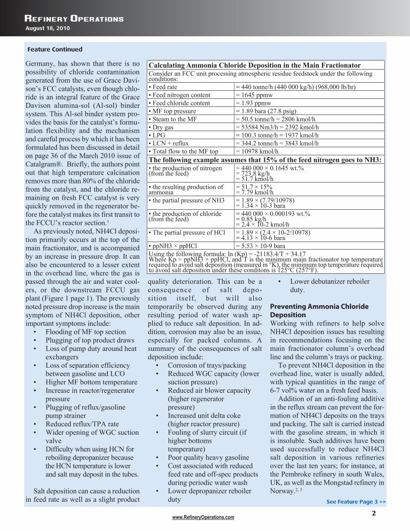
Calculating Ammonia Chloride Deposition in the Main FractionatorConsider an FCC unit processing atmospheric residue feedstock under the following conditions:• Feed rate = 440 tonne/h (440 000 kg/h) (968,000 lb/hr)• Feed nitrogen content = 1645 ppmw• Feed chloride content = 1.93 ppmw• MF top pressure = 1.89 bara (27.8 psig)• Steam to the MF = 50.5 tonne/h = 2806 kmol/h• Dry gas = 53584 Nm3/h = 2392 kmol/h• LPG = 100.3 tonne/h = 1937 kmol/h• LCN + reflux = 344.2 tonne/h = 3843 kmol/h• Total flow to the MF top = 10978 kmol/hThe following example assumes that 15% of the feed nitrogen goes to NH3:• the production of nitrogen (from the feed)
= 440 000 × 0.1645 wt.%= 723.8 kg/h= 51.7 kmol/h
• the resulting production of ammonia
= 51.7 × 15%= 7.79 kmol/h
• the partial pressure of NH3 = 1.89 × (7.79/10978)= 1.34 × 10⁻³ bara
• the production of chloride (from the feed)
= 440 000 × 0.000193 wt.%= 0.85 kg/h= 2.4 × 10⁻² kmol/h
• The partial pressure of HCl = 1.89 × (2.4 × 10-2/10978)= 4.13 × 10⁻⁶ bara
• ppNH3 × ppHCl = 5.53 × 10⁻⁹ baraUsing the following formula: ln (Kp) = -21183.4/T + 34.17Where Kp = ppNH3 × ppHCl, and T is the minimum main fractionator top temperature required to avoid salt deposition (measured in °K), the minimum top temperature required to avoid salt deposition under these conditons is 125°C (257°F).
See Feature Page 3 >>

Refinery Operations
3www.RefineryOperations.com
August 18, 2010
Feature Continued
These additives are now considered established and effective technology. They are also said to protect against corrosion. Another recommendation is to water wash the main fractionator. Water is injected either periodically or (more rarely) continuously in the reflux stream, and the main fraction-ator top temperature is reduced to ap-proximately 80°C (176°F) using the reflux rate or the tip top pumparound, to allow water to condense inside the column to dissolve the salt. The water is preferably removed on a dedicated tray, where it is separated from the heavy cracked naphtha.
This procedure has been successfully practiced by Saudi Aramco.4 Alterna-tively, the main fractionator top tem-perature can be increased (for instance, to above 135°C (275°F)) for a given period of time to enable dissociation of the salt. Obviously, this results in a full-range gasoline leaving overhead during the time period.
Other recommendations include improving water settling in imported feed tanks by allowing more time and the use of additives. Hardware modi-fications could include the design of the main fractionator’s reflux distribu-tor to avoid cold spots at the top of the column. Alternatively, the main frac-tionator’s tray design could be revised. For example, the installation of a water boot in one of the trays will allow water (and the dissolved salt) to be removed without contaminating the heavy cracked naphtha.
The installation of a two-stage de-salter could also be considered to op-timize crude desalter unit operation. Other options include installation of a dedicated FCC feed desalter, or instal-lation of a gasoline splitter and then col-lecting the thermally cracked naphtha overhead of the main fractionator.5
Finally, a very effective solution is to hydrotreat the FCC feed, as this re-moves most of the feed chloride and significantly improves yield struc-ture. However, this requires a large capital investment.
In summary, the main methods for managing NH4Cl deposition include:
• Use of anti-fouling additives• MF water washing• Higher MF top temperature• Improved water settling in im-
ported feed tanks• Modification of MF reflux dis-
tributor to avoid cold spots at the top of the column
• Installation of a water boot in one of the MF trays
• Installation of a two-stage crude desalter
• Installation of a FCC feed desalter
• Installation of a gasoline splitter• Hydrotreating the FCC feed• Avoid adding FCC catalyst in
a zone where it can bypass the regenerator bed.
Other Types of Salt DepositionThe other main types of salt depo-sition are from ammonium hydro-sulfide (NH4SH) and iron sulfide (FeS). The deposition of ammonium hydrosulfide is controlled by the equilibrium reaction:
NH3 (g) + H2S (g) ↔ (NH4)SH (s)
and takes place at a lower temperature than for ammonium chloride.6 Deposi-tion of this salt is most likely to occur in the overhead line coolers and sometimes in the wet gas compressor itself, partic-ularly when processing feeds with high nitrogen and sulfur content. The depo-sition of (NH4)SH is best controlled by adjusting the temperature where the deposition occurs, as well as by the use of a water wash. Iron sulfide is a corro-sion product, which, to a large extent, is found on main fractionator trays and packing. Since the salt is pyrophoric, its accumulation is a potential hazard dur-ing the opening of the column. It has been reported that the additives used to prevent NH4Cl deposition also help prevent the accumulation of FeS in the main fractionator. Proper procedures for shutdown of the FCCU, and the
application of a chemical wash to oxidize the FeS prior to vessel entry, should be considered.7
ConclusionVarious operational problems can arise when salt deposition occurs in FCC gas concentration units. The main type of salt deposited is NH4Cl and there is a range of likely causes, with the increased processing of imported at-mospheric residue being a major con-tributor. The vast majority of FCCUs using alumina-sol (Al-Sol) based FCC catalysts never experience problems due to the chloride content associated with this binder. It is important to clar-ify, moreover, that there are a number of ways to manage and solve any issues of NH4Cl deposition.
Indeed, various refineries have en-listed the support of the Grace Davison Refining Technologies technical ser-vice team with respect to chloride man-agement, so that they can avoid having to change to a chloride-free FCC cata-lyst, with the resulting sacrifice in per-formance and economics.
Literature Cited1. Melin, M., Baillie, C. and McEl-
hiney, G., “Salt Deposition in FCC Gas Concentration Units,” Catal-gram®, Issue No. 107, Spring 2010, p. 36.
2. Mott, R. W., “Troubleshooting FCC Standpipe Flow Problems.” Catalagram® publication No. 83, pps. 25-35, 1992.
3. Minyard, W. F., and Martin, D. O., “Removal and Prevention of Salt Fouling in FCC Main Fraction-ators,” ERTC Conference, Rome, Italy, Nov. 13-15, 2000.
4. Minyard, W. F., and Martin, D. O., Hansen, A. S., Synnevag, L., “FCC Main Fractionator Salt Fouling So-lutions,” Hydrocarbon Engineer-ing, March, 2000.
5. Dean, C., Golden, S. W., “Main Fractionator Water Wash Sys-tems,” PTQ Revamps, p.23-25.
See Feature Page 4 >>

Refinery Operations
4www.RefineryOperations.com
August 18, 2010
Feature Continued
6. Xiaodong, Y. E., “Gasoil Desalt-ing Reduces Chlorides in Crude,” Oil and Gas Journal, Oct 16, 2000, p.76-78.
7. Yiing, M. W., “Calculations Esti-mate Process Stream Depositions,” Oil and Gas Journal, Jan 3, 1994, p.38-41.
8. Ender, C., and Laird, D., “Reduce the Risk of Fire During Distillation Column Maintenance,” World Re-fining, November 2002, p.30-35.
Note: This article is based on a paper published in the Grace Davison
Catalgram®, Issue No. 107, Spring 2010, pp.s 34-40.
The AuthorsMichel Melin is Director, Techni-cal Service, Grace Davison Refining Technologies, Europe, Middle East, Africa and is based in the Worms, Germany offices of Grace Davison ([email protected]).
Colin Baillie is Marketing Man-ager, Grace Davison Refining Tech-nologies, Europe, Middle East, Africa and is based in the Worms,
Germany offices of Grace Davison ([email protected]).
Gordon McElhiney is Director of Marketing and Business Devel-opment, Grace Davison Refining Technologies, Europe, Middle East, Africa and is based in the Worms, Germany offices of Grace Davison ([email protected]). n
Refining TechnologyFCC Fourth Stage SeparatorsProjections of additional fourth stage separator projects (FSS) have been cur-tailed for 2010 due to lack of available capital and the corresponding reduction in refinery and FCCU utilization rates. However, this is not without saying that as more refiners approach 50 mg/Nm3 particulate emissions constraints or limi-tation on particulate matter in microns (e.g., PM10, or 10 microns particulate matter), it is expected that interest in FSS investments will increase in late 2011, as they are significantly less expensive than
electrostatic precipitators (ESPs). The FSS systems typically comprise
3-5% of the total third stage separator (TSS) mass flow. Interest in adding an FSS directly downstream from the TSS is also due to the refiner’s interest in sep-aration of virtually all erosive particles in order to safeguard power recovery expanders. Even in the event of a re-generator cyclone failure, the combined TSS/FSS system provides a safeguard against corrosive particulates (catalyst fines, etc.) for power recovery units.
In expectation of more stringent particulate emissions enforcement in the future, some of the major power recovery unit suppliers have part-nered with suppliers of TSS and FSS technology to provide additional ser-vices related to maintaining FCCU performance, including higher tem-perature piping design and expansion joints, integrated control and condi-tion monitoring systems and improved corrosion coatings. n
Increasing Main Fractionator and Debutanizer EfficiencySulzer Chemtech in conjunction with Shell Global Solutions report that the proprietary Shell ConSep trays have a capacity up to 80% higher than con-ventional trays and up to 50% higher than any other high performance tray while also maintaining high mass trans-fer efficiency. These trays have now been successfully tested at independent Fractionation Research Institute (F.R.I.).
As most column designs are a bal-ance of efficiency, capacity and en-ergy consumption, an improvement in the certainty of tower efficiency
would lead to improvement in the pro-cess design and design of the internals for the column.
According to information available from Sulzer Chemtech, the ConSep trays utilize the principle of de-entrain-ment by centrifugal force to remove the gravitational limitation of jet flood. Separation of the entrained liquid be-fore entering the next tray allows very high vapor velocities to be achieved in the column. The ConSep tray com-bines the large bubbling area and liq-uid handling capacity of the contacting
Shell HiFi trays and a centrifugal sepa-rator in a single stage (i.e., Con(tact) and Sep(arator)).
The trays have been successfully ap-plied in systems with vapor-to-liquid ratios close to unity, such as main frac-tionators and debutanizers. Application at low tray spacing can provide lower reboiler and condenser duties. Accord-ing to information available from Sul-zer Chemtech, several debutanizers and a hydrocracking unit main fractionator have been fitted with ConSep trays in recent years. n

Refinery Operations
5www.RefineryOperations.com
August 18, 2010
Predicting FCC Yields
Accurately predicting FCC yields re-quires as much information as possible about the feed properties used to cali-brate the FCC model. For example, at the 2008, NPRA Q&A, Aspen Tech-nology, Inc.’s Ed MacNeel pointed out that to be able to identify whatever spe-cies are in the feed, a minimum amount of information is required, including feed source (e.g., VGO, coker gas oil,
resid, synthetic crudes, hydrotreated gas oils, etc.), feed gravity and distilla-tion of the feed (D2887 for the heavier feeds or D1160).
Mac Neel noted that other impor-tant product properties needed to de-termine FCC product yields include sulfur content, total nitrogen, feed car-bon and metals including nickel and vanadium, which are typically the most
important, followed by copper, iron, and sodium. He and other panelists went on to explain why aromaticity is a very important aspect in determining FCC yields. Other panelists empha-sized that catalyst properties, unit hard-ware and operating conditions should also be taken into consideration when calibrating the model. n
Weighing the benefits of a Grassroots Coker Project or a RevampWhen refinery margins began to drop in the fourth quarter of 2008, the eco-nomics of grassroots coker investments resulted in less favorable econom-ics than initially expected. In contrast, coker revamps can be more accu-rately estimated because the scope is smaller. Information from Process En-gineering Associates, LLC and Adams
Project Managers, Inc., who have teamed up to perform coker revamp and modernization studies, show that re-vamps typically involve installing new larger sized drums, deheading valves, and other modernization upgrades for perhaps only one-third (1/3) of the cost of a grassroots coker, especially when offsite systems and site development
costs are considered. For example, they noted that outside battery limit (OSBL) investments for grassroots cokers are generally higher than most estimates indicate and can be a significant per-centage of the overall capital project cost (20-40%). n
Reducing Heavy Coker Gas Oil Filtration CostsDahlman Industrial Group has dem-onstrated the feasibility of using gas assisted backflush technology in com-bination with a special type of filter element to reduce heavy coker gas oil (HCGO) filtration costs. In one specific case, Dahlman engineers noted that a refiner was using a common backwash filter for HCGO filtration, which op-erates with short cycles and thus con-sumes too much backwash liquid - a
cost factor for the refiner. Additionally, the filter needed to be cleaned ex situ driving up the cost even further.
After consultation with the refiner, a basic design was made by Dahlman for a gas assisted backflush filter. The project was approved by the refiner to be designed and fabricated provided a pilot test would be done on site to dem-onstrate the process performance of the industrial design. The test demonstrated
that the selected filter media worked. The newly designed filter was field proven, demonstrating six hour filter cycle times versus 30-60 minutes on the original backwash filter.
According to Dahlman engineers, it can be concluded that the new design can solve many operational problems at refineries with delayed coker units and other feed filtration processes. n
Controlling Hydrocracker Runaway ReactionsEmergency depressuring to control hy-drocracker temperature runaways is be-coming more automated, as has been discussed at length from the perspective of various industry experts, including Gary Hawkins with Emerson Process Man-agement at the 2009 NPRA Q&A and in a white paper by Edward Marszal with Kinexis Consulting.
In the Marszal white paper, various operating scenarios that can lead to a tem-perature runaway were discussed at length, along with the recommended safety
instrumented function (SIF) methodology to best control each potential scenario. For example, Marszal wrote that during a re-cycle compressor failure, the flow rate of hydrogen through the reactor decreases. The decrease in the hydrogen flow rate affects the hydrogen-to-hydrocarbon ratio of the feed and also will stop the flow of quench gas.
When this occurs, the heat removal with excess hydrogen stops, but the reac-tion continues to occur because there is still ample hydrogen available at a high
pressure. Because the rate of heat removal loss is so great, it is virtually impossible for an operator to prevent a runaway reaction from starting, therefore requiring depressuring.
The level of automation involved in the initial depressuring steps is less of a manu-ally controlled process as SIF systems are implemented in these high pressure, high temperature units. In this case, depressuring will occur due to either the low recycle gas flow SIF, which activates the slow depres-suring upon loss of recycle flow, or manual activation of the slow depressuring. n
Refinery Operations
6www.RefineryOperations.com
August 18, 2010
PROCESSING & OPERATIONS Q&AHeater Thermal Efficiency
Charles E. Baukal, Jr., Ph.D., P.E., Director, John Zink Institute, John Zink Company, LLC, [email protected]:Refiners should still be able to main-tain high burner efficiencies and low emissions at 85% run rates as long as they make the proper adjustments to the burner air registers and stack dampers to maintain the target excess O2 and draft levels. When reducing the fir-ing rates for the lower run rates, they should preferably reduce the firing rate to all burners in a heater, rather than turn some burners off (referred to as burners-out-of-service or BOOS) while having others at a high rate. The out-of-service burners tend to have high air leaking through the burner air registers (even closed they can leak up to 10% or more air), which usually adversely affects overall heater performance.
Gary Hawkins, Emerson Process Management, Global Refining Business Consultant, [email protected]:One common hurdle to overcome when implementing control strategies to im-prove process fired heater energy ef-ficiency by reducing the excess air is the absence of “knobs to turn.” That is, most of the fired heaters in established facilities are natural draft heaters that have manual actuation of the burner registers and likely the flue gas damper too. Reducing the excess air in these heaters would require adjustment of the registers by personnel in the field, at the burner, usually under the heater while it is running. This may be considered a hassle if the adjustment is temporary plus it raises safety concerns.
Automating the dampers and air reg-isters with SMART actuators provides
the ability to adjust air as needed from the control room by an operator or auto-mated control strategy, with the added benefit of self running diagnostics for display in the control room or desig-nated maintenance groups that can alert personnel when problems are detected.
In addition, SMART combustion flue gas analyzers can reliably pro-vide feedback that the process opera-tor or automation strategy is making the right moves.
These smart instruments and actuator systems allow access to the field device from the control room or maintenance asset management station, which can re-duce the number of trips to the field and when required, can assist the technician to minimize time in the field to work on a device that may likely be in a hot, hard to reach location. n
The latest Dow Jones newswires provides a cursory list of the FCCUs, CDUs, cokers, etc. in North America and Europe that are operating at utilization rates below 85%. What practical steps should be considered for adjusting thermal systems (i.e., furnaces in CDUs,hydrocrackers, etc.) to run as efficiently as possible? What automation systems can you suggest for improving efficiency and monitoring emissions?
AUTOMATIONAvoiding Pump Failures with Advanced Monitoring SystemsAvoiding loss of production as a result of a pump failure can be avoided through integration of vibration data into process control. This principle is outlined in detail in the article “Anatomy of a Pump Failure and How It Could Have Been Prevented” – as featured in Pumps and Systems and archived at www.pump-zone.com.
Briefly, the article tells the story of a high-speed centrifugal pump which failed catastrophically, resulting in production losses and significant re-pair costs. The failure occurred when the pump inboard bearing lost lubrica-tion, overheated and eventually seized. The unfortunate part of the story is that this pump had been equipped with an
automated vibration monitoring system about four months, which accurately provided advance warning.
“Emerson offers multiple options to integrate vibration into the process au-tomation system,” per Robert Skeirik, product manager for Emerson’s Wireless Vibration Transmitter, “the user needs to decide what type and level of infor-mation is required based on their appli-cation.” In this case, field transmitters were providing overall and PeakVue™ values back to the control room for trend-ing and alarming. According to Skeirik, the monitoring system provided repeated alarms over the four day period between when the onset of the problem and the
point where the pump failed. The system progressed through three
levels of alerts (advisory, maintenance, and failure), indicating the increasing severity of the fault; however, they went unnoticed by control room personnel. As detailed in the article, the condition of the pump deteriorated rapidly in the final ten minutes before failure. Even though the integration of vibration into the con-trol system functioned as designed, the alerts were simply lost among the vol-ume of other alarms regis-tering in the control room. n
Refinery Operations
7www.RefineryOperations.com
August 18, 2010
Assessing Compressor Train PerformanceTwo new diagnostic modules for the EnvisionTM suite of condition monitor-ing software from Dresser-Rand Group Inc. work individually or in tandem to provide information that helps increase machinery availability, improve pro-ductivity and reduce operating costs.
The Envision Compressor Perfor-mance Module (CPM) provides op-erators with real-time and historical centrifugal compressor performance calculations. Data are primarily gath-ered from the plant’s existing control interface to minimize installation time and cost. With Envision CPM, users as-sess the compressor train’s performance relative to factory determined perfor-mance maps. This information allows operational and maintenance activities to be planned ahead of a required shut down, reducing the impact on produc-tion and enabling corrective action to be
determined before servicing the compressor.The second module, Dresser-Rand’s
Envision Health for Journal Bearings Vibration Analysis, aids in the early detection of incipient problems in ro-tating equipment –as much as one to nine months before a problem deterio-rates to unit failure or lost production. By having advanced warning and prob-lem diagnosis, equipment operators can once again plan ahead for operation and maintenance activities.
“Traditional rotating equipment control systems provide only average overall vibration level indications and simple machine protection functions. When comprehensive vibration diag-nostics are required, often two or more separate systems must be added,” said Dan Levin, general manager, Dresser-Rand Control Systems. “Dresser-Rand’s Envision software eliminates the
need for separate systems by combining machinery control and operations with performance and diagnostics.”
By adding Envision CPM and Envi-sion Health to a standard D-R control system, the modules provide a single interoperable platform that combines all machine monitoring needs into one program. With a simple point and click of the mouse, the user can easily move from operations to diagnostic screens.
The reporting tool allows users to select from multiple formats of graphs, or create trends from historical data. Alarms can be sent to designated e-mail addresses. All graphs, data and views are available remotely through a web-based interface running on a standard PC. Since the Envision software suite offers worldwide access, users can work with the modules whether they’re stationed on-site or elsewhere. n
INDUSTRY NEWSValero Reports Profitable 2nd QuarterValero Energy Corporation recently reported income from continuing op-erations of $530 million, or $0.93 per share, for the second quarter of 2010, compared to a loss from continuing op-erations of $191 million, or $0.36 per share, for the second quarter of 2009. For the six months ended June 30, 2010, income from continuing operations was $429 million, or $0.76 per share, com-pared to income from continuing opera-tions of $173 million, or $0.33 per share for the six months ended June 30, 2009.
Operating income in the second quar-ter of 2010 was $921 million, versus an operating loss of $192 million in the
second quarter of 2009. The $1.1 bil-lion increase in operating income was mainly due to higher margins for diesel and many of the company’s second-ary products, such as petrochemicals, asphalt, and lube oils, as well as better discounts for low-quality feedstocks.
“It’s great to be profitable again,” said Valero Chairman and CEO Bill Klesse. “Our second quarter results re-ally showed the earnings power of our assets. Our system of high-conversion refineries was able to take advantage of higher margins on products and wider discounts on sour crude oils. Another highlight is that our refining operating
expenses for the second quarter fell to $3.55 per barrel, which was our low-est cost per barrel since the second quarter of 2009.”
Commenting on the outlook for re-fining, Klesse said, “So far in the third quarter, product margins and feedstock discounts have continued at relatively good levels, although down from the second quarter in most of our regions. We remain cautiously optimistic that global economic expansion will drive growth in refined-products demand. Valero makes and sells fuels, so we need consumers to get back to work and the economy to grow faster.” n
High Activity Coke Selective FCC CatalystGrace Davison, an operating segment of W. R. Grace & Co. has introduced its Alcyon™ fluid catalytic cracking (FCC) catalyst specifically developed for applications that require maximum
activity and conversion. “Alcyon™ catalyst reflects our
continuing commitment to deliver-ing a broad portfolio of FCC catalysts and additives. It is the latest of eleven
new refining products introduced since 2008 by our R&D group,” com-mented Shawn Abrams, Vice President and General Manager, Grace Davison
See Catalyst Page 8 >>
Refinery Operations
8www.RefineryOperations.com
August 18, 2010
Accessing Feed Properties to Predicting FCC YieldsAccurately predicting FCC yields requires as much information as pos-sible about the feed properties used to calibrate the FCC model in use. At the 2008, NPRA Q&A, Aspen Technology, Inc.’s Ed MacNeel pointed out that to be able to identify whatever species are in the feed, a minimum amount of in-formation is required, that includes feed source (e.g., VGO, coker gas oil, etc.), feed gravity and distillation of the feed
(ASTM-D2887 for the heavier feeds or ASTM-D1160).
The ASTM-D2887 is designed to de-termine boiling range distribution of pe-troleum products and fractions having a final boiling point of 1000 °F (538°C) or lower. Mac Neel noted that other important product properties needed to determine FCC product yields include sulfur content, total nitrogen, feed car-bon, and metals including nickel and
vanadium, which are typically the most important, followed by copper, iron, and sodium. He and other panelists went on to explain why aromaticity is a very important aspect in determining FCC yields. Other panelists empha-sized that catalyst properties, unit hard-ware and operating conditions should also be taken into consideration when calibrating the model. n
Enhancing Zeolite Technology Used in FCC CatalystsRive Technology Inc. announced in early August that it has entered into an agree-ment with W.R. Grace & Co.-Conn., the primary U.S. operating company of W.R. Grace & Co.
Rive and Grace will jointly develop and commercialize Rive’s zeolite technology for use in catalysts for FCC processes.
Rive’s proprietary technology makes zeolite catalysts more accessible to hy-drocarbon molecules, resulting in in-creased yields of transportation fuels and less coke. The technology creates refinery-wide operating flexibility due to enhanced coke selectivity. Refiners can profit from the improved catalytic
performance by increasing refinery throughput, processing heavier crude oil, and maximizing production of high quality fuels.
Under the agreement, Rive and Grace will develop, manufacture and market FCC catalysts incorporating Rive’s technology worldwide. n
Improved Mass Transfer Equipment Rating ProgramKoch-Glitsch has recently announced that Version 4.0 of its KG-TOWER® equipment rating program is now avail-able for download. This electronic de-sign tool can assist in the specification of mass transfer equipment, including conventional and high performance valve trays and conventional and high performance random ansd structured tower packings. New features include:
• Sieve tray design/rating capability • Updated tray models• Support for PRO/II 8.1 files in
Simulation import feature• Ability to rate additional pack-
ing products• INTALOX® ULTRA™ ran-
dom packing• Full complement of FLEXIGRID®
severe service packing sizes.
In addition, usability improvements provide the ability to specify minimum and maximum loadings. More tray defi-nition sketches are available along with updated Help files, including more sup-port for the simulation import feature. Additional information can be found at www.koch-glitsch.com. n
Processing Highly Acidic Crude OilSINOPEC Research Institute of Petroleum Processing has recently reported a break-through in the research and application of
technology for processing highly acidic crude oil. Sinopec Gaoqiao Petrochemical Company has increased its profit by 0.13
billion RMB by using this technology. Ac-cording to SINOPEC sources, further de-tails will become available later in 2010. n
Catalyst Continued
Refining Technologies. “Like all our FCC catalysts and additives, Alcyon™ catalyst’s revolutionary technology and performance are supported by our strong technical service and flexible manufacturing system.”
Joanne Deady, Vice President of Global Marketing, Grace Davison, stated “Alcyon™ catalyst delivers
increased activity yet preserves the coke selectivity benefits. The catalyst im-proves conversion by enhancing the rate of cracking within the catalyst particle.”
Alcyon™ contains a proprietary zeo-lite modification that delivers the high-est activity of any catalytic technology with a low surface area per kinetic con-version. An added benefit of the new
zeolite is superior activity retention that has been verified in field performance. It is particularly well suited for refiners looking to re-optimize unit operation to maximize profitability yet remain within operating limits. For any given coke yield, the catalyst achieves higher conversion, maximizing total FCC barrels to the refinery gasoline pool. n
Refinery Operations
9www.RefineryOperations.com
August 18, 2010
EDITORIAL COMMENTWaiting for More Hydrogen
Second quar-ter earnings for certain re-finers show a positive slope in profitability for several re-finers in vari-ous parts of the world. A steady increase for
refined product in Central Asia, the Middle East and other areas parallels growth in other industries outside petro-leum refining, such as pharmaceuticals and food processing.
Refinery planning will still favor revamps in many regions over grass root projects. Compressor upgrades, improved furnace efficiency, more ex-tensive use of refractory applications (e.g., FCCU transfer lines) are planned for revamps scheduled in the late 2010 and into 2011.
No doubt, hesitation on regulatory driven projects weighs in heavily on hydrogen related projects.
Hydrogen production has become a priority in current refinery operations. In many refineries, hydroprocessing capacity and the associated H2 network is limiting refinery throughput and op-erating margins. Furthermore, higher H2 purities within the refinery network are becoming more important to boost hydrotreater capacity and lengthen catalyst life cycles.
Hydrogen is usually manufac-tured by the steam methane reforming (SMR) process. In some cases partial
oxidation has also been used, particularly where heavy oil is available at low cost. Steam reform-ing of natural gas offers an efficient, economical, and widely used process for hydrogen production. The efficiency of the steam re-forming process is about 65% to 75%, among the highest of current com-mercially available pro-duction methods. The cost of hydrogen produced by SMR is closely related to natural gas prices and is currently the least expensive among all bulk hydrogen production technologies.
However, during the production of hydrogen, CO2 is also produced. The SMR process in centralized plants emits more than twice the CO2 than hydrogen produced. To avoid emission of CO2 into the atmosphere, CO2 can be con-centrated, captured, and sequestered; sequestration concepts and technologies are relatively new, which is perhaps one of the reasons that refiners are still hesi-tant to commit to the high level of in-vestment required for SMRs and related carbon capture systems.
Take for example the efforts of a major hydrogen producer and licen-sor of SMR technology, Air Products, which has recently received a $253 million from the US government to work out ways to capture CO2 from steam methane reformers, which make hydrogen from natural gas.
The funding has been received from the United States Department of En-ergy (DOE) under the Industrial Car-bon Capture and Sequestration (ICCS) Program. The funding will be used for final engineering, design, construction and operation of the project through September 2015.
Air Products will design, construct and operator a system to capture car-bon dioxide from its two steam meth-ane reformers at the Valero Refinery in Port Arthur, Texas. The reformers of course generate hydrogen which is used by nearby refineries. The CO2 will then be used for enhanced oil re-covery in nearby oil fields operated by Denbury Resources, being transported by the Denbury Green Pipeline. The company estimates that approximately one million tons of CO2 annually will be recovered, purified and delivered via the pipeline. n
Rene Gonzalez, Editor, Refinery Operations

Refinery Operations
10www.RefineryOperations.com
August 18, 2010
Rene Gonzalez, EditorRefinery OperationsPO Box 11283Spring TX [email protected]: +1 713 449 5817Office: +1 281 257 0582Fax: +1 281 686 5846www.refineryoperations.com
Copyright 2010 by Refinery Operations. Reproduction pro-hibited except for further use by the purchaser and expressly prohibited for resale. This information is obtained from the public domain and the intelligence of the staff of Refinery Operations. While every effort is taken to ensure accuracy, it cannot be guaranteed that this information has not been su-perseded. Refinery Operations cannot be held liable for the results of actions taken based upon this information.
contact us
Yes, I want the latest in Refinery Operations delivered directly to my inbox!
Please start my one-year subscription to Refinery Operations newsletter for only $995 $739
Name: ________________________________ Company: _______________________________ Phone: ____________________________________ Email: __________________________________
Please allow four to six weeks for your first issue to arrive.
Refinery Operations is emailed on the 1st and 3rd Monday of each month.
Calendar of Events
AUGUST24-25 NPRA Cat Cracking Conference, Houston, +1 202 457 0480, www.npra.org.
SEPTEMBER23-24 Russia & CIS Refining Technology Conference & Ex-hibition, Moscow, +7 495 517 77 09, +7 495 662 33 87 (fax), [email protected], www.europetro.com.
OCTOBER10-13 NPRA Q&A and Technology Forum, Baltimore, (202) 457-0480, www.npra.org.
19 ERTC Energy Efficiency Conference, Amsterdam, +31 (0) 20 62 34 255; (fax) +31 (0) 20 62 52 997, www.gtforum.com.
NOVEMBER29 Nov- 1Dec. ERTC 15th Annual Meeting, Istanbul, +44 (0) 207 484 9700, www.gtforum.com.