audio engineering society convention paper 7215 · 2007-10-11 · 2.3. file format headers the 3gpp...
TRANSCRIPT

Audio Engineering Society
Convention Paper 7215Presented at the 123rd Convention
2007 October 5–8 New York, NY, USA
The papers at this Convention have been selected on the basis of a submitted abstract and extended precis that have been peer reviewed by at least two qualified anonymous reviewers. This convention paper has been reproduced from the author's advance manuscript, without editing, corrections, or consideration by the Review Board. The AES takes no responsibility for the contents. Additional papers may be obtained by sending request and remittance to Audio Engineering Society, 60 East 42nd Street, New York, New York 10165-2520, USA; also see www.aes.org. All rights reserved. Reproduction of this paper, or any portion thereof, is not permitted without direct permission from the Journal of the Audio Engineering Society.
A Very Low Bit Rate Protection Layer to Increase the Robustness of the AMR-WB+
Codec against Bit Errors Philippe Gournay
Université de Sherbrooke, 2500 boul. de l’Université, Sherbrooke (Québec) J1K 2R1 Canada [email protected]
ABSTRACT
Audio codecs face various channel impairments when used in challenging applications such as digital radio. The standard AMR-WB+ audio codec includes a concealment procedure to handle lost frames. It is also inherently robust to bit errors, although some bits within any given frame are more sensitive than others. Motivated by this observation, the present paper makes two contributions. First, a detailed study of the sensitivity of individual bits in AMR-WB+ frames is provided. All the bits in a frame are then divided into three sensitivity classes so that efficient unequal error protection (UEP) schemes can be designed. Then, a very low bit rate protection layer to increase the robustness of the codec against bit errors is proposed and assessed using the results of subjective audio quality tests. Remarkably, in contrast to the standard codec, where some errors have a very discernable effect, the protection layer ensures that the decoded audio is free of major channel artifacts even at a significant 0.5% bit error rate.
1. INTRODUCTION
The AMR-WB+ audio codec [1-3] uses a hybrid coding model that switches automatically, depending on the characteristics of the input signal, between an ACELP (Algebraic Code-Excited Linear Prediction) and a TCX (Transform Coded eXcitation) coding model. AMR-WB+ performs well for speech as well as for music, accepts both mono and stereo inputs, accommodates a wide audio bandwidth range (from 8 to 48 kHz), and is scalable in bit rate from 6 to 36 kbps for mono and 7 to 48 kbps for stereo encoding. Moreover, it is backward compatible with the AMR-WB/G.722.2 standard [4],
which was the first speech codec to be adopted for both wireless and wireline services.
AMR-WB+ was standardized in 2004 for streaming and multimedia messaging services in Global System for Mobile communications (GSM) and Third Generation (3G) cellular systems by the 3rd Generation Partnership Project (3GPP). This codec has also been standardized as a low bit rate audio option for DVB-H Mobile TV applications [5]. Currently, because of its excellent performance at low bit rates, AMR-WB+ is also drawing increasing interest for other applications such as digital radio.
P. Gournay AMR-WB+ Protection Layer Against Bit Errors
AES 123rd Convention, New York, NY, USA, 2007 October 5–8 Page 2 of 18
Depending on the application, audio codecs have to face various channel impairments that typically translate into lost frames/packets and/or bit errors. AMR-WB+ includes a frame loss concealment procedure to help mitigate the impact of lost frames. AMR-WB+ is also inherently robust to bit errors. However, as with any other codec, some bits within a given frame are more sensitive, in the sense that errors in these bits have a greater impact on the degradation of the decoded and perceived sound quality, than others.
With this in mind, the present paper makes two contributions. First, a detailed study of the sensitivity of individual bits in AMR-WB+ frames is provided. This information is required to design efficient unequal error protection (UEP) schemes. Then, a very low bit rate protection layer is proposed to increase the robustness of the codec to bit errors, and it is assessed using subjective audio quality tests. The protection layer adds only a few bits to the AMR-WB+ frame, which typically contain hundreds of bits of encoded audio.
This paper is organized as follows. Section 2 gives the necessary insight into the AMR-WB+ codec architecture and bitstream structure. Section 3 presents the results of the bit sensitivity study, including a classification of AMR-WB+ bitstream frames into three sensitivity classes. The protection scheme is then presented in section 4. Finally, the results of a subjective quality evaluation are presented in section 5 and conclusions are drawn in section 6.
2. THE AMR-WB+ CODEC
This section gives a brief overview of the AMR-WB+ codec, emphasizing its multi-mode nature, its flexible variable-length frame structure, and the embedded organization of its bitstream.
2.1. Overview of the codec
AMR-WB+ is a hybrid codec that switches between a time-domain coding model and a transform-domain coding model. The time domain coding model is actually the AMR-WB 3GPP mandatory standard for wideband speech communication [4] (also standardized by the ITU-T as G.722.2), which is a multi-rate codec for wideband speech sampled at 16 kHz that uses ACELP (Algebraic Code Excited Linear Prediction). The transform coding model is called Transform Coded eXcitation (TCX) [6] and is designed to switch seamlessly to and from the ACELP coding model.
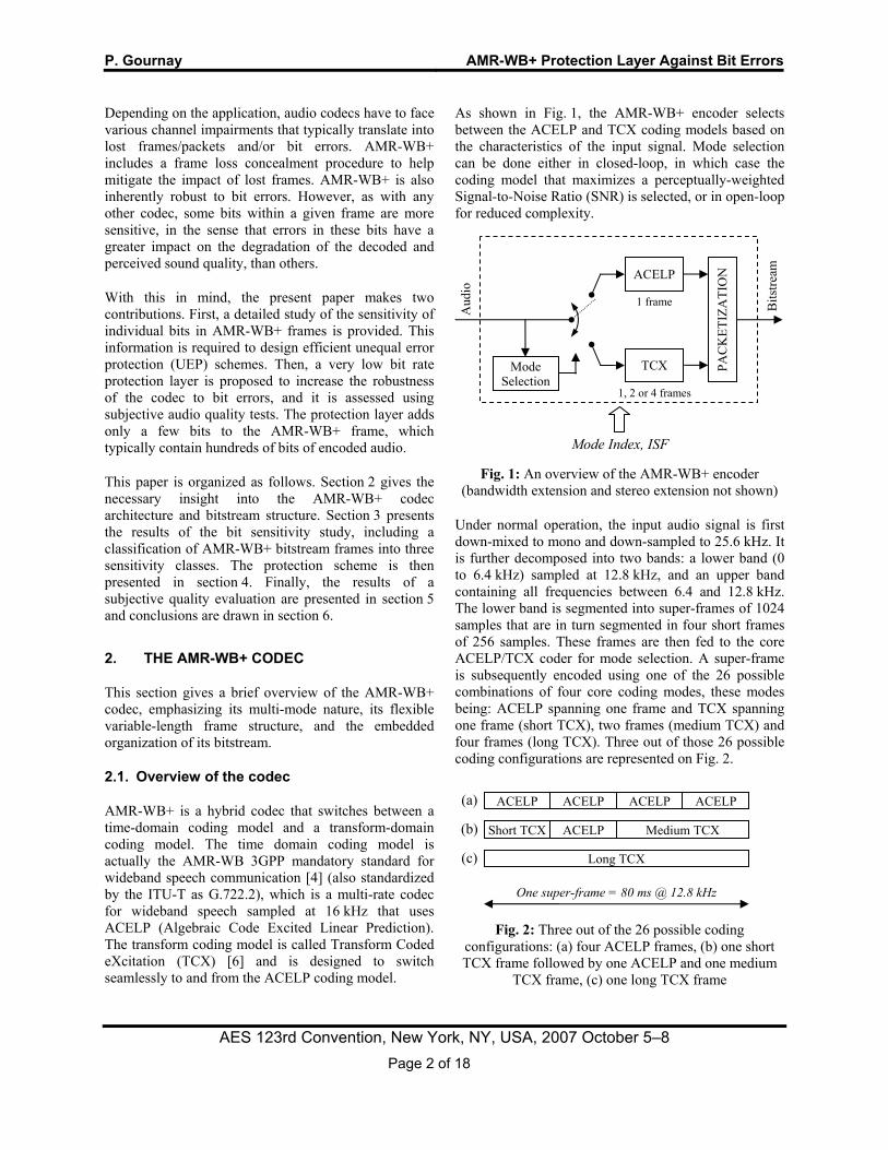
As shown in Fig. 1, the AMR-WB+ encoder selects between the ACELP and TCX coding models based on the characteristics of the input signal. Mode selection can be done either in closed-loop, in which case the coding model that maximizes a perceptually-weighted Signal-to-Noise Ratio (SNR) is selected, or in open-loop for reduced complexity.
Fig. 1: An overview of the AMR-WB+ encoder
(bandwidth extension and stereo extension not shown)
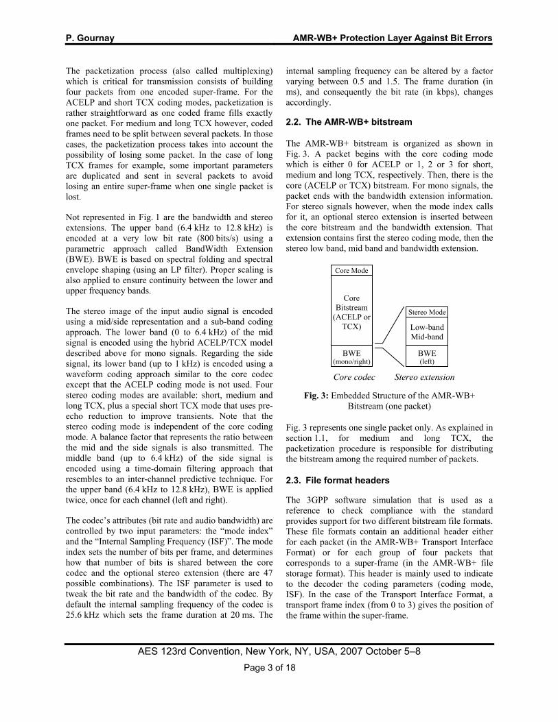
Under normal operation, the input audio signal is first down-mixed to mono and down-sampled to 25.6 kHz. It is further decomposed into two bands: a lower band (0 to 6.4 kHz) sampled at 12.8 kHz, and an upper band containing all frequencies between 6.4 and 12.8 kHz. The lower band is segmented into super-frames of 1024 samples that are in turn segmented in four short frames of 256 samples. These frames are then fed to the core ACELP/TCX coder for mode selection. A super-frame is subsequently encoded using one of the 26 possible combinations of four core coding modes, these modes being: ACELP spanning one frame and TCX spanning one frame (short TCX), two frames (medium TCX) and four frames (long TCX). Three out of those 26 possible coding configurations are represented on Fig. 2.
Fig. 2: Three out of the 26 possible coding
configurations: (a) four ACELP frames, (b) one short TCX frame followed by one ACELP and one medium
TCX frame, (c) one long TCX frame
ACELP ACELP ACELP ACELP
Short TCX ACELP Medium TCX
Long TCX
One super-frame = 80 ms @ 12.8 kHz
(a)
(b)
(c)
Mode Selection
PAC
KET
IZA
TIO
N
Bits
tream
ACELP
TCX
Aud
io
1, 2 or 4 frames
1 frame
Mode Index, ISF
P. Gournay AMR-WB+ Protection Layer Against Bit Errors
AES 123rd Convention, New York, NY, USA, 2007 October 5–8 Page 3 of 18
The packetization process (also called multiplexing) which is critical for transmission consists of building four packets from one encoded super-frame. For the ACELP and short TCX coding modes, packetization is rather straightforward as one coded frame fills exactly one packet. For medium and long TCX however, coded frames need to be split between several packets. In those cases, the packetization process takes into account the possibility of losing some packet. In the case of long TCX frames for example, some important parameters are duplicated and sent in several packets to avoid losing an entire super-frame when one single packet is lost.
Not represented in Fig. 1 are the bandwidth and stereo extensions. The upper band (6.4 kHz to 12.8 kHz) is encoded at a very low bit rate (800 bits/s) using a parametric approach called BandWidth Extension (BWE). BWE is based on spectral folding and spectral envelope shaping (using an LP filter). Proper scaling is also applied to ensure continuity between the lower and upper frequency bands.
The stereo image of the input audio signal is encoded using a mid/side representation and a sub-band coding approach. The lower band (0 to 6.4 kHz) of the mid signal is encoded using the hybrid ACELP/TCX model described above for mono signals. Regarding the side signal, its lower band (up to 1 kHz) is encoded using a waveform coding approach similar to the core codec except that the ACELP coding mode is not used. Four stereo coding modes are available: short, medium and long TCX, plus a special short TCX mode that uses pre-echo reduction to improve transients. Note that the stereo coding mode is independent of the core coding mode. A balance factor that represents the ratio between the mid and the side signals is also transmitted. The middle band (up to 6.4 kHz) of the side signal is encoded using a time-domain filtering approach that resembles to an inter-channel predictive technique. For the upper band (6.4 kHz to 12.8 kHz), BWE is applied twice, once for each channel (left and right).
The codec’s attributes (bit rate and audio bandwidth) are controlled by two input parameters: the “mode index” and the “Internal Sampling Frequency (ISF)”. The mode index sets the number of bits per frame, and determines how that number of bits is shared between the core codec and the optional stereo extension (there are 47 possible combinations). The ISF parameter is used to tweak the bit rate and the bandwidth of the codec. By default the internal sampling frequency of the codec is 25.6 kHz which sets the frame duration at 20 ms. The
internal sampling frequency can be altered by a factor varying between 0.5 and 1.5. The frame duration (in ms), and consequently the bit rate (in kbps), changes accordingly.
2.2. The AMR-WB+ bitstream
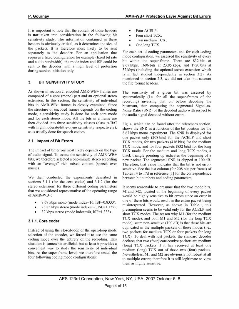
The AMR-WB+ bitstream is organized as shown in Fig. 3. A packet begins with the core coding mode which is either 0 for ACELP or 1, 2 or 3 for short, medium and long TCX, respectively. Then, there is the core (ACELP or TCX) bitstream. For mono signals, the packet ends with the bandwidth extension information. For stereo signals however, when the mode index calls for it, an optional stereo extension is inserted between the core bitstream and the bandwidth extension. That extension contains first the stereo coding mode, then the stereo low band, mid band and bandwidth extension.
Fig. 3: Embedded Structure of the AMR-WB+
Bitstream (one packet)
Fig. 3 represents one single packet only. As explained in section 1.1, for medium and long TCX, the packetization procedure is responsible for distributing the bitstream among the required number of packets.
2.3. File format headers
The 3GPP software simulation that is used as a reference to check compliance with the standard provides support for two different bitstream file formats. These file formats contain an additional header either for each packet (in the AMR-WB+ Transport Interface Format) or for each group of four packets that corresponds to a super-frame (in the AMR-WB+ file storage format). This header is mainly used to indicate to the decoder the coding parameters (coding mode, ISF). In the case of the Transport Interface Format, a transport frame index (from 0 to 3) gives the position of the frame within the super-frame.
Core Mode
Core Bitstream
(ACELP or TCX)
BWE (mono/right)
BWE (left)
Low-band Mid-band
Stereo Mode
Stereo extensionCore codec
P. Gournay AMR-WB+ Protection Layer Against Bit Errors
AES 123rd Convention, New York, NY, USA, 2007 October 5–8 Page 4 of 18
It is important to note that the content of those headers is not taken into consideration in the following bit sensitivity study. The information contained in these headers is obviously critical, as it determines the size of the packets. It is therefore most likely to be sent separately to the decoder. For an application that requires a fixed configuration for example (fixed bit rate and audio bandwidth), the mode index and ISF could be sent to the decoder with a high level of protection during session initiation only.
3. BIT SENSITIVITY STUDY
As shown in section 2, encoded AMR-WB+ frames are composed of a core (mono) part and an optional stereo extension. In this section, the sensitivity of individual bits in AMR-WB+ frames is closely examined. Since the structure of encoded frames depends on the coding mode, a sensitivity study is done for each core mode and for each stereo mode. All the bits in a frame are then divided into three sensitivity classes (class A/B/C with high/moderate/little-or-no sensitivity respectively), as is usually done for speech codecs.
3.1. Impact of Bit Errors
The impact of bit errors most likely depends on the type of audio signal. To assess the sensitivity of AMR-WB+ bits, we therefore selected a one-minute stereo recording with an “average” rich mixed content (speech over music).
We then conducted the experiments described in sections 3.1.1 (for the core codec) and 3.1.2 (for the stereo extension) for three different coding parameters that we considered representative of the operating range of AMR-WB+:
• 8.67 kbps mono (mode index=16, ISF=0.8333); • 23.85 kbps stereo (mode index=37, ISF=1.125); • 32 kbps stereo (mode index=40, ISF=1.333).
3.1.1. Core coder
Instead of using the closed-loop or the open-loop mode selection of the encoder, we forced it to use the same coding mode over the entirety of the recording. This situation is somewhat artificial, but at least it provides a convenient way to study the sensitivity of individual bits. At the super-frame level, we therefore tested the four following coding mode configurations:
• Four ACELP; • Four short TCX; • Two medium TCX; • One long TCX.
For each set of coding parameters and for each coding mode configuration, we assessed the sensitivity of every bit within the super-frame. There are 832 bits at 8.67 kbps, 1696 bits at 23.85 kbps, and 1920 bits at 32 kbps (including the optional stereo extension which is in fact studied independently in section 3.2). As mentioned in section 2.3, we did not take into account the file format headers.
The sensitivity of a given bit was assessed by systematically (i.e. for all the super-frames of the recording) inversing that bit before decoding the bitstream, then computing the segmental Signal-to-Noise Ratio (SNR) of the decoded audio with respect to the audio signal decoded without errors.
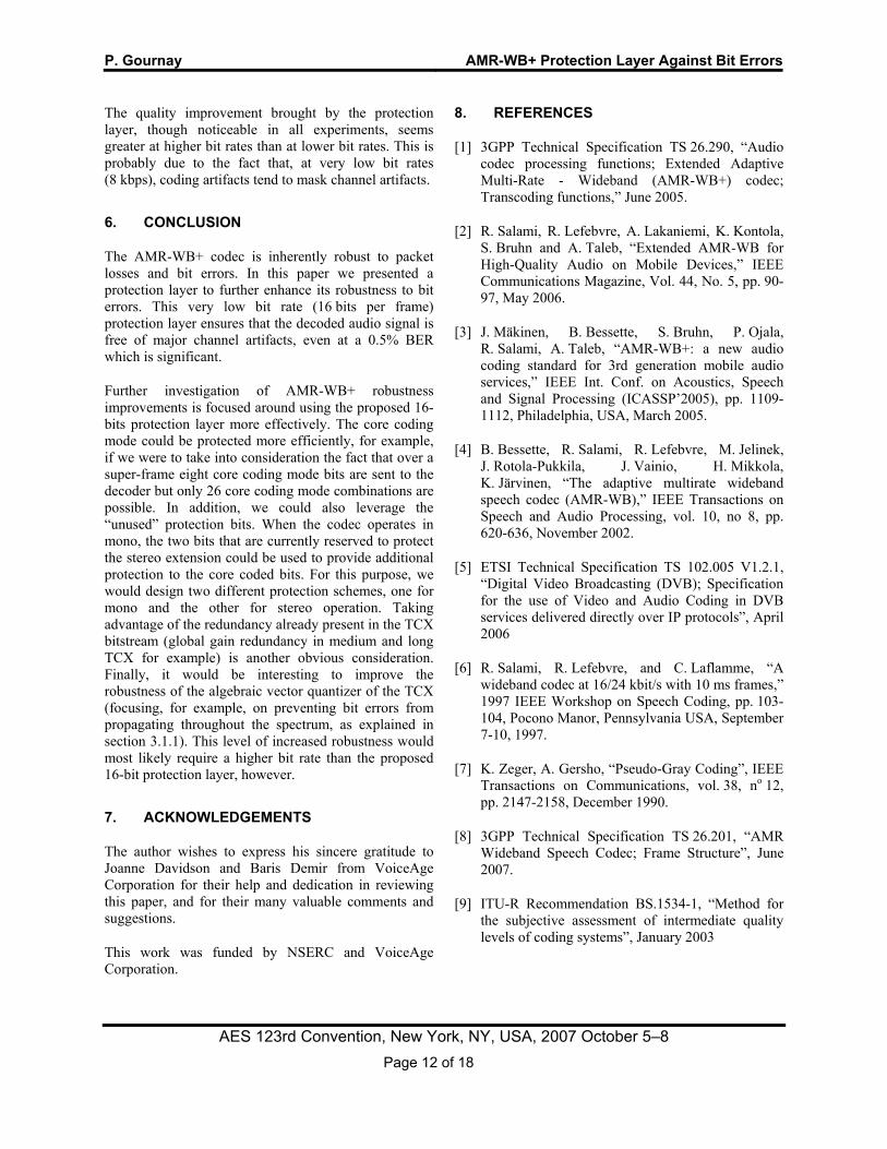
Fig. 4, which can be found after the references section, shows the SNR as a function of the bit position for the 8.67 kbps mono experiment. The SNR is displayed for one packet only (208 bits) for the ACELP and short TCX modes, for two packets (416 bits) for the medium TCX mode, and for four packets (832 bits) for the long TCX mode. For the medium and long TCX modes, a black triangle pointing up indicates the beginning of a new packet. The segmental SNR is clipped at 100 dB. Therefore, that value indicates that the bit is not error-sensitive. See the last column (for 208 bits per frame) of Tables 14 to 17d in reference [1] for the correspondence between bit numbers and coding parameters.
It seems reasonable to presume that the two mode bits, M1and M2, located at the beginning of every packet would be highly sensitive to bit errors since an error in one of these bits would result in the entire packet being misinterpreted. However, as shown in Table 1, this presumption seems to be valid only for the ACELP and short TCX modes. The reason why M1 (for the medium TCX mode), and both M1 and M2 (for the long TCX mode), seem non-sensitive (100 dB) is that these bits are duplicated in the multiple packets of these modes (i.e., two packets for medium TCX or four packets for long TCX). To deal with lost packets, the standard decoder declares that two (four) consecutive packets are medium (long) TCX packets if it has received at least one medium (long) TCX out of those two (four) packets. Nevertheless, M1 and M2 are obviously not robust at all to multiple errors; therefore it is still legitimate to view them as highly sensitive.
P. Gournay AMR-WB+ Protection Layer Against Bit Errors
AES 123rd Convention, New York, NY, USA, 2007 October 5–8 Page 5 of 18
ACELP Short TCX
Medium TCX
Long TCX
M1 M2 0 0 0 1 1 0 1 1 M1 1.38 -1.93 100.00 100.00 M2 6.27 45.66 -0.75 100.00
Average 28.09 59.81 46.50 24.57
Table 1: Sensitivity (segmental SNR in dB) of the first (M1) and second (M2) bits of the mode compared to the
average bit sensitivity (8.67 kbps mono)
On average, the ACELP mode appears to be highly sensitive to bit errors as demonstrated by the top curve in Fig. 4. This is mainly because of the extensive use it makes of prediction. For ACELP, the most sensitive parameters are: 1. the first subvectors of the multistage ISP (Immitance Spectral Pairs) quantizer, which are located at the beginning of the packet; 2. the pitch value (also called the adaptive codebook index); and 3. the joint gain quantizer. These last two parameters are transmitted four times per frame (once per subframe), and the subframe structure is clearly apparent on the SNR curve.
For the TCX, the most sensitive parameters are the first subvectors of the LPC quantizer, and the global gain. The measured sensitivity of Algebraic Vector Quantizer (ΑVQ) bits, which make up the largest component of the bitstream, is highly variable. At 8.67 kbps mono and in the short TCX mode, AVQ bits are located between bit numbers 58 and 191. As it can be seen on curve (b) of Fig. 4, the sensitivity of AVQ bits decreases gradually (increasing SNR) until roughly bit position 150, then increases steadily (decreasing SNR) until bit 191 which is the last AVQ bit. The difference in SNR between the most and least sensitive AVQ bits is more than 20 dB which is far from marginal.
This wide range of sensitivity can be explained by the way the TCX codec operates. The audio signal is first windowed and frequency transformed. The resulting set of “frequency bins”, which are complex-valued, are grouped four by four and quantized as a series of 8-dimensional vectors called “subvectors”. Depending on the window length (short, medium or long), the spectrum is organized in interlaced “tracks” of subvectors (one track in short TCX, two tracks in medium TCX, and four tracks in long TCX). Apart from the special “overflow” case where one track encroaches on another packet, each track of AVQ-quantized subvectors is normally packetized in its own packet.
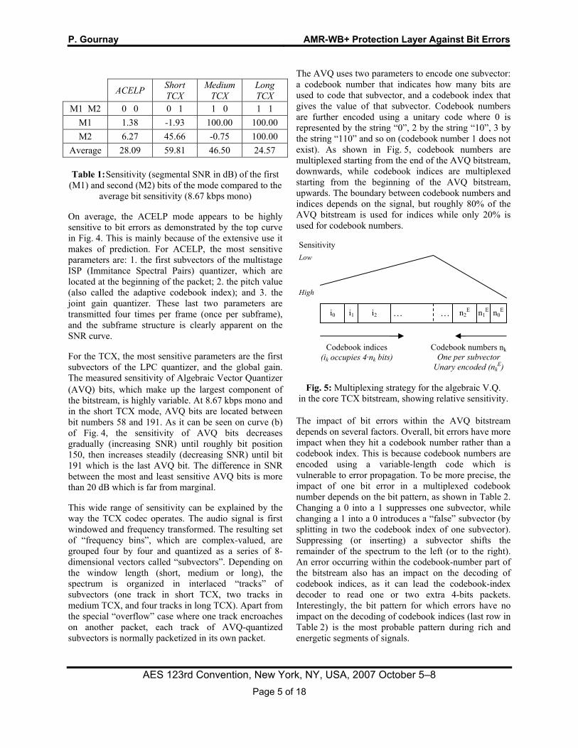
The AVQ uses two parameters to encode one subvector: a codebook number that indicates how many bits are used to code that subvector, and a codebook index that gives the value of that subvector. Codebook numbers are further encoded using a unitary code where 0 is represented by the string “0”, 2 by the string “10”, 3 by the string “110” and so on (codebook number 1 does not exist). As shown in Fig. 5, codebook numbers are multiplexed starting from the end of the AVQ bitstream, downwards, while codebook indices are multiplexed starting from the beginning of the AVQ bitstream, upwards. The boundary between codebook numbers and indices depends on the signal, but roughly 80% of the AVQ bitstream is used for indices while only 20% is used for codebook numbers.
Fig. 5: Multiplexing strategy for the algebraic V.Q.
in the core TCX bitstream, showing relative sensitivity.
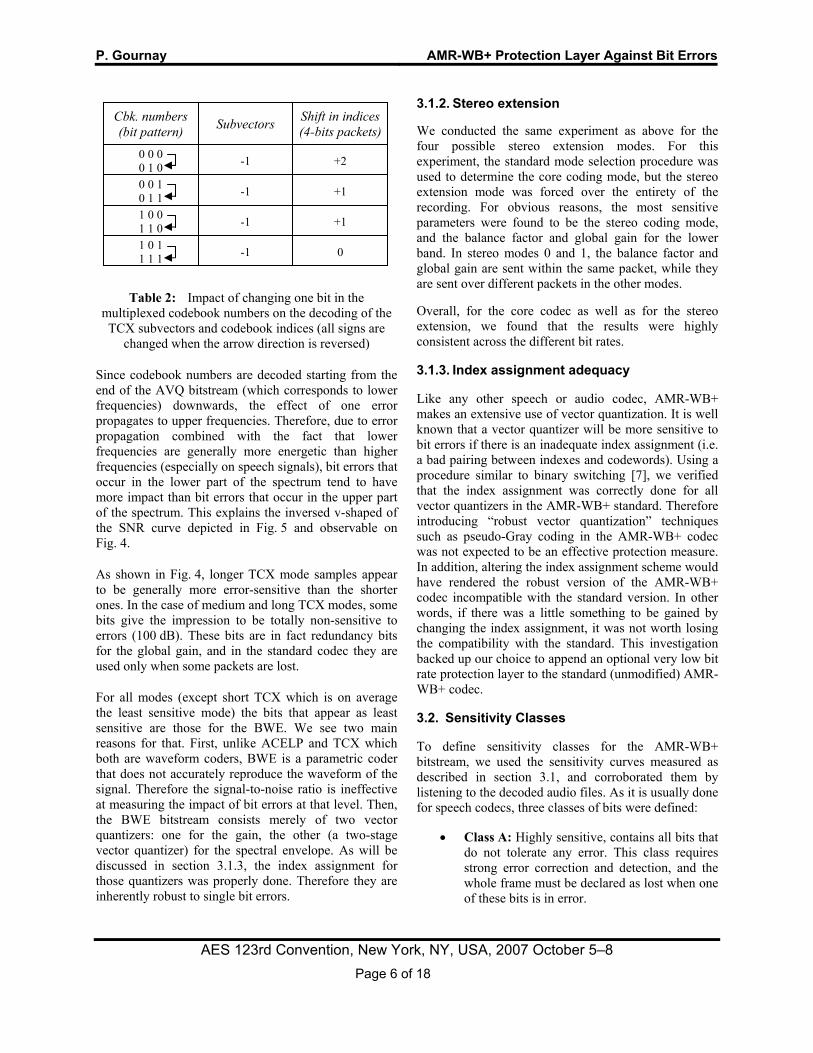
The impact of bit errors within the AVQ bitstream depends on several factors. Overall, bit errors have more impact when they hit a codebook number rather than a codebook index. This is because codebook numbers are encoded using a variable-length code which is vulnerable to error propagation. To be more precise, the impact of one bit error in a multiplexed codebook number depends on the bit pattern, as shown in Table 2. Changing a 0 into a 1 suppresses one subvector, while changing a 1 into a 0 introduces a “false” subvector (by splitting in two the codebook index of one subvector). Suppressing (or inserting) a subvector shifts the remainder of the spectrum to the left (or to the right). An error occurring within the codebook-number part of the bitstream also has an impact on the decoding of codebook indices, as it can lead the codebook-index decoder to read one or two extra 4-bits packets. Interestingly, the bit pattern for which errors have no impact on the decoding of codebook indices (last row in Table 2) is the most probable pattern during rich and energetic segments of signals.
i0 i1 i2 n0En1
En2E ……
Codebook indices (ik occupies 4·nk bits)
Sensitivity
Low
High
Codebook numbers nkOne per subvector
Unary encoded (nkE)
P. Gournay AMR-WB+ Protection Layer Against Bit Errors
AES 123rd Convention, New York, NY, USA, 2007 October 5–8 Page 6 of 18
Table 2: Impact of changing one bit in the multiplexed codebook numbers on the decoding of the TCX subvectors and codebook indices (all signs are
changed when the arrow direction is reversed)
Since codebook numbers are decoded starting from the end of the AVQ bitstream (which corresponds to lower frequencies) downwards, the effect of one error propagates to upper frequencies. Therefore, due to error propagation combined with the fact that lower frequencies are generally more energetic than higher frequencies (especially on speech signals), bit errors that occur in the lower part of the spectrum tend to have more impact than bit errors that occur in the upper part of the spectrum. This explains the inversed v-shaped of the SNR curve depicted in Fig. 5 and observable on Fig. 4.
As shown in Fig. 4, longer TCX mode samples appear to be generally more error-sensitive than the shorter ones. In the case of medium and long TCX modes, some bits give the impression to be totally non-sensitive to errors (100 dB). These bits are in fact redundancy bits for the global gain, and in the standard codec they are used only when some packets are lost.
For all modes (except short TCX which is on average the least sensitive mode) the bits that appear as least sensitive are those for the BWE. We see two main reasons for that. First, unlike ACELP and TCX which both are waveform coders, BWE is a parametric coder that does not accurately reproduce the waveform of the signal. Therefore the signal-to-noise ratio is ineffective at measuring the impact of bit errors at that level. Then, the BWE bitstream consists merely of two vector quantizers: one for the gain, the other (a two-stage vector quantizer) for the spectral envelope. As will be discussed in section 3.1.3, the index assignment for those quantizers was properly done. Therefore they are inherently robust to single bit errors.
3.1.2. Stereo extension
We conducted the same experiment as above for the four possible stereo extension modes. For this experiment, the standard mode selection procedure was used to determine the core coding mode, but the stereo extension mode was forced over the entirety of the recording. For obvious reasons, the most sensitive parameters were found to be the stereo coding mode, and the balance factor and global gain for the lower band. In stereo modes 0 and 1, the balance factor and global gain are sent within the same packet, while they are sent over different packets in the other modes.
Overall, for the core codec as well as for the stereo extension, we found that the results were highly consistent across the different bit rates.
3.1.3. Index assignment adequacy
Like any other speech or audio codec, AMR-WB+ makes an extensive use of vector quantization. It is well known that a vector quantizer will be more sensitive to bit errors if there is an inadequate index assignment (i.e. a bad pairing between indexes and codewords). Using a procedure similar to binary switching [7], we verified that the index assignment was correctly done for all vector quantizers in the AMR-WB+ standard. Therefore introducing “robust vector quantization” techniques such as pseudo-Gray coding in the AMR-WB+ codec was not expected to be an effective protection measure. In addition, altering the index assignment scheme would have rendered the robust version of the AMR-WB+ codec incompatible with the standard version. In other words, if there was a little something to be gained by changing the index assignment, it was not worth losing the compatibility with the standard. This investigation backed up our choice to append an optional very low bit rate protection layer to the standard (unmodified) AMR-WB+ codec.
3.2. Sensitivity Classes
To define sensitivity classes for the AMR-WB+ bitstream, we used the sensitivity curves measured as described in section 3.1, and corroborated them by listening to the decoded audio files. As it is usually done for speech codecs, three classes of bits were defined:
• Class A: Highly sensitive, contains all bits that do not tolerate any error. This class requires strong error correction and detection, and the whole frame must be declared as lost when one of these bits is in error.
Shift in indices (4-bits packets)Subvectors Cbk. numbers
(bit pattern)
+2 -1 0 0 0 0 1 0
+1 -1
-1
-1
+1
0
0 0 1 0 1 1 1 0 0 1 1 0 1 0 1 1 1 1

P. Gournay AMR-WB+ Protection Layer Against Bit Errors
AES 123rd Convention, New York, NY, USA, 2007 October 5–8 Page 7 of 18
• Class B: Moderately sensitive, contains all bits that exhibit potentially significant sensitivity to errors. Under error-prone conditions, bits belonging to this class might require a certain level of error correction. But contrary to Class A bits, frames can be decoded even with a certain level of residual errors in Class B bits.
• Class C: Not sensitive, contains bits that are not sensitive enough to require any protection against errors.
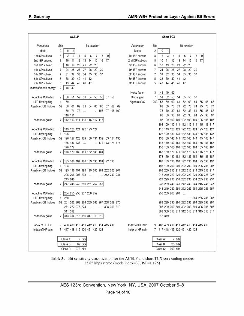
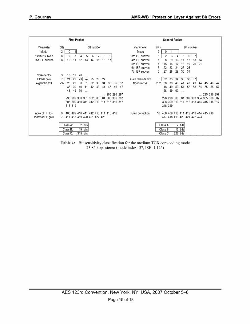
Sensitivity classes for the ACELP and the short, medium and long TCX modes are given in Tables 3 to 5. Sensitivity classes for the stereo extension modes 0 (short TCX without pre-echo reduction) to 3 (long TCX) are given in Tables 6 to 8. These tables (which can be found at the end of the paper) represent the 23.85 kbps coding configuration only, but their generalization to any other coding configuration is rather straightforward. The main differences between the various rates are the number of algebraic-codebook bits (for ACELP) and the number of AVQ bits (for TCX and stereo extension) which both depend on the mode index. All those bits fall within the least sensitive class C.
3.2.1. Comparison to AMR-WB bit classification
For the ACELP mode, the classification we give is similar to the classification defined by the 3GPP for the AMR-WB standard [8]. However, there are also some notable differences. First of all, the AMR-WB classification does not make use of class C. For example, in the AMR-WB codec at 15.85 kbps (which forms the core of our 23.85 kbps configuration), 72 bits out of the 317 bits that compose a frame fall within class A. All remaining bits fall within class B. We shifted all bits one class down (A to B and B to C) and created a more sensitive class populated only by the mode bits. The remaining differences are minor. First, the AMR-WB bitstream includes a Voice Activity Detection (VAD) bit classed as sensitive (class A) which does not exist in the AMR-WB+ bitstream. Conversely, the AMR-WB+ ACELP bitstream includes a two-bit “mean energy” parameter which does not exist in the AMR-WB bitstream and which we classed as sensitive (class B). Finally, concerning the ISP (Immitance Spectral Pairs) quantizer, we intentionally reduced the number of bits declared as sensitive so that class B for ACELP is not too big when compared to the same class for other coding modes. In comparison with AMR-WB, we removed bits 11 and 13 to 16 (2nd ISP
subvector), bits 24 to 27 (4th ISP subvector), and bit 32 (5th ISP subvector) from the “error-sensitive” class.
4. THE VERY LOW BIT RATE PROTECTION LAYER
This section presents the very low bit rate protection layer. The standard AMR-WB+ bitstream frame is kept unchanged, but an extra layer of 16 bits per frame is added to allow for error detection and correction at the decoder. The protection scheme depends on both the core and the stereo coding modes.
4.1. Protection of the core coder
The protection layer includes 14 bits for error detection or detection/correction of the core codec. The exact use of these bits depends on the core coding mode.
4.1.1. The core protection layer
The core coding mode (class A bits) is protected by the customized Hamming-like systematic block code shown in Table 9. The codeword length is 6 (two mode bits located in the core bitstream and four redundancy bits sent in the protection layer). The minimum Hamming distance for this code is 4, which means that single bit errors can be detected and corrected, and that double bit errors can be detected but not corrected. Codewords containing three or more bit errors cannot be corrected properly and will result with an erroneous core coding mode.
Mode Mode (binary) Redundancy
0 0 0 0 0 0 0 1 0 1 0 1 1 1 2 1 0 1 0 1 1 3 1 1 1 1 0 0
Table 9: Error detecting and correcting code used to protect the core coding mode
Since the core coding mode is by far the most sensitive parameter, the probability of having residual errors at that level is a critical consideration. Suppose that bit errors are uniformly distributed within the bitstream, with p the bit error probability. The probability of having k errors within n bits is:
,)1( knkkn ppC −− (1)
P. Gournay AMR-WB+ Protection Layer Against Bit Errors
AES 123rd Convention, New York, NY, USA, 2007 October 5–8 Page 8 of 18
where knC is the number of k-combinations from a set
with n elements:
.)!(!
!knk
nC kn −= (2)
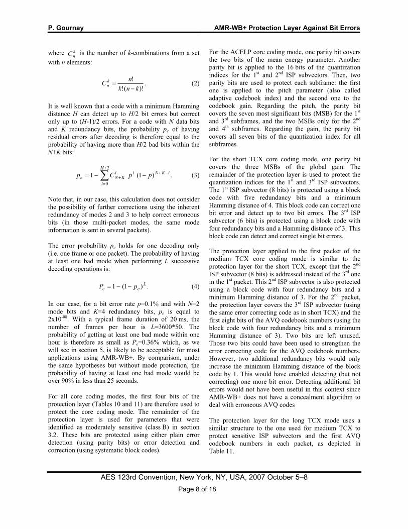
It is well known that a code with a minimum Hamming distance H can detect up to H/2 bit errors but correct only up to (H-1)/2 errors. For a code with N data bits and K redundancy bits, the probability pe of having residual errors after decoding is therefore equal to the probability of having more than H/2 bad bits within the N+K bits:
.)1(12/
0∑=
−++ −−=
H
i
iKNiiKNe ppCp (3)
Note that, in our case, this calculation does not consider the possibility of further corrections using the inherent redundancy of modes 2 and 3 to help correct erroneous bits (in those multi-packet modes, the same mode information is sent in several packets).
The error probability pe holds for one decoding only (i.e. one frame or one packet). The probability of having at least one bad mode when performing L successive decoding operations is:
.)1(1 Lee pP −−= (4)
In our case, for a bit error rate p=0.1% and with N=2 mode bits and K=4 redundancy bits, pe is equal to 2x10-08. With a typical frame duration of 20 ms, the number of frames per hour is L=3600*50. The probability of getting at least one bad mode within one hour is therefore as small as Pe=0.36% which, as we will see in section 5, is likely to be acceptable for most applications using AMR-WB+. By comparison, under the same hypotheses but without mode protection, the probability of having at least one bad mode would be over 90% in less than 25 seconds.
For all core coding modes, the first four bits of the protection layer (Tables 10 and 11) are therefore used to protect the core coding mode. The remainder of the protection layer is used for parameters that were identified as moderately sensitive (class B) in section 3.2. These bits are protected using either plain error detection (using parity bits) or error detection and correction (using systematic block codes).
For the ACELP core coding mode, one parity bit covers the two bits of the mean energy parameter. Another parity bit is applied to the 16 bits of the quantization indices for the 1st and 2nd ISP subvectors. Then, two parity bits are used to protect each subframe: the first one is applied to the pitch parameter (also called adaptive codebook index) and the second one to the codebook gain. Regarding the pitch, the parity bit covers the seven most significant bits (MSB) for the 1st and 3rd subframes, and the two MSBs only for the 2nd and 4th subframes. Regarding the gain, the parity bit covers all seven bits of the quantization index for all subframes.
For the short TCX core coding mode, one parity bit covers the three MSBs of the global gain. The remainder of the protection layer is used to protect the quantization indices for the 1st and 3rd ISP subvectors. The 1st ISP subvector (8 bits) is protected using a block code with five redundancy bits and a minimum Hamming distance of 4. This block code can correct one bit error and detect up to two bit errors. The 3rd ISP subvector (6 bits) is protected using a block code with four redundancy bits and a Hamming distance of 3. This block code can detect and correct single bit errors.
The protection layer applied to the first packet of the medium TCX core coding mode is similar to the protection layer for the short TCX, except that the 2nd ISP subvector (8 bits) is addressed instead of the 3rd one in the 1st packet. This 2nd ISP subvector is also protected using a block code with four redundancy bits and a minimum Hamming distance of 3. For the 2nd packet, the protection layer covers the 3rd ISP subvector (using the same error correcting code as in short TCX) and the first eight bits of the AVQ codebook numbers (using the block code with four redundancy bits and a minimum Hamming distance of 3). Two bits are left unused. Those two bits could have been used to strengthen the error correcting code for the AVQ codebook numbers. However, two additional redundancy bits would only increase the minimum Hamming distance of the block code by 1. This would have enabled detecting (but not correcting) one more bit error. Detecting additional bit errors would not have been useful in this context since AMR-WB+ does not have a concealment algorithm to deal with erroneous AVQ codes
The protection layer for the long TCX mode uses a similar structure to the one used for medium TCX to protect sensitive ISP subvectors and the first AVQ codebook numbers in each packet, as depicted in Table 11.

P. Gournay AMR-WB+ Protection Layer Against Bit Errors
AES 123rd Convention, New York, NY, USA, 2007 October 5–8 Page 9 of 18
ACELP Short TCX Medium TCX
Packet 1 Packet 2 0
Mode redundancy
Mode redundancy
Mode redundancy
Mode redundancy
1 2 3 4 Mean energy Global gain Global gain
3rd ISP subvector
5 1st and 2nd ISP subvect.
1st ISP subvector
1st ISP subvector
6 Pitch SF1 7 Gain SF1 8 Pitch SF2 First 8 bits
of AVQ codebook numbers
9 Gain SF2 10 Pitch SF3
3rd ISP subvector
2nd ISP subvector
11 Gain SF3 12 Pitch SF4 unused 13 Gain SF4 unused
Table 10: Protection layer for the core coder: modes 0 (ACELP), 1 (short TCX) and 2 (medium TCX)
Long TCX
Packet 1 Packet 2 Packet 3 Packet 4 0
Mode redundancy
Mode redundancy
Mode redundancy
Mode redundancy
1 2 3 4 Global gain
3rd ISP subvector
First 8 bits of AVQ
codebook numbers
First 8 bits of AVQ
codebook numbers
5
1st ISP subvector
6 7 8 First 8 bits
of AVQ codebook numbers
Next 8 bits of AVQ
codebook numbers
Next 8 bits of AVQ
codebook numbers
9 10
2nd ISP subvector
11 12 unused unused unused 13 unused unused unused
Table 11: Protection layer for the core coder: mode 3 (long TCX)
4.1.2. Decoding of the core protection layer
How the AMR-WB+ decoder uses the protection layer to mitigate the effects of bit errors within the core bitstream is the focus of this subsection.
The AMR-WB+ decoder first uses the first four bits of the protection layer to detect and correct bit errors within the core coding mode. The mode is decoded (using a minimal distance criterion) for the four packets of the super-frame. A packet is declared as erased if an
error is detected but cannot be corrected. Then, the AMR-WB+ decoder uses the natural redundancy of core coding modes 2 and 3 to correct some of the residual errors (this is a part of the standard AMR-WB+ decoder): the core coding mode for the whole super-frame (four packets) is set to 3 if at least one valid (i.e. not erased) packet is in mode 3. The same procedure is used for mode 2, once for the first two packets and another time for the last two packets.
Packets that are declared as erased are concealed as provided by the standard AMR-WB+ decoder. Other packets are decoded using the normal decoding process.
During the decoding process, parity bits are checked right before the related parameter is decoded. When a parity bit indicates the presence of an error, the concealment procedure is used instead of the normal decoding procedure, but for that parameter only. This is equivalent to replacing the traditional bad frame indicator (BFI) by partial BFIs. Regarding parameters protected by a Hamming code, error correction is performed (using minimal distance decoding) right before decoding that parameter. When an error is detected but cannot be corrected, the appropriate concealment procedure is used instead of the normal decoding procedure, for that parameter only.
4.2. Protection of the stereo extension
The two remaining bits of the protection layer are used to protect the optional stereo extension. When the codec operates in mono, those two bits are left unused.
4.2.1. The stereo protection layer
The first bit is used to detect errors that may affect the stereo mode. A parity bit is not the best solution for that purpose, because some errors are more critical than others. Consider for example single bit errors affecting the stereo mode. Mistaking a mode 0 for a mode 1 (or vice versa) has very little impact on the decoding of the stereo extension, since the bit allocation is the same for those two modes (see Table 6). However, mistaking a mode 0 with a mode 2, or a mode 1 with a mode 3, is more critical as it can lead to a flawed decoding of the balance factor or the global gain. Mistaking a mode 2 for a mode 3 (or conversely) would also have serious consequences on the decoding of the stereo extension. This latter type of error, however, is less likely to happen because of the inherent redundancy of the mode bits in these multi-packet modes.
P. Gournay AMR-WB+ Protection Layer Against Bit Errors
AES 123rd Convention, New York, NY, USA, 2007 October 5–8 Page 10 of 18
Therefore, instead of including a parity bit which is independent of the type of error, the protection layer includes a control bit (0 for modes 0 and 1, and 1 for modes 2 and 3) to distinguish between single-packet modes and multi-packet modes. This control bit, in conjunction with the inherent redundancy for modes 2 and 3, gives a good level of protection for the stereo mode.
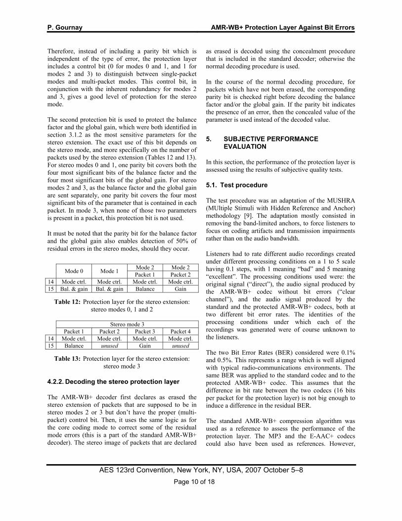
The second protection bit is used to protect the balance factor and the global gain, which were both identified in section 3.1.2 as the most sensitive parameters for the stereo extension. The exact use of this bit depends on the stereo mode, and more specifically on the number of packets used by the stereo extension (Tables 12 and 13). For stereo modes 0 and 1, one parity bit covers both the four most significant bits of the balance factor and the four most significant bits of the global gain. For stereo modes 2 and 3, as the balance factor and the global gain are sent separately, one parity bit covers the four most significant bits of the parameter that is contained in each packet. In mode 3, when none of those two parameters is present in a packet, this protection bit is not used.
It must be noted that the parity bit for the balance factor and the global gain also enables detection of 50% of residual errors in the stereo modes, should they occur.
Mode 0 Mode 1 Mode 2 Mode 2 Packet 1 Packet 2
14 Mode ctrl. Mode ctrl. Mode ctrl. Mode ctrl. 15 Bal. & gain Bal. & gain Balance Gain
Table 12: Protection layer for the stereo extension: stereo modes 0, 1 and 2
Stereo mode 3 Packet 1 Packet 2 Packet 3 Packet 4
14 Mode ctrl. Mode ctrl. Mode ctrl. Mode ctrl. 15 Balance unused Gain unused
Table 13: Protection layer for the stereo extension: stereo mode 3
4.2.2. Decoding the stereo protection layer
The AMR-WB+ decoder first declares as erased the stereo extension of packets that are supposed to be in stereo modes 2 or 3 but don’t have the proper (multi-packet) control bit. Then, it uses the same logic as for the core coding mode to correct some of the residual mode errors (this is a part of the standard AMR-WB+ decoder). The stereo image of packets that are declared
as erased is decoded using the concealment procedure that is included in the standard decoder; otherwise the normal decoding procedure is used.
In the course of the normal decoding procedure, for packets which have not been erased, the corresponding parity bit is checked right before decoding the balance factor and/or the global gain. If the parity bit indicates the presence of an error, then the concealed value of the parameter is used instead of the decoded value.
5. SUBJECTIVE PERFORMANCE EVALUATION
In this section, the performance of the protection layer is assessed using the results of subjective quality tests.
5.1. Test procedure
The test procedure was an adaptation of the MUSHRA (MUltiple Stimuli with Hidden Reference and Anchor) methodology [9]. The adaptation mostly consisted in removing the band-limited anchors, to force listeners to focus on coding artifacts and transmission impairments rather than on the audio bandwidth.
Listeners had to rate different audio recordings created under different processing conditions on a 1 to 5 scale having 0.1 steps, with 1 meaning “bad” and 5 meaning “excellent”. The processing conditions used were: the original signal (“direct”), the audio signal produced by the AMR-WB+ codec without bit errors (“clear channel”), and the audio signal produced by the standard and the protected AMR-WB+ codecs, both at two different bit error rates. The identities of the processing conditions under which each of the recordings was generated were of course unknown to the listeners.
The two Bit Error Rates (BER) considered were 0.1% and 0.5%. This represents a range which is well aligned with typical radio-communications environments. The same BER was applied to the standard codec and to the protected AMR-WB+ codec. This assumes that the difference in bit rate between the two codecs (16 bits per packet for the protection layer) is not big enough to induce a difference in the residual BER.
The standard AMR-WB+ compression algorithm was used as a reference to assess the performance of the protection layer. The MP3 and the E-AAC+ codecs could also have been used as references. However,

P. Gournay AMR-WB+ Protection Layer Against Bit Errors
AES 123rd Convention, New York, NY, USA, 2007 October 5–8 Page 11 of 18
when subjected to these bit error rate conditions these alternative codecs became ineffective and stopped operating. This is most likely due to their extensive reliance on variable-length coders such as Huffman coding. Notably however, neither the standard nor the protected AMR-WB+ decoder, exhibited this type of adverse behavior during the sensitivity study or when processing audio samples for the subjective test although they also make use of a variable-length coder (the unary code used for AVQ codebook numbers).
We conducted three separate experiments using three different coding configurations: 8.67 kbps mono (mode index=16, ISF=0.8333), 23.85 kbps stereo (mode index=37, ISF=1.125) and 32 kbps stereo (mode index=40, ISF=1.333). The 16-bits added for the protection layer raises the effective bit rates of these configurations to 9.33 kbps, 24.75 kbps and 33.07 kbps, respectively.
Each experiment was done using a set of 16 audio tracks, with four tracks belonging to each of the following four categories: speech, music, speech between music, and speech over music. The selected audio tracks were each between 5 and 10 seconds in duration.
Nine distinct experienced listeners participated in the test.
5.2. Test results
The mean scores obtained by the different processing conditions (taking all audio categories into account) are shown in Fig. 6 for the 8.67 kbps mono experiment, Fig. 7 for the 23.85 kbps stereo experiment and Fig. 8 for the 32 kbps stereo experiment.
In the 23.85 kbps experiment, the clear channel recording scores 4.2 on the 1 to 5 scale. At a 0.1% BER, the protection layer raises the score of the coded recording from 2.7 to 3.5. This means that the protection layer makes up for half of the quality degradation caused by bit errors. At a 0.5% BER, the protection layer raises the score from 1.47 to 2.17 which is also very significant. In the presence of bit errors, the output of the standard AMR-WB+ decoder (without the protection layer) is contaminated by some rather annoying channel artifacts (distortions or problems in the stereo image). The protection layer ensures that the decoded audio is free of major channel artifacts even at a 0.5% BER.
1
2
3
4
5
Fig. 6: Subjective test results for the
8.67 kbps mono experiment
1
2
3
4
5
Fig. 7: Subjective test results for the
23.85 kbps stereo experiment
1
2
3
4
5
Fig. 8: Subjective test results for the
32 kbps stereo experiment
P. Gournay AMR-WB+ Protection Layer Against Bit Errors
AES 123rd Convention, New York, NY, USA, 2007 October 5–8 Page 12 of 18
The quality improvement brought by the protection layer, though noticeable in all experiments, seems greater at higher bit rates than at lower bit rates. This is probably due to the fact that, at very low bit rates (8 kbps), coding artifacts tend to mask channel artifacts.
6. CONCLUSION
The AMR-WB+ codec is inherently robust to packet losses and bit errors. In this paper we presented a protection layer to further enhance its robustness to bit errors. This very low bit rate (16 bits per frame) protection layer ensures that the decoded audio signal is free of major channel artifacts, even at a 0.5% BER which is significant.
Further investigation of AMR-WB+ robustness improvements is focused around using the proposed 16-bits protection layer more effectively. The core coding mode could be protected more efficiently, for example, if we were to take into consideration the fact that over a super-frame eight core coding mode bits are sent to the decoder but only 26 core coding mode combinations are possible. In addition, we could also leverage the “unused” protection bits. When the codec operates in mono, the two bits that are currently reserved to protect the stereo extension could be used to provide additional protection to the core coded bits. For this purpose, we would design two different protection schemes, one for mono and the other for stereo operation. Taking advantage of the redundancy already present in the TCX bitstream (global gain redundancy in medium and long TCX for example) is another obvious consideration. Finally, it would be interesting to improve the robustness of the algebraic vector quantizer of the TCX (focusing, for example, on preventing bit errors from propagating throughout the spectrum, as explained in section 3.1.1). This level of increased robustness would most likely require a higher bit rate than the proposed 16-bit protection layer, however.
7. ACKNOWLEDGEMENTS
The author wishes to express his sincere gratitude to Joanne Davidson and Baris Demir from VoiceAge Corporation for their help and dedication in reviewing this paper, and for their many valuable comments and suggestions.
This work was funded by NSERC and VoiceAge Corporation.
8. REFERENCES
[1] 3GPP Technical Specification TS 26.290, “Audio codec processing functions; Extended Adaptive Multi-Rate - Wideband (AMR-WB+) codec; Transcoding functions,” June 2005.
[2] R. Salami, R. Lefebvre, A. Lakaniemi, K. Kontola, S. Bruhn and A. Taleb, “Extended AMR-WB for High-Quality Audio on Mobile Devices,” IEEE Communications Magazine, Vol. 44, No. 5, pp. 90-97, May 2006.
[3] J. Mäkinen, B. Bessette, S. Bruhn, P. Ojala, R. Salami, A. Taleb, “AMR-WB+: a new audio coding standard for 3rd generation mobile audio services,” IEEE Int. Conf. on Acoustics, Speech and Signal Processing (ICASSP’2005), pp. 1109-1112, Philadelphia, USA, March 2005.
[4] B. Bessette, R. Salami, R. Lefebvre, M. Jelinek, J. Rotola-Pukkila, J. Vainio, H. Mikkola, K. Järvinen, “The adaptive multirate wideband speech codec (AMR-WB),” IEEE Transactions on Speech and Audio Processing, vol. 10, no 8, pp. 620-636, November 2002.
[5] ETSI Technical Specification TS 102.005 V1.2.1, “Digital Video Broadcasting (DVB); Specification for the use of Video and Audio Coding in DVB services delivered directly over IP protocols”, April 2006
[6] R. Salami, R. Lefebvre, and C. Laflamme, “A wideband codec at 16/24 kbit/s with 10 ms frames,” 1997 IEEE Workshop on Speech Coding, pp. 103-104, Pocono Manor, Pennsylvania USA, September 7-10, 1997.
[7] K. Zeger, A. Gersho, “Pseudo-Gray Coding”, IEEE Transactions on Communications, vol. 38, no 12, pp. 2147-2158, December 1990.
[8] 3GPP Technical Specification TS 26.201, “AMR Wideband Speech Codec; Frame Structure”, June 2007.
[9] ITU-R Recommendation BS.1534-1, “Method for the subjective assessment of intermediate quality levels of coding systems”, January 2003

P. Gournay AMR-WB+ Protection Layer Against Bit Errors
AES 123rd Convention, New York, NY, USA, 2007 October 5–8 Page 13 of 18
20 40 60 80 100 120 140 160 180 2000
20
40
60
80
100S
NR
(dB
)
(a)
20 40 60 80 100 120 140 160 180 2000
20
40
60
80
100
SN
R (d
B)
(b)
50 100 150 200 250 300 350 4000
20
40
60
80
100
SN
R (d
B)
(c)
100 200 300 400 500 600 700 8000
20
40
60
80
100
SN
R (d
B)
Bit position
(d)
Fig. 4: Segmental SNR as a function of the position of a systematically-reversed bit. AMR-WB+ operating at 8.67 kbps mono (mode index=16, ISF=0.833).
(a) ACELP, (b) short TCX, (c) medium TCX, (d) long TCX.
P. Gournay AMR-WB+ Protection Layer Against Bit Errors
AES 123rd Convention, New York, NY, USA, 2007 October 5–8 Page 14 of 18
ACELP Short TCX
Parameter Bits Bit number Parameter Bits Bit number
Mode 2 0 1 Mode 2 0 1 1st ISP subvec 8 2 3 4 5 6 7 8 9 1st ISP subvec 8 2 3 4 5 6 7 8 9 2nd ISP subvec 8 10 11 12 13 14 15 16 17 2nd ISP subvec 8 10 11 12 13 14 15 16 17 3rd ISP subvec 6 18 19 20 21 22 23 3rd ISP subvec 6 18 19 20 21 22 23 4th ISP subvec 7 24 25 26 27 28 29 30 4th ISP subvec 7 24 25 26 27 28 29 30 5th ISP subvec 7 31 32 33 34 35 36 37 5th ISP subvec 7 31 32 33 34 35 36 37 6th ISP subvec 5 38 39 40 41 42 6th ISP subvec 5 38 39 40 41 42 7th ISP subvec 5 43 44 45 46 47 7th ISP subvec 5 43 44 45 46 47
Index of mean energy 2 48 49 Noise factor 3 48 49 50
Adaptive CB Index 9 50 51 52 53 54 55 56 57 58 Global gain 7 51 52 53 54 55 56 57 LTP-filtering flag 1 59 Algebraic VQ 262 58 59 60 61 62 63 64 65 66 67
Algebraic CB Indices 52 60 61 62 63 64 65 66 67 68 69 68 69 70 71 72 73 74 75 76 77 70 71 72 … ... 106 107 108 109 78 79 80 81 82 83 84 85 86 87 110 111 88 89 90 91 92 93 94 95 96 97
codebook gains 7 112 113 114 115 116 117 118 98 99 100 101 102 103 104 105 106 107 108 109 110 111 112 113 114 115 116 117
Adaptive CB Index 6 119 120 121 122 123 124 118 119 120 121 122 123 124 125 126 127 LTP-filtering flag 1 125 128 129 130 131 132 133 134 135 136 137
Algebraic CB Indices 52 126 127 128 129 130 131 132 133 134 135 138 139 140 141 142 143 144 145 146 147 136 137 138 … … 172 173 174 175 148 149 150 151 152 153 154 155 156 157 176 177 158 159 160 161 162 163 164 165 166 167
codebook gains 7 178 179 180 181 182 183 184 168 169 170 171 172 173 174 175 176 177 178 179 180 181 182 183 184 185 186 187
Adaptive CB Index 9 185 186 187 188 189 190 191 192 193 188 189 190 191 192 193 194 195 196 197 LTP-filtering flag 1 194 198 199 200 201 202 203 204 205 206 207
Algebraic CB Indices 52 195 196 197 198 199 200 201 202 203 204 208 209 210 211 212 213 214 215 216 217 205 206 207 208 … … 242 243 244 218 219 220 221 222 223 224 225 226 227 245 246 228 229 230 231 232 233 234 235 236 237
codebook gains 7 247 248 249 250 251 252 253 238 239 240 241 242 243 244 245 246 247 248 249 250 251 252 253 254 255 256 257
Adaptive CB Index 6 254 255 256 257 258 259 258 259 260 261 … LTP-filtering flag 1 260 … 284 285 286 287
Algebraic CB Indices 52 261 262 263 264 265 266 267 268 269 270 288 289 290 291 292 293 294 295 296 297 271 272 273 274 … … 308 309 310 298 299 300 301 302 303 304 305 306 307 311 312 308 309 310 311 312 313 314 315 316 317
codebook gains 7 313 314 315 316 317 318 319 318 319
Index of HF ISP 9 408 409 410 411 412 413 414 415 416 Index of HF ISP 9 408 409 410 411 412 413 414 415 416 Index of HF gain 7 417 418 419 420 421 422 423 Index of HF gain 7 417 418 419 420 421 422 423
Class A: 2 bits Class A: 2 bits Class B: 62 bits Class B: 25 bits Class C: 272 bits Class C: 309 bits
Table 3: Bit sensitivity classification for the ACELP and short TCX core coding modes 23.85 kbps stereo (mode index=37, ISF=1.125)
P. Gournay AMR-WB+ Protection Layer Against Bit Errors
AES 123rd Convention, New York, NY, USA, 2007 October 5–8 Page 15 of 18
First Packet Second Packet
Parameter Bits Bit number Parameter Bits Bit number
Mode 2 0 1 Mode 2 0 1 1st ISP subvec 8 2 3 4 5 6 7 8 9 3rd ISP subvec 6 2 3 4 5 6 7 2nd ISP subvec 8 10 11 12 13 14 15 16 17 4th ISP subvec 7 8 9 10 11 12 13 14
5th ISP subvec 7 15 16 17 18 19 20 21 6th ISP subvec 5 22 23 24 25 26 7th ISP subvec 5 27 28 29 30 31
Noise factor 3 18 19 20 Global gain 7 21 22 23 24 25 26 27 Gain redundancy 6 32 33 34 35 36 37
Algebraic VQ 292 28 29 30 31 32 33 34 35 36 37 Algebraic VQ 282 38 39 40 41 42 43 44 45 46 47 38 39 40 41 42 43 44 45 46 47 48 49 50 51 52 53 54 55 56 57 48 49 50 … 58 59 60 … … 295 296 297 … 295 296 297 298 299 300 301 302 303 304 305 306 307 298 299 300 301 302 303 304 305 306 307 308 309 310 311 312 313 314 315 316 317 308 309 310 311 312 313 314 315 316 317 318 319 318 319
Index of HF ISP 9 408 409 410 411 412 413 414 415 416 Gain correction 16 408 409 410 411 412 413 414 415 416 Index of HF gain 7 417 418 419 420 421 422 423 417 418 419 420 421 422 423
Class A: 2 bits Class A: 2 bits Class B: 19 bits Class B: 12 bits Class C: 315 bits Class C: 322 bits
Table 4: Bit sensitivity classification for the medium TCX core coding mode 23.85 kbps stereo (mode index=37, ISF=1.125)

P. Gournay AMR-WB+ Protection Layer Against Bit Errors
AES 123rd Convention, New York, NY, USA, 2007 October 5–8 Page 16 of 18
First Packet Second Packet
Parameter Bits Bit number Parameter Bits Bit number
Mode 2 0 1 Mode 2 0 1 1st ISP subvec 8 2 3 4 5 6 7 8 9 3rd ISP subvec 6 2 3 4 5 6 7 2nd ISP subvec 8 10 11 12 13 14 15 16 17
Noise factor 3 8 9 10 Global gain 7 18 19 20 21 22 23 24 Global gain parity 3 11 12 13
Algebraic VQ 295 25 26 27 28 29 30 31 32 33 34 Algebraic VQ 306 14 15 16 17 18 19 20 21 22 23 35 36 37 38 39 40 41 42 43 44 24 25 26 27 28 29 30 31 32 33 45 46 47 48 … 34 35 36 37 … … 291 292 293 294 … 290 291 292 293 295 296 297 298 299 300 301 302 303 304 294 295 296 297 298 299 300 301 302 303 305 306 307 308 309 310 311 312 313 314 304 305 306 307 308 309 310 311 312 313 315 316 317 318 319 314 315 316 317 318 319
Index of HF ISP 9 408 409 410 411 412 413 414 415 416 Gain correction 16 408 409 410 411 412 413 414 415 416 417 Index of HF gain 7 417 418 419 420 421 422 423 418 419 420 421 422 423
Class A: 0 bits Class A: 0 bits Class B: 19 bits Class B: 6 bits Class C: 317 bits Class C: 330 bits
Third Packet Fourth Packet
Parameter Bits Bit number Parameter Bits Bit number Mode 2 0 1 Mode 2 0 1
4th ISP subvec 7 2 3 4 5 6 7 8 5th ISP subvec 7 2 3 4 5 6 7 8 6th ISP subvec 5 9 10 11 12 13 7th ISP subvec 5 9 10 11 12 13
Global gain redund. 3 14 15 16 Global gain redund. 3 14 15 16
Algebraic VQ 303 17 18 19 20 21 22 23 24 25 26 Algebraic VQ 303 17 18 19 20 21 22 23 24 25 26 27 28 29 30 31 32 33 34 35 36 27 28 29 30 31 32 33 34 35 36 37 38 39 40 … 37 38 39 … … 294 295 296 … 294 295 296 297 298 299 300 301 302 303 304 305 306 297 298 299 300 301 302 303 304 305 306 307 308 309 310 311 312 313 314 315 316 307 308 309 310 311 312 313 314 315 316 317 318 319 317 318 319
Gain correction 16 408 409 410 411 412 413 414 415 416 417 Gain correction 16 408 409 410 411 412 413 414 415 416 417 418 419 420 421 422 423 418 419 420 421 422 423 Class A: 0 bits Class A: 0 bits Class B: 0 bits Class B: 0 bits Class C: 336 bits Class C: 336 bits
Table 5: Bit sensitivity classification for the long TCX coding mode 23.85 kbps stereo (mode index=37, ISF=1.125)

P. Gournay AMR-WB+ Protection Layer Against Bit Errors
AES 123rd Convention, New York, NY, USA, 2007 October 5–8 Page 17 of 18
Parameter Bits Bit number
Midband filter 4 320 321 322 323 Midband gain 2 324 325
Reserved 1 326 Mode 2 327 328
Balance factor 7 329 330 331 332 333 334 335 Global gain 7 336 337 338 339 340 341 342
Algebraic VQ 49 343 344 345 346 347 348 349 350 351 352 353 354 355 356 357 358 359 360 361 362 363 364 365 366 367 368 369 370 371 372 373 374 375 376 377 378 379 380 381 382 383 384 385 386 387 388 389 390 391
Index of HF ISP 9 392 393 394 395 396 397 398 399 400 Index of HF gain 7 401 402 403 404 405 406 407
Class A: 2 bits Class B: 8 bits Class C: 78 bits
Table 6: Bit sensitivity classification stereo extension modes 0 and 1 23.85 kbps stereo (mode index=37, ISF=1.125)
First Packet Second Packet
Parameter Bits Bit number Parameter Bits Bit number
Midband filter 4 320 321 322 323 Midband filter 4 320 321 322 323 Midband gain 2 324 325 Midband gain 2 324 325
Reserved 1 326 Reserved 1 326 Mode 2 327 328 Mode 2 327 328
Balance factor 7 329 330 331 332 333 334 335 Global gain 7 329 330 331 332 333 334 335 Algebraic VQ 56 336 337 338 339 340 341 342 343 344 345 Algebraic VQ 56 336 337 338 339 340 341 342 343 344 345
346 347 348 349 … 346 347 348 349 … … 383 384 385 386 … 383 384 385 386 387 388 389 390 391 387 388 389 390 391
Index of HF ISP 9 392 393 394 395 396 397 398 399 400 Index of HF ISP 9 392 393 394 395 396 397 398 399 400 Index of HF gain 7 401 402 403 404 405 406 407 Index of HF gain 7 401 402 403 404 405 406 407
Class A: 2 bits Class A: 2 bits Class B: 4 bits Class B: 4 bits Class C: 82 bits Class C: 82 bits
Table 7: Bit sensitivity classification stereo extension mode 2 23.85 kbps stereo (mode index=37, ISF=1.125)

P. Gournay AMR-WB+ Protection Layer Against Bit Errors
AES 123rd Convention, New York, NY, USA, 2007 October 5–8 Page 18 of 18
First Packet Second Packet
Parameter Bits Bit number Parameter Bits Bit number
Midband filter 4 320 321 322 323 Midband filter 4 320 321 322 323 Midband gain 2 324 325 Midband gain 2 324 325
Reserved 1 326 Reserved 1 326 Mode 2 327 328 Mode 2 327 328
Balance factor 7 329 330 331 332 333 334 335 Algebraic VQ 56 336 337 338 339 340 341 342 343 344 345 Algebraic VQ 63 329 330 331 332 333 334 335 336 337 338
346 347 348 349 … 339 340 341 342 … … 382 383 384 385 … 385 386 387 388 386 387 388 389 390 391 389 390 391
Index of HF ISP 9 392 393 394 395 396 397 398 399 400 Index of HF ISP 9 392 393 394 395 396 397 398 399 400 Index of HF gain 7 401 402 403 404 405 406 407 Index of HF gain 7 401 402 403 404 405 406 407
Class A: 2 bits Class A: 2 bits Class B: 4 bits Class B: 0 bits Class C: 82 bits Class C: 86 bits
Third Packet Fourth Packet
Parameter Bits Bit number Parameter Bits Bit number Midband filter 4 320 321 322 323 Midband filter 4 320 321 322 323 Midband gain 2 324 325 Midband gain 2 324 325
Reserved 1 326 Reserved 1 326 Mode 2 327 328 Mode 2 327 328
Global gain 7 329 330 331 332 333 334 335 Algebraic VQ 56 336 337 338 339 340 341 342 343 344 345 Algebraic VQ 63 329 330 331 332 333 334 335 336 337 338
346 347 348 349 … 339 340 341 342 … … 382 383 384 385 … 385 386 387 388 386 387 388 389 390 391 389 390 391
Index of HF ISP 9 392 393 394 395 396 397 398 399 400 Index of HF ISP 9 392 393 394 395 396 397 398 399 400 Index of HF gain 7 401 402 403 404 405 406 407 Index of HF gain 7 401 402 403 404 405 406 407
Class A: 2 bits Class A: 2 bits Class B: 4 bits Class B: 0 bits Class C: 82 bits Class C: 86 bits
Table 8: Bit sensitivity classification stereo extension mode 3 23.85 kbps stereo (mode index=37, ISF=1.125)