audio design software - glassware software's … cad circuit guide.pdftube cad; e.g. the...
TRANSCRIPT
Tube CAD Circuit Guide 1
lassG WAUDIO DESIGN SOFTWARE
are
Version 1.1.2
Circuit Guide

Tube CAD Circuit Guide 2
DISCLAIMER
This program and User Guide are intended for amusement and instructional purposes—solely. We at GlassWare assume no responsibility for the use of any of the information provided. Much of what is detailed in the User Guide and program refers to potentially lethal voltages. Always let an electronically trained person review what you are planning on building and what you have built.
Copyright© GlassWare 1997,1998, 2001
All rights reserved. No part of this publication may be reproduced, transmitted, stored in a retrieval system, or translated into any language by any means without the permission of GlassWare.
Windows is a registered trademark of Microsoft. Other products mentioned are trademarks or registered trademarks of their respective companies.
GlassWare™ www.glass-ware.com
USA

Tube CAD Circuit Guide 3
I N T R O D U C T I O N Just how many fundamentally distinct, audio, single triode circuits are possible? (A comparable question was posed in a chess book once and its answer was staggering: How many moves are theoretically possible in the first ten moves of a game of chess? The answer: more than the number of atoms in our solar system.)
A quick review of the possible configuration options yields: input at the grid or the plate or the cathode or any two ele-ments used simultaneously as an input and any one or two elements used as an output. This adds up to a fairly big number. Yet only four basic single tube circuits have found much use in audio practice: Grounded Plate with the out-put at the cathode (Cathode Follower), Grounded Grid with the output at the plate, Grounded Cathode with the output at the plate, and the Split Load Phase Splitter. By adding one extra triode, the number of possible circuits explodes to probably over fifty and the addition of a third triode, would more than triple that figure. The number of tube circuits in Tube CAD is 52, which in spite of being a magnitude greater than the number of circuits found in any electronic textbook could easily be doubled. Still, most tube gear can be divided into a mix of circuits found in Tube CAD; e.g. the Williamson amplifier reduces into Grounded Cathode, Split Load phase splitter, Differential Amplifier, and finally Push-Pull output stage.
C A S C O D E A M P L I F I E R During the 1980’s, the Cascode used to be the circuit of choice in high-end audio gear because of its potential for high gain, low noise, wide bandwidth, and because it had not been used much before, making it seem fresh and bold. Fashion occurs in electronics, as well.
“CASCODE” is a contraction of “CASCaded triodes with the gain of a pentode and the low noise of a triODE.” It is built up of one triode in current series with another triode. The bottom triode’s cathode is grounded and its grid is fed the input signal, while its plate is connected to the cathode of the top tube, whose grid is grounded. This loading of the plate with a cathode prevents the bottom tube’s plate voltage from moving very much in response to signal at its grid, as the top tube cathode functions like a voltage regulator made from a cathode follower. Nonetheless, the bottom tube will experience variations in the current flowing from its cathode to its plate, because of variations in the grid to cathode voltage. The same would also hold true if the triode were connected across a regulated power supply, as a varying grid to cathode voltage would also define a varying plate current in this arrangement. In the Cascode circuit, this varying current through the bottom tube must also flow through the top tube, as they are in series. And as the top tube’s plate is loaded with a plate resistor, the varying current defines a varying voltage across its plate resistor, which yields the output voltage and gain of this circuit, which can be considerable. Thus, “the gain of a pentode.”
The circuit, furthermore, functions much like a pentode in that the Miller Effect capacitance is very low, as the grid of the bottom tube is shielded from the inverted amplification at the top tube’s plate. Also like a pentode based circuit, the distortion from this circuit is higher than would have been the case with only one triode. This is because the bottom triode does not experience any of the linearizing effects of running the triode in a closer approximation of a constant current mode, as in the case of a grounded cathode amplifier with a large plate resistor. It differs, however, from the pentode by the fact that there is no grid current flowing into the top triode’s grid as there is with the grid 2 of a pentode and by the fact that the noise is lower than a pentode’s. Thus, “the low noise of a triode.”
The secret behind this circuit is that it is an elaborate attempt to conserve as much of the triode’s transconductance as possible. In a normal grounded cathode amplifier, the plate load resistance subtracts from the effective transconductance of the triode. The plate load resistance added to the plate resistance (rp) and then divided into the mu of the triode determines the transconductance of the triode.
Grounded
Grounded Grid Split Load Phase Splitter
Grounded Plate

Tube CAD Circuit Guide 4
Put mathematically:
the triode by itself, gm = mu/rp
the triode with a plate resistor, gm = mu/(rp + Ra)
the triode with a plate and a cathode resistor,
gm = mu/(rp + Ra + (mu+1)Rk).
Therefore, in a Grounded Cathode Amplifier, the greater the plate load resistance, the less the effective trans-conductance. But in the Cascode amplifier, with the top triode working as a Cathode Follower that happens to have a plate load resistor, the bottom tube acts like a Grounded Cathode amplifier that sees a much smaller impedance at its plate and, as a consequence, it preserves more of its original transconductance. The impedance presented to the bottom tube’s plate by the top tube’s cathode is:
Z = (rp + Ra )/(mu + 1)
⇑ Can be fairly linear over a very large voltage swing. ⇑ Very low input capacitance; thus, very wide
bandwidth. ⇑ High gain; gain can exceed the mu (amplification
factor) of the triode. ⇓ Very high output impedance. ⇓ Near zero PSRR. ⇓ High heater to cathode voltage differentials. ⇔ High transconductance tubes work well. ⇔ Should be used in a fairly high current operation.
AKA Totem Pole Amplifier (rare).
Textbook Cascode Amplifier The voltage divider made up of resistors R1 and R2 defines the fixed reference voltage for the top triode’s grid. Resistor R2 is often bypassed with a small valued film capacitor, which serves to lower the noise of the circuit and offers a slow turn-
on of voltage for topmost tube‘s grid. The larger the plate load resistor the greater the gain; conversely, the greater the cathode resistor (if unbypassed), the lower the gain.
Auto-Bias Cascode Amplifier The reference voltage for the top triode’s grid is supplied by the voltage drop across the resistor in between the plate and cathode. As long as this resistor is well bypassed, the circuit functions identically to the generic Cascode circuit; if not bypassed, the circuit realizes a bit less gain, as the top triode’s input impedance at its cathode is increased by the added resistance.
High Gain Cascode Amplifier This circuit uses two parallel triodes on the bottom to double the transconductance available and uses one top triode as a current source to increase the current flow through the bottom triodes, without at the same time loading them down. As the current source is in parallel
with the other top triode, all the variation in current flow must flow through the topmost plate resistor, which greatly increases the g a i n w i t h o u t necessitating a much larger B+ voltage, as only half of the circuit current flows through the plate resistor.
Ultra-Linear Cascode Amplifier This amplifier circuit is similar to that of the power amplifier circuit that shares the ultra-linear name. Where the power amplifier uses additional trans-former taps placed at some small percent-age of the full secondary winding to feed the secondary grids of the
B+
input
outputCap
CkRk
Rl
Rin
1m
Ra
R1
R2
B+
input
outCap
.1µf
CkRk
Rl
Rin
1m
Ra
1m Rk
B+
input
outCap
.1µf
Rk
Rl
Rin
1m
RaR1
R2
Ck
Ra
1m
B+
input
outputCap
R2Ck
Rin
Ra
Rin
1m Rk
R1
Rl
Tube CAD Circuit Guide 5
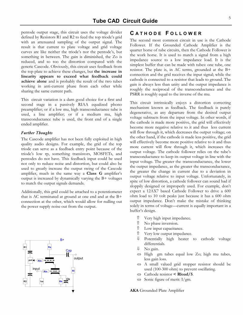
pentode output stage, this circuit uses the voltage divider defined by Resistors R1 and R2 to feed the top triode’s grid with an attenuated sampling of the output signal. The result is that current to plate voltage and grid voltage curves are like neither the triode’s nor the pentode’s, but something in between. The gain is diminished, the Zo is reduced, and so too the distortion compared with the generic Cascode. Obviously, this circuit uses feedback from the top plate to achieve these changes, but the increase in linearity appears to exceed what feedback could achieve alone and is probably the result of the two tubes working in anti-current phase from each other while sharing the same current path.
This circuit variation is a darn good choice for a first and second stage in a passively RIAA equalized phono preamplifier; or if a low mu, high transconductance tube is used, a line amplifier; or if a medium mu, high transconductance tube is used, the front end of a single ended amplifier.
Further Thoughts The Cascode amplifier has not been fully exploited in high quality audio designs. For example, the grid of the top triode can serve as a feedback entry point because of the triode’s low rp, something transistors, MOSFETs, and pentodes do not have. This feedback input could be used not only to reduce noise and distortion, but could also be used to greatly increase the output swing of the Cascode amplifier, much in the same way a Class G amplifier’s output is increased by dynamically varying the B+ voltages to match the output signals demands.
Additionally, this grid could be attached to a potentiometer that is AC terminated at ground at one end and at the B+ connection at the other, which would allow for nulling out the power supply noise out from the output.
C A T H O D E F O L L O W E R The second most common circuit in use is the Cathode Follower. If the Grounded Cathode Amplifier is the quarter horse of tube circuits, then the Cathode Follower is the work horse. It is used to match a signal from a high impedance source to a low impedance load. It is the simplest buffer that can be made with tubes: one tube, one resistor. The plate is, in AC terms, grounded at the B+ connection and the grid receives the input signal; while the cathode is connected to a resistor that leads to ground. The gain is always less than unity and the output impedance is roughly the reciprocal of the transconductance and the PSRR is roughly equal to the inverse of the mu.
This circuit intrinsically enjoys a distortion correcting mechanism known as feedback. The feedback is purely degenerative, as any departure from the desired output voltage subtracts from the input voltage. In other words, if the cathode is made more positive, the grid will effectively become more negative relative to it and thus less current will flow through it, which decreases the output voltage; on the other hand, if the cathode is made less positive, the grid will effectively become more positive relative to it and thus more current will flow through it, which increases the output voltage. The cathode follower relies on the tube’s transconductance to keep its output voltage in line with the input voltage. The greater the transconductance, the lower the output impedance, as the greater the transconductance, the greater the change in current due to a deviation in output voltage relative to input voltage. Unfortunately, in spite of low distortion, a cathode follower can sound bad if sloppily designed or improperly used. For example, don’t expect a 12AX7 based Cathode Follower to drive a 600 ohm load to 10 volt peaks just because it has a 600 ohm output impedance. Don’t make the mistake of thinking solely in terms of voltage—current is equally important in a buffer’s design.
⇑ Very high input impedance. ⇑ No phase inversion. ⇑ Low input capacitance. ⇑ Very low output impedance. ⇓ Potentially high heater to cathode voltage
differentials. ⇓ No gain. ⇔ High gm tubes equal low Zo; high mu tubes,
less gain loss. ⇔ A small valued grid stopper resistor should be
used (100-300 ohm) to prevent oscillating. ⇔ Cathode resistor < Rload/5. ⇔ Sonic figure of merit: I/gm.
AKA Grounded Plate Amplifier
B+
input
output
Cap
R2Ck
Rin
1m Rk
R1
Rl
pot
Rin
Ra

Tube CAD Circuit Guide 6
Textbook Cathode Follower The grid is DC coupled to the preceding stage. The input resistor prevents unwanted oscillations. The cathode resistor and the load resistance in parallel see all the same variation in current flow as the triode. The capacitor blocks the DC voltage at the cathode and passes the AC signal. The larger in value the cathode resistor along with the voltage across it, the better the performance.
Negative PS Cathode Follower The grid is ground level DC coupled at the input. The
output at the cathode must be capacitor coupled as the cathode will be at some voltage higher than ground. As long as the cathode resistor is equal in value, the circuit functions identically to the Textbook Cathode Follower circuit.
Auto-Bias Cathode Follower The reference voltage for the triode’s grid is supplied by the voltage drop that results at the junction of resistors R1 and R2. The advantage of this arrangement lies in that it can be input coupled at a ground reference level (for example, the output of a CD player) and the circuit can still be optimized for good performance by using a large valued cathode resistor. Other than a lower (though still fairly high) input impedance, the circuit functions identically to the Text-book Cathode Follower circuit.
Current Source Loaded Cathode Follower This circuit makes good use of both halves of a dual triode envelope, such as the 6DJ8, 6FQ7, 6SN7, or 12AU7. The bottom triode’s effective plate impedance is greatly magnified by the large valued cathode resistor, the formula: Z = (mu + 1)Rk + rp.
This greatly increased load impedance serves to increase the linearity of the circuit. The biasing of the bottom tube’s grid is performed by the voltage divider made up of resistor R1 and R2. The bypass capacitor across R2 helps to lower the noise of the current source.
Further Thoughts The Cathode Follower has seen a lot of use in audio designs for almost a century. Still, a bit more could be squeezed out of this circuit. For example the cathode resistor could be replaced by a high DCR choke, which would serve as an easy way to bias the tube while still providing for large output voltage swings. Or it could be replaced by a low DCR choke, which would allow for DC coupling of the output, if the grid were connected to a
B+
outCapinput
(Vg)
Rk
Rl
Rin
B+
outCapinput
B-
Rk Rl
Rin
1m
B+
outCap
input
Rk Rl
Rin
1m
R1
R2
B+
outCapinput
(Vg)
.47µf
Rl
Rin
Rk
R1
R2
B+
outCap
input
Rl
Rin
1m
B+
out
inputRin
1m
Cap
B-
High DC resistance choke
Very low DC resistance choke

Tube CAD Circuit Guide 7
C O M M O N C A T H O D E A M P L I F I E R This is a real sleeper of a circuit. Reasons to reexamine this circuit are higher gain and much lower input capacitance than an equivalent Grounded Cathode amplifier, and no phase reversal. Add to this the advantages of low distortion and a high impedance feedback input, and this circuit looks even more appealing. This circuit functions like a Cathode Follower driving the cathode of a Grounded Grid Ampli-fier. The input triode’s plate is, in AC terms, grounded at the B+ connection and its grid receives the input signal, while its cathode is connected to the other triode’s cathode and to a resistor that usually is connected to a negative power supply.
As the input signal swings positive, the cathode follows; thus making the grid voltage of the second triode even more negative relative to its cathode. This change decreases the current flowing through the second triode and its plate load resistor, which defines a smaller voltage across the re-sistor, which, in turn, defines a positive voltage swing at the output; thus no phase inversion. If a positive signal is ap-plied to the grid of the second triode, the cathode follows; thus making the grid voltage of the second triode less nega-tive relative to its cathode. This change results in increasing the current flowing through the second triode and its plate load resistor, which defines a greater voltage across the re-sistor and as the plate load resistor is fixed at the B+ volt-age at one end, so the other end must move down in volt-age to accept the increase in voltage across the resistor; thus phase inversion and a ready high impedance feedback port at the second grid.
The cleanliness of this picture is dirtied by the problem of DC biasing the two grids. Remember, the current flowing through a triode is defined by the cathode to plate voltage and the cathode to grid voltage. If the first triode has a cathode to plate voltage of 300 volts and the second triode, 150 volts, then the first tube’s cathode to grid voltage must be even more negative to lower the current through the triode to match that of the second triode. One solution, although not a desirable one, is to provide two power sup-plies: a 150 VDC for the first triode and a 300 VDC for the second triode. An easier solution is to add an equal valued resistor to the plate of the fist tube, which can be bypassed with a capacitor to the B+ connection or to ground. (Some do not bypass this resistor and lose the advantages of a low capacitance input because of no Miller Effect from the non-voltage swinging plate in the normal common cathode circuit. Additionally, the distortion is greater with the unby-passed resistor configuration.) The first triode’s plate load resistor could be replaced by a zener diode with or without a bypass capacitor.
⇑ Low input capacitance. ⇑ High gain.
⇑ No phase inversion. ⇑ Very linear. ⇓ DC biasing the two grids can be tricky. ⇓ Negative power supply. ⇔ High mu tubes work well. ⇔ Medium output impedance. ⇔ Fair PSRR.
AKA Cathode Coupled Amplifier
Textbook Common Cathode Amplifier Five resistors and a capacitor are all that is needed to make an ex-cellent gain stage with this circuit topology. In fact with the right triode (low mu) and resistor values a nega-tive power supply may not be needed, as the cathode resistor can be routed to ground.
Improved Common Cathode Amplifier The disparity between the needed plate sup-ply voltages in the Textbook Common Cathode Amplifier is eliminated by the in-clusion of a plate re-sistor for the first tri-ode. Because this re-sistor is shunted to ground through the additional capacitor, it sees no AC signal. Consequently, this circuit functions identically to the Textbook Common Cathode Amplifier.
Feedback Common Cathode Amplifier This circuit is identical to the improved version save for the use of two resistors in series for the load resistance and
the feeding back a por-tion of the output sig-nal to the second grid, which is usual ly grounded. The use of feedback results in lower gain, lower dis-tortion, and lower out-put impedance.
B+
input
outCap
B-
Rk Rl
Rin
1m
RaB+2
B+
in out
Cap
B-
Rk Rl
Rin
1m
RaRa
B+
in
outCap
B-
RL
Rk
Rin
1m
RaRa
R1
R2

Tube CAD Circuit Guide 8
D I F F E R E N T I A L A M P L I F I E R Although tube Differential Amplifiers found much use in past electronic gear, they is seldom used in high-end audio, except in the third stage of the Williamson Amplifier and in some balanced designs. Furthermore, with single-ended amplifiers having made such a big splash in audio lately, do not expect the world to go completely balanced any time soon. And balanced is what a Differential Amplifier is all about. It amplifies a balanced signal and largely ignores a single polarity, common-mode signal at its two grids. This can be a wonderful attribute, as noise is usually a single polarity, common-mode phenomenon.
This circuit works by presenting each grid with a signal equal in amplitude, but inverted relative to the other grid. This arrangement results in one triode drawing greater current and the other less current. To the degree that the two triodes are matched, the net effect will be a an unvarying constant current flow through the shared cathode resistor. If the current does not vary through this resistor, nor will the voltage across it, which means that the cathode voltage for both triodes will not vary as well. Thus whatever anti-phase, balanced voltage is presented to both triodes’ grids won’t be mitigated by degeneration at the cathode of each triode, which means more gain—the same amount as a Grounded Cathode Amplifier would yield with the same tube and plate load resistor and with no cathode resistor or a bypassed cathode resistor. On the other hand, an unbalanced signal presented to both grids will result in a change in the current flowing through the cathode resistor, which will cause the cathode voltage to follow the grid voltages, thus greatly reducing the gain at the output. Hence, the name “Differential Amplifier.” This circuit amplifies the differences in grid signals and largely ignores what is common to both grids. The effectiveness of a Differential Amplifier at rejecting common signals to both inputs is denoted by CMRR (Common Mode Rejection Ratio).
⇑ Good PSRR, as the noise cancels out. ⇑ Good balance. ⇑ Similar output impedances. ⇓ Negative power supply.
AKA Balanced Amplifier
Single Polarity and Hum Bucking Common Cathode Amplifier This circuit differs from all the other variations in that it is capacitor coupled and does not need a negative power sup-ply. Additionally, the noise at the output is dynamically re-duced by the injection of countervailing noise at the sec-ond input grid. The voltage divider de-fined by resistors R1 and R2 could be re-placed by a potenti-ometer, allowing for the fine tuning of the hum null.
Further Thoughts The Common Cathode amplifier has not been fully ex-ploited in high quality audio designs. For example, this cir-cuit could be used to build a single-ended amplifier that featured both lower distortion and noise. One problem with this circuit is that when it is used with triodes the issue of just how to apply an equal plate voltage for each triode is solved by the use of a output transformer. The primary winding’s resistance is the only element that would skew the plate voltage potential between the plates and, as this resistance is usually relatively small, the voltage drop across this winding would also be small. The input to the output stage would be from the grid of the tube that meets the output transformer and the noise nulling would be applied at the other grid, as we need to preserve the power supply noise signal phase that the plate connected to the output transformer would see the same amount of noise as the transformer sees at the B+ connection (no delta, no output signal).
B+
inout
Cap
Rk
Rin
1m
RaRa
1mRl
R1
R2
.33µf
B+
input
Rk
Rl
Rin
1m
Rinpot
Common Cathode SE Amplifier
Tube CAD Circuit Guide 9
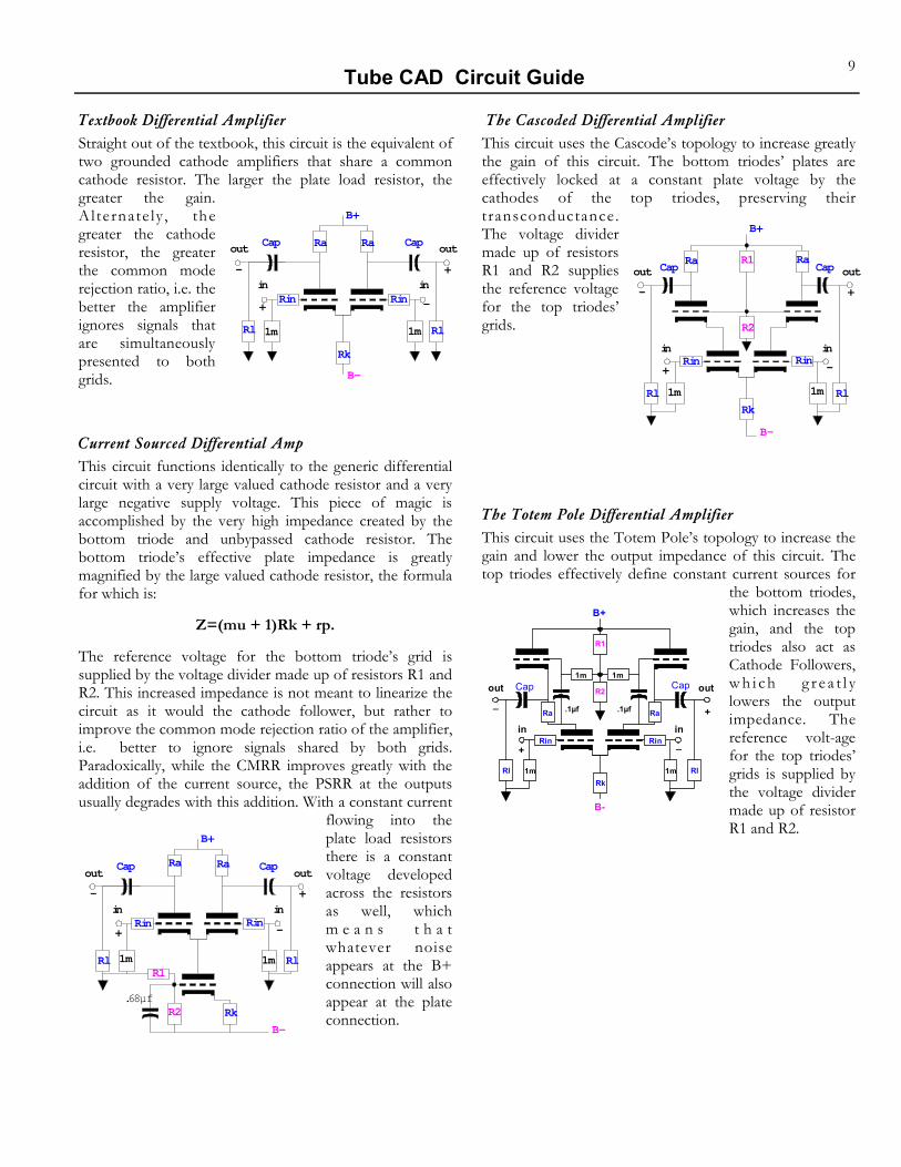
Textbook Differential Amplifier Straight out of the textbook, this circuit is the equivalent of two grounded cathode amplifiers that share a common cathode resistor. The larger the plate load resistor, the greater the gain. Alternate ly , the greater the cathode resistor, the greater the common mode rejection ratio, i.e. the better the amplifier ignores signals that are simultaneously presented to both grids.
Current Sourced Differential Amp This circuit functions identically to the generic differential circuit with a very large valued cathode resistor and a very large negative supply voltage. This piece of magic is accomplished by the very high impedance created by the bottom triode and unbypassed cathode resistor. The bottom triode’s effective plate impedance is greatly magnified by the large valued cathode resistor, the formula for which is:
Z=(mu + 1)Rk + rp.
The reference voltage for the bottom triode’s grid is supplied by the voltage divider made up of resistors R1 and R2. This increased impedance is not meant to linearize the circuit as it would the cathode follower, but rather to improve the common mode rejection ratio of the amplifier, i.e. better to ignore signals shared by both grids. Paradoxically, while the CMRR improves greatly with the addition of the current source, the PSRR at the outputs usually degrades with this addition. With a constant current
flowing into the plate load resistors there is a constant voltage developed across the resistors as well, which m e a n s t h a t whatever noise appears at the B+ connection will also appear at the plate connection.
B+
in
outCapCap
B-
in
out
+
+-
-
Rk
Rin
1m
RaRa
Rl
Rin
1mRl
B+
in
outCapCap
B-
in
out
+
+-
-
.68µfRk
Rin
1m
RaRa
Rl
Rin
1mRl
R2
R1
The Cascoded Differential Amplifier This circuit uses the Cascode’s topology to increase greatly the gain of this circuit. The bottom triodes’ plates are effectively locked at a constant plate voltage by the cathodes of the top triodes, preserving their transconductance. The voltage divider made up of resistors R1 and R2 supplies the reference voltage for the top triodes’ grids.
The Totem Pole Differential Amplifier This circuit uses the Totem Pole’s topology to increase the gain and lower the output impedance of this circuit. The top triodes effectively define constant current sources for
the bottom triodes, which increases the gain, and the top triodes also act as Cathode Followers, w h i ch g r e a t l y lowers the output impedance. The reference volt-age for the top triodes’ grids is supplied by the voltage divider made up of resistor R1 and R2.
B+
in
out
B-
in
out
+
+_
_
.1µf .1µf
Cap Cap
Rk
Rin
1m Rl
Rin
1mRl
RaRa
R1
R2
1m1m
B+
in
outCapCap
B-
in
out
+
+-
-
Rk
1m Rl
Rin
1mRl
RaRa
R2
R1
Rin
Tube CAD Circuit Guide 10
G R O U N D E D C A T H O D E AM P L I F I E R This is the generic tube circuit, comprising 90% of all tube electronics. As the grid sees a varying voltage, the tube’s transconductance defines a varying current across a plate resistor, which develops a varying output voltage. What could be simpler? Yet the amazing aspect of this circuit is that it performs so well that more complex circuits are usually not needed. With just one triode, four resistors and a capacitor, a perfectly usable line stage amplifier can be built. The use of any other single electronic device would require many more supportive parts to achieve equal performance.
What makes the triode a good choice for a single device amplifier is that it will simultaneously exhibit a consistent gain, a fairly low output impedance, and a fairly high PSRR. This is so because, unlike the MOSFET, transistor, pentode, or FET, the triode benefits from having a built-in feedback mechanism in the form of plate resistance: a change in plate voltage will result in a change in current drawn through the triode. While the alternative devices might realize vastly greater gain, the precise amount of gain would vary from sample to sample to a much greater degree than would the triode. Furthermore, the output impedance for these devices is usually so high that it is in effect equal to the impedance of the load resistor. (Each has such an extremely high output impedance that they are close to being constant current sources.) For the same reason, any other device can only yield a much poorer PSRR than a triode based Grounded Cathode Amplifier, once again because of the plate resistance, which will serve to define a bottom resistor of a voltage divider, which divides the noise into a smaller percentage of the total.
⇑ Easily biased. ⇑ Small part count. ⇓ Miller Effect capacitance. ⇓ Gain never exceeds the mu of the tube in use. ⇔ The plate resistor can be replaced with a constant
current source, either tube or solid-state. ⇔ The maximum voltage occurs when (roughly):
Rk = (rp + Rl) / µ. ⇔ If the cathode resistor is bypassed, both the gain
and the distortion will increase, while the output impedance will decrease.
⇔ The cathode resistor could be replaced with a diode or LED or a precision voltage reference IC or even a rechargeable ni-cad battery.
AKA Tube Amplifier
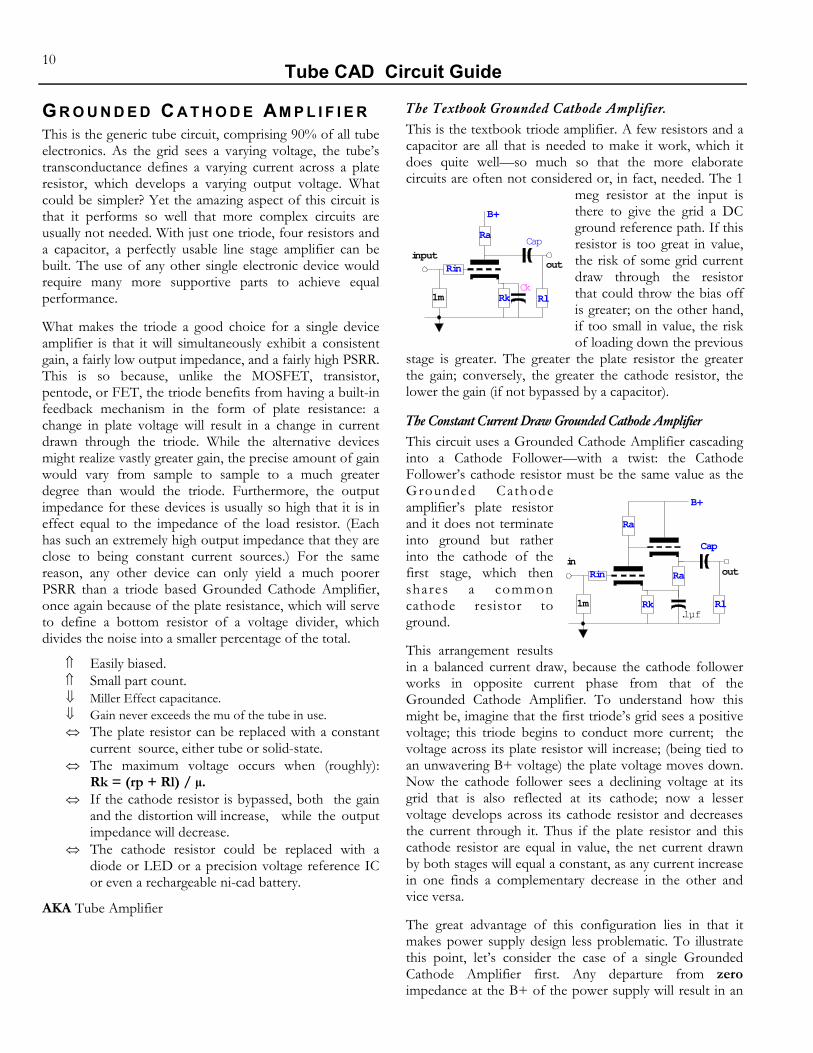
The Textbook Grounded Cathode Amplifier. This is the textbook triode amplifier. A few resistors and a capacitor are all that is needed to make it work, which it does quite well—so much so that the more elaborate circuits are often not considered or, in fact, needed. The 1
meg resistor at the input is there to give the grid a DC ground reference path. If this resistor is too great in value, the risk of some grid current draw through the resistor that could throw the bias off is greater; on the other hand, if too small in value, the risk of loading down the previous
stage is greater. The greater the plate resistor the greater the gain; conversely, the greater the cathode resistor, the lower the gain (if not bypassed by a capacitor).
The Constant Current Draw Grounded Cathode Amplifier This circuit uses a Grounded Cathode Amplifier cascading into a Cathode Follower—with a twist: the Cathode Follower’s cathode resistor must be the same value as the Grounded Cathode amplifier’s plate resistor and it does not terminate into ground but rather into the cathode of the first stage, which then shares a common cathode resistor to ground.
This arrangement results in a balanced current draw, because the cathode follower works in opposite current phase from that of the Grounded Cathode Amplifier. To understand how this might be, imagine that the first triode’s grid sees a positive voltage; this triode begins to conduct more current; the voltage across its plate resistor will increase; (being tied to an unwavering B+ voltage) the plate voltage moves down. Now the cathode follower sees a declining voltage at its grid that is also reflected at its cathode; now a lesser voltage develops across its cathode resistor and decreases the current through it. Thus if the plate resistor and this cathode resistor are equal in value, the net current drawn by both stages will equal a constant, as any current increase in one finds a complementary decrease in the other and vice versa.
The great advantage of this configuration lies in that it makes power supply design less problematic. To illustrate this point, let’s consider the case of a single Grounded Cathode Amplifier first. Any departure from zero impedance at the B+ of the power supply will result in an
B+
inputout
Cap
CkRk Rl
Rin
1m
Ra
B+
inout
Cap
.1µfRl
Rin
1m
Ra
Rk
Ra

Tube CAD Circuit Guide 11
unwanted signal when there is a change in current flowing into it from any and all the stages feeding it. And as the plate resistor and the triode beneath it define a voltage divider, any unwanted signal at the B+ will result in a diminished unwanted signal at the plate. On the other hand, if there is no net current change flowing through the B+ point, then there is no unwanted signal—even if the impedance at the B+ of the power supply is great.
A further advantage of this circuit lies in the reduced need to bypass the first triode’s cathode resistor. Because it should see the net current variation of both triodes, i.e. zero, this resistor comes effectively pre-bypassed. A small cap should be used, just in case of high frequency phase shifts. An additional advantage lies in the higher gain that results from this effectively bypassed shared cathode resistor, as the gain of this circuit is equal to a Grounded Cathode amplifier without a cathode resistor. Additionally, a low output impedance is offered by the cathode follower output stage.
The last advantage lies in the lower distortion that results from feeding identical triodes a complementary signal and current draw, as the deviation from linearity by the first triode is cancelled to a great degree by the symmetrically inverted nonlinear curvature of the second triode. This distortion reducing-effect obtains to the degree that both first and second stages are used symmetrically; dissimilarly valued plate and cathode resistors, or not sharing the common cathode resistor, will break the symmetry and result in greater distortion.
Current Source Loaded Grounded Cathode Amplifier This circuit uses a current source made up of a triode and a large valued cathode resistor. The effective impedance of this configuration is much greater than any plate resistor that could be used with a conventionally low power supply voltage. This results from the very high impedance created by the t o p t r i o d e a n d unbypassed cathode resistor. Its formula is:
Z = (mu + 1)Rk + rp.
For example, a 12AX7 in this configuration—with a total cathode resistance of 50k and only 200 volt power supply and 1 ma current draw—will result in an impedance of: (100 + 1)50,000 + 62,000 = 5,112,000 which, if it were replaced by an equivalently valued resistor, would need a power supply voltage of at least 5,262 volts in order to experience a
B+
input
outCap
.1µf
CkRk Rl
Rin
1m
Ra
1m Rk
current flow of 1 ma. The benefits that derive from this arrangement are a greater gain, a much improved PSRR, and a lower distortion figure.
The Inverted Transformer Coupled Grounded Cathode Amplifier This amplifier circuit may seem strange at first, but if examined closely, it can be seen that it functions in the same way as the generic Grounded Cathode Amplifier: a positive signal at the grid drives the triode into greater conduction, which leads to a greater current flow through resistor Ra, which in turn defines a greater voltage to be developed across it. But as Ra is con-nected to ground and not B+, the voltage swings higher rather than lower, which means that there is no phase inversion.
Further Thoughts Can anything new be done with the Grounded Cathode amplifier? Probably, yes. One place to start might be the use of nonlinear loads. The triode itself is not perfectly linear; consequently loading it with a countervailing non-linearity just might yield linearity. The “triode region” of a FET might be useful in the biasing of a tube current source to load the plate of the bottom triode. (Or maybe the filament of a small light bulb.) Experimentation is needed.
B+
outCap
input
Rl
Rin
1mRk
Ra
1m
1:1
Ck
Tube CAD Circuit Guide 12
G R O U N D E D G R I D Although this is one of the three basic tube amplifier circuits, the Grounded Grid is seldom used in audio equipment because of its very low input resistance. It offers slightly greater gain than the Grounded Cathode Amplifier, a much lower input capacitance, a zero phase reversal of the signal—all of which makes the Grounded Grid something of a sleeper circuit, if you can live with the low input impedance.
It works by receiving the input signal voltage at the cathode rather than the grid, which is grounded in this circuit. As with the Grounded Cathode Amplifier, the varying voltage between the fixed voltage grid and the varying voltage cathode work on the tube’s transconductance, which defines a varying current across a plate resistor, which in turn develops a varying output voltage. Because an increase in cathode voltage decreases the current flowing through the triode, the plate resistor (which is in the same current path) sees both less current flowing through it and less voltage developing across it; thus the plate voltage swings toward the fixed B+ voltage and there is no phase inversion.
The use of the cathode as the input results in an input impedance that is very low indeed: roughly, (rp + Ra)/(mu + 1). The main advantage of this arrangement lies in the shielding of the cathode from the plate voltage swings by the grounded grid, which means that the Miller Effect capacitance does not obtain.
Furthermore, the gain is slightly greater than that of a complementarily laid out Grounded Cathode circuit. This gain increase results from the fact that the cathode is further from the plate than the grid is to the plate, which gives the cathode an electrical “longer lever” advantage in controlling the variation of current flow through the circuit than the grid:
(mu + 1)Ra/(Ra + rp)
vs.
muRa /(Ra + rp) for the Grounded Cathode Amplifier.
Perhaps this circuit might make a good choice for the input stage of a CD I to V stage or an MC phono pre-preamp, as its low input impedance would prove to be an asset in these applications.
⇑ Very low input impedance. ⇑ No phase inversion. ⇓ Very low input impedance. ⇓ Input coupling capacitor.
AKA Non-Inverting Amplifier
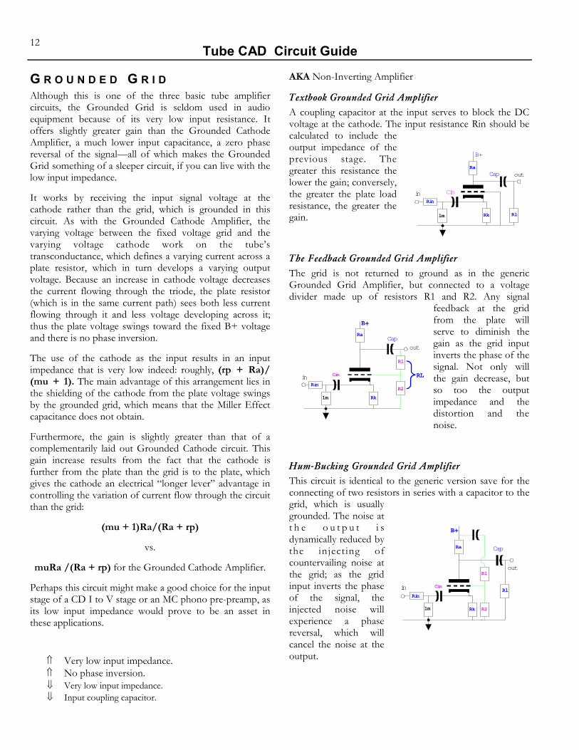
Textbook Grounded Grid Amplifier A coupling capacitor at the input serves to block the DC voltage at the cathode. The input resistance Rin should be calculated to include the output impedance of the previous stage. The greater this resistance the lower the gain; conversely, the greater the plate load resistance, the greater the gain.
The Feedback Grounded Grid Amplifier The grid is not returned to ground as in the generic Grounded Grid Amplifier, but connected to a voltage divider made up of resistors R1 and R2. Any signal
feedback at the grid from the plate will serve to diminish the gain as the grid input inverts the phase of the signal. Not only will the gain decrease, but so too the output impedance and the distortion and the noise.
Hum-Bucking Grounded Grid Amplifier This circuit is identical to the generic version save for the connecting of two resistors in series with a capacitor to the grid, which is usually grounded. The noise at t h e o u t p u t i s dynamically reduced by the injecting of countervailing noise at the grid; as the grid input inverts the phase of the signal, the injected noise will experience a phase reversal, which will cancel the noise at the output.
B+
in
outCap
Rk Rl
Rin
1m
Ra
Cin
B+
in
out
Cap
Rk
Rin
1m
Ra
R1
R2
RLCin
B+
in
out
Cap
Rk
Rin
Ra
R1
R21m
RlCin

Tube CAD Circuit Guide 13
The Dual Polarity PS Hybrid Grounded Grid This circuit makes use of dissimilar technologies: the tube is a depletion mode device, its grid must be made very negative to stop conducting current altogether and the P-channel MOSFET is an enhancement mode device, its gate must be charged to a greater negative voltage than its source in order for it to conduct at all. In this circuit, this means that the zero DC reference voltage at the gate will result in its source being at some positive voltage relative to ground, which will serve to help bias the triode, since its grid must be at a voltage less than its cathode. Therefore, the cathode resistor Rk may not be needed, if the right MOSFET is chosen.
This circuit might make for a great line stage amplifier, as it would exhibit wide bandwidth, no phase reversal, and a fairly low output impedance. Feedback, as implemented in Hum-Bucking Grounded Grid Amplifier, could be applied easily and would yield the same benefits. Icing on this cake might be the inclusion of a Cathode Follower with a cathode resistor equal in value to that of the plate resistor, which would deliver the advantages of a constant current draw as displayed in variation B of the Grounded Cathode Amplifier. The negative power supply need not be of any great value as the MOSFET needs only a few volts to function; 6.3 VDC would do and could serve to feed the heaters as well.
Further Thoughts The Grounded Grid amplifier should be used more often in audio designs. For example, this circuit could be used to build an intriguing MC phono cartridge head-amp or pre-preamplifier. Something close to universal agreement exists on the topic of the desirability of a good step-up transformer to couple the MC cartridge to the rest of the audio chain. Usually the output of these transformers is connected to the grid, but connecting it to the cathode of a Grounded Grid amplifier might be more beneficial, as an MC cartridge needs to see a low input impedance, which the cathode easily affords.
Another thought is that the Grounded Grid Amplifier could be used as the output stage of a single ended amplifier. The cathode could be driven by a P-channel
B+
outCap
input
Rk Rl
1m
Ra
Rin
B-
MOSFET’s source, while the grid was grounded. Using a triode like the 6C33 would necessitate a grid-to-cathode voltage differential of about 100 volts to bias the tube correctly. Now if plate voltage of the driver tube was 100 volts, then the gate of the MOSFET could be DC coupled to the plate; the drain would be connected to ground. Normally, DC coupling is a scary prospect in tube circuits, as the voltages are high and the devices require time to warm up (furthermore, the devices are removable; pull a tube out of its socket in a DC coupled amplifier that is running, and you can expect to see large sparks). In this configuration, however, if the driver tube fails or is removed, the plate load resistor will pull the gate and source voltages high, which will turn off the output tube, as its grid will be too negative relative to its cathode to allow the tube to conduct. Additionally, the grid could never be driven positively relative to the cathode because the MOSFET’s source in this setup can never move below ground potential.
B+
input
Ra
Rin
Rk
output
1m
360vdc
100vdc
0vdc

Tube CAD Circuit Guide 14
I - T O - V C O N V E R T E R Unlike all the other circuit types, the I-to-V circuit variations are not based on one seed circuit, but rather four different circuits that attempt to perform the same function—namely the conversion of a current variation into a voltage variation. Because the tube is a voltage driven device, it does not easily lend itself to converting current into voltage (as would a transistor, which is a current driven device). Still, a surprisingly good I-to-V converter can be made from the following tube circuits.
The key point here is that a good I-to-V converter circuit should offer a zero input impedance, one that does not vary in voltage, and should realize a full conversion into output voltage of all the current variation fed across Riv, the reference resistor. A near zero impedance input is necessary for many digital to analog converters (DAC), as often these suffer from a non-symmetrical slewing ability when presented with a high input resistance due to the circuit topology internal to the DAC; in fact, some DAC’s fail to function at all if their output sees any departure greater than .3 volts from the ideal input of 0 volts.
Generic I-to-V This is basically the same circuit as the Grounded Cathode Amplifier. The main difference lies in the low value of the grid resistor, Riv (10 ohms, for example). This resistance defines both the input impedance and a voltage source for the input of the amplifier. A 1 ma input current into this resistance will develop a small voltage (0.01 volts across 10 ohms), which will be amplified by the output at the plate. The precise value of resistor Riv will involve some adjustment, as the current source might be affected by the nonzero input resistance and the gain realized by the amplifier will vary with different load impedances.
⇑ Simple to execute. ⇓ High input impedance. ⇓ No feedback that would lower noise and
distortion and aging effects. ⇔ The Cascode or Totem Pole Amplifiers could just
as easily be used.
Improved I-to-V Converter This circuit uses a Grounded Grid Amplifier cascaded into a Grounded Cathode Amplifier. The low input impedance of the first stage greatly assists in keeping the input impedance to this I-to-V Converter very low. The gain from this stage multiplied by that of the second stage defines the amount of feedback this circuit enjoys, as the output is connected to the input through resistor Riv. The feedback further reduces the input impedance of this circuit and greatly reduces the distortion and noise at the output.
Resistors R1 and R2 are specified to yield the correct voltage drop to meet the negative supply voltage and to eliminate noise at the output. This noise reduction is achieved through a very non-intuitive approach: the low value of resistor R1 is chosen to interject noise at the plate from the negative power supply connection. If enough noise signal, which is in anti-phase to the positive power supply noise, is superimposed on the positive power supply noise, then the noise at the top triode’s plate will equal that of the negative supply rail; which means that the bottom triode’s grid will see none of the negative supply noise, as if its grid were tied to the negative supply rail. Still the bottom triode and its plate resistor define an AC voltage divider. Unless the AC voltage division between these two equals the ratio between B+ and B- voltages, there will be power supply noise at the output. (Usually, adding a bypass capacitor across the a tube’s cathode resistor will make for less noise; here it will make for more noise, as it moves the division point towards the negative supply and away from the midpoint near ground.)
⇑ Very low input impedance. ⇑ Very low noise. ⇓ Negative power supply. ⇓ Dissimilar positive and negative voltages. ⇓ High cathode to heater voltages. ⇔ Resistor R1 could be replaced by a potentiometer. ⇔ This circuit would make a good choice for a CD
I-to-V stage.
B+
in
outputCap
Rk
Rl
Ra
RivCk
B+
inoutCap
B-
0vdc
Rl
Rk
R1
Riv
Ra2
Ra
1m
Vbias
+R2

Tube CAD Circuit Guide 15
Lohoff I-to-V Converter This is basically the same circuit as the White Cathode Follower, but with the addition of an I-to-V resistor between the top cathode and the bottom plate—a brilliant move in that it borrows the one great virtue of the White Cathode Follower: a very low output impedance, which in this circuit becomes the input impedance. This very
desirable attribute in an I-to-V converter results from two sources. The first is t h e C a t h o d e Follower action of the top triode. The second is the feedback to the bottom tube’s grid from the voltage developed by the current flow through the top tube’s plate load resistor.
To understand how this circuit works, imagine that a current source were attached from the B+ connection to the input of this circuit; the result would be an increase in current flowing through the I-to-V resistor (Riv), which would develop into a downward voltage swing. Conversely, if a current source were attached from the B- connection to the input of this circuit, the increase in current flowing through the top triode and its plate load resistor would develop into a downward voltage swing into the grid of the bottom triode, which would serve to decrease the current through the bottom triode and the I-to-V resistor and define an upward voltage swing at the output.
⇑ Very low input impedance. ⇑ Single current path. ⇑ Push-Pull operation. ⇓ Negative power supply. ⇓ High cathode to heater voltages. ⇔ Sonic figure of merit: current/gm. ⇔ High transconductance tubes work well. ⇔ This circuit would make a good choice for a CD
I-to-V stage.
Single Polarity Power Supply I-to-V Converter This circuit, like the generic one, does not require a dual polarity power supply, which in some applications can be decisive. It is made up of a Grounded Grid Amplifier cascading into a Grounded Cathode Amplifier. The input must be capacitor coupled, as the cathode is a few volts away from ground. Unfortunately, this capacitor must be very large in value so as not to have its reactance interfere with the circuit’s performance. The output requires a coupling capacitor as well and it too must be fairly large compared to the usual tube circuit coupling capacitor, as it
is loaded down by the Riv resistor.
As this circuit does not enjoy the PSRR tricks that the Improved I-to-V Converter does, the use of a regulated power supply might be required.
⇑ Very low input impedance. ⇑ Very low output impedance. ⇑ Single polarity power supply. ⇓ Very large capacitor values. ⇔ Sonic figure of merit: current/gm. ⇔ High transconductance tubes work well. ⇔ This circuit would make a good choice for a CD
I-to-V stage.
B+
C2 Rk
Ra
Rk
Ra
1m
outin
Riv
Ck
.1µf
Cap
Rl
B+
input
outCap
B-
.1µf
Vbias0vdc
Ck
Riv
Rl
1m
Ra
Rk
Rk

Tube CAD Circuit Guide 16
L O N G T A I L P H A S E S P L I T T E R This is the second stage in many power amplifiers. It boasts the advantage of providing both phase splitting and voltage gain. It works very much like a Differential Amplifier with one grid used as an input and the other grounded. Does this unbalanced operation result in an unbalance at the output? Yes—quite a bit, actually. With a low mu triode, such as the 6BX7, the imbalance can be high as 20% in a typical circuit arrangement. To the extent that the shared cathode resistor approaches infinity, the unbalance approaches 1/mu. Using unbalanced plate load resistors, however, can restore the balance at the circuit’s output.
In most amplifiers the input signal is not the only signal present. Noise that might have been largely ignored by the Differential Amplifier is amplified in this circuit, as noise at the input grid is not met with a countervailing noise at the second grid. Thus, quite paradoxically, PSRR can be improved by introducing some power supply noise into the second grid, as this will rebalance the amplifier in terms of noise. This trick requires a second capacitor connected from the second grid to the B+ noise source and a capacitor connect to the second grid to ground (Long Tail with Hum-Bucking). By varying the ratio between these two capacitors, the amount of noise can be made to match that entering the input from the preceding stage.
⇑ Good PSRR, as much of the common mode noise cancels out in the output stage.
⇑ Good voltage swing. ⇑ Fair balance. ⇑ Has gain. ⇑ Similar output impedances. ⇓ Must be tweaked for best performance. ⇔ A medium mu tube works well here.
AKA Cathode Coupled Phase Splitter.
Textbook Long Tail This circuit works much like a Differential Amplifier which has one input grounded. Input signals are reflected by half at the common cathodes, which gives this circuit roughly half the gain of a D i f f e r e n t i a l Ampl i f i e r . The degree that the signal
is not halved is the degree that the outputs will be unbalanced. Balance in gain between the two phase legs can be restored by juggling the value of the Ra2 resistor.
Long Tail with a Current Source The bigger Rk is, the better the AC balance between the two phase legs. The cathode resistor Rk is here replaced by a tube-based current source. This circuit uses a current source made up of a triode and a large valued cathode resistor. The effective impedance of this configuration is much greater than any cathode resistor that could be used with a conventionally low power supply voltage. This results from the very high impedance created by the bottom triode and its unbypassed cathode resistor, the formula for which is: Z = (mu + 1)Rk + rp. For example, a 12AX7 in this configuration—with a cathode resistor of 50k and only a 200 volt power supply and a 1 mA current draw—will result in an impedance of: (100 + 1)50,000 + 62,000 = 5,112,000. If this current source were to be replaced by a 5,112,000 resistor with a current flow of 1 mA, a negative power supply voltage of at least 5,262 volts would be needed
Long Tail with Only a Positive PS This is the more usual biasing method for the Long Tail Phase Splitter. Because it allows for DC coupling of the input to the preceding stage, it is often used as the phase splitter in p u s h p u l l amplifiers. In AC terms, this circuit f u n c t i o n s identically with the T e x t b o o k variation.
B+
in
outCapCap
B-
out
+
+-
Rk
Rin
1m
Ra2Ra
RlRl
B+
in
outCapCap
B-
out
+
+-
Rk
Rin
1m
Ra2Ra
RlRl
R2
R1
B+
in
outCapCapout
+-
Rk
Rin
Ra2Ra
RlRl
1m
Vref

Tube CAD Circuit Guide 17
Long Tail with Hum-Bucking Restoring balance is the point behind this circuit design. In a balanced configuration, noise which is common to both phase legs is largely rejected by the nature of a balanced amplifier design. In the Textbook variation, the noise is not balanced at both grids, which unbalances the circuit; whereas here both grids see the same amount of power supply noise. Capacitors C1 and C2 serve as a voltage divider to the power supply noise. If the noise at the plates of this circuit are both in phase with each other and equal in amplitude, it will cancel out in the output transformer.
P L A T E F O L L O W E R This circuit is used in place of a Cathode Follower. Like a Cathode Follower, it boasts a low output impedance, wide bandwidth, and low distortion. Unlike a Cathode Follower, it does invert the phase at its output and it can have a gain of (or greater than) unity. One of its key advantages is that the cathode potential is close to ground, thus making the heater-to-cathode voltage limit less of an issue.
The Plate Follower is made up of a Grounded Cathode Amplifier with two extra resistors: a feedback resistor tied from the output to the grid and a resistor bridging the grid to the input. Basically, the ratio between these two resistors defines the gain of this circuit. Of course, the open loop gain sets the upper limit to the possible gain. But at the other extreme, the lower limit to gain is nearly nothing, as the ratio between these two resistors can be skewed severely. This flexibility of gain adjustment is the main advantage to this circuit over any other tube follower circuit.
⇑ Easily biased. ⇑ Adjustable gain. ⇑ Low cathode to heater voltage differential. ⇓ Phase inversion. ⇓ An extra coupling cap in the middle of the
circuit. ⇓ Much lower input impedance than a cathode
Follower. ⇔ Gain never exceeds the mu of the tube in use. ⇔ The plate resistor can be replaced with a constant
current source, either tube or solid-state. ⇔ The maximum voltage occurs when the cathode
resistor is not bypassed and (roughly): Rk = (rp + Ra)/µ.
⇔ If the cathode resistor is bypassed, both the gain and the distortion increase while the Zo de- creases.
⇔ A good choice for a simple line stage amplifier.
AKA Anode Follower.
Textbook Plate Follower This circuit is textbook, entirely textbook, and relies on the input connecting to a low impedance output from the prior stage. Other than the choice of having the cathode resistor bypassed or not bypassed, there are not a lot of options. One possibility would be to replace the plate resistor with a FET fixed current source.
B+
input
outCap
CkRk Rl
R1
1m
Ra
R2
B+
input
outCap
out
+- C1
C2Vref
Rk
Rin
Ra2Ra
RlRl
1m
Cap
Where PSRR = PSRR of preceding stage
PSRR

Tube CAD Circuit Guide 18
Compound Amplifier and Plate Follower Here a Grounded Cathode Amplifier is cascaded into a Textbook Plate Follower.
The upper limit to the potential gain of this circuit is the open loop gain of the two stages times each other, which can be a truly large amount with the right triodes. The lower limit to gain is set by the gain of the first stage. If the second stage’s gain is set unity, then the net current draw for the circuit will remain constant in spite of huge voltage swings at the output as the two stages work in anti-voltage phase and in current phase to each other.
Current Sourced Plate Follower The plate load resistor in this circuit has been replaced by a tube current source. With a Grounded Cathode Amplifier (the core of the Plate Follower), the larger the plate load resistance, the closer the gain approaches the mu of the triode, the greater the PSRR, and the lower the distortion. The current source is a circuit that approximates a superbly large plate load resistor. For example, a 12AX7 based current source made up of a 100k cathode resistor, yields an effective impedance of over 10 meg. An equivalent resistor would require a power supply of at least 10 kilovolts to allow a current draw of 1 mA, whereas the 12AX7 current source would require only 200 volts to establish the same 1 mA current draw.
Transformer Coupled Plate Follower The addition of a transformer converts the plate follower into a much closer mirror image of the Cathode Follower. A 1:1 isolation transformer allows for the 100% degeneration of the C a t h o d e F o l l o w e r , consequently the gain
B+
input
outCap
CkRl
Rin
1m
Ra
1m
Ra
R1 R2
Rk
B+
input
outCap
.1µf
CkRk Rl1m
Ra
1m Rk
R1 R2
remains fixed at somewhat less than unity. In fact, other than the phase reversal, these two circuits are electrically very close in terms of PSRR, Zo, gain, bandwidth, and distortion.
Further Thoughts The Plate Follower should be used more often in audio designs. The Cathode Follower does not work as well one imagines it should; whereas the Plate Follower works better than one might suppose.
The Compound Amplifier and Plate Follower circuit could find use as a gain block in a two stage passive equalization phono preamp. The ceiling of 100 for the mu of most audio type triodes can be overcome by setting the gain of the Plate Follower half of this circuit to 5, which would increase a 6DJ8’s effective mu to 150.
Line stages usually have far too much gain. An optimal amount of gain might be 3, which could be realized by using a 6SN7 in the Compound Amplifier and Plate Follower circuit with the Plate Follower’s gain set to .2 times its input.
input
B+
outCap
Rin 2m
Rk
Rl
Ra
2mCk
1:1

Tube CAD Circuit Guide 19
P U S H P U L L A M P L I F I E R Clive Bell began his book on art by stating, “It is improbable that more nonsense has been written about aesthetics than anything else: the literature of the subject is not large enough for that.” It is tempted to say the same about what has been written concerning the Push Pull Amplifier, particularly the Cathode Follower Circular Push Pull variation. Truly staggering heights of silliness have been achieved in describing how this circuit constitutes ipso facto a Class A amplifier no matter how little quiescent current it draws; how it is some radical departure from all previous amplifiers.
The humbling truth is that it is not fundamentally that different from the standard output stages in many cheap transistor receivers, as two power supplies in tandem are electrically not that different from two power supplies hooked up in totem pole fashion. It does not run exclusively in Class A, as one of the tubes can be completely turned off over a large portion of the output voltage swing.
This is not to say that this a bad amplifier design; it isn’t. The Cathode Follower Circular Push Pull allows for easier fixed biasing of the output tubes, if nothing else. Still it is not something that belongs in an X-File.
(The best explication of this circuit is to be found in Zimmermann and Mason’s Electronic Circuit Theory: Devices, Models, and Circuits. John Wiley & Sons, Inc., 1959. Chapter 11, section 5, “A Balanced Power Amplifier with Direct-Coupled Load.”)
⇑ Can source as well as sink current, i.e., push pull operation.
⇑ Phase is user definable with transformer input. ⇓ Requires an expensive input transformer. ⇔ Does not have to be used solely as a power
amplifier output stage.
AKA Balanced, Circlotron, Parallel Amplifier.
Text Book Push Pull Amplifier The first notable feature of this circuit is that it contains an input transformer. This is not the only way the amplifier could be ar-ranged, but it is the best for showing the signal being superimposed across the cathode to grid potential. For this circuit to work as in-tended, each grid must see the
same amplitude of input signal. The transformer’s connection at the top triode’s cathode and grid ensures that the cathode to grid signal voltage will be equal in amplitude to the bottom triode’s. The second notable feature is the absence of a plate resistor. In many ways the load resistance is the plate resistor, even if it is to be found at the cathode of the top triode. In fact the gain is identical to that of a Grounded Cathode Amplifier with the same triode and with a plate load resistor twice the value of the load resistance.
Grounded Cathode Circular Push Pull Now for a lesson in perspective: this circuit is functionally the same as the Textbook example except that this one is directly coupled. The fact that the two power supplies are cross-coupled to each other does not make the circuit behave any differently in AC terms. The tubes could have just as easily been biased by a fixed negative power supply voltage and the ground could have been placed on the other output point or even at some midpoint between these two.
Cathode Follower Push Pull Here gain has been swapped for low output impedance and low distortion, which is the same trade made when going from a Grounded Cathode Amplifier to a Cathode Follower. If the transformer’s connections to the triode’s grids are viewed carefully, you can see that any forcing of the output either up or down in voltage will force an increase or decrease in the cathode to grid voltages of the triodes and will cause a greater and lesser current flow through the triodes that will tend to buck that change in voltage at the output. Much like the missing plate resistor from the Textbook variation, the load resistance is the cathode resistor in this circuit. The gain and Zo of this circuit are equal to that of a Cathode Follower with a cathode resistor twice as large in value as the load resistance in this circuit.
B+
input
output
+
-
B+
+PS
-Rin
PS
Rin
Rl
Rk Rk
2m 2m
CkCk +
B+
outCapinput
Rl
Rin
Rk
Rin
Rk2m
Ck
Ck
2m
.1µf1:1
.1µf
B+
outCapinput
Rl
Rin
Rk
Rin
Rk
2m
2m
Ck
Ck
1:1

Tube CAD Circuit Guide 20
Cathode Follower Circular Push Pull Once again, this circuit is the functional equivalent to that of prior example. It differs in that there is no coupling capacitor, but the gain and Zo remain the s a m e . A l t h o u g h cathode bias is used here, fixed bias could just as easily be used by referencing to a negative power supply voltage. Where the ground attachment is made is flexible in this design; it can be placed at either output point or at the midpoint between the two.
To understand better what goes on in this amplifier, take two low voltage batteries and three equal valued resistors. Place the batteries where the power supplies are in this circuit and replace each triode with one resistor. Place the third resistor where the load would attach in this circuit. Now measure the voltages throughout the circuit. After this, replace one of the triode replacement resistors with a value twice as great and the other with a resistor half as large. Measure the voltage throughout the circuit again.
B+
input
+
-
B+
+PS-
Rin
PS
Rin
RL
Rk RkCkCk
2m2m
+ -output
1:1
Conclusion An analysis of the foregoing circuits forces the conclusion that the Circlotron type circuits are not radically different from the stacked series style, as there is little AC performance difference between them. Yet one aspect of AC performance differs greatly: PSRR. In the stacked examples, the power supply noise is voltage divided by the two triodes’ plate resistances from B+ to ground. But in the Circlotron arrangement, the power supply noise is greatly cancelled by the parallel placement of the power supplies—if each PS’s noise is equal in amplitude and in phase with one another, it tends to cancel at the output (this true only if the tubes are both run in Class A). The stacked Push Pull, however, can also achieve a similar reduction in noise at the output by using a dual polarity power supply arranged so that the single B+ voltage is split into a B+ and a B- rail, with the output at ground potential. In this case, the power supply noise will be in anti-phase between positive and negative legs, which means the equal voltage division between tubes results in null of the power supply noise at the output, as the noises cancel at the mid point (+1 + -1 = 0). In actual practice, this rosy scenario begins to vanish with the departure from strict Class A to Class AB operation of the output stage in either Push Pull Amplifier type.
1k 4k
2k
+ +
Now swap the tube replacement resistors and measure again. The results are representative of what goes on in this amplifier when one triode begins to conduct more as the other conducts less.
2k 2k
2k
+ +
+140vdv
-140vdv
+280vdv
0vdv
Noise =
Noise =
Push-Pull Amplifier with a power supply rejection ratio of one half.
Push-Pull Amplifier with a power supply rejection ratio of nearly 100% of the noise.

Tube CAD Circuit Guide 21
S P L I T L O A D P H A S E S P L I T T E R Although much maligned, this phase splitter actually sets the standard for balance. As long as the plate resistor equals the cathode resistor, balance is pretty much assured. Nonetheless, this circuit is criticized for not having any gain, clipping sooner than the alternatives, and having dissimilar output impedances on each phase leg.
The first objection is certainly true, but then gain is not always necessary and can be a liability in an amplifier without feedback. The second objection is equally true, as this circuit can swing only half the voltage of a Long Tail Phase Splitter. This is so because the triode sees both phase’s voltage swing, one at its cathode and one at its plate; whereas the Long Tail Phase Splitter’s triodes see only one phase voltage swing at their plate. Still, maximum voltage swing is not always a necessity; particularly if this circuit were to be used as the very first stage in a power amplifier, which is in many ways the best place to use it, as its low distortion and excellent balance would well serve the remaining balanced portions of the amplifier. The last criticism seems the most damning, as a large discrepancy in output impedances can only prove disadvantageous. Or must it?
The answer, in the case of this circuit, is that as long as each phase leg of this circuit is equally loaded both resistively and capacitively, the discrepancy in output impedances does not in practice make that much difference. This paradox can be resolved when we compare what happens in two cases. In the first case. we load the positive phase leg (the cathode output) with increased capacitance—the circuit now begins to resemble a Grounded Cathode Amplifier with a bypass capacitor across its cathode resistor, i.e. its high frequency response at its plate is increased. In the second case, we load the inverting leg (the plate output) with a increased capacitance—the circuit now begins to resemble a Cathode Follower, i.e. its high frequency response at its cathode is increased, as the capacitance across its plate makes the plate voltage fixed at high frequencies. A wash of sorts occurs where both phase legs share the same frequency response with a balanced capacitance loading of cathode and plate outputs.
Does this mean that the circuit can work into any low impedance and/or high capacitance load just because both phase legs are equally loaded? Of course not. Capacitance must be charged with current to force the voltage swings we need, which means that if the current is sufficient to charge the equal load capacitance at the slew rate needed to insure a certain bandwidth at a certain peak output voltage, this circuit should work just fine.
⇑ The best balance of all phase splitters. ⇑ Simple and requires no tweaking. ⇓ Dissimilar output impedance and PSRR figures
at each phase leg. ⇔ Should be used as early on as possible in a
amplifier. ⇔ High mu tubes suffer the least gain loss.
AKA Cathodyne Phase Splitter, Concertina.
Textbook Split Load Phase Splitter There is not much going on here—just a triode, a f ew res i s to rs and capacitors. The plate resistor and cathode resistor share the same c u r r e n t p a t h , consequently balance is easy to achieve between phase legs.
Cap Coupled Split Load Phase Splitter The advantage this variation enjoys over the previous one lies in the elimination of the need to couple the input at a high voltage, as the voltage divider, defined by
resistors R1 and R2, biases the triode at the right DC voltage value.
Equal Zo Split Load Phase Splitter This circuit uses a Grounded Cathode Amplifier cascading into a Cathode Follower—with a twist: the first triode’s cathode is the non-inverting output. And the inverting leg’s output is found at the cathode of the second triode.
B+
inout-Cap
out+
Vref Rk Rl
Rin
Ra
Rl
B+
in
out-Cap
out+Cap
Rl
Ra
Rl
R1
R21m Rk
Rin
out-
out+
B+
inRin
R1
Rk
R2
Rl
Cap
Cap
Vg
Rl
R3
Ra

Tube CAD Circuit Guide 22
This arrangement results in a balanced output impedance, as the ratio between resistors R1, R2, and R3 equalizes the output impedances. Unequal load capacitance will unbalance this circuit.
Current Sourced Split Load Phase Splitter This circuit uses a tube based constant current source to load and shield the triode’s plate. The juggling of the Rl2 resistor value will restore the balance that results from an equal load. The end result of these increased efforts is an improved PSRR (something very valuable in a pre-amp).
Further Thoughts The Split Load Phase Splitter is a much better circuit than most imagine. Its reputation suffers from decades of misuse, but if its operation is understood fully, one comes to think of it as being one of the useful circuits. For example it helps eliminate power supply noise in dual-polarity power supply push-pull amplifiers. The two tubes that make up the output stage work as a voltage divider for the power supply noise. If both tubes are the same type, the division is one-half. One-half of +1 and –1 is 0, which means that as long as the anti-phase relationship and amplitude of positive and negative power supply rails match, the output noise from these sources will equal zero. The top tube’s cathode and grid see the same signal at idle; therefore, the bottom tube’s cathode and grid must see the same signal, if this circuit is to balance. This means the bottom tube’s grid must see all of the negative supply rail’s noise. Here is where the Split-Load Phase Splitter comes in to play. This phase splitter has a great PSRR figure relative to its cathode and a very poor to non-existent one at its p l a t e . T h i s discrepancy can be used to drive the top tube from the cathode connection of the Split-Load and the bottom tube from its plate connection.
S R P P / T O T E M P O L E A M P L I F I E R This circuit is very popular. What the Cascode was to the 80’s the Totem Pole is to the 90’s. This compound amplifier works by using the top triode as both a cathode follower and a current source for the triode below it. The positives: high gain, good PSRR, low Zo, one current path. The negatives: high cathode to heater voltages, phase inversion.
Not much resistance is needed in between the top tube’s cathode and the bottom tube’s plate to yield a final gain that closely approaches the mu of the bottom tube, as this resistance will be effectively multiplied by the mu of the top tube plus one and then added to the top tube’s plate resistance:
(mu + 1)Ra + rp.
For example, a 6DJ8 based Totem Pole circuit with an Ra resistor of 2k will effectively load the bottom triode with a load of 71k, i.e. (33 + 1)2,000 + 3,000 = 71,000. This high effective plate load resistance also serves to buffer the bottom plate from the noise at the B+ connection, thus improving the PSRR figure of the circuit. The top tube’s cathode provides the low output impedance of the circuit, as all the benefits of using a Cathode Follower obtain as the top tube defines a Cathode Follower. Furthermore, the top tube works even better than a Cathode Follower: it is aided in driving the load resistance by the bottom tube, which works in an opposite current phase to the top tube, but the same voltage phase. In other words, when the top tube conducts less as its input voltage swings negative, the bottom tube conducts more, which pulls its plate voltage down; and when the bottom tube conducts less, its plate voltage rises, which causes the top tube to conduct more current. This push-pull action not only helps to drive the load resistance, but also serves to decrease the distortion of the circuit by averaging out the transfer curves of the top and bottom tubes, thus increasing the linearity the net transfer curve for the circuit.
⇑ Very low output impedance. ⇑ Low distortion. ⇑ Good PSRR. ⇑ Single current path. ⇑ Push Pull operation. ⇓ Fairly complex. ⇓ Internal coupling capacitors. ⇓ High heater to cathode voltage differentials. ⇔ Should be used in a high current
operation. AKA SEPP, Cathode Follower Cascode
B+
input
out -Cap2
.1µf
Rk
Rl2
Rin
1m
Ra
1m Rk2
Rin
Rl
out +Cap
B+
outinput
R a
R lR k
1m
B-
200v
100v
-100v
100v
300v
R
Tube CAD Circuit Guide 23
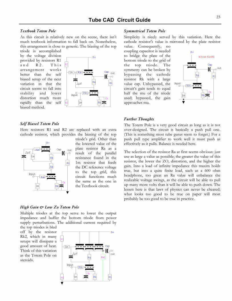
Textbook Totem Pole As this circuit is relatively new on the scene, there isn’t much textbook information to fall back on. Nonetheless, this arrangement is close to generic. The biasing of the top triode is accomplished by the voltage division provided by resistors R1 a n d R 2 . T h i s arrangement works better than the self biased setup of the next variation in that the circuit seems to fall into stability and lower distortion much more rapidly than the self biased method.
Self Biased Totem Pole Here resistors R1 and R2 are replaced with an extra cathode resistor, which provides the biasing of the top
triode’s grid. Other than the lowered value of the plate resistor Ra as a result of the parallel resistance found in the 1m resistor that feeds the DC reference voltage to the top grid, this circuit functions much the same as the one in the Textbook circuit.
High Gain & Low Zo Totem Pole Multiple triodes at the top serve to lower the output impedance and buffer the bottom triode from power supply perturbations. The additional current required by the top triodes is bled off by the resistor Rk2, which in many setups will dissipate a good amount of heat. Think of this variation as the Totem Pole on steroids.
B+
input
outCap.1µf
CkRk
Rl
Rin
1m
Ra
1m Rk
Rin
B+
input
out
Cap
.1µf
Rk Rl
Rin
Rk2Ra
1m
R1
R2
Ck1m
B+
input
outCap
Ck
.1µf
Rk
Rl
Rin
1m
Ra
1m Rin
R1
R2
Symmetrical Totem Pole Simplicity is nicely served by this variation. Here the cathode resistor’s value is mirrored by the plate resistor value. Consequently, no coupling capacitor is needed to bridge the plate of the bottom triode to the grid of the top triode. The symmetry can be broken by bypassing the cathode resistor Rk with a large value cap. Unbypassed, the circuit’s gain tends to equal half the mu of the triode used; bypassed, the gain approaches mu.
Further Thoughts The Totem Pole is a very good circuit as long as it is not over-designed. The circuit is basically a push pull one. (This is something most tube gurus seem to forget.) For a push pull type amplifier to work well it must push as effectively as it pulls. Balance is needed here.
The selection of the resistor Ra at first seems obvious: just use as large a value as possible; the greater the value of this resistor, the lower the ZO, distortion, and the higher the gain. Into a load of infinite impedance this maxim holds true, but into a quite finite load, such as a 600 ohm headphone, too great an Ra value will unbalance the realizable voltage swings, as the circuit will be able to pull up many more volts than it will be able to push down. The lessen here is that laws of physics can never be cheated; what looks too good to be true on paper will most probably be too good to be true in practice.
B+
input
outCap
Where Ra=Rk
CkRk
Rl
Rin
1m
Ra

Tube CAD Circuit Guide 24
W H I T E C A T H O D E F O L L O W E R Earlier, we said the that the Cathode Follower is the workhorse of tube circuits; well then this must be the Clydesdale. This buffer circuit offers a very low output impedance, almost unity gain, and a symmetrical push-pull current swing. How? Feedback from the plate of the top tube to the bottom tube’s grid is the answer. Although “feedback” is a dirty word in many High End audio circles, in this circuit it yields some amazing results. Just stop and ponder how amazing it is to have a tube circuit with an output impedance as low as a few ohms. Truly amazing. Still, in spite of a flurry of interest in the late 80’s, this circuit has not caught on. With the advent of the some very fine headphones, e.g. Grado, it might be time to review the merits of this circuit once more, as one 6DJ8 and a 100 ohm plate resistor can make an excellent headphone buffer amplifier.
The circuit works by using a plate resistor to monitor any variations in the top tube’s cathode to grid voltage. Any current variation in this circuit current path will define a variation in voltage across the plate resistor, which would then be transmitted to the bottom tube’s grid and result in a greater or lesser current draw until the variation in voltage was countervailed.
⇑ Extremely low output impedance. ⇑ Very low distortion. ⇑ Nearly unity gain. ⇑ Good PSRR. ⇑ Push-Pull operation. ⇓ Fairly complex. ⇓ Feedback. ⇓ Internal coupling capacitors. ⇓ High heater to cathode voltage differentials. ⇔ High transconductance tubes work well. ⇔ Should be used in a fairly high current operation.
AKA Push Pull Cathode Follower, Cascoded Cathode Follower
Textbook White Cathode Follower This arrangement makes use of all that is needed to define a White Cathode Follower: a plate resistor whose fluctuating voltage differential from fluctuating current demands through the top triode is AC coupled to the grid of the bottom triode by a c a p a c i t o r . T h e bypassing of the cathode resistor Rk lowers the already low Zo even further.
B+
in
outCap
.1µfVref
Rl
1m
Ra
RkCk
Rin
Split Rail Voltage White Cathode Follower Here the input is at the DC reference voltage, which necessitates the presence of a negative power supply. In this arrangement the negative supply voltage is equal to the positive supply voltage, but negative. The circuit could be DC coupled at the output by including a second bypassed cathode resistor between the top triode’s cathode and the bottom triode’s plate and using the bottom of this resistor as the output.
Symmetrical White Cathode Follower Here is the deconstructionist version of the White Cathode Follower, basically the same performance as the other variations, but twice the heat dissipated. Still there might be some use for this variation in a pre-amp, where the smaller current variations that result from the use of this circuit over the single current path White Cathode Fol-lowers would prove advantageous.
Transformer Loaded White Cathode Follower The transformer offers the advantage of not dissipating the heat or exhibiting the voltage drop of a plate load resistor. Functionally, the transformer achieves the same goal of converting the changes in current through the top tube into voltage signal for the bottom tube. Furthermore, the use of the transformer might make for an easier bipolar power supply arrangement, wherein the B+ voltage is equal in magnitude to the B- voltage.
B+
input
outCap
B-
.1µf
Ck Rl
1m
Ra
Rk
1m
Rin
Rk Ra
Rin
Where,B- = -(B+)
B+
input
outCap
.1µf
Ck
Rl
1m
Ra2
Rk
Ra
Vref Rk2
B+
input
outCap
Ck
Vref Rl
Rk
Ra
Rin
1:1