audi b8 front mount intercooler - eurocode tuning · pdf filelimited one (1) year warranty ....
TRANSCRIPT

Audi B8 Front Mount Intercooler
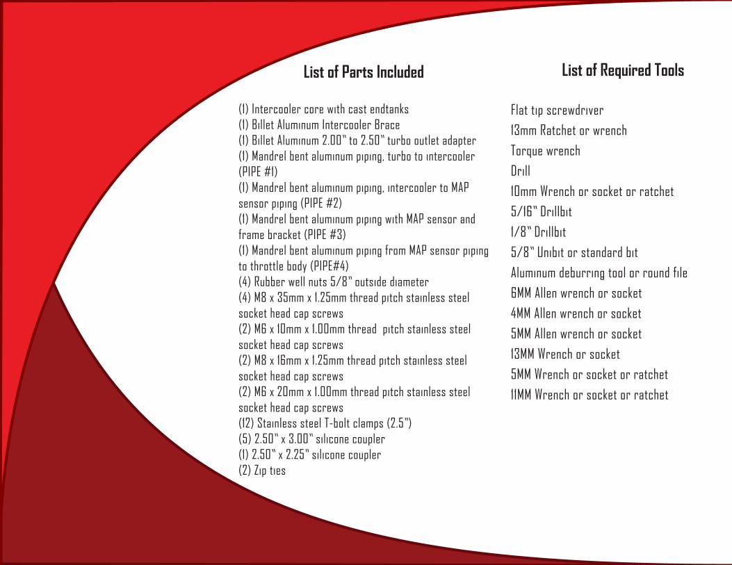
List of Parts Included
(1) Intercooler core with cast endtanks(1) Billet Aluminum Intercooler Brace(1) Billet Aluminum 2.00” to 2.50” turbo outlet adapter(1) Mandrel bent aluminum piping, turbo to intercooler (PIPE #1)(1) Mandrel bent aluminum piping, intercooler to MAP sensor piping (PIPE #2)(1) Mandrel bent aluminum piping with MAP sensor and frame bracket (PIPE #3)(1) Mandrel bent aluminum piping from MAP sensor piping to throttle body (PIPE#4)(4) Rubber well nuts 5/8” outside diameter(4) M8 x 35mm x 1.25mm thread pitch stainless steel socket head cap screws(2) M6 x 10mm x 1.00mm thread pitch stainless steel socket head cap screws(2) M8 x 16mm x 1.25mm thread pitch stainless steel socket head cap screws(2) M6 x 20mm x 1.00mm thread pitch stainless steel socket head cap screws(12) Stainless steel T-bolt clamps (2.5”)(5) 2.50” x 3.00” silicone coupler(1) 2.50” x 2.25” silicone coupler(2) Zip ties
List of Required Tools
Flat tip screwdriver13mm Ratchet or wrenchTorque wrenchDrill10mm Wrench or socket or ratchet5/16” Drillbit1/8” Drillbit5/8” Unibit or standard bitAluminum deburring tool or round file6MM Allen wrench or socket 4MM Allen wrench or socket5MM Allen wrench or socket13MM Wrench or socket5MM Wrench or socket or ratchet11MM Wrench or socket or ratchet

Proper service and repair procedures are vital to the safe, reliable operation of all motor vehicles as well as the personal safety of those performing the
repairs. Standard safety procedures and precautions (including use of safety goggles and proper tools and equipment) should be followed at all times to eliminate the possibility of personal injury or improper service which could
damage the vehicle or compromise its safety.

1
Remove sound baffle (8) PHILLIPS screws
Right side (US Passenger)
STEP 1
Figure 1

2
Remove (4) T25 screws from bumper
STEP 2
Figure 2

3
Remove passenger fender liner (2) T25 screws and plastic clips (6)
STEP 3
Figure 3

4
STEP 4 Remove 10mm bolt (socket with 24” extension) from
inside fender that attaches bumper to fender
Figure 4
5
Left side (US Drivers)
Repeat steps 1-4 on the Driver’s side of the car.
STEP 5

6
STEP 1 Center of car
Remove cowl cover (4) T27 screws
Figure 5

7
STEP 2 Remove engine cover
Figure 6
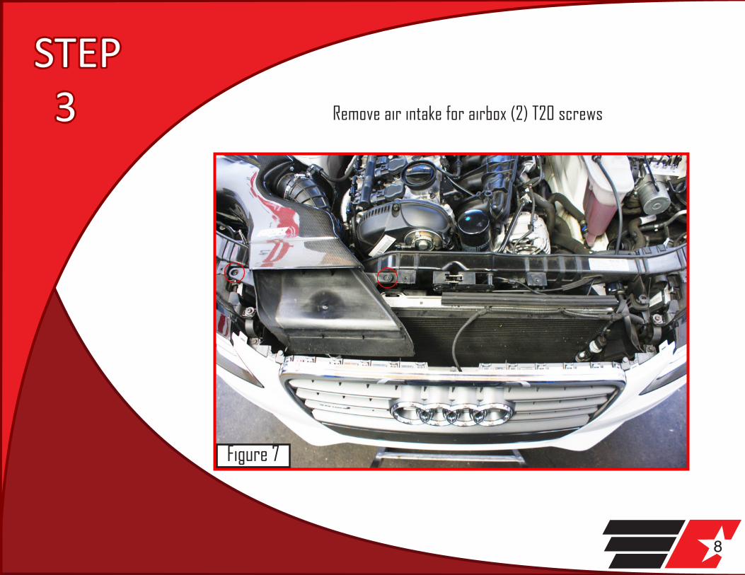
8
STEP 3 Remove air intake for airbox (2) T20 screws
Figure 7
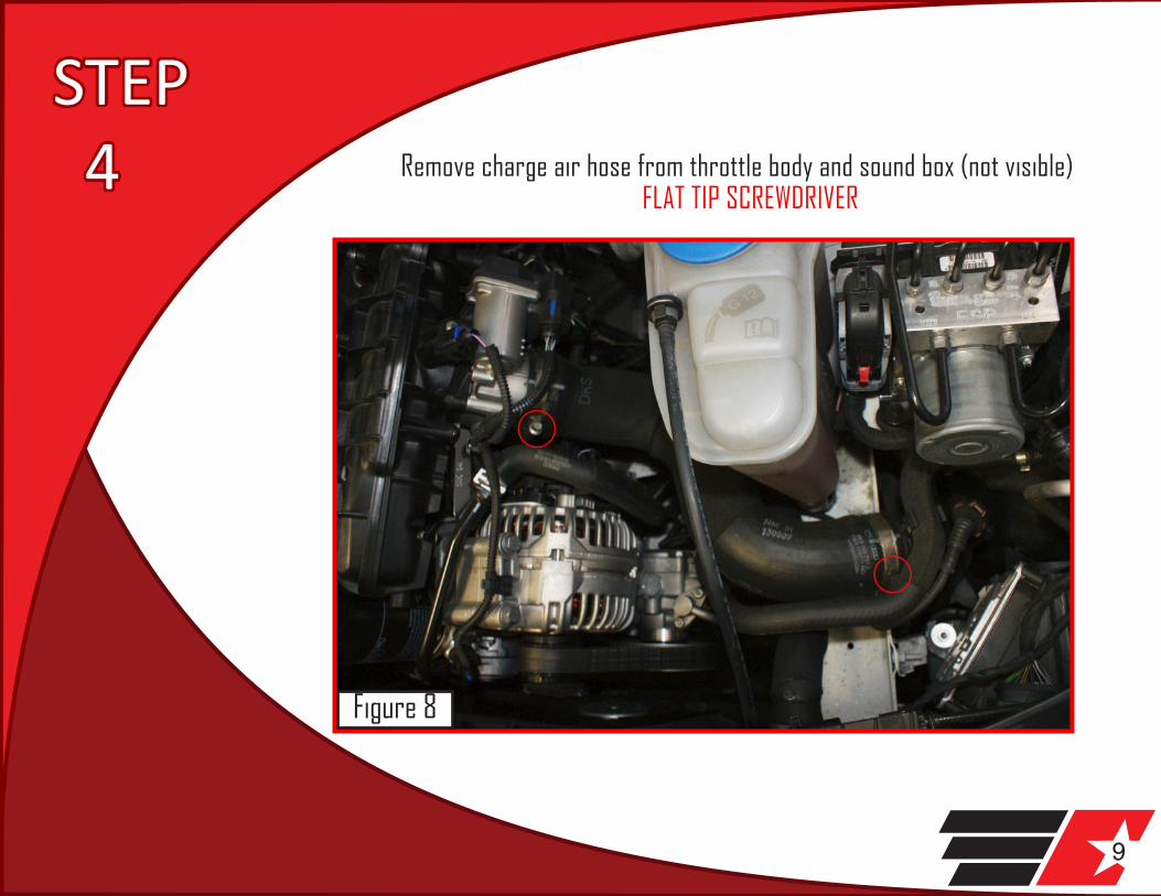
9
STEP 4 Remove charge air hose from throttle body and sound box (not visible)
FLAT TIP SCREWDRIVER
Figure 8
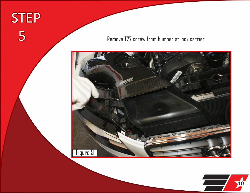
10
STEP 5 Remove T27 screw from bumper at lock carrier
Figure 9

11
STEP 6 Remove coming home sensor (if equipped) and possibly the outside air
temperature sensor
Figure 10

12
STEPS 7&8 Gently pull away bumper from fender on passenger side.
Take care not to damage clips
Gently pull away bumper from drivers side. Take care not to damage clips
Figure 11
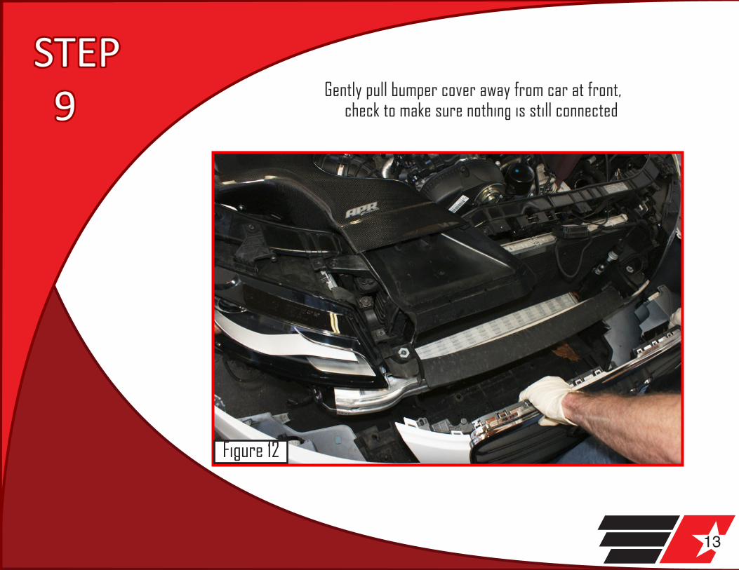
13
STEP 9 Gently pull bumper cover away from car at front,
check to make sure nothing is still connected
Figure 12

14
STEP 10 Place bumper in a safe and secure location being careful not to scratch it
Figure 13
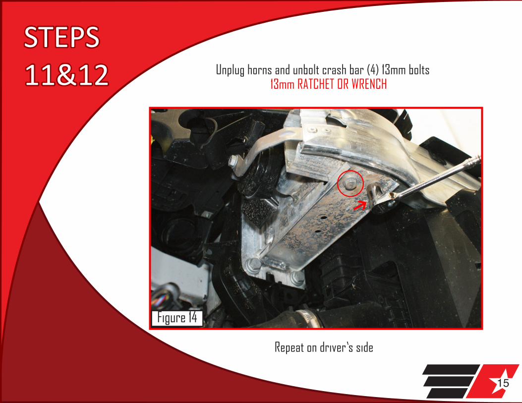
15
STEPS11&12 Unplug horns and unbolt crash bar (4) 13mm bolts
13mm RATCHET OR WRENCH
Repeat on driver’s side
Figure 14

16
STEP 13 Remove crash bar by pulling away from car
Figure 15
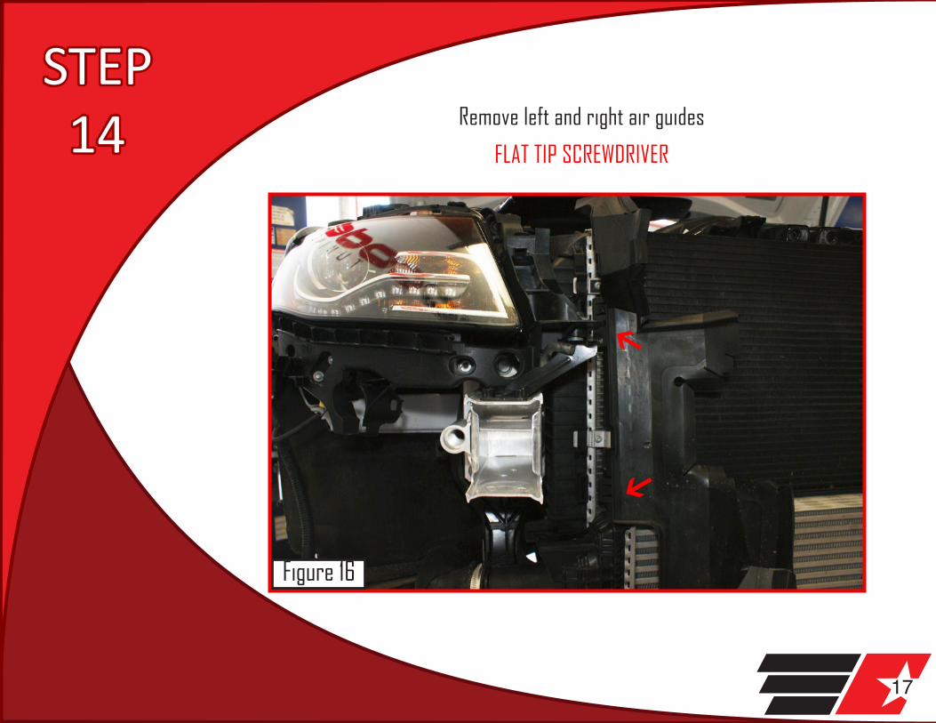
17
STEP 14 Remove left and right air guides
FLAT TIP SCREWDRIVER
Figure 16

18
STEP 15 Remove charge air piping from core and turbo on passenger
side FLAT TIP SCREWDRIVER
Figure 17
19
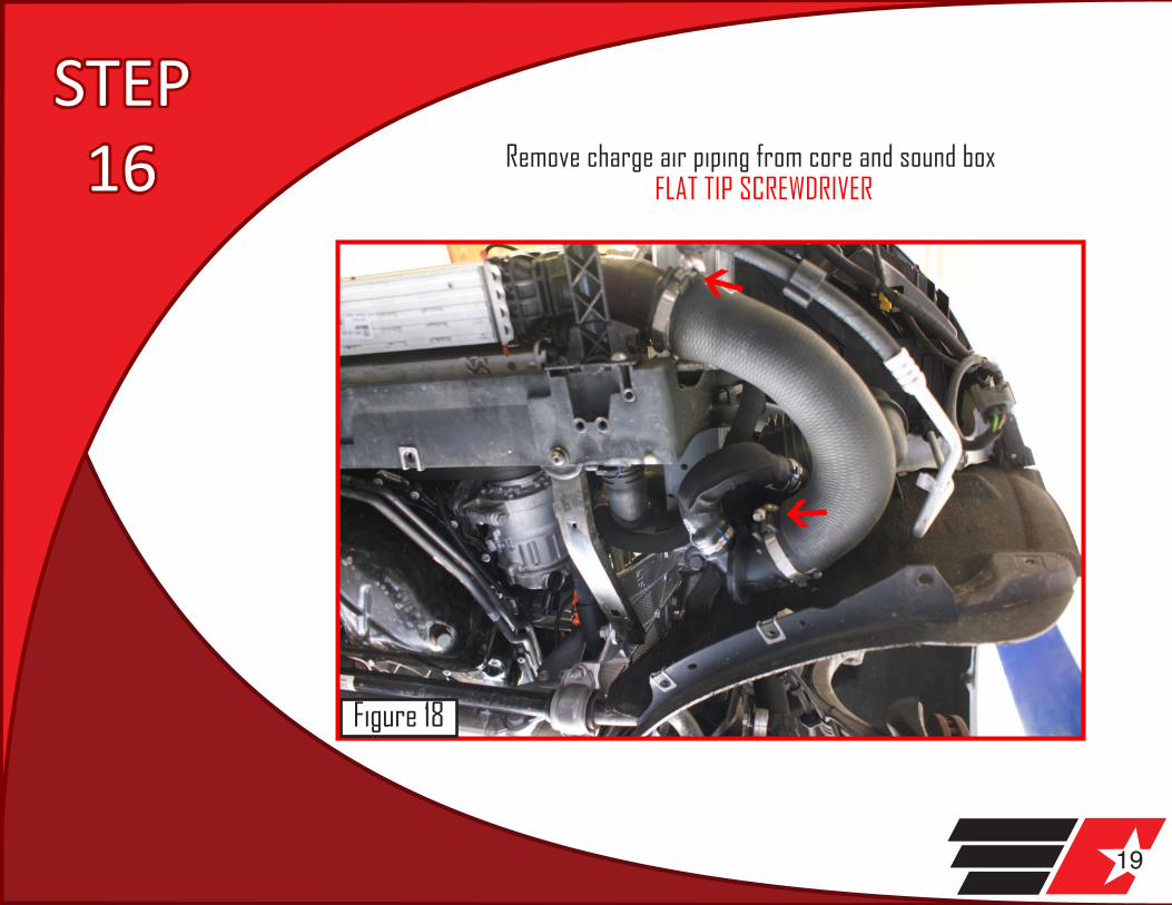
STEP 16 Remove charge air piping from core and sound box
FLAT TIP SCREWDRIVER
Figure 18

20
STEP 17 Unplug MAP(Mass Air Pressure) sensor
Figure 19

21
STEP 18 Remove sound box (3) 10mm nuts
10mm WRENCH OR SOCKET AND RATCHET
Figure 20

22
STEP 19 Remove I/C core (1) T25 screw on drivers side
Figure 21

23
STEP 20 On the passenger side, depress clip and rotate core away
from front of car towards ground, lift up and remove
Figure 22

24
STEP 21 Remove 2.0” turbo outlet adapter (3) 5mm capscrews from
compressor housing
Figure 23
25
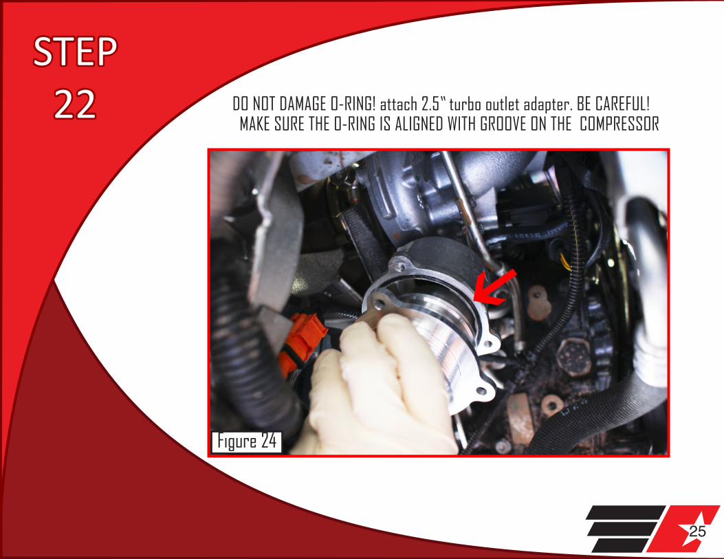
STEP 22 DO NOT DAMAGE O-RING! attach 2.5” turbo outlet adapter. BE CAREFUL!
MAKE SURE THE O-RING IS ALIGNED WITH GROOVE ON THE COMPRESSOR
Figure 24

26
STEP 23 Remove lock carrier support (1) T27 screw
Figure 25
27
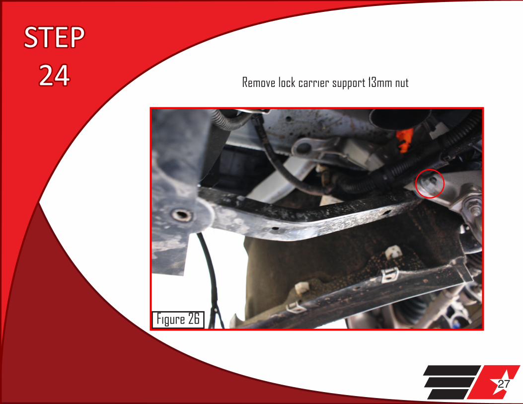
STEP 24 Remove lock carrier support 13mm nut
Figure 26

28
STEP 25 Place short silicone coupler on turbo outlet and attach with T-bolt
clamp, tighten (do not over tighten) with 11mm socket and ratchet or 11mm wrench. If you are having a difficult time with the T-bolt clamp,
temporarily remove one of the turbo outlet bolts.
Figure 27

29
STEPS 1&2 PUTTING TOGETHER REBAR
Secure rebar in a vice or a suitable workspace for drilling.
Remove the air guide from the rebar with a FLAT TIP SCREWDRIVER.
Figure 28

30
STEP 3 Attach billet intercooler core support to two holes in rebar with
the (2) supplied 4mm capscrews (just hand tighten for now). 4MM ALLEN WRENCH OR SOCKET
Figure 29

31
STEP 4
Mark the rebar for drilling by using a 5/16” drill bit in all four countersunk holes that are in the billet support
brace (can be done by hand or by lightly drilling) 5/16” DRILLBIT and DRILL
Figure 30

32
STEP 5
Remove billet support brace from crash bar. 4MM ALLEN WRENCH OR SOCKET
Figure 31

33
STEP 6
Drill (4) pilot holes in crashbar with a 1/8” drillbit 1/8” DRILLBIT and DRILL
Figure 32

34
STEP 7 Using a unibit (Stepped Drill bit), enlarge the (4) pilot holes
to exactly 5/8” UNIBIT or STANDARD BIT and DRILL. Blow or brush off all excess aluminum from drilling
Figure 33
35
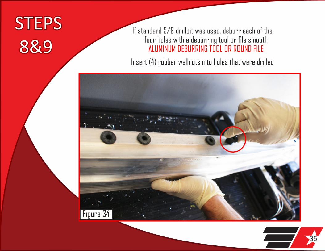
STEPS 8&9
If standard 5/8 drillbit was used, deburr each of the four holes with a deburring tool or file smooth
ALUMINUM DEBURRING TOOL OR ROUND FILE
Insert (4) rubber wellnuts into holes that were drilled
Figure 34
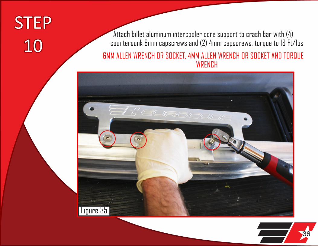
36
STEP 10
Attach billet aluminum intercooler core support to crash bar with (4) countersunk 6mm capscrews and (2) 4mm capscrews, torque to 18 Ft/lbs
6MM ALLEN WRENCH OR SOCKET, 4MM ALLEN WRENCH OR SOCKET AND TORQUE WRENCH
Figure 35

37
STEP 11
Attach intercooler core to billet intercooler core support with (2) 5mm capscrews (loctite recommended, torque to 18 Ft/lbs) make
sure that the baffled inlet side is to the left (passenger side) of car. 5MM ALLEN WRENCH OR SOCKET AND TORQUE WRENCH
Figure 36
38
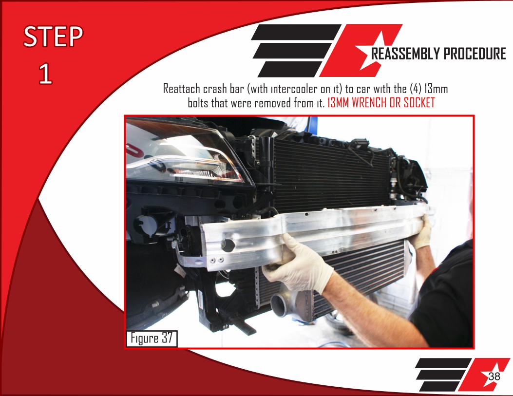
STEP 1
REASSEMBLY PROCEDURE
Reattach crash bar (with intercooler on it) to car with the (4) 13mm bolts that were removed from it. 13MM WRENCH OR SOCKET
Figure 37
39
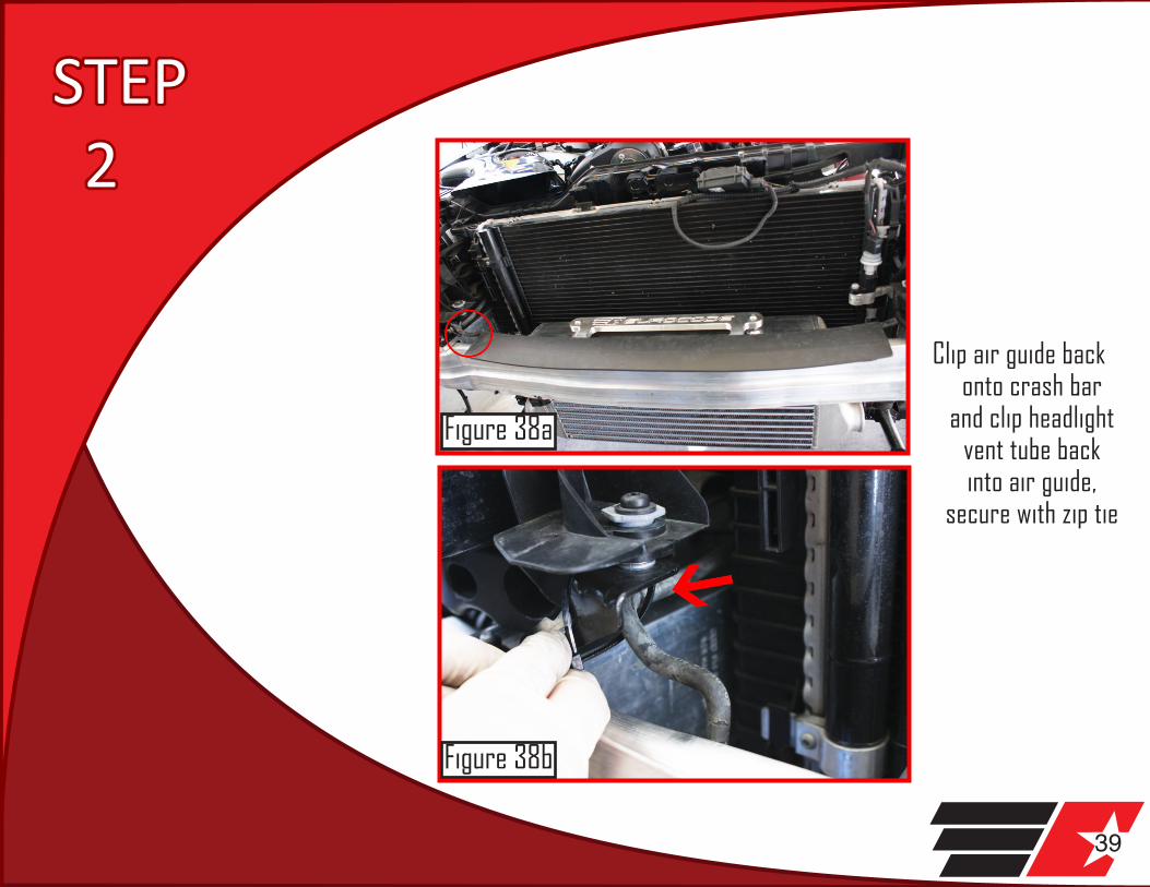
STEP 2
Clip air guide back onto crash bar
and clip headlight vent tube back into air guide,
secure with zip tie
Figure 38a
Figure 38b
40
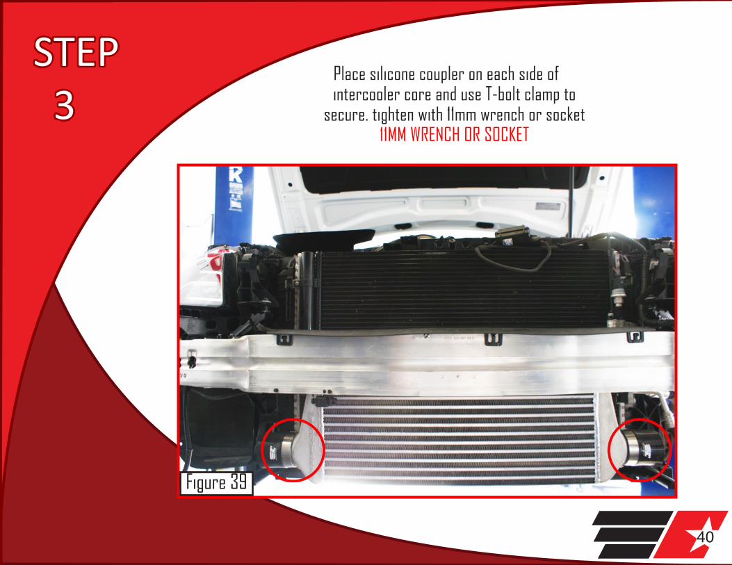
STEP 3
Place silicone coupler on each side of intercooler core and use T-bolt clamp to
secure. tighten with 11mm wrench or socket 11MM WRENCH OR SOCKET
Figure 39
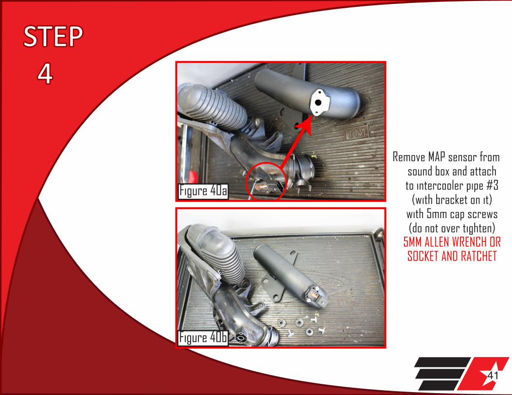
41
STEP 4
Remove MAP sensor from sound box and attach to intercooler pipe #3
(with bracket on it) with 5mm cap screws (do not over tighten)
5MM ALLEN WRENCH OR SOCKET AND RATCHET
Figure 40a
Figure 40b
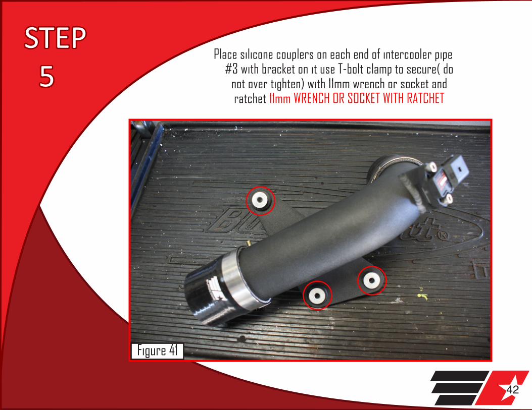
42
STEP 5
Place silicone couplers on each end of intercooler pipe #3 with bracket on it use T-bolt clamp to secure( do
not over tighten) with 11mm wrench or socket and ratchet 11mm WRENCH OR SOCKET WITH RATCHET
Figure 41

43
STEP 6
Transfer (3) rubber bushings from factory sound box to intercooler pipe with bracket (there are three different sizes,
make sure each goes in their respective place) to remove bushing, first push out the metal inset, then push out bushing
Figure 42

44
STEP 7
Attach intercooler pipe with bracket to car with the (3) 13mm nuts that were removed from car 13MM WRENCH OR SOCKET WITH RATCHET
Figure 43
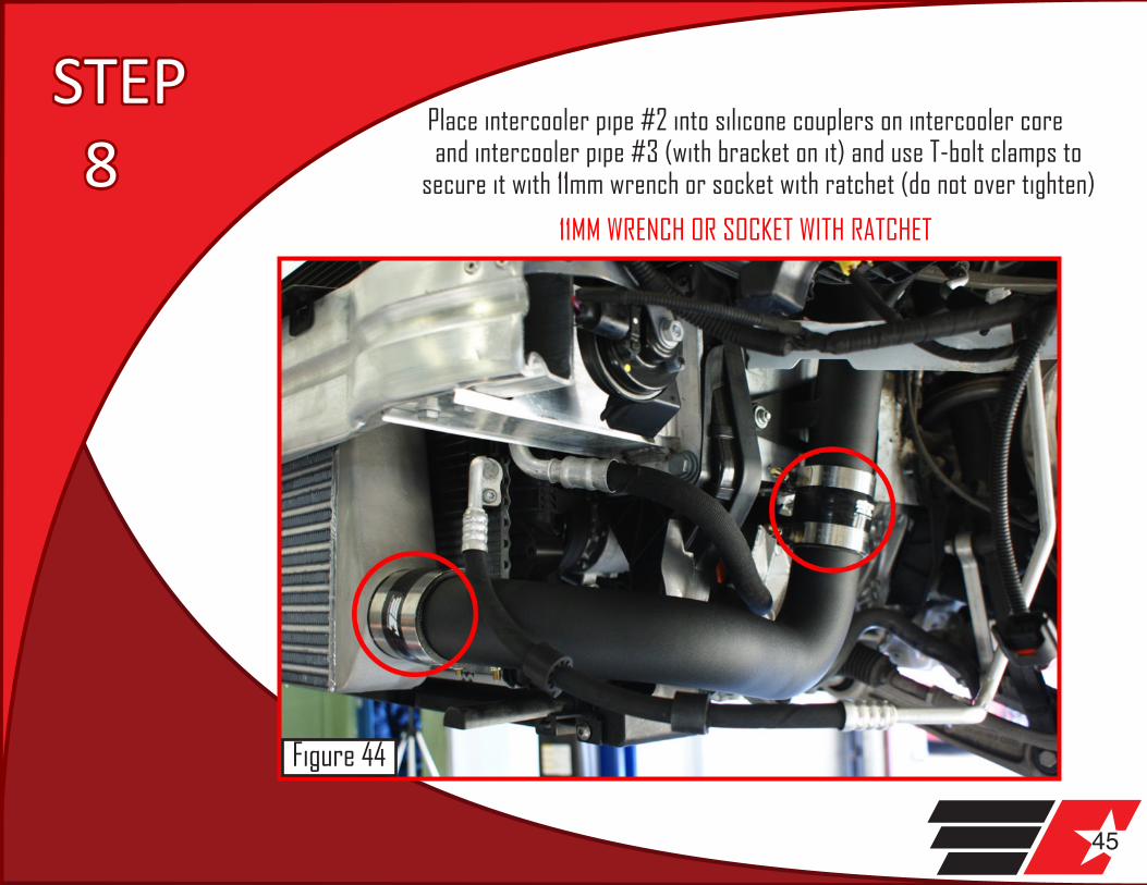
45
Place intercooler pipe #2 into silicone couplers on intercooler core and intercooler pipe #3 (with bracket on it) and use T-bolt clamps to
secure it with 11mm wrench or socket with ratchet (do not over tighten)
11MM WRENCH OR SOCKET WITH RATCHET
STEP 8
Figure 44

46
Place Intercooler pipe #4 into silicone couplers between throttle body and intercooler pipe #3 (with bracket on it) using (1) T-bolt clamp and the original worm clamp on the throttle body. Secure it with 11mm wrench or socket with
ratchet (do not over tighten) and a flat tip screwdriver on the throttle body side 11MM WRENCH OR SOCKET WITH RATCHET, FLAT TIP SCREWDRIVER
Plug MAP sensor harness into the MAP sensor.
STEPS9&10
Figure 45
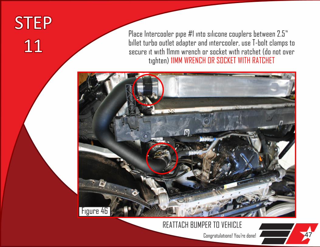
47
Place Intercooler pipe #1 into silicone couplers between 2.5” billet turbo outlet adapter and intercooler, use T-bolt clamps to secure it with 11mm wrench or socket with ratchet (do not over
tighten) 11MM WRENCH OR SOCKET WITH RATCHET
REATTACH BUMPER TO VEHICLE
STEP 11
Figure 46
Congratulations! You’re done!
LIMITED ONE (1) YEAR WARRANTY
Eurocode Tuning, Inc. (EUROCODE) warrants to the original purchaser that our B8 A4/A5 Intercooler Upgrade Kit (PRODUCT) will be free of defects in material and workmanship for a period of one (1) year from the date of purchase. This Warranty applies only to the original purchaser of the PRODUCT. To obtain any warranty service, you must provide EUROCODE with proof of purchase and date of purchase acceptable to EUROCODE, such as a copy of your purchase receipt. This warranty does not cover the removal or reinstallation of the product. EUROCODE will, at its option, repair, replace or refund the purchase price of a defective component, provided you return the defective component during the warranty period, transportation charges prepaid, to Eurocode Tuning’s Service Department or a Factory Authorized Service Center.
Attach your name, address, telephone number, a description of the problem, and a copy of your sales receipt. All returns must be accompanied by a Return Goods Authorization (RGA) number and such number shall be written clearly on the outside of the box. RGA numbers may be obtained by calling EUROCODE at 1-310-294-8108 This warranty does not apply to the (i) metal finish or (ii) if the product/component has been damaged by accident, abuse, misuse, collision, modification, misapplication, improper installation, or improper service. This warranty is void if any EUROCODE serial number has been removed or defaced. Commercial or industrial use or application, or any motorsports use voids the warranty.
THE WARRANTY SET FORTH ABOVE IS THE ONLY WARRANTY. THERE ARE NO OTHER WARRANTIES, EXPRESS OR IMPLIED, INCLUDING BUT NOT LIMITED TO IMPLIED WARRANTIES OF MERCHANTABILITY OR FITNESS FOR A PARTICULAR PURPOSE. ANY IMPLIED WARRANTY WHICH BY LAW MAY NOT BE EXCLUDED IS LIMITED IN DURATION TO ONE (1) YEAR FROM THE DATE OF ORIGINAL RETAIL PURCHASE OF THE PRODUCT.
No EUROCODE dealer, agent or employee is authorized to make any modification, extension or addition to this warranty.
EUROCODE SHALL NOT BE LIABLE FOR SPECIAL, INDIRECT, INCIDENTAL OR CONSEQUENTIAL DAMAGES (INCLUDING, BUT NOT LIMITED TO, LOST PROFITS, DOWN TIME OR LOSS OF USE) UNDER ANY LEGAL THEORY, EVEN IF EUROCODE WAS ADVISED OF THE POSSIBILITY OF SUCH DAMAGES.
Some states do not allow the exclusion of implied warranties or the exclusion or limitation of liability for incidental or consequential damages, or limitations on how long an implied warranty lasts, so the above limitation or exclusion may not apply to you. This warranty gives you specific legal rights. You may also have other rights that vary from state to state. EUROCODE reserves the right to change Product/component design without notice. In situations in which EUROCODE has changed a Product/component design, EUROCODE shall have no obligation to upgrade or otherwise modify previously manufactured Products/components.
Warranty inquires and Products returned for warranty service should be sent to:
Eurocode Tuning, Inc.Customer Service Department1908 Del Amo BlvdTorrance, CA 905011-310-294-81081-310-212-7141 International Fax