au 2014 class handout ab6557 practically dynamo...
TRANSCRIPT
Practically Dynamo: Practical Uses for Dynamo within Revit
Marcello Sgambelluri – BIM Director - John A. Martin & Associates
AB6557 & AB7977
Have you ever wanted to learn the Dynamo visual programming language extension for Revit software but you decided to run and hide instead because you thought it was only for super-complex geometry and twisting towers? It’s not. The Dynamo extension is for every Revit user. This lecture will describe the uses of the Dynamo extension and explain how it interacts with Revit software to help any Revit user. The Dynamo extension is a program that uses visual programming, but don't let that scare you. This lecture will teach attendees how to use the Dynamo extension even if they have no prior programming experience. Now that the Dynamo extension and Design Script programming language have merged, the Dynamo extension is even easier to learn and use. This lecture will also give attendees very gradual doses of the Dynamo extension and visual programming so they leave with the skills to apply the Dynamo extension to practical Revit software workflows. And don't forget that the Dynamo extension is an add-on to Revit software.
LearningObjectives
At the end of this class, you will be able to:
Learn the answer to the question: What is the Dynamo extension?
Learn how to program using visual programming
Learn how to create practical uses in the office using the Dynamo extension for Revit software
Learn to script in the Dynamo extension using DesignScript programming language

Practically Dynamo: Practical Uses for Dynamo Within Revit
2
AbouttheSpeaker
Marcello Sgambelluri is the Building Information Modeling (BIM) director at John A. Martin & Associates, Inc., in Los Angeles, California. Marcello is heavily devoted to helping advance the use and knowledge of BIM Solutions within the architecture, engineering, and construction community. He is well known for modeling elements and creating workflows that others did think not possible. He also frequently presents at Autodesk University, where attendees voted him the top-rated speaker for 2 years in a row. He has worked on many well-known projects in the past, including the Walt Disney Concert Hall in Los Angeles, California; the Ray and Maria Stata Center at the Massachusetts Institute of Technology; and the Tom Bradley International Terminal Expansion at Los Angeles International Airport. Marcello received BS and MS degrees in civil engineering, and he is a licensed civil and structural engineer.
Twitter: @marcellosgamb
Blogs: www.therevitcomplex.blogspot.com
www.simplydynamo.blogspot.com
Email: [email protected]
Practically Dynamo: Practical Uses for Dynamo Within Revit
3
Contents
INTRODUCTION.....................................................................................................................................5
What is Dynamo? ............................................................................................................................................... 5
What version is this? That’s so yesterday’s Build. ............................................................................................... 8
Every Revit User gets to touch the API ................................................................................................................ 9
Downloading and Installing Dynamo is Easy! ..................................................................................................... 10
Dynamo Basics and the interface. ...................................................................................................................... 12
GETTINGANDSETTINGPARAMETERS........................................................................................14
Using Single Selection (Select Model Element Node) ......................................................................................... 15
Using Multi Selection (Select Model Elements Node) ......................................................................................... 22
SELECTIONOFELEMENTSUSINGDYNAMO................................................................................24
Using Selection By Category .............................................................................................................................. 24
Using Selection By Family Type Selection........................................................................................................... 25
Using Selection By Element Type ....................................................................................................................... 26
Using Selection By Category Revisited ............................................................................................................... 27
Confusing Selection node names ....................................................................................................................... 28
PROFILEORDER...................................................................................................................................29
Sample and Description .................................................................................................................................... 29
Spline Order ...................................................................................................................................................... 30
CANOPYFRAMING...............................................................................................................................35
Intersection method (edge beam) ..................................................................................................................... 35
Intersection Method Single Beam at Grid .......................................................................................................... 38
Practically Dynamo: Practical Uses for Dynamo Within Revit
4
Intersection Method (Multiple Beams at Grids) ................................................................................................. 43
EXTRACTINGADAPTIVECOMPONENTPOINTS........................................................................46
ROOMTOFLOOR.................................................................................................................................50
Workflow .......................................................................................................................................................... 51
Get the Room Boundaries for the “outline” input port ...................................................................................... 52
Select all the Rooms ................................................................................................................................................ 52
Extract Solid Room Geometry ................................................................................................................................. 53
Get Room Boundary Curves .................................................................................................................................... 55
Get the Floor Type for the floorType input port ................................................................................................. 58
Further modeling and considerations ................................................................................................................ 61
Thickness Adjustment ............................................................................................................................................. 61
Multi Level Adjustment: Creating Floors for all levels at once ................................................................................ 62
Multi Level Adjustment: Creating Floors for each level separately ........................................................................ 62
EXCELINPUTTOPORETAININGWALL........................................................................................63
Get the data from Excel ..................................................................................................................................... 64
Change data to make points and create topo in Revit ........................................................................................ 64
Making changes to the topo .............................................................................................................................. 65
DESIGNSCRIPTINGANDTHEREVITCOW..................................................................................66
Practically Dynamo: Practical Uses for Dynamo Within Revit
5
Introduction
WhatisDynamo?This is a very difficult question to answer simply because Dynamo does SO much. Below is my answer to this question and I hope it clarifies it for some of you.
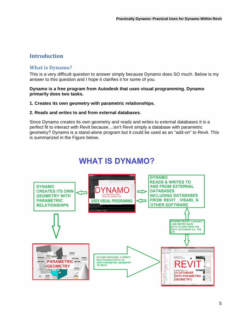
Dynamo is a free program from Autodesk that uses visual programming. Dynamo primarily does two tasks.
1. Creates its own geometry with parametric relationships.
2. Reads and writes to and from external databases.
Since Dynamo creates its own geometry and reads and writes to external databases it is a perfect fit to interact with Revit because....isn’t Revit simply a database with parametric geometry? Dynamo is a stand-alone program but it could be used as an "add-on" to Revit. This is summarized in the Figure below.
Practically Dynamo: Practical Uses for Dynamo Within Revit
6
Dynamo reads and writes back data to and from the Revit database via the Revit API. The data could be just about anything, parameter values, family geometry, and family placement.
Basically Dynamo manipulates the Revit database in ways that the UI (user interface) could not. For example in Dynamo you could set the base of all the walls and all the columns to the same elevation. This means that you could set parameters from different families equal to each other. Would that be helpful?
Dynamo also provides a direct relationship between its OWN geometry and Revit. For example in Dynamo you could model a cone and a plane, find the intersection of those elements (results in a curve) and then assign a Structural Revit Beam IN REVIT to that Dynamo curve and they would be forever "linked" meaning if the dynamo curve changed location then the Revit Beam would change location as well. All the while the original cone, plane, and curve would REMAIN in the dynamo program while the Structural Beam would remain in Revit. The applications for Dynamo and Revit are endless.
Just about any Revit user could learn Dynamo (since it uses visual programming it is very simple to learn) they could access the Revit api and perform simple tasks that only could have previously been performed with writing an add-on or writing a macro with .net language for Revit. Oh and don't forget that Dynamo is completely free and is updated constantly. If you need the latest build or more information visit www.dynamoBIM.org and get started.
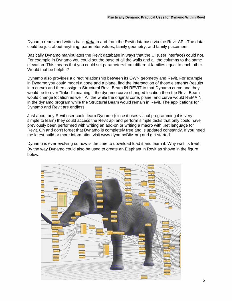
Dynamo is ever evolving so now is the time to download load it and learn it. Why wait its free! By the way Dynamo could also be used to create an Elephant in Revit as shown in the figure below.
Practically Dynamo: Practical Uses for Dynamo Within Revit
7

Practically Dynamo: Practical Uses for Dynamo Within Revit
8
Whatversionisthis?That’ssoyesterday’sBuild.Dynamo is developing so fast that is has daily builds. That means that a new version is released on a daily basis. Of course most of it is untested so there are “stable” builds that are released about every 2 months or so. The latest version of Dynamo (version .74) had the backend code rewritten to include and incorporate Design Script methodology.
Design Script is the easiest text programing language to learn for the non-programmer. I know because I learned it! Basically Dynamo merged Design Script Studio (which was also a visual programming environment) Design Script basically allows Dynamo functionality to be done using simple text driven programming. If you want more information on Design Script visit the following link http://designscript.ning.com/.

Practically Dynamo: Practical Uses for Dynamo Within Revit
9
EveryRevitUsergetstotouchtheAPI Let’s face it the Revit API is a very difficult thing to utilize. For the most part you need to be an Autodesk developer or an experienced .net programmer to use the API and write programs. The API was developed for developers by developers and therefore it could be a very confusing thing to understand let alone try to use for many Revit users.
I am happy to say that Dynamo basically allows users to use the Revit API thru visual programming using “nodes” and “wires” instead of text. This means that any Revit user could use the API and create custom simple routines without having to know .net language or without having to hire an outside API consultant.
Practically Dynamo: Practical Uses for Dynamo Within Revit
10
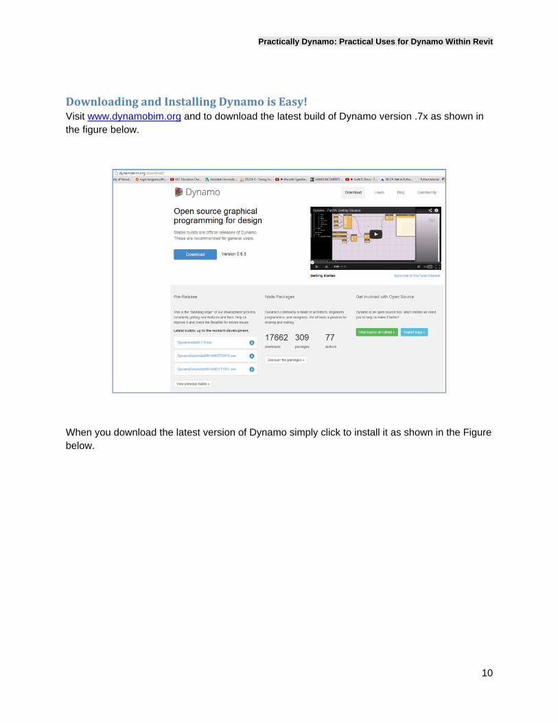
DownloadingandInstallingDynamoisEasy!Visit www.dynamobim.org and to download the latest build of Dynamo version .7x as shown in the figure below.
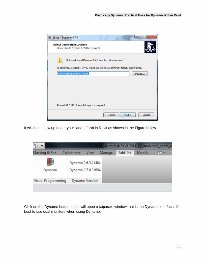
When you download the latest version of Dynamo simply click to install it as shown in the Figure below.
Practically Dynamo: Practical Uses for Dynamo Within Revit
11
It will then show up under your “add-in” tab in Revit as shown in the Figure below.
Click on the Dynamo button and it will open a separate window that is the Dynamo interface. It’s best to use dual monitors when using Dynamo.
Practically Dynamo: Practical Uses for Dynamo Within Revit
12
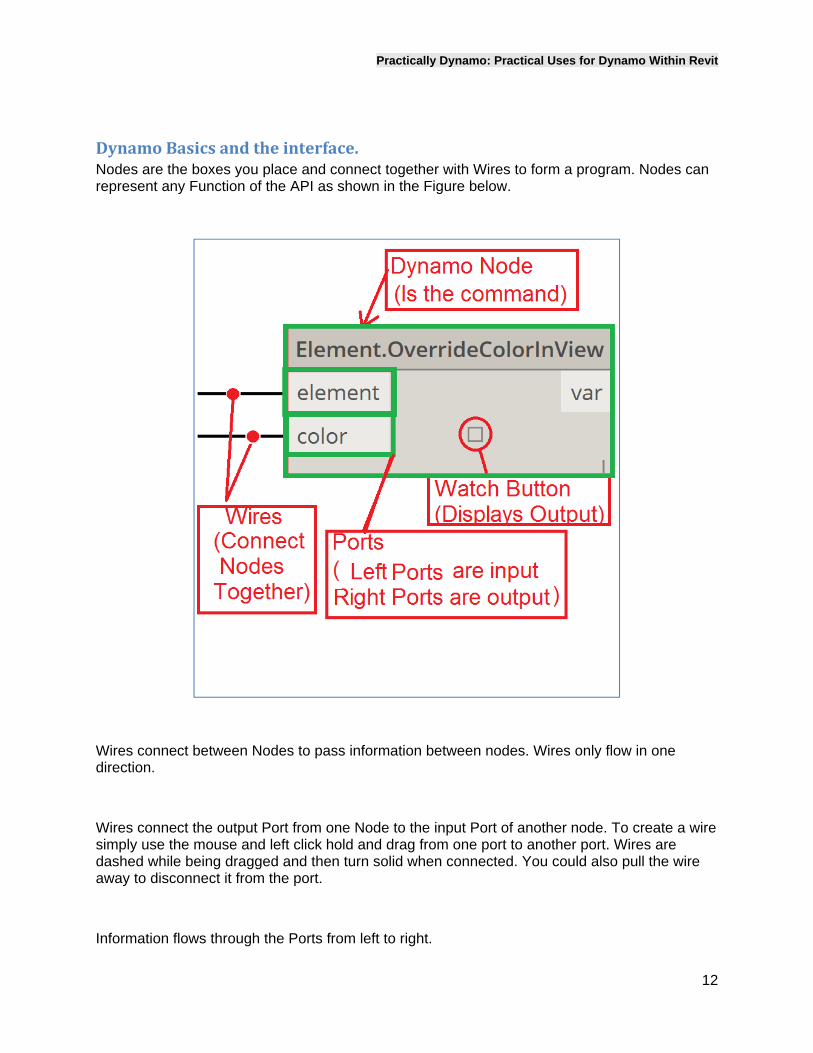
DynamoBasicsandtheinterface.Nodes are the boxes you place and connect together with Wires to form a program. Nodes can represent any Function of the API as shown in the Figure below.
Wires connect between Nodes to pass information between nodes. Wires only flow in one direction.
Wires connect the output Port from one Node to the input Port of another node. To create a wire simply use the mouse and left click hold and drag from one port to another port. Wires are dashed while being dragged and then turn solid when connected. You could also pull the wire away to disconnect it from the port.
Information flows through the Ports from left to right.
Practically Dynamo: Practical Uses for Dynamo Within Revit
13
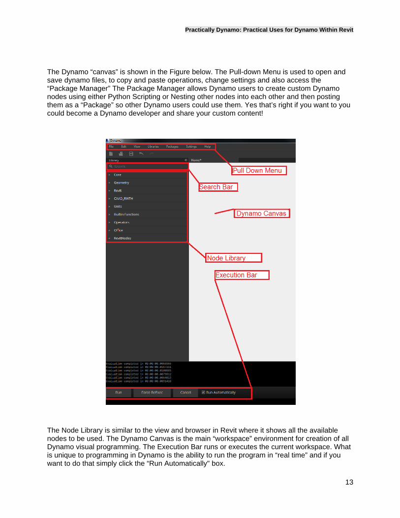
The Dynamo “canvas” is shown in the Figure below. The Pull-down Menu is used to open and save dynamo files, to copy and paste operations, change settings and also access the “Package Manager” The Package Manager allows Dynamo users to create custom Dynamo nodes using either Python Scripting or Nesting other nodes into each other and then posting them as a “Package” so other Dynamo users could use them. Yes that’s right if you want to you could become a Dynamo developer and share your custom content!
The Node Library is similar to the view and browser in Revit where it shows all the available nodes to be used. The Dynamo Canvas is the main “workspace” environment for creation of all Dynamo visual programming. The Execution Bar runs or executes the current workspace. What is unique to programming in Dynamo is the ability to run the program in “real time” and if you want to do that simply click the “Run Automatically" box.
Practically Dynamo: Practical Uses for Dynamo Within Revit
14
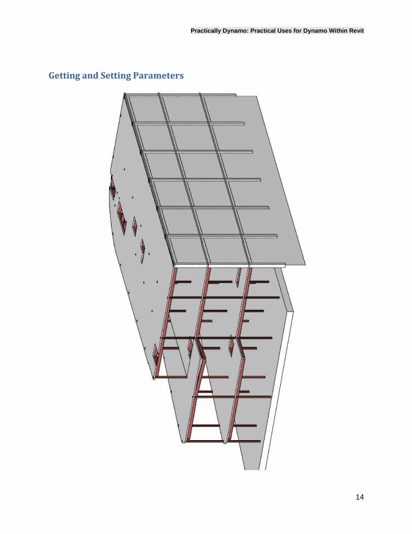
GettingandSettingParameters
Practically Dynamo: Practical Uses for Dynamo Within Revit
15
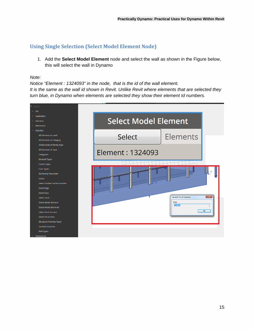
UsingSingleSelection(SelectModelElementNode)
1. Add the Select Model Element node and select the wall as shown in the Figure below, this will select the wall in Dynamo
Note: Notice “Element : 1324093” in the node, that is the id of the wall element. It is the same as the wall id shown in Revit. Unlike Revit where elements that are selected they turn blue, in Dynamo when elements are selected they show their element Id numbers.
Practically Dynamo: Practical Uses for Dynamo Within Revit
16
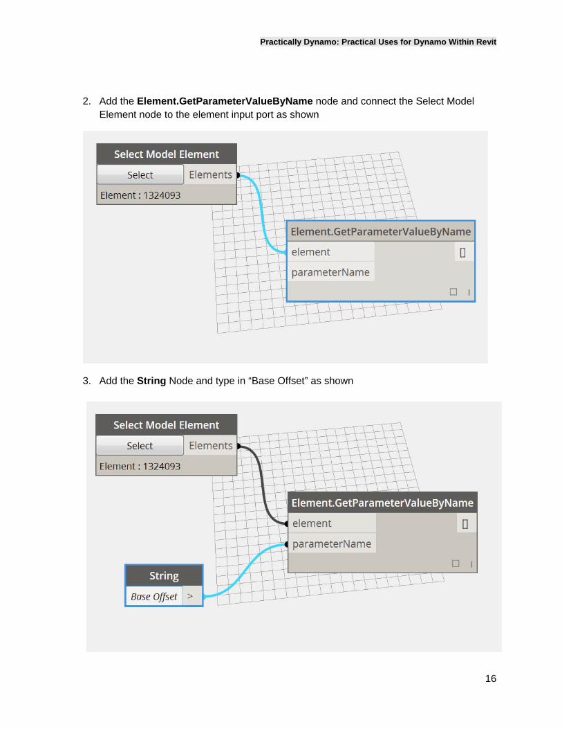
2. Add the Element.GetParameterValueByName node and connect the Select Model Element node to the element input port as shown
3. Add the String Node and type in “Base Offset” as shown
Practically Dynamo: Practical Uses for Dynamo Within Revit
17
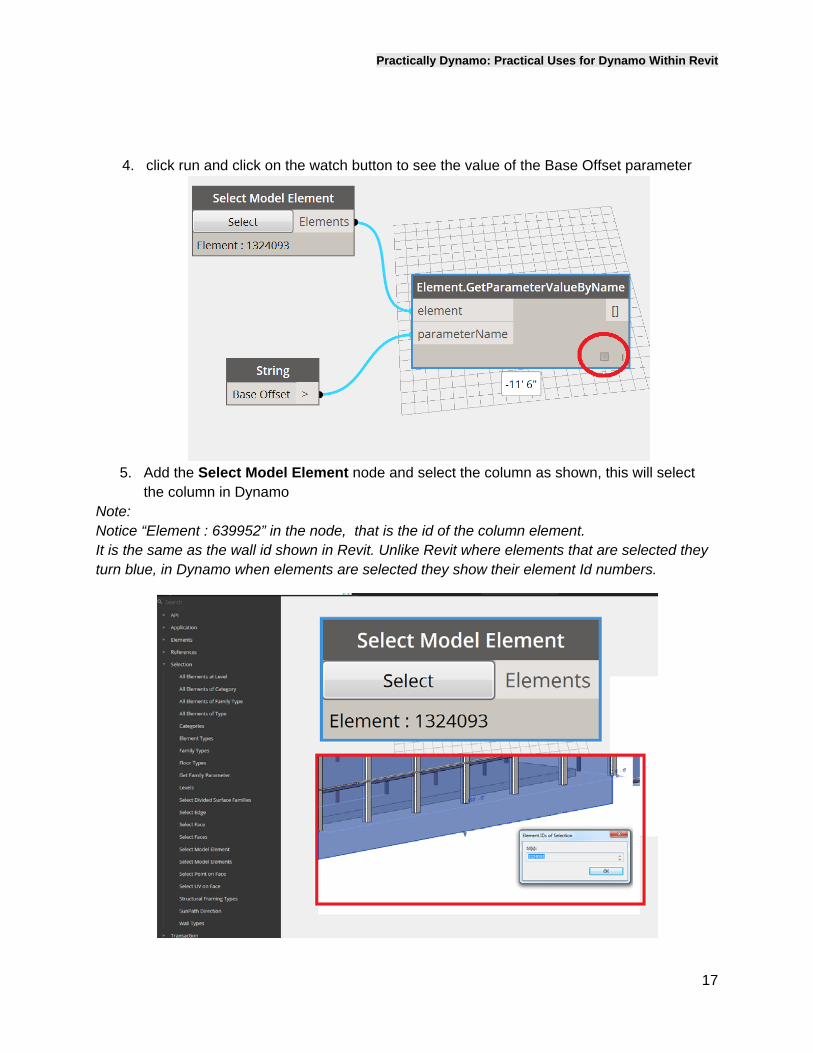
4. click run and click on the watch button to see the value of the Base Offset parameter
5. Add the Select Model Element node and select the column as shown, this will select
the column in Dynamo Note: Notice “Element : 639952” in the node, that is the id of the column element. It is the same as the wall id shown in Revit. Unlike Revit where elements that are selected they turn blue, in Dynamo when elements are selected they show their element Id numbers.
Practically Dynamo: Practical Uses for Dynamo Within Revit
18
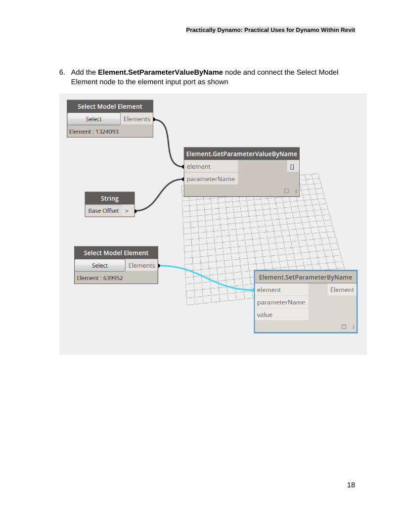
6. Add the Element.SetParameterValueByName node and connect the Select Model Element node to the element input port as shown
Practically Dynamo: Practical Uses for Dynamo Within Revit
19
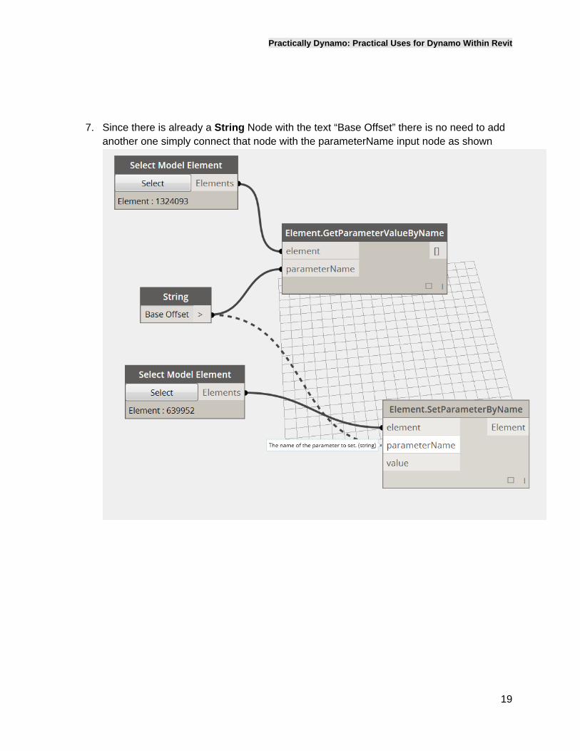
7. Since there is already a String Node with the text “Base Offset” there is no need to add another one simply connect that node with the parameterName input node as shown
Practically Dynamo: Practical Uses for Dynamo Within Revit
20
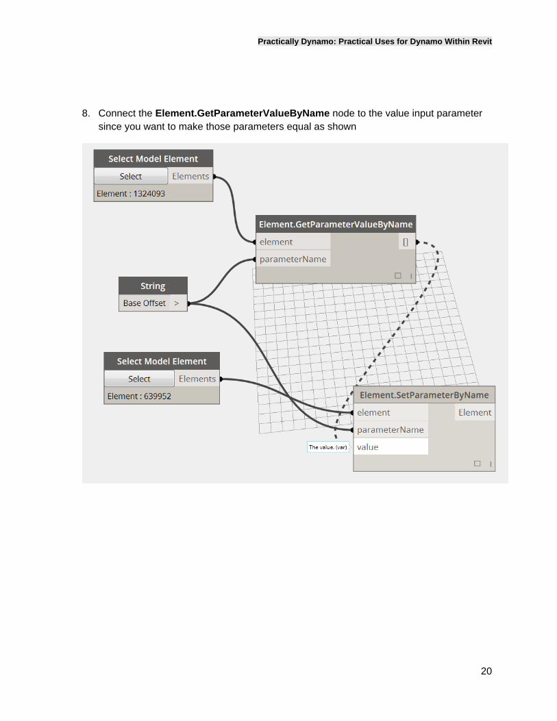
8. Connect the Element.GetParameterValueByName node to the value input parameter
since you want to make those parameters equal as shown
Practically Dynamo: Practical Uses for Dynamo Within Revit
21
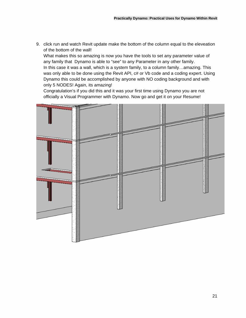
9. click run and watch Revit update make the bottom of the column equal to the eleveation of the bottom of the wall! What makes this so amazing is now you have the tools to set any parameter value of any family that Dynamo is able to “see” to any Parameter in any other family. In this case it was a wall, which is a system family, to a column family…amazing. This was only able to be done using the Revit API, c# or Vb code and a coding expert. Using Dynamo this could be accomplished by anyone with NO coding background and with only 5 NODES! Again, its amazing! Congratulation’s if you did this and it was your first time using Dynamo you are not officially a Visual Programmer with Dynamo. Now go and get it on your Resume!
Practically Dynamo: Practical Uses for Dynamo Within Revit
22
UsingMultiSelection(SelectModelElementsNode)
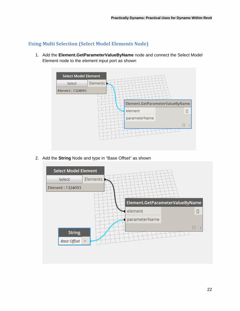
1. Add the Element.GetParameterValueByName node and connect the Select Model Element node to the element input port as shown
2. Add the String Node and type in “Base Offset” as shown
Practically Dynamo: Practical Uses for Dynamo Within Revit
23
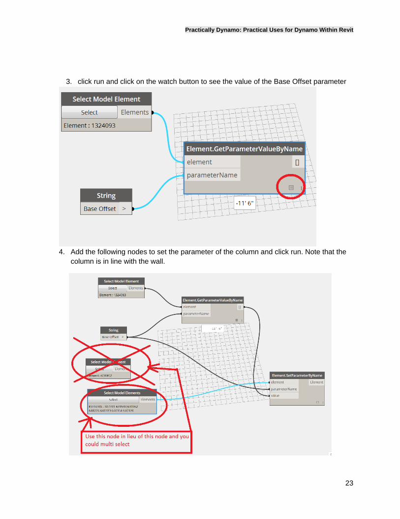
3. click run and click on the watch button to see the value of the Base Offset parameter
4. Add the following nodes to set the parameter of the column and click run. Note that the
column is in line with the wall.
Practically Dynamo: Practical Uses for Dynamo Within Revit
24
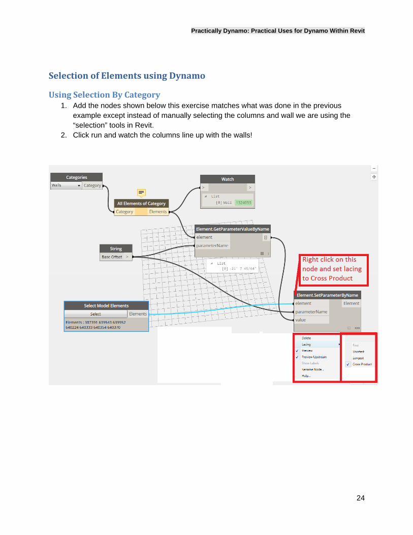
SelectionofElementsusingDynamo
UsingSelectionByCategory1. Add the nodes shown below this exercise matches what was done in the previous
example except instead of manually selecting the columns and wall we are using the “selection” tools in Revit.
2. Click run and watch the columns line up with the walls!
Practically Dynamo: Practical Uses for Dynamo Within Revit
25
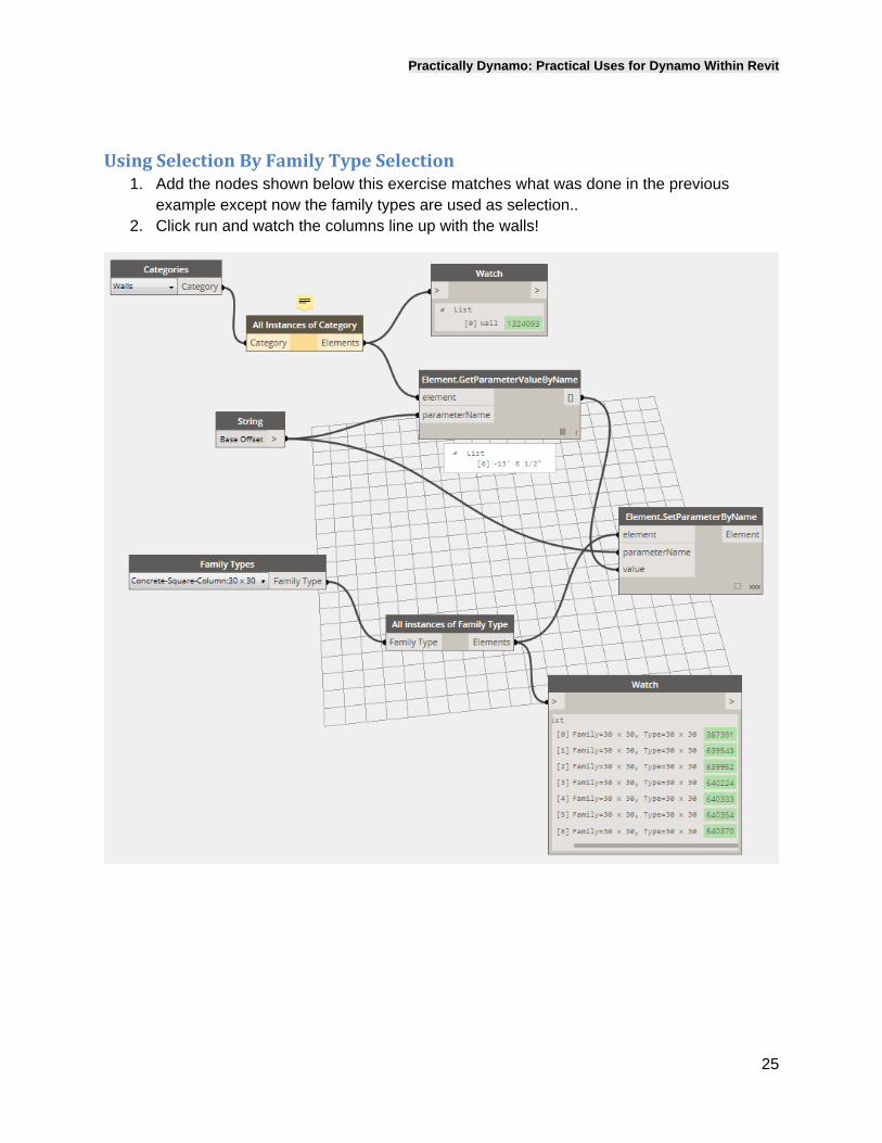
UsingSelectionByFamilyTypeSelection1. Add the nodes shown below this exercise matches what was done in the previous
example except now the family types are used as selection.. 2. Click run and watch the columns line up with the walls!
Practically Dynamo: Practical Uses for Dynamo Within Revit
26
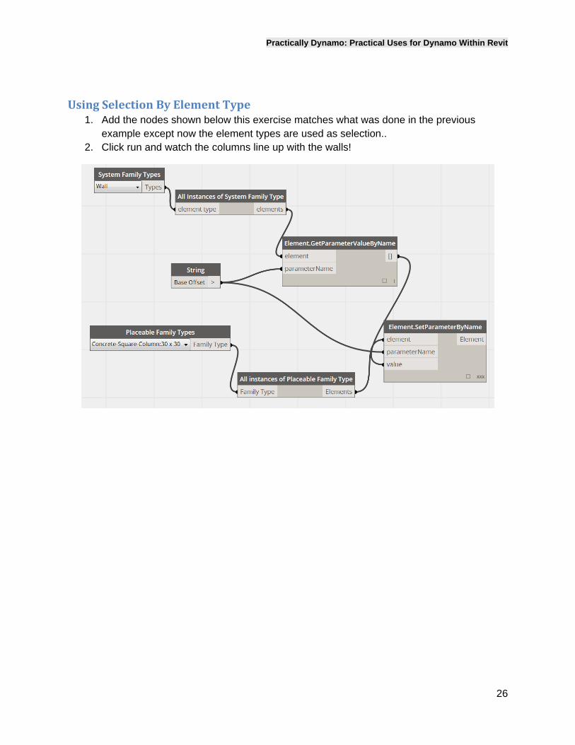
UsingSelectionByElementType1. Add the nodes shown below this exercise matches what was done in the previous
example except now the element types are used as selection.. 2. Click run and watch the columns line up with the walls!
Practically Dynamo: Practical Uses for Dynamo Within Revit
27
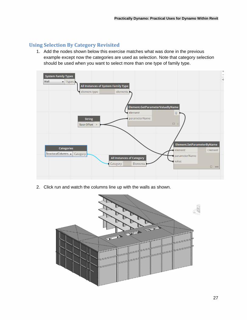
UsingSelectionByCategoryRevisited1. Add the nodes shown below this exercise matches what was done in the previous
example except now the categories are used as selection. Note that category selection should be used when you want to select more than one type of family type.
2. Click run and watch the columns line up with the walls as shown.
Practically Dynamo: Practical Uses for Dynamo Within Revit
28
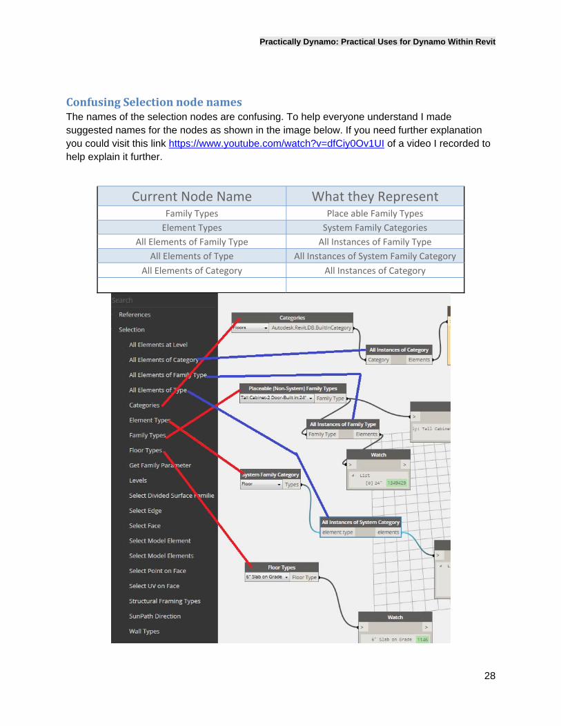
ConfusingSelectionnodenamesThe names of the selection nodes are confusing. To help everyone understand I made suggested names for the nodes as shown in the image below. If you need further explanation you could visit this link https://www.youtube.com/watch?v=dfCiy0Ov1UI of a video I recorded to help explain it further.
Current Node Name What they Represent Family Types Place able Family Types
Element Types System Family Categories
All Elements of Family Type All Instances of Family Type
All Elements of Type All Instances of System Family Category
All Elements of Category All Instances of Category
Practically Dynamo: Practical Uses for Dynamo Within Revit
29
Profileorder
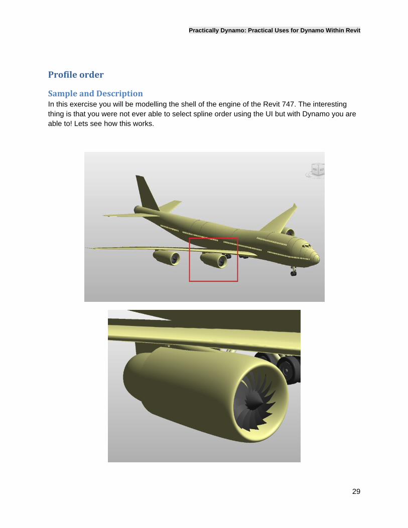
SampleandDescriptionIn this exercise you will be modelling the shell of the engine of the Revit 747. The interesting thing is that you were not ever able to select spline order using the UI but with Dynamo you are able to! Lets see how this works.
Practically Dynamo: Practical Uses for Dynamo Within Revit
30
SplineOrder
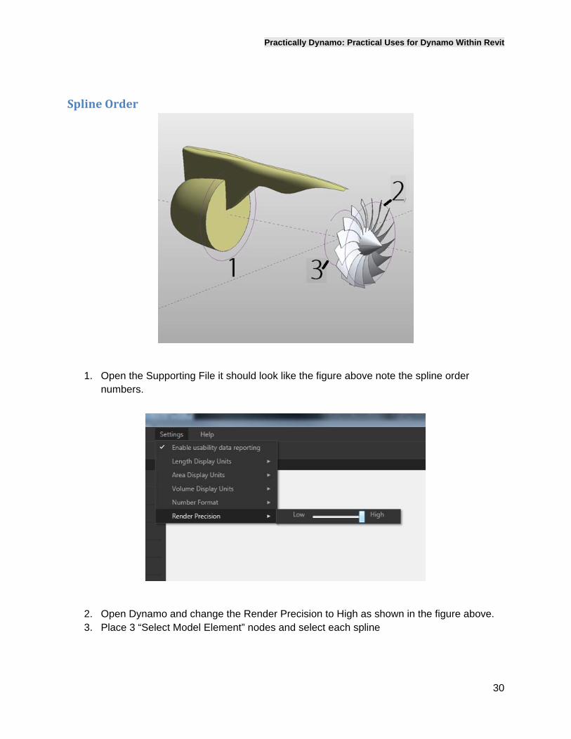
1. Open the Supporting File it should look like the figure above note the spline order
numbers.
2. Open Dynamo and change the Render Precision to High as shown in the figure above. 3. Place 3 “Select Model Element” nodes and select each spline
Practically Dynamo: Practical Uses for Dynamo Within Revit
31
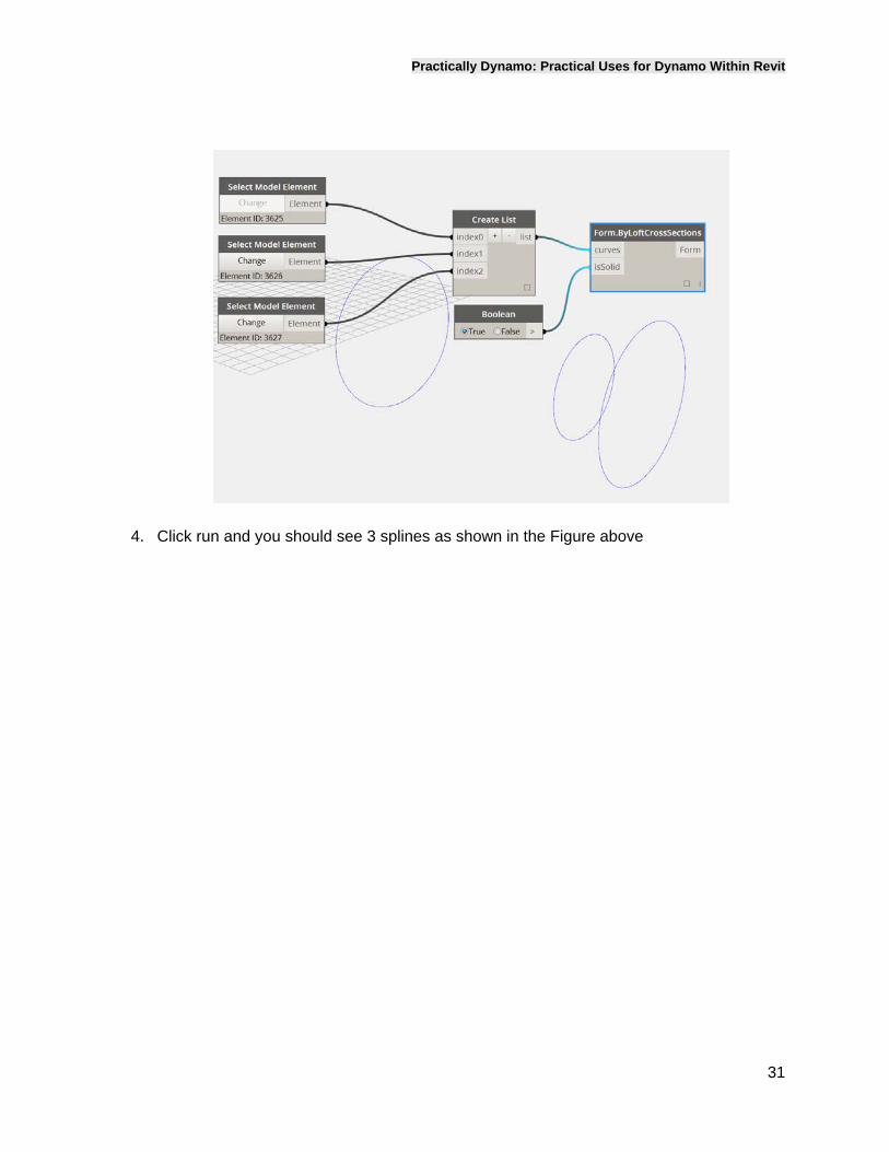
4. Click run and you should see 3 splines as shown in the Figure above
Practically Dynamo: Practical Uses for Dynamo Within Revit
32
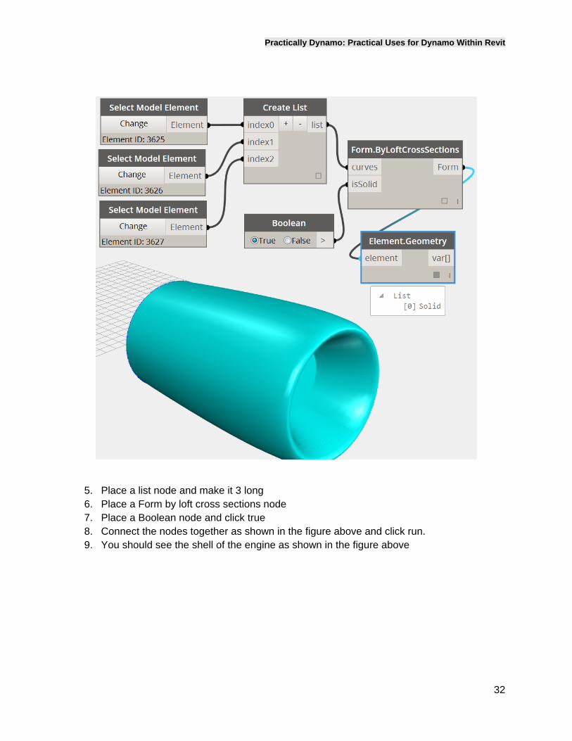
5. Place a list node and make it 3 long 6. Place a Form by loft cross sections node 7. Place a Boolean node and click true 8. Connect the nodes together as shown in the figure above and click run. 9. You should see the shell of the engine as shown in the figure above
Practically Dynamo: Practical Uses for Dynamo Within Revit
33
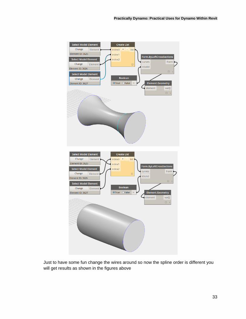
Just to have some fun change the wires around so now the spline order is different you will get results as shown in the figures above
Practically Dynamo: Practical Uses for Dynamo Within Revit
34
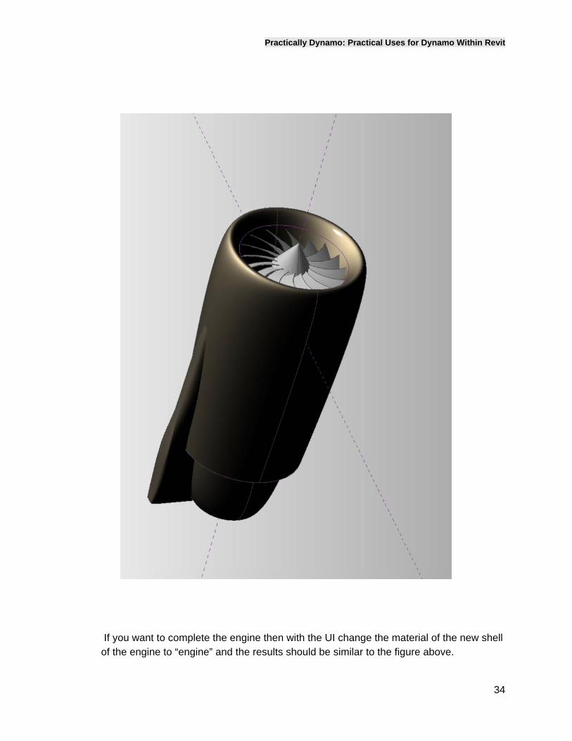
If you want to complete the engine then with the UI change the material of the new shell of the engine to “engine” and the results should be similar to the figure above.
Practically Dynamo: Practical Uses for Dynamo Within Revit
35
CanopyFraming
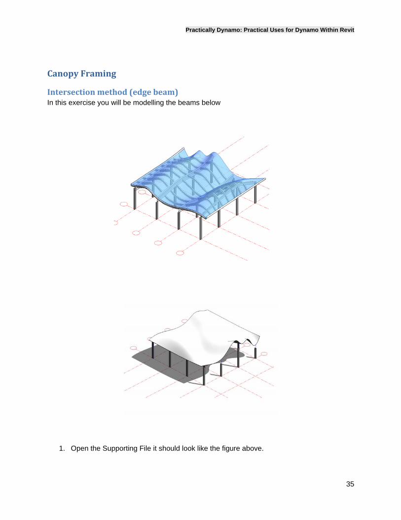
Intersectionmethod(edgebeam)In this exercise you will be modelling the beams below
1. Open the Supporting File it should look like the figure above.
Practically Dynamo: Practical Uses for Dynamo Within Revit
36
2.
3.
4.
5.
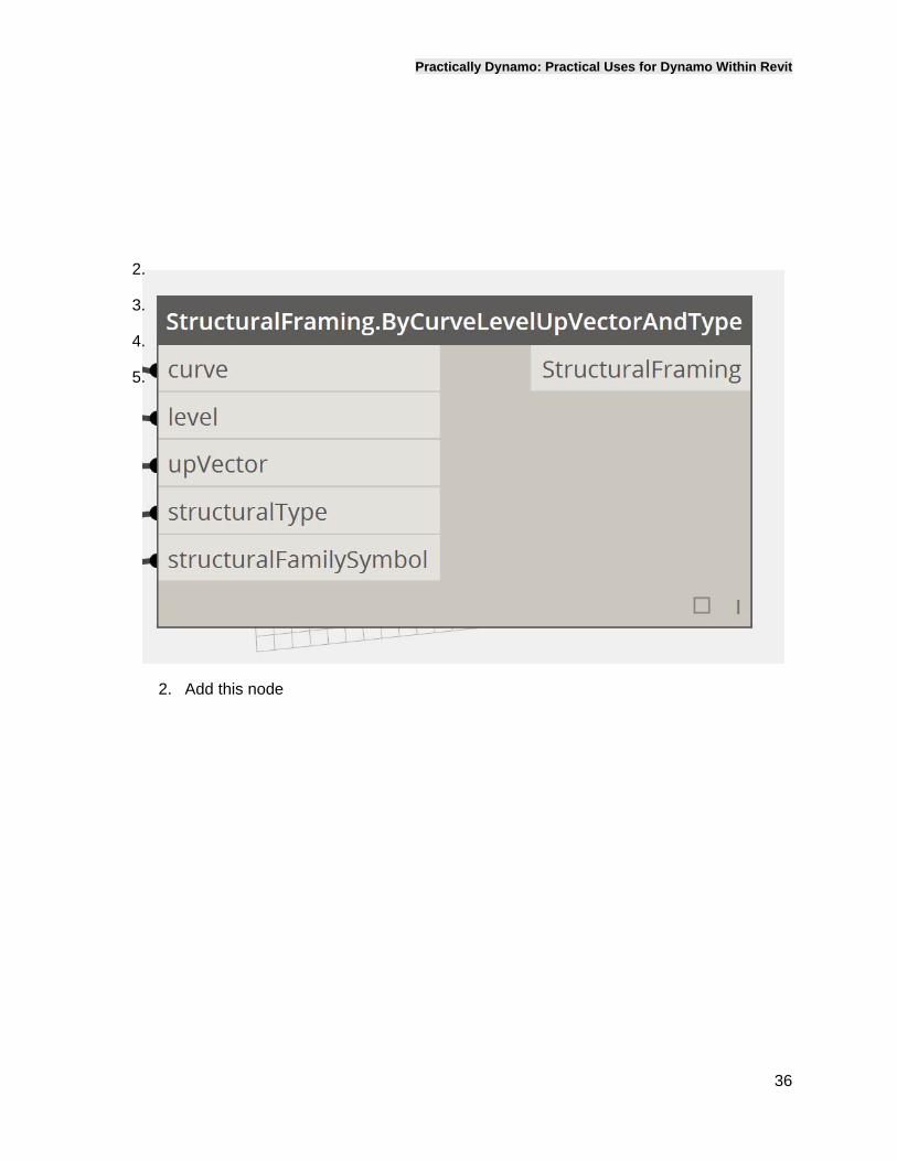
2. Add this node
Practically Dynamo: Practical Uses for Dynamo Within Revit
37
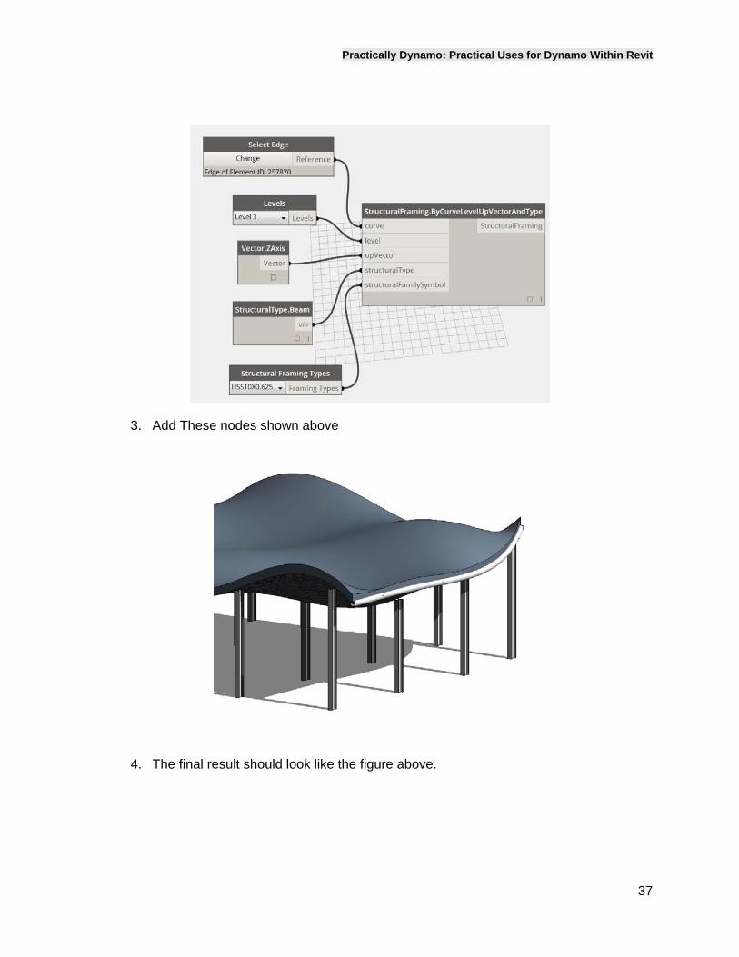
3. Add These nodes shown above
4. The final result should look like the figure above.
Practically Dynamo: Practical Uses for Dynamo Within Revit
38
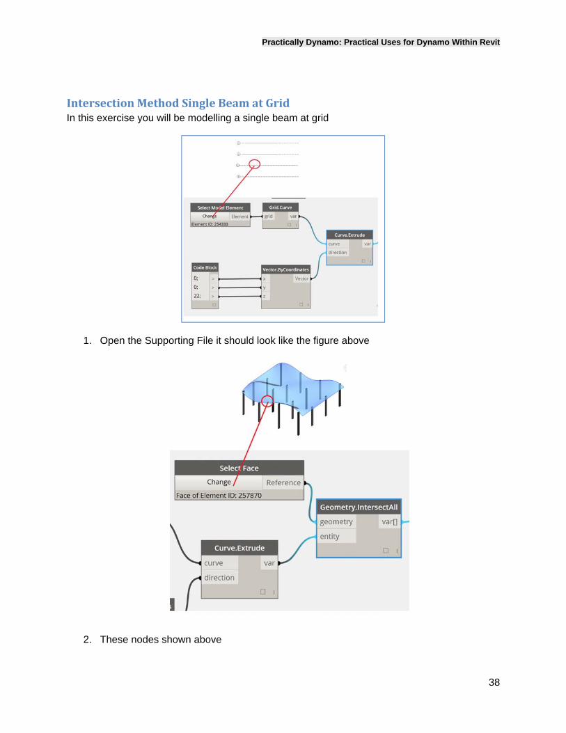
IntersectionMethodSingleBeamatGridIn this exercise you will be modelling a single beam at grid
1. Open the Supporting File it should look like the figure above
2. These nodes shown above
Practically Dynamo: Practical Uses for Dynamo Within Revit
39
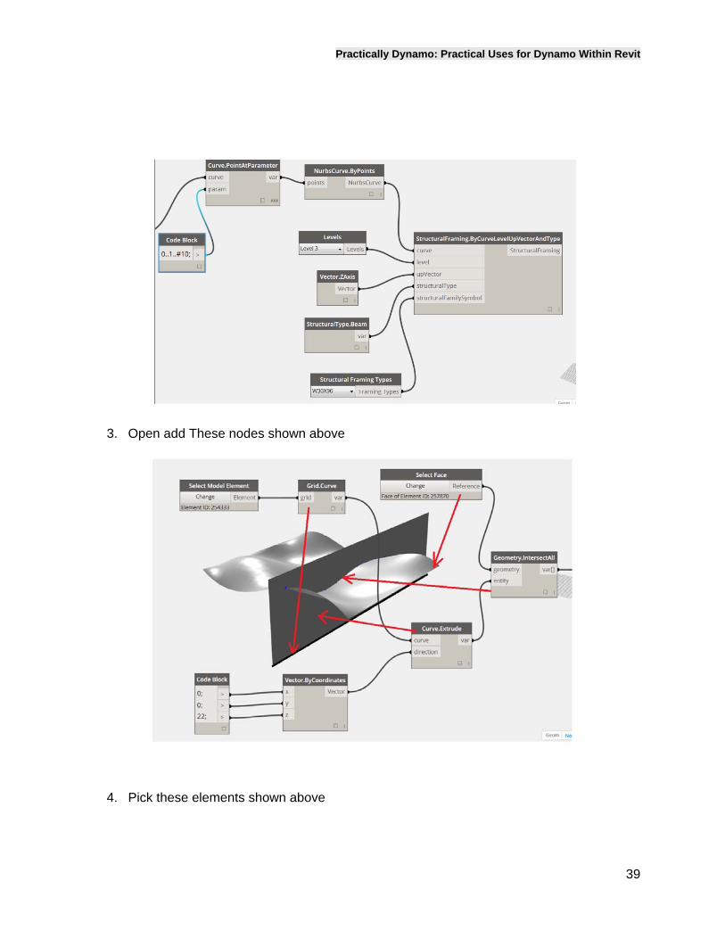
3. Open add These nodes shown above
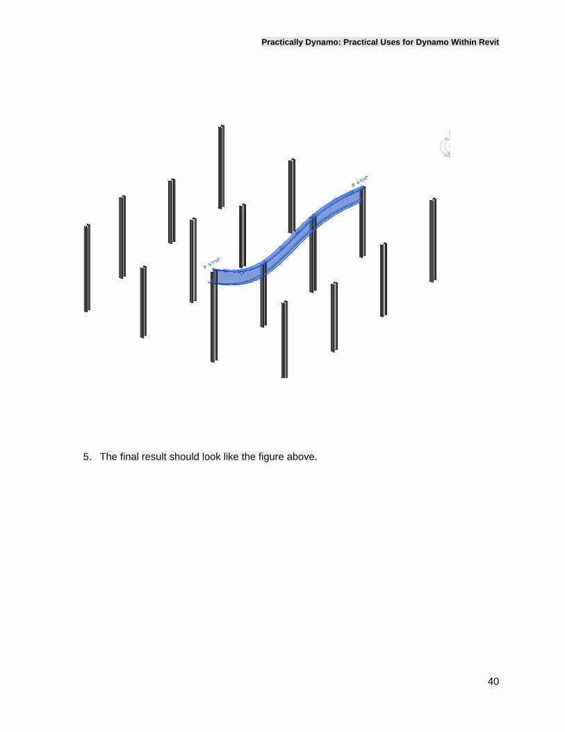
4. Pick these elements shown above
Practically Dynamo: Practical Uses for Dynamo Within Revit
40
5. The final result should look like the figure above.
Practically Dynamo: Practical Uses for Dynamo Within Revit
41
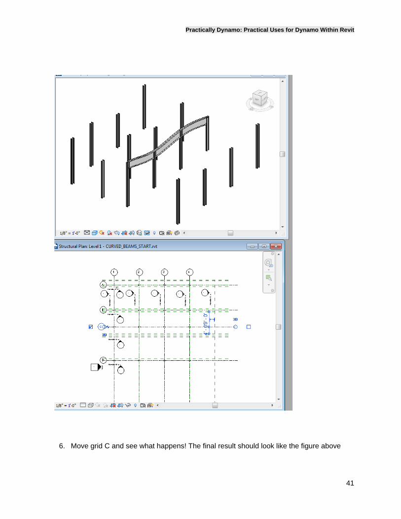
6. Move grid C and see what happens! The final result should look like the figure above
Practically Dynamo: Practical Uses for Dynamo Within Revit
42
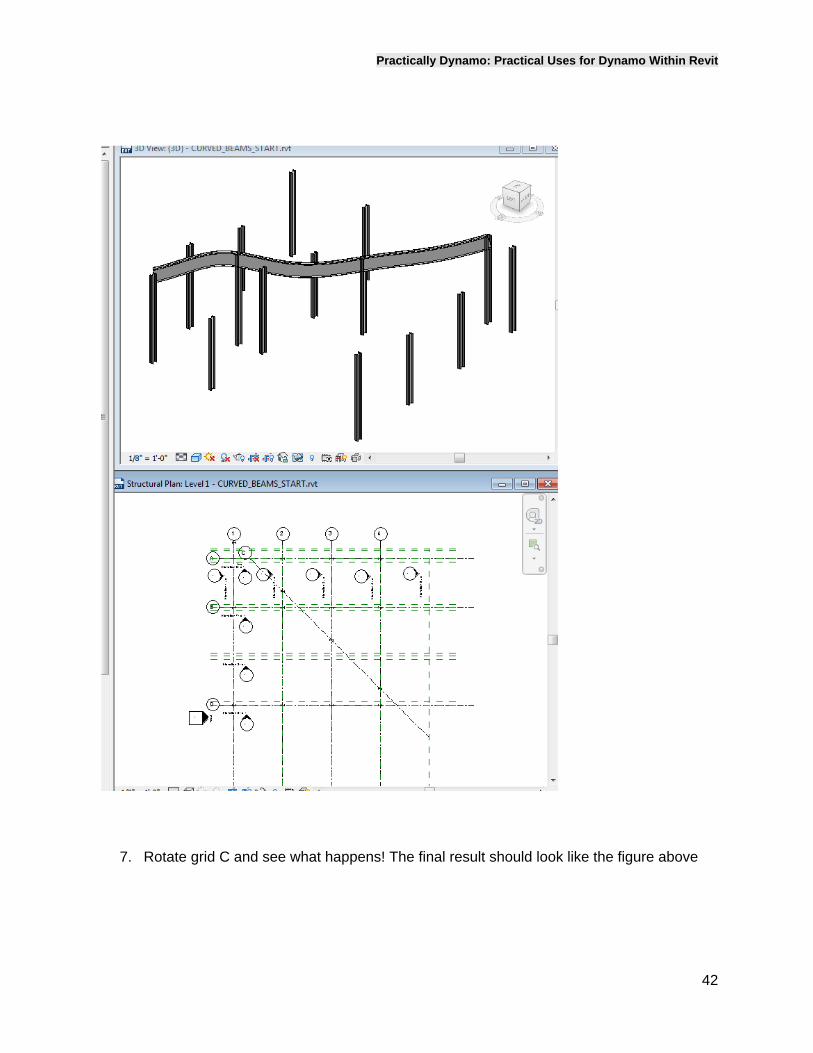
7. Rotate grid C and see what happens! The final result should look like the figure above
Practically Dynamo: Practical Uses for Dynamo Within Revit
43
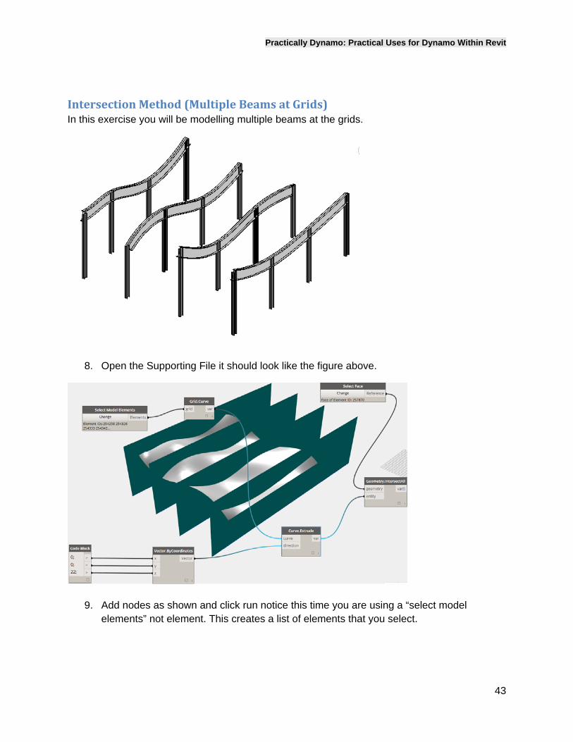
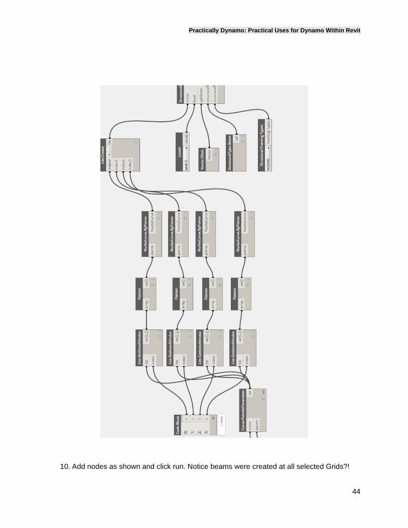
IntersectionMethod(MultipleBeamsatGrids)In this exercise you will be modelling multiple beams at the grids.
8. Open the Supporting File it should look like the figure above.
9. Add nodes as shown and click run notice this time you are using a “select model elements” not element. This creates a list of elements that you select.
Practically Dynamo: Practical Uses for Dynamo Within Revit
44
10. Add nodes as shown and click run. Notice beams were created at all selected Grids?!
Practically Dynamo: Practical Uses for Dynamo Within Revit
45
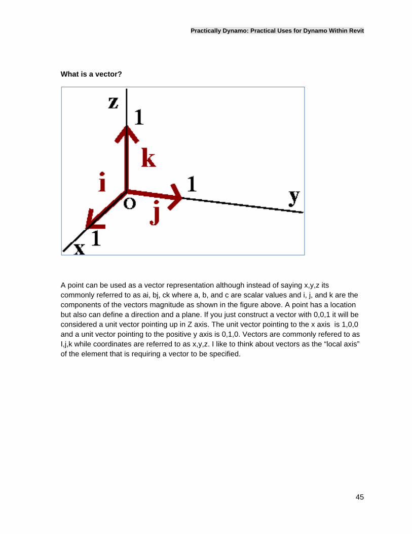
What is a vector?
A point can be used as a vector representation although instead of saying x,y,z its commonly referred to as ai, bj, ck where a, b, and c are scalar values and i, j, and k are the components of the vectors magnitude as shown in the figure above. A point has a location but also can define a direction and a plane. If you just construct a vector with 0,0,1 it will be considered a unit vector pointing up in Z axis. The unit vector pointing to the x axis is 1,0,0 and a unit vector pointing to the positive y axis is 0,1,0. Vectors are commonly refered to as I,j,k while coordinates are referred to as x,y,z. I like to think about vectors as the “local axis” of the element that is requiring a vector to be specified.
Practically Dynamo: Practical Uses for Dynamo Within Revit
46
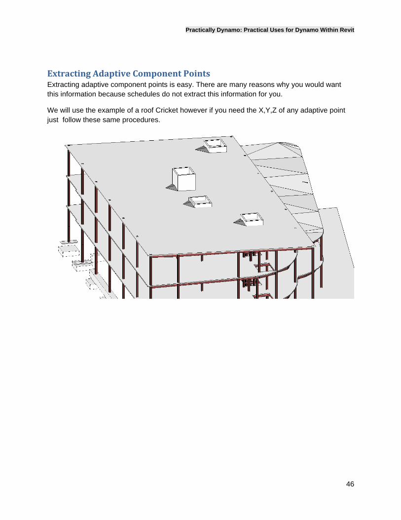
ExtractingAdaptiveComponentPointsExtracting adaptive component points is easy. There are many reasons why you would want this information because schedules do not extract this information for you.
We will use the example of a roof Cricket however if you need the X,Y,Z of any adaptive point just follow these same procedures.
Practically Dynamo: Practical Uses for Dynamo Within Revit
47
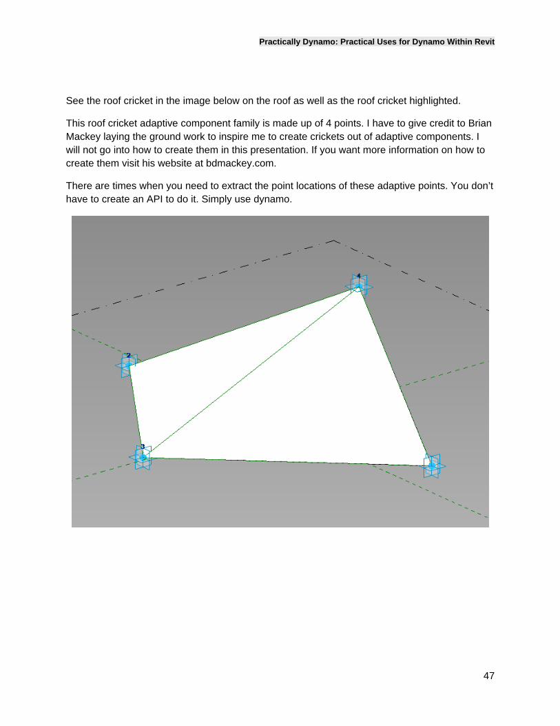
See the roof cricket in the image below on the roof as well as the roof cricket highlighted.
This roof cricket adaptive component family is made up of 4 points. I have to give credit to Brian Mackey laying the ground work to inspire me to create crickets out of adaptive components. I will not go into how to create them in this presentation. If you want more information on how to create them visit his website at bdmackey.com.
There are times when you need to extract the point locations of these adaptive points. You don’t have to create an API to do it. Simply use dynamo.
Practically Dynamo: Practical Uses for Dynamo Within Revit
48
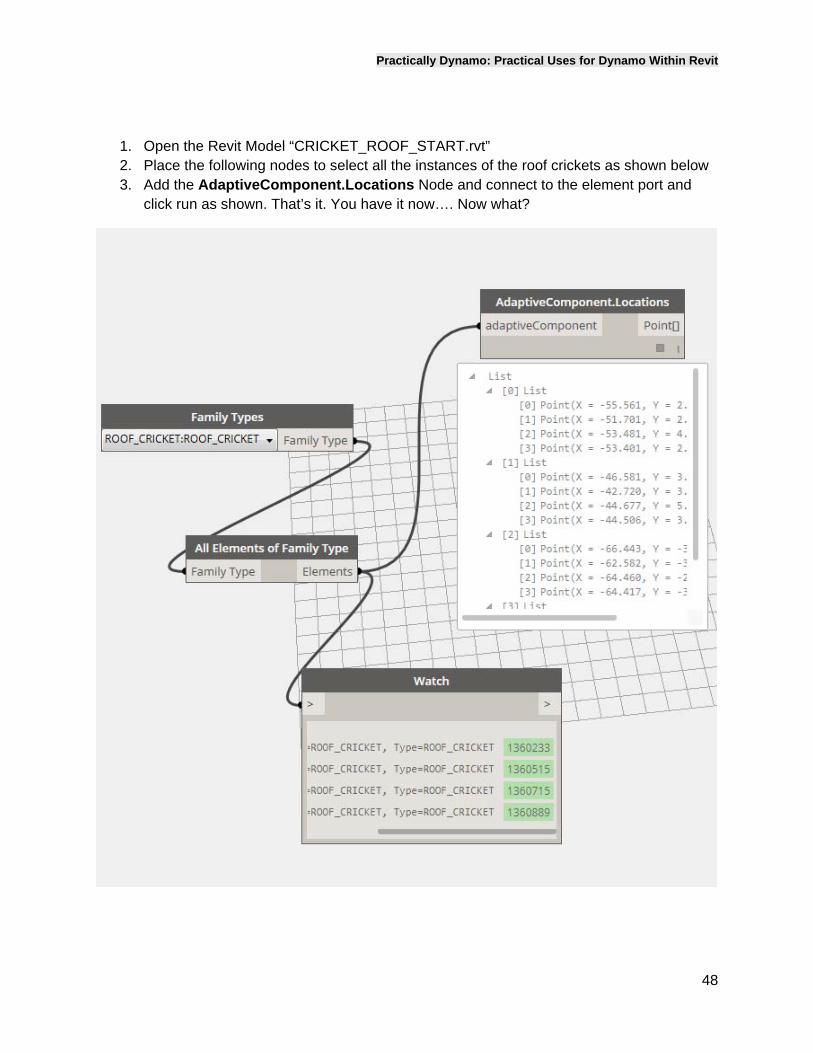
1. Open the Revit Model “CRICKET_ROOF_START.rvt” 2. Place the following nodes to select all the instances of the roof crickets as shown below 3. Add the AdaptiveComponent.Locations Node and connect to the element port and
click run as shown. That’s it. You have it now…. Now what?
Practically Dynamo: Practical Uses for Dynamo Within Revit
49
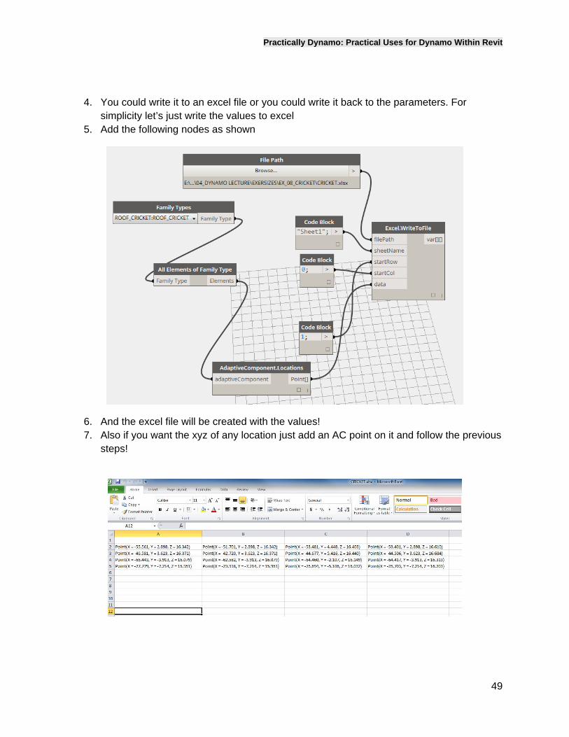
4. You could write it to an excel file or you could write it back to the parameters. For simplicity let’s just write the values to excel
5. Add the following nodes as shown
6. And the excel file will be created with the values! 7. Also if you want the xyz of any location just add an AC point on it and follow the previous
steps!
Practically Dynamo: Practical Uses for Dynamo Within Revit
50
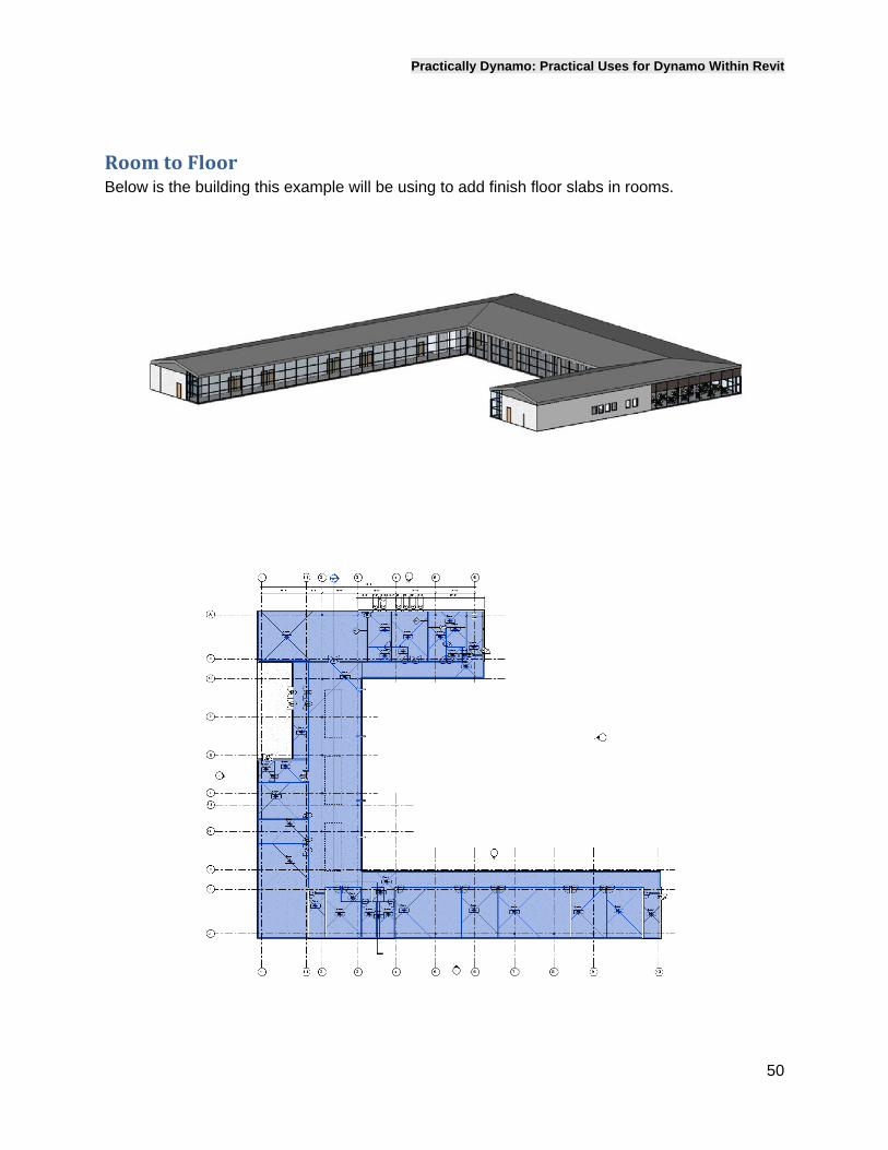
RoomtoFloorBelow is the building this example will be using to add finish floor slabs in rooms.
Practically Dynamo: Practical Uses for Dynamo Within Revit
51
Workflow
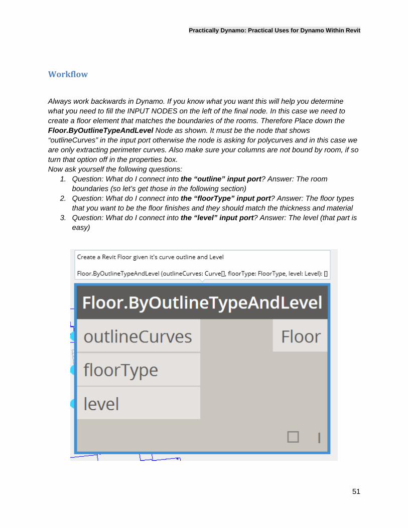
Always work backwards in Dynamo. If you know what you want this will help you determine what you need to fill the INPUT NODES on the left of the final node. In this case we need to create a floor element that matches the boundaries of the rooms. Therefore Place down the Floor.ByOutlineTypeAndLevel Node as shown. It must be the node that shows “outlineCurves” in the input port otherwise the node is asking for polycurves and in this case we are only extracting perimeter curves. Also make sure your columns are not bound by room, if so turn that option off in the properties box. Now ask yourself the following questions:
1. Question: What do I connect into the “outline” input port? Answer: The room boundaries (so let’s get those in the following section)
2. Question: What do I connect into the “floorType” input port? Answer: The floor types that you want to be the floor finishes and they should match the thickness and material
3. Question: What do I connect into the “level” input port? Answer: The level (that part is easy)
Practically Dynamo: Practical Uses for Dynamo Within Revit
52
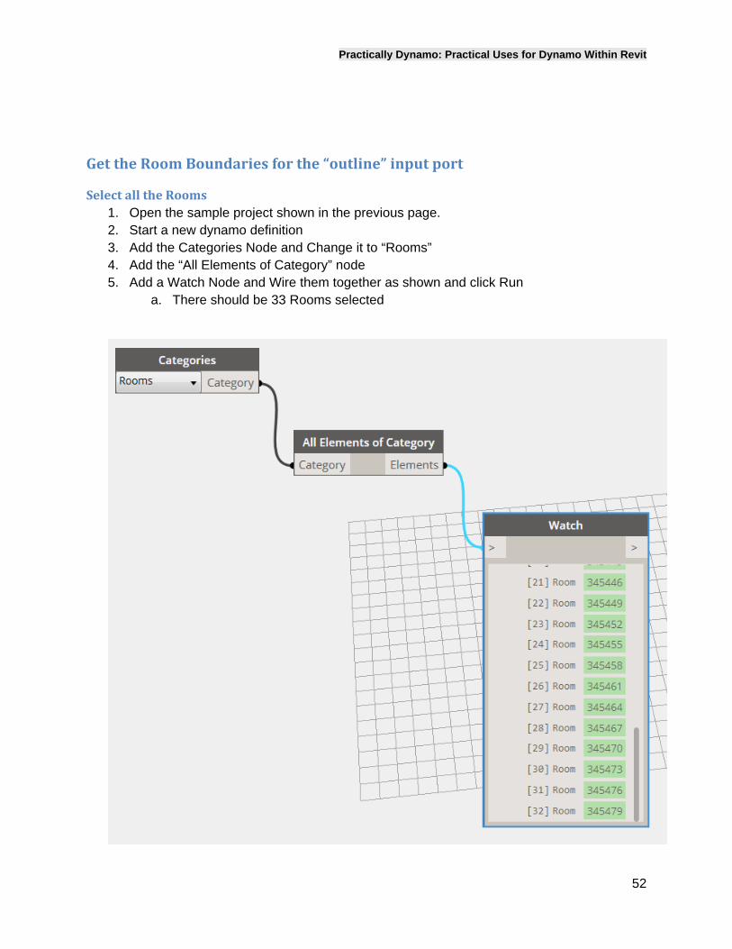
GettheRoomBoundariesforthe“outline”inputport
SelectalltheRooms1. Open the sample project shown in the previous page. 2. Start a new dynamo definition 3. Add the Categories Node and Change it to “Rooms” 4. Add the “All Elements of Category” node 5. Add a Watch Node and Wire them together as shown and click Run
a. There should be 33 Rooms selected
Practically Dynamo: Practical Uses for Dynamo Within Revit
53
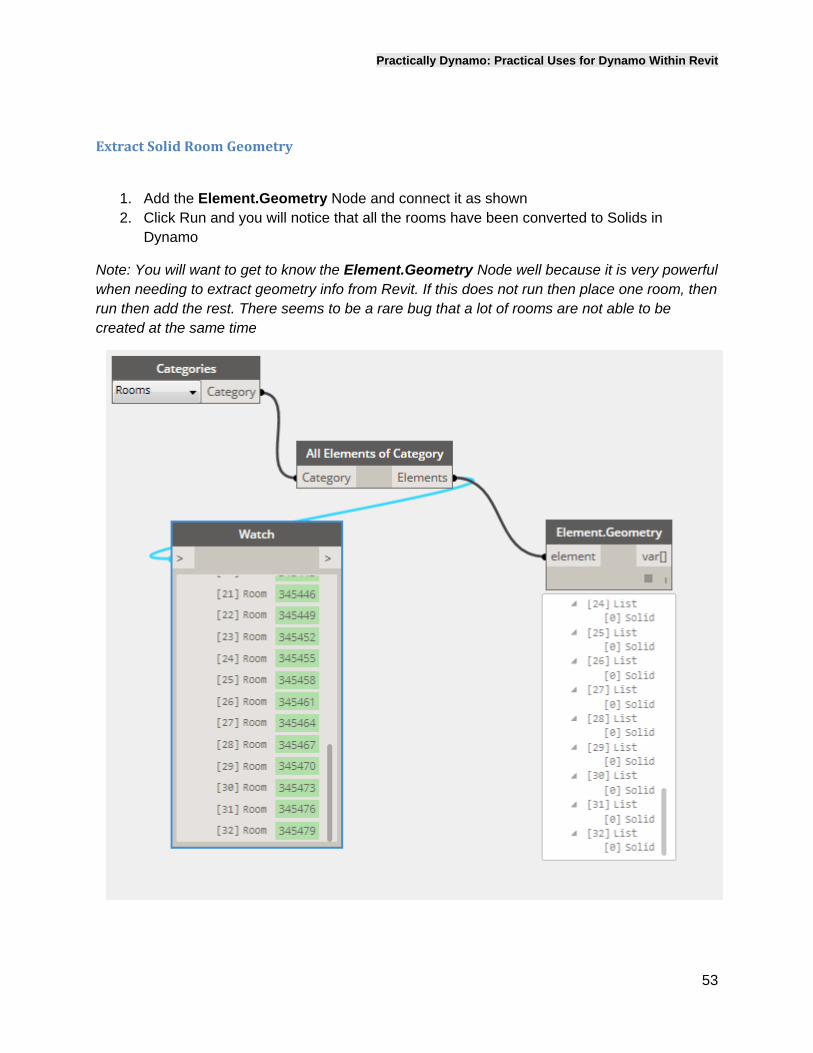
ExtractSolidRoomGeometry
1. Add the Element.Geometry Node and connect it as shown 2. Click Run and you will notice that all the rooms have been converted to Solids in
Dynamo
Note: You will want to get to know the Element.Geometry Node well because it is very powerful when needing to extract geometry info from Revit. If this does not run then place one room, then run then add the rest. There seems to be a rare bug that a lot of rooms are not able to be created at the same time
Practically Dynamo: Practical Uses for Dynamo Within Revit
54
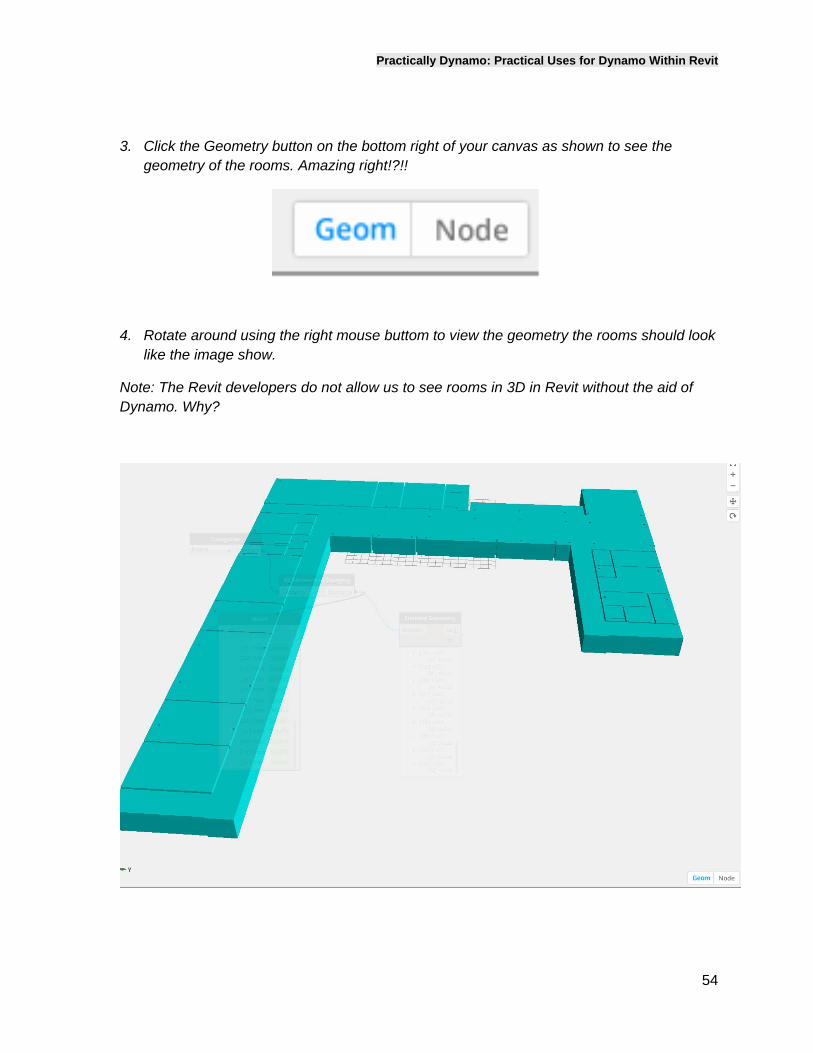
3. Click the Geometry button on the bottom right of your canvas as shown to see the geometry of the rooms. Amazing right!?!!
4. Rotate around using the right mouse buttom to view the geometry the rooms should look like the image show.
Note: The Revit developers do not allow us to see rooms in 3D in Revit without the aid of Dynamo. Why?
Practically Dynamo: Practical Uses for Dynamo Within Revit
55
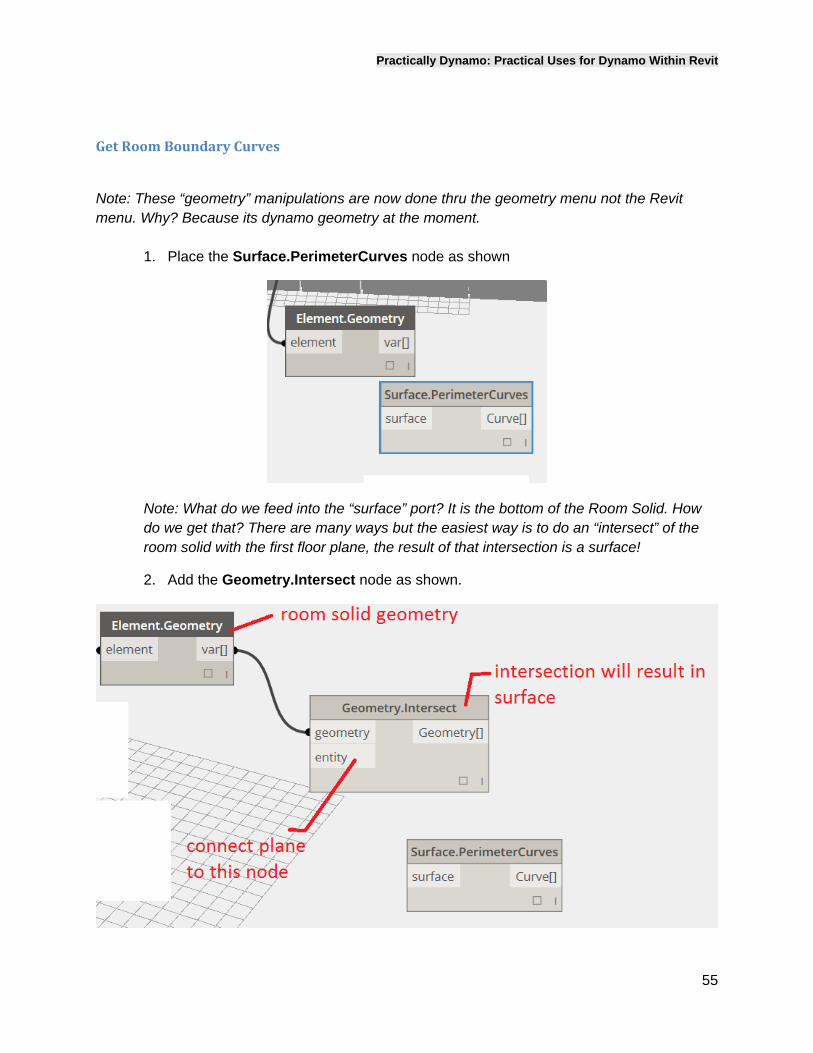
GetRoomBoundaryCurves
Note: These “geometry” manipulations are now done thru the geometry menu not the Revit menu. Why? Because its dynamo geometry at the moment.
1. Place the Surface.PerimeterCurves node as shown
Note: What do we feed into the “surface” port? It is the bottom of the Room Solid. How do we get that? There are many ways but the easiest way is to do an “intersect” of the room solid with the first floor plane, the result of that intersection is a surface!
2. Add the Geometry.Intersect node as shown.
Practically Dynamo: Practical Uses for Dynamo Within Revit
56
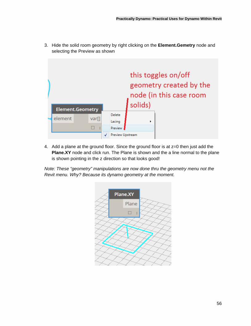
3. Hide the solid room geometry by right clicking on the Element.Gemetry node and selecting the Preview as shown
4. Add a plane at the ground floor. Since the ground floor is at z=0 then just add the Plane.XY node and click run. The Plane is shown and the a line normal to the plane is shown pointing in the z direction so that looks good!
Note: These “geometry” manipulations are now done thru the geometry menu not the Revit menu. Why? Because its dynamo geometry at the moment.
Practically Dynamo: Practical Uses for Dynamo Within Revit
57
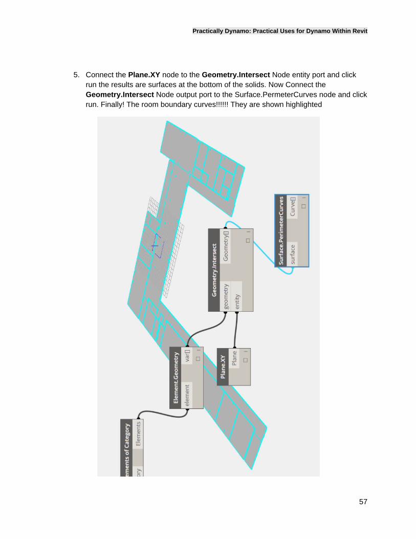
5. Connect the Plane.XY node to the Geometry.Intersect Node entity port and click run the results are surfaces at the bottom of the solids. Now Connect the Geometry.Intersect Node output port to the Surface.PermeterCurves node and click run. Finally! The room boundary curves!!!!!! They are shown highlighted
Practically Dynamo: Practical Uses for Dynamo Within Revit
58
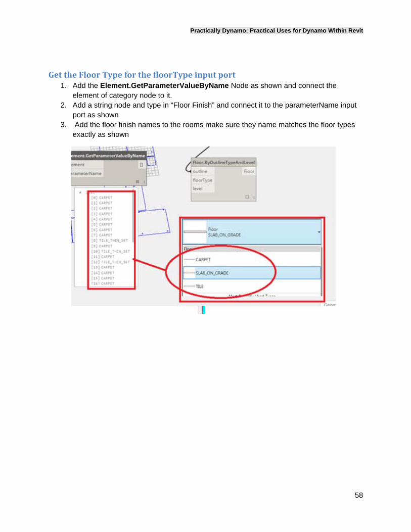
GettheFloorTypeforthefloorTypeinputport1. Add the Element.GetParameterValueByName Node as shown and connect the
element of category node to it. 2. Add a string node and type in “Floor Finish” and connect it to the parameterName input
port as shown 3. Add the floor finish names to the rooms make sure they name matches the floor types
exactly as shown
Practically Dynamo: Practical Uses for Dynamo Within Revit
59
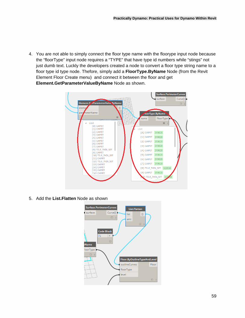
4. You are not able to simply connect the floor type name with the floorype input node because the “floorType” input node requires a “TYPE” that have type id numbers while “stings” not just dumb text. Luckly the developers created a node to convert a floor type string name to a floor type id type node. Thefore, simply add a FloorType.ByName Node (from the Revit Element Floor Create menu) and connect it between the floor and get Element.GetParameterValueByName Node as shown.
5. Add the List.Flatten Node as shown
Practically Dynamo: Practical Uses for Dynamo Within Revit
60
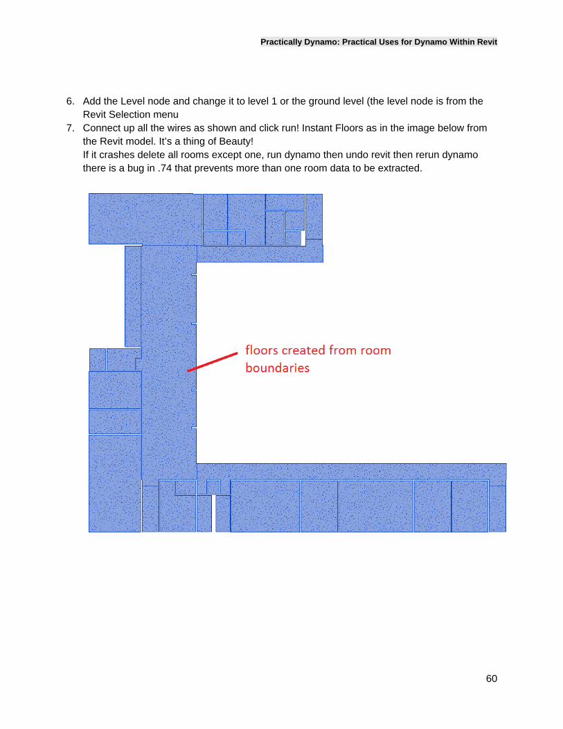
6. Add the Level node and change it to level 1 or the ground level (the level node is from the Revit Selection menu
7. Connect up all the wires as shown and click run! Instant Floors as in the image below from the Revit model. It’s a thing of Beauty! If it crashes delete all rooms except one, run dynamo then undo revit then rerun dynamo there is a bug in .74 that prevents more than one room data to be extracted.
Practically Dynamo: Practical Uses for Dynamo Within Revit
61
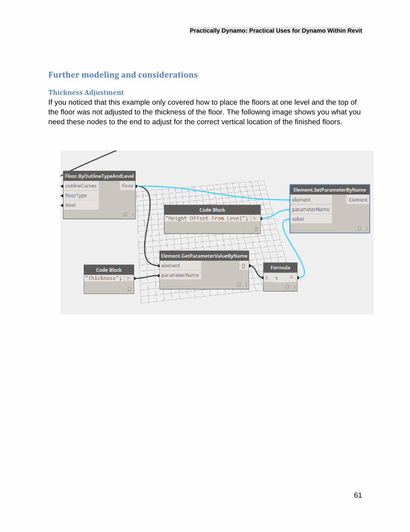
Furthermodelingandconsiderations
ThicknessAdjustmentIf you noticed that this example only covered how to place the floors at one level and the top of the floor was not adjusted to the thickness of the floor. The following image shows you what you need these nodes to the end to adjust for the correct vertical location of the finished floors.
Practically Dynamo: Practical Uses for Dynamo Within Revit
62
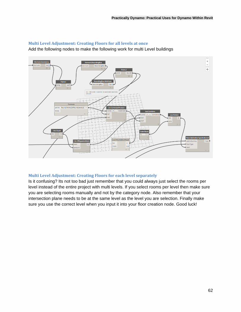
MultiLevelAdjustment:CreatingFloorsforalllevelsatonceAdd the following nodes to make the following work for multi Level buildings
MultiLevelAdjustment:CreatingFloorsforeachlevelseparatelyIs it confusing? Its not too bad just remember that you could always just select the rooms per level instead of the entire project with multi levels. If you select rooms per level then make sure you are selecting rooms manually and not by the category node. Also remember that your intersection plane needs to be at the same level as the level you are selection. Finally make sure you use the correct level when you input it into your floor creation node. Good luck!
Practically Dynamo: Practical Uses for Dynamo Within Revit
63
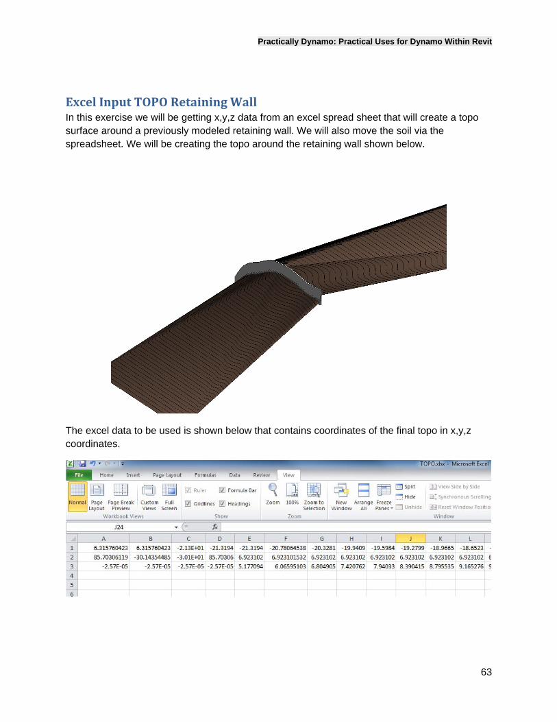
ExcelInputTOPORetainingWallIn this exercise we will be getting x,y,z data from an excel spread sheet that will create a topo surface around a previously modeled retaining wall. We will also move the soil via the spreadsheet. We will be creating the topo around the retaining wall shown below.
The excel data to be used is shown below that contains coordinates of the final topo in x,y,z coordinates.
Practically Dynamo: Practical Uses for Dynamo Within Revit
64
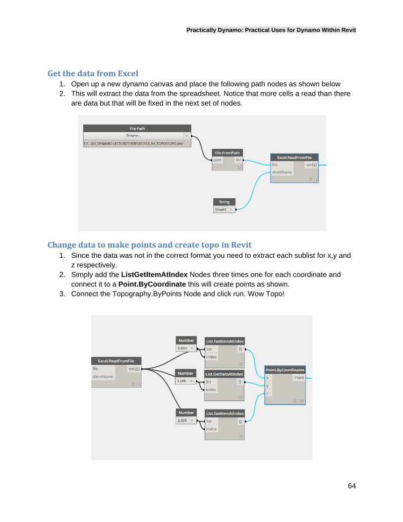
GetthedatafromExcel1. Open up a new dynamo canvas and place the following path nodes as shown below 2. This will extract the data from the spreadsheet. Notice that more cells a read than there
are data but that will be fixed in the next set of nodes.
ChangedatatomakepointsandcreatetopoinRevit1. Since the data was not in the correct format you need to extract each sublist for x,y and
z respectively. 2. Simply add the ListGetItemAtIndex Nodes three times one for each coordinate and
connect it to a Point.ByCoordinate this will create points as shown. 3. Connect the Topography.ByPoints Node and click run. Wow Topo!
Practically Dynamo: Practical Uses for Dynamo Within Revit
65
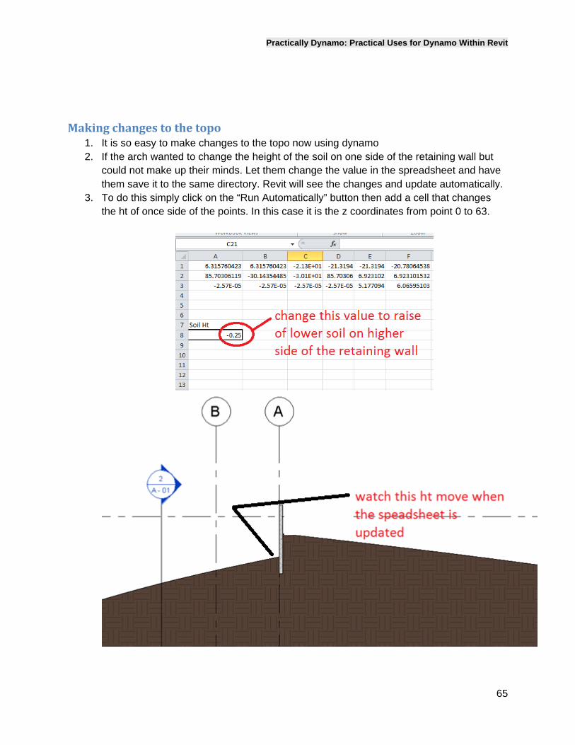
Makingchangestothetopo1. It is so easy to make changes to the topo now using dynamo 2. If the arch wanted to change the height of the soil on one side of the retaining wall but
could not make up their minds. Let them change the value in the spreadsheet and have them save it to the same directory. Revit will see the changes and update automatically.
3. To do this simply click on the “Run Automatically” button then add a cell that changes the ht of once side of the points. In this case it is the z coordinates from point 0 to 63.
Practically Dynamo: Practical Uses for Dynamo Within Revit
66
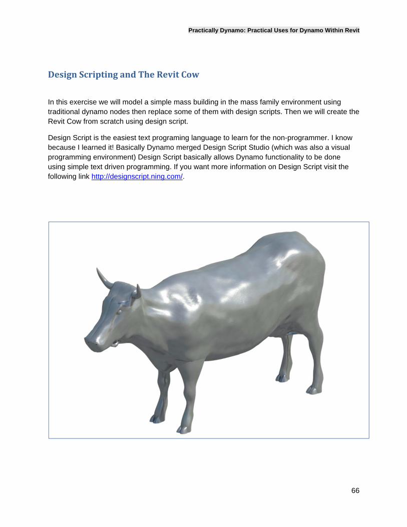
DesignScriptingandTheRevitCow
In this exercise we will model a simple mass building in the mass family environment using traditional dynamo nodes then replace some of them with design scripts. Then we will create the Revit Cow from scratch using design script.
Design Script is the easiest text programing language to learn for the non-programmer. I know because I learned it! Basically Dynamo merged Design Script Studio (which was also a visual programming environment) Design Script basically allows Dynamo functionality to be done using simple text driven programming. If you want more information on Design Script visit the following link http://designscript.ning.com/.
Practically Dynamo: Practical Uses for Dynamo Within Revit
67
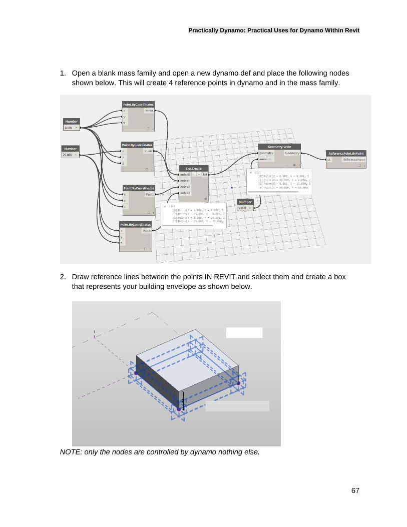
1. Open a blank mass family and open a new dynamo def and place the following nodes shown below. This will create 4 reference points in dynamo and in the mass family.
2. Draw reference lines between the points IN REVIT and select them and create a box that represents your building envelope as shown below.
NOTE: only the nodes are controlled by dynamo nothing else.
Practically Dynamo: Practical Uses for Dynamo Within Revit
68
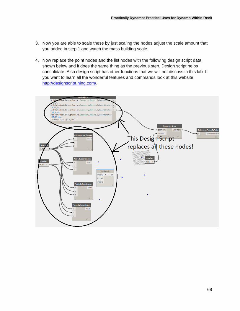
3. Now you are able to scale these by just scaling the nodes adjust the scale amount that you added in step 1 and watch the mass building scale.
4. Now replace the point nodes and the list nodes with the following design script data shown below and it does the same thing as the previous step. Design script helps consolidate. Also design script has other functions that we will not discuss in this lab. If you want to learn all the wonderful features and commands look at this website http://designscript.ning.com/.
Practically Dynamo: Practical Uses for Dynamo Within Revit
69
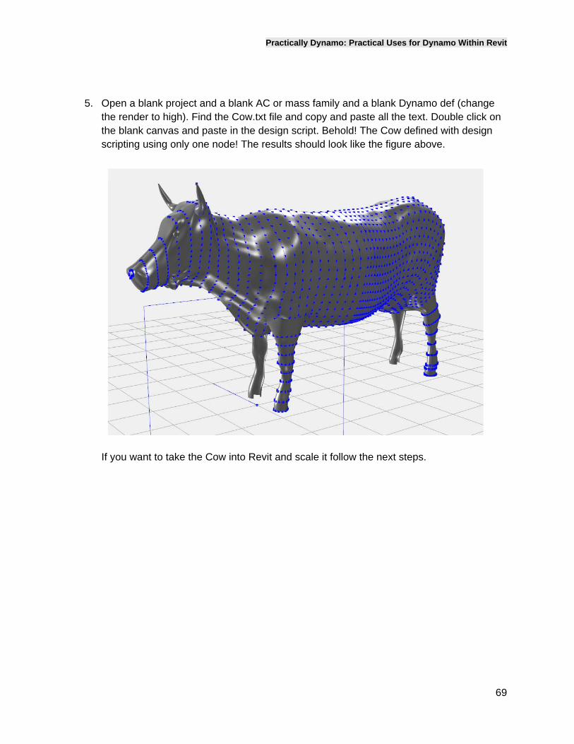
5. Open a blank project and a blank AC or mass family and a blank Dynamo def (change the render to high). Find the Cow.txt file and copy and paste all the text. Double click on the blank canvas and paste in the design script. Behold! The Cow defined with design scripting using only one node! The results should look like the figure above.
If you want to take the Cow into Revit and scale it follow the next steps.
Practically Dynamo: Practical Uses for Dynamo Within Revit
70
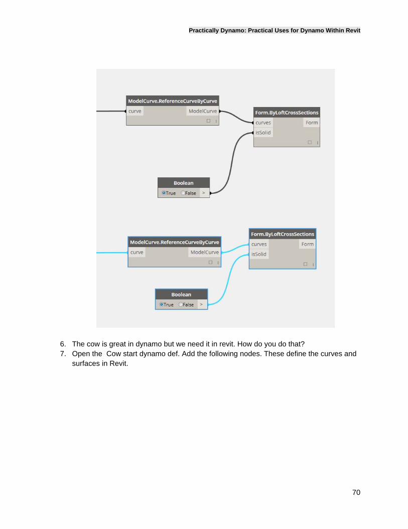
6. The cow is great in dynamo but we need it in revit. How do you do that? 7. Open the Cow start dynamo def. Add the following nodes. These define the curves and
surfaces in Revit.
Practically Dynamo: Practical Uses for Dynamo Within Revit
71
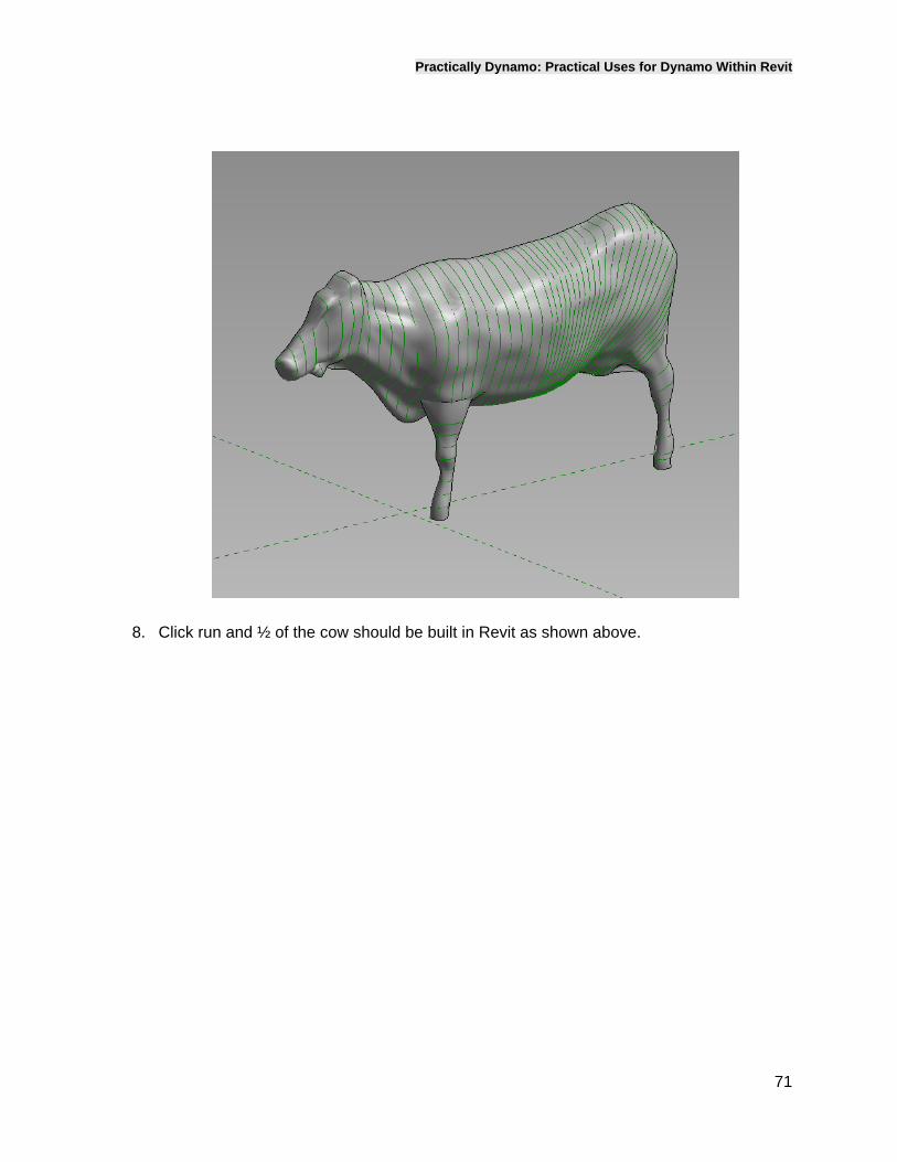
8. Click run and ½ of the cow should be built in Revit as shown above.
Practically Dynamo: Practical Uses for Dynamo Within Revit
72
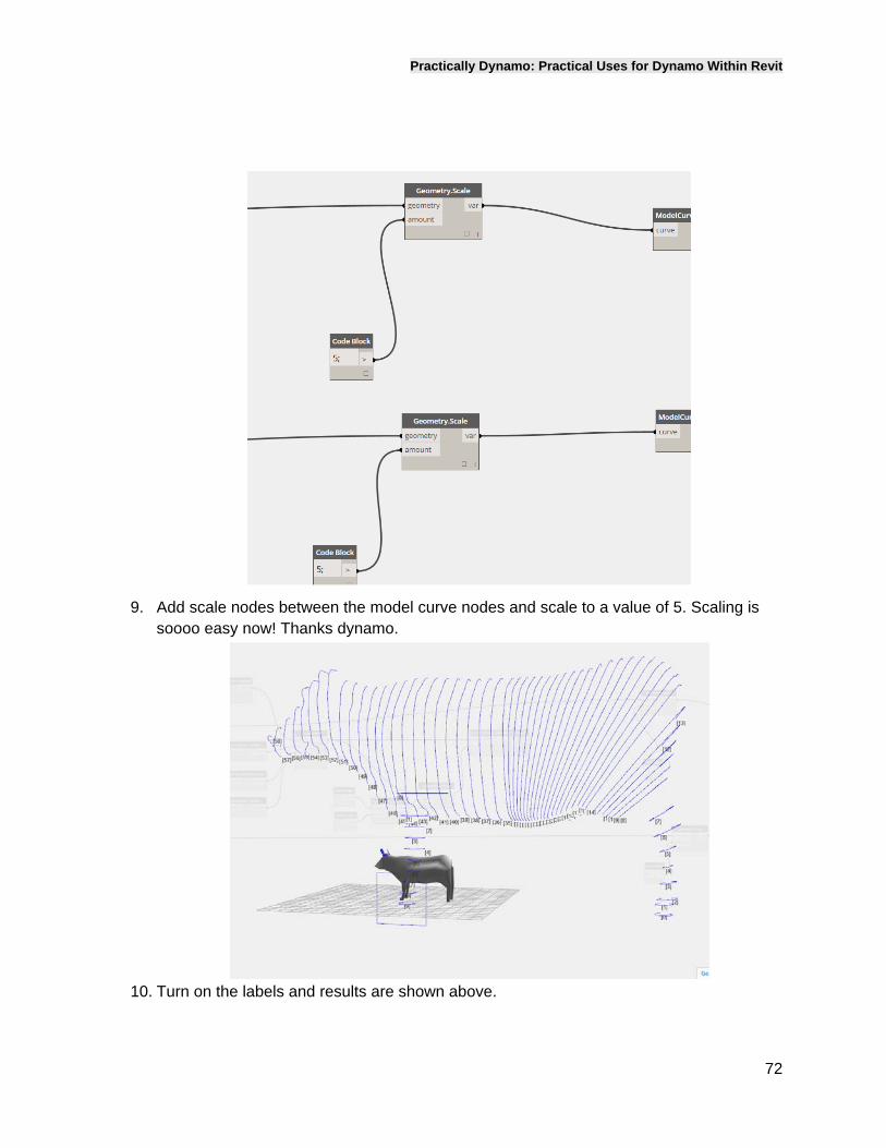
9. Add scale nodes between the model curve nodes and scale to a value of 5. Scaling is
soooo easy now! Thanks dynamo.
10. Turn on the labels and results are shown above.
Practically Dynamo: Practical Uses for Dynamo Within Revit
73
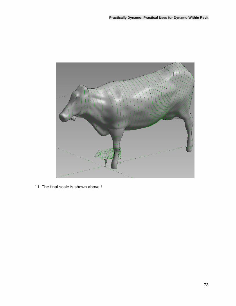
11. The final scale is shown above.!