attention ! ! ! modification of cables requires
TRANSCRIPT

MODIFICATION OF CABLES Rev 2.0 Data: 05/2016
MODIFICATION OF C12, C13, C14, C18, C19 CABLES
C12, C13, C14, C18, C19 cables require additional bridge in DB25 connector between PINS 9 and 22
C12 CABLE C13 CABLE CABLE C14 CABLE C18 CABLE C19
C12, C13, C14, C18, C19 CABLES AFTER MODIFICATION CHART - C12, C13, C14, C18, C19 CABLES AFTER MODIFICATION
Measuring clip DB25 in cables C12, C13,C14
DB25 CONNECTOR C18 C19
1 12 12 Black Brown 2 11 11 White Black 3 10 10 Green Green 4 5 5 Brown White 5 4 4 Blue ------------- 6 2 2 Yellow Yellow 7 25 25 ------------- Blue 8 9 9 Red Red
BRIDGE 9+22 BRIDGE 9+22 9+22
! ! ! ATTENTION ! ! ! MODIFICATION OF CABLES REQUIRES: SCREWDRIVER, SOLDERING IRON, TIN

MODIFICATION OF CABLES Rev 2.0 Data: 05/2016
MODIFICATION OF C6 CABLE
C6 Cable requires additional installation in DB25 connector:
PIN CABLE 12 WHITE 19 WHITE
COAXIAL 21 BLACK (SHIELD)
C6 CABLE
! ! ! ATTENTION ! ! ! COAXIAL CABLE LENGTH 32 cm
C6 CABLE AFTER MODIFICATION
CHART - C6 CABLE AFTER MODIFICATION
DB 25 CONNECTOR C6 Cable 14 Black alligator 13 Red alligator 8 Blue 9 Brown
10 Yellow (via 10Ω resistor) 12 White 19 White COAXIAL 21 Black (SHIELD)
Coaxial and white cables should be unsoldered from H1 cable (DP3)
H1 CABLE WILL NOT BE USED IN DIAGPROG4
MODIFICATION OF CABLES Rev 2.0 Data: 05/2016
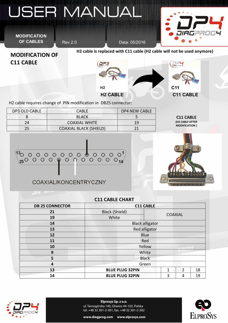
MODIFICATION OF C11 CABLE
H2 cable requires change of PIN modification in DB25 connector:
DP3 OLD CABLE CABLE DP4 NEW CABLE 8 BLACK 5
24 COAXIAL WHITE 19 25 COAXIAL BLACK (SHIELD) 21
H2 CABLE C11 CABLE
H2 cable is replaced with C11 cable (H2 cable will not be used anymore)
C11 CABLE (H2 CABLE AFTER MODIFICATION )
C11 CABLE CHART DB 25 CONNECTOR C11 CABLE
21 Black (Shield) COAXIAL 19 White 14 Black alligator 13 Red alligator 12 Blue 11 Red 10 Yellow 9 White 5 Black 4 Green
13 BLUE PLUG 32PIN 1 2 18 14 BLUE PLUG 32PIN 3 4 19
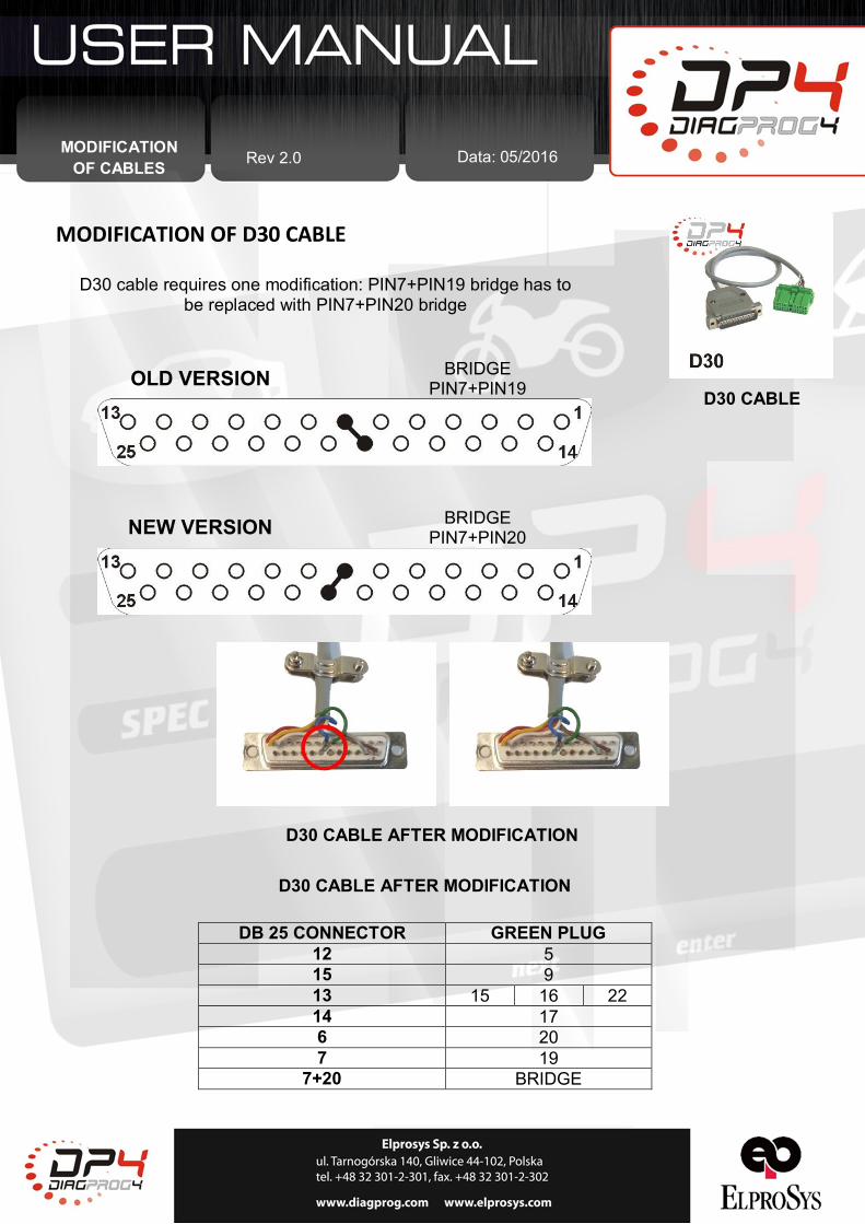
MODIFICATION OF D30 CABLE
MODIFICATION OF CABLES Rev 2.0 Data: 05/2016
D30 cable requires one modification: PIN7+PIN19 bridge has to be replaced with PIN7+PIN20 bridge
D30 CABLE OLD VERSION BRIDGE
PIN7+PIN19
NEW VERSION BRIDGE PIN7+PIN20
D30 CABLE AFTER MODIFICATION
D30 CABLE AFTER MODIFICATION
DB 25 CONNECTOR GREEN PLUG 12 5 15 9 13 15 16 22 14 17 6 20 7 19
7+20 BRIDGE
MODIFICATION OF CABLES Data: 05/2016 Rev 2.0
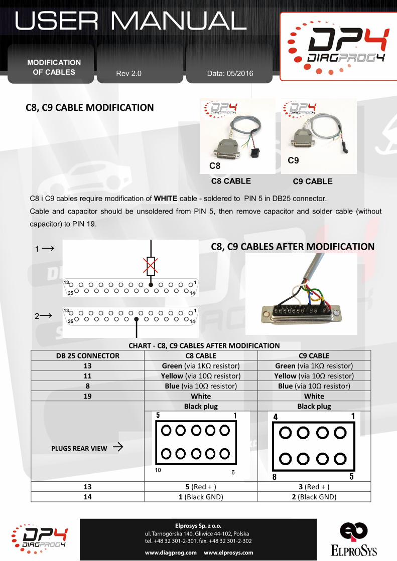
C8, C9 CABLE MODIFICATION
C8 CABLE C9 CABLE
C8 i C9 cables require modification of WHITE cable - soldered to PIN 5 in DB25 connector.
Cable and capacitor should be unsoldered from PIN 5, then remove capacitor and solder cable (without
capacitor) to PIN 19.
1 →
2→
C8, C9 CABLES AFTER MODIFICATION
CHART - C8, C9 CABLES AFTER MODIFICATION DB 25 CONNECTOR C8 CABLE C9 CABLE
13 Green (via 1KΩ resistor) Green (via 1KΩ resistor) 11 Yellow (via 10Ω resistor) Yellow (via 10Ω resistor) 8 Blue (via 10Ω resistor) Blue (via 10Ω resistor)
19 White White Black plug Black plug
PLUGS REAR VIEW →
13 5 (Red + ) 3 (Red + ) 14 1 (Black GND) 2 (Black GND)
MODIFICATION OF CABLES Rev 2.0 Data: 05/2016
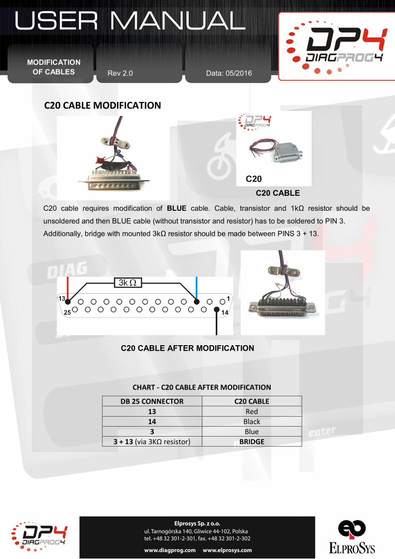
C20 CABLE MODIFICATION
C20 CABLE
C20 cable requires modification of BLUE cable. Cable, transistor and 1kΩ resistor should be
unsoldered and then BLUE cable (without transistor and resistor) has to be soldered to PIN 3.
Additionally, bridge with mounted 3kΩ resistor should be made between PINS 3 + 13.
C20 CABLE AFTER MODIFICATION
CHART - C20 CABLE AFTER MODIFICATION
DB 25 CONNECTOR C20 CABLE 13 Red 14 Black 3 Blue
3 + 13 (via 3KΩ resistor) BRIDGE

MODIFICATION OF CABLES Rev 2.0 Data: 05/2016
C22 CABLE MODIFICATION
C22 CABLE C22 cable requires modification of BLUE cable. Cable, transistor and 4,7kΩ resistor should be unsoldered and then BLUE cable (without transistor and resistor) has to be soldered to PIN 3.
C22 CABLE MODIFICATION
CHART – C22 CABLES AFTER MODIFICATION DB 25 CONNECTOR C22 CABLE
3 Blue 13 Red 13 Red 14 Yellow (via 330Ω resistor) 14 Brown 14 Black 15 Green 16 White
LEGAL DISCLAIMER It is forbidden to use DiagProg4 device, software for this device, information contained in this document and any other Elprosys products for purposes which are illegal or prohibited in any other way. Elprosys and the company’s management board shall not be liable for the results of the use of the DiagProg4 device, soft - ware, information contained in this document and any other Elprosys products for purposes which are illegal or prohibited in any other way. Copying, redistribu - tion, publishing, dissemination, sale, giving access to or making use in any other way of the whole or part of the software and data contained in this document are forbidden. Elprosys may introduce improvements or modifications of products on offer and their documentation as well instruction manuals at any time without a prior notice. Any and all trademarks, product names and information set forth in the document are the property of the Elprosys company and are protected by the law. A User is required to respect intellectual property rights of resources contained in the document.
C22 CABLE AFTER MODIFICATION