attachment 8 tank systems
TRANSCRIPT
Attachment 8 Tank Systems
Tank Systems, Revision 1 Site ID No. MID 980 615 298
TANK SYSTEMS
R 299.9615 and R 299.9627 of the administrative rules promulgated pursuant to Part 11 I, Hazardous Waste Management, of Michigan's Natural Resources and Environmental Protection Act, 1994 PA 451, as amended (Act 451); R 29.41 01 to R 29.4505 promulgated pursuant to the provisions of the Michigan Fire Protection Act, PA 207, as amended (Act 207); and Title 40 of the Code of Federal Regulations (CFR) §§270.14(d), 270.16, 270.24, and 270.27 (Part 264, Subpart J and Part 60, Appendix A) establish requirements for tank systems. All references to 40 CFR citations specified herein are adopted by reference in R 299.1 1003.
This license application template addresses requirements for tank systems at the Petro- Chem facility in ~ e 6 i t Michigan. This template includes assessments of new and existing tank systems; installation of new tank systems; secondary containment systems and release detection; variances for secondary containment; controls and practices to prevent spills and overfills; inspections; response to leaks or spills and disposition of leaking or unfit-for-use tank systems; closure and postclosure requirements; requirements for storing or treating ignitable, reactive, or incompatible wastes
This template is organized as follows:
[XI Existing Tank System
[XI New Tank System
TANK MANAGEMENT UNITS
Drawing Process 2 identifies the locations of the current Tank Management Units at the PCPG site. The areas included in the Tank Management Unit are:
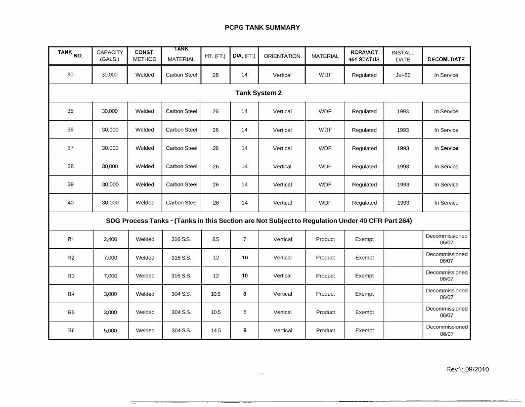
Tank System 1 (Formerly PCPG West Tank Farm) (1 6 - 30) Tank System 2 (Formerly SBS Tank Farm) (35 - 40) Tank System 3 (SDG Waste Storage Tank Farm) (61 - 72) CMB Tanks TK001, TKO02 all associated piping and containment devices.
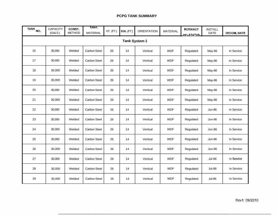
Appendix 1 of this template provides a listing of all tanks located at the site, including all regulated tanks and non-regulated tanks. All tanks and piping used by PCPG are located above ground. All tanks used for blending, and inbound are constructed of carbon steel or stainless steel. All tanks are grounded to prevent accumulation of static electricity generated during material transfers and carbon steel tanks are painted to reduce the potential for corrosion. The pH of the materials to be placed into each tank is determined and controlled as necessary to prevent corrosion. Materials used for construction of the tank systems are compatible with the materials accepted at the PCPG site. Tanks are placarded to comply with the requirements of NFPA 704, Identification of the Fire Hazards of Materials, 1990 Edition.
Inspection of all tanks at the PCPG site is carried out in accordance with 40 CFR 264.15 and includes tanks, containment units, and ancillary equipment. A copy of
Page 1 of 6

Tank Systems, Revision 1 Site ID No. MID 980 615 298
the inspection log is outlined in detail in the Inspection Section of this application. PCPG inspects all the tank systems daily to detect corrosion or the release of
waste, as well as areas immediately surrounding the externally accessible portion of the tank system, including secondary containment, to detect any release of hazardous wastes. Notations of the observations made are recorded along with the date, time, and name of the inspector. Spilled materials discovered during this inspection are cleaned up by pumping or absorption, and the area decontaminated using detergents and/or high pressure water spray. Collected spillage is treated onsite in the same method as the original material. Any deficiencies identified during the inspection are so noted in the inspection log along with the date and nature of the corrective action taken.
A tank farm inventory is taken daily and analysis performed on each tank as required (Inspection Plan, Tank Farm Reports)
A. Locations, Capacities and Details
The Tank Management Units subject to this application include the Tank System 1 (PCPG West Tank Farm); Tank System 2 (SBS Tank Farm), Tank System 3 (SDG Waste Storage Tank Farm) and CMB Tanks TKO01 & TK002.
B. Sequence of Bulk Handling Activities
1. Liquids Bulk tankers entering the Petro-Chem site are directed to a sampling and staging area. The manifest is inspected, contents of the tankers sampled, and sample analysis performed in accordance with the Waste Analysis Plan prior to the tanker being unloaded.
After any required analysis is complete and the shipment accepted as described in the Waste Analysis Plan, the driver is directed to one of the unloading areas.
At the unloading area, operations personnel connect discharge hoses and the vapor balance hose to the tanker and unload the tanker to the assigned storage or blending tank.
The operations personnel then secure the valves and disconnect the tank wagon's liquid and vapor return hoses that were used. The open ends of the lines are capped. Tank wagons will then be inspected and/or weighed at a truck scale to verify that the tank is empty. If significant amounts of the manifested quantity of the waste cannot be removed and remains inside the tank wagon, the generator is contacted and the discrepancy is handled using the procedures outlined in the Waste Analysis Plan.
2. Solids
Bulk solids received onsite in roll off containers may be directed to the staging and sampling area at the Site. Samples are obtained from the waste as described in the Waste Analysis Plan Section of this Application. Upon approval, the roll off container may be transferred to the unloading
bay in the SBS Building.
Page 2 of 6

Tank Systems, Revision 1 Site ID No. MID 980 615 298
Liquid waste suspension from the SBS, West & CMB Tank Farms are transferred to tankers for transportation to offsite licensed Hazardous Waste Boilers or Industrial Furnaces. Loading activities are conducted in the West PCPG and SBS LoadinglUnloading Pad using procedures identical to those described for liquid wastes.
C. Bulk Liquid LoadingIUnloading Areas
The PCPG site currently includes five loadinglunloading areas for receiving and shipping bulk liquid waste feed stocks, liquid and hazardous waste fuels,
The PCPG West & SBS LoadinglUnloading Pads for receipt and shipment of waste related materials. Each can accommodate up to 3 bulk tankers concurreritly.
All loadinglunloading areas at the PCPG site are designed with reinforced concrete pads and integral curbing to prevent run-off and to identify, contain, collect materials by pumping or absorption, and allow decontamination by use of detergents andlor high pressure water spray of any accidental release that may occur during .loading/unloading operation. Each loadinglunloading area is sufficiently impervious to prevent migration of contaminants to the surroundings.
1. The West LoadinglUnloading Pad (associated with the PCPG West Tank Farm) includes a double sloped lined concrete pad with a center collection sump. All piping and ancillary equipment, including filters, are included within the concrete containment. This pad also has a canopy to reduce entry of precipitation.
The SBS Loading Pad is located adjoining the SBS Tank Farm to the south. Containment is provided by a monolithically poured microsilicate concrete, with a central collection trough. Additional containment volume is provided by channels into the SBS Tank Farm. Up to two Tank Wagons can use this area at one time. A canopy covers the top and the west side of this area to minimize infiltration of precipitation. Precipitation and spillage is collected by portable pump or by vacuum loading truck as described below.
Explosion-proof pumps are used for transferring materials from bulk tankers in all areas. Bottom loadinglunloading of bulk tankers is normally utilized to minimize the threat of fire or explosion, and to facilitate the use of a vapor balance system. The vapor balance system associated with the East and West LoadingIUnloading Pad is employed for control of vapors from bulk loadinglunloading activities and is described later in the tank farm discussion. A static grounding system is also utilized within all areas to minimize the potential for fire.
Any materials or precipitation that accumulates on the pads are removed using portable pumps or a vacuum truck, or absorbed onto mops or absorbent. These collected run-on materials are currently either blended with the liquids in the fuels program or stored in the wastewater storage
Page 3 of 6
Tank Systems, Revision 1 Site ID No. MID 980 615 298
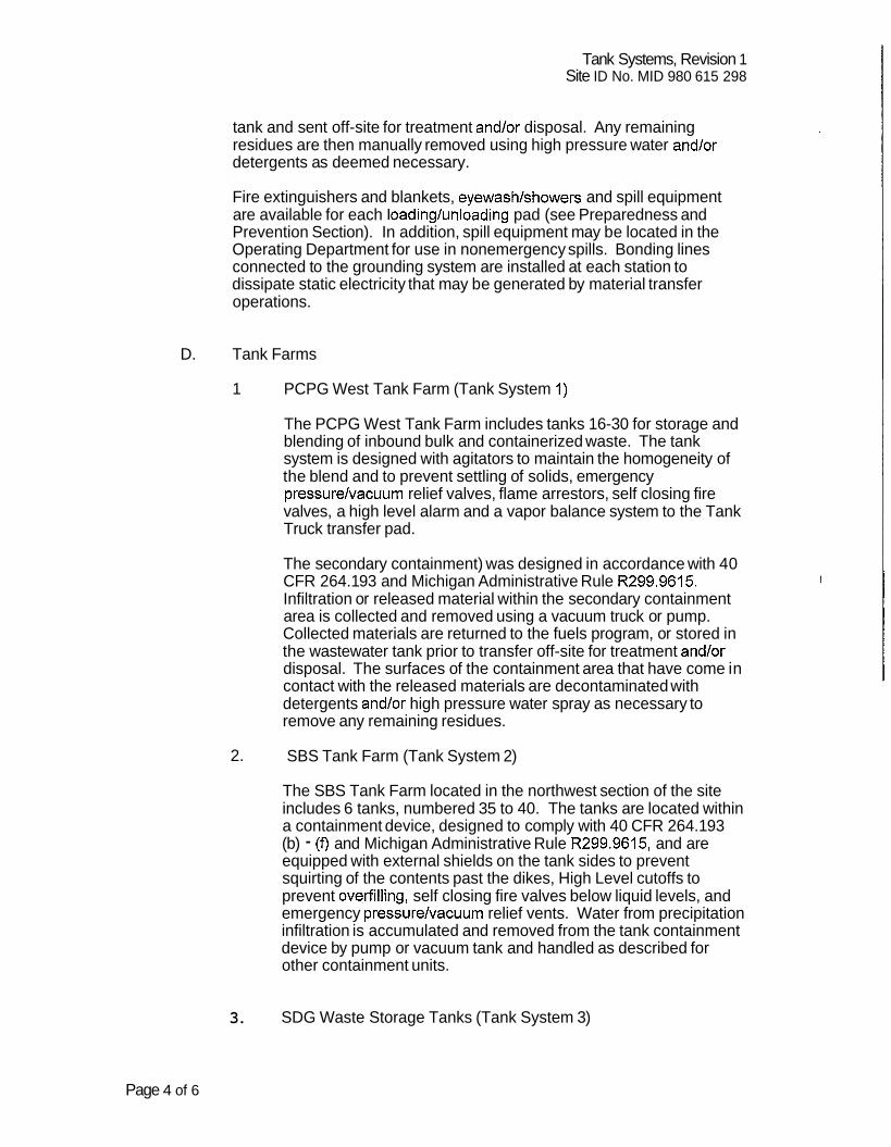
tank and sent off-site for treatment and/or disposal. Any remaining residues are then manually removed using high pressure water and/or detergents as deemed necessary.
Fire extinguishers and blankets, eyewash/showers and spill equipment are available for each loading/unloading pad (see Preparedness and Prevention Section). In addition, spill equipment may be located in the Operating Department for use in nonemergency spills. Bonding lines connected to the grounding system are installed at each station to dissipate static electricity that may be generated by material transfer operations.
D. Tank Farms
1 PCPG West Tank Farm (Tank System 1)
The PCPG West Tank Farm includes tanks 16-30 for storage and blending of inbound bulk and containerized waste. The tank system is designed with agitators to maintain the homogeneity of the blend and to prevent settling of solids, emergency pressure/vacuum relief valves, flame arrestors, self closing fire valves, a high level alarm and a vapor balance system to the Tank Truck transfer pad.
The secondary containment) was designed in accordance with 40 CFR 264.1 93 and Michigan Administrative Rule R299.9615. Infiltration or released material within the secondary containment area is collected and removed using a vacuum truck or pump. Collected materials are returned to the fuels program, or stored in the wastewater tank prior to transfer off-site for treatment and/or disposal. The surfaces of the containment area that have come in contact with the released materials are decontaminated with detergents and/or high pressure water spray as necessary to remove any remaining residues.
2. SBS Tank Farm (Tank System 2)
The SBS Tank Farm located in the northwest section of the site includes 6 tanks, numbered 35 to 40. The tanks are located within a containment device, designed to comply with 40 CFR 264.1 93 (b) - (f) and Michigan Administrative Rule R299.9615, and are equipped with external shields on the tank sides to prevent squirting of the contents past the dikes, High Level cutoffs to prevent ove,rfilling, self closing fire valves below liquid levels, and emergency pressure/vacuum relief vents. Water from precipitation infiltration is accumulated and removed from the tank containment device by pump or vacuum tank and handled as described for other containment units.
3. SDG Waste Storage Tanks (Tank System 3)
Page 4 of 6

Tank Systems, Revision 1 Site ID No. MID 980 615 298
This tank farm includes 12 inbound waste storage tanks (S61 - S72) located within a containment device, designed to comply with 40 CFR 264.1 93 (b) - (f) and Michigan Administrative Rule R299.9615. Tanks S 61 - S68 are utilized for the receipt, storage and transfer of liquid industrial wastes and S69 - S72 are utilized for the receipt, storage, blending and transfer of hazardous wastes. These tanks are also equipped with emergency vacuum/pressure relief valves, self-closing fire valves, a vapor balance system to the transfer pad, and flame arrestors.
4. CMB Tanks
The CMB Tank Farm consists of two stainless steel tanks (TKO01 & TK002) that are designed to receive the pumped fuel type material from non-bulk containers in the pump room. The tanks are located within a containment device, designed to comply with 40 CFR 264.1 93 (b) - (f) and Michigan Administrative Rule R299.9615. The tanks are equipped with high level cutoffs to prevent overfilling, self closing fire valves below liquid levels, and emergency pressure/vacuum relief vents. Water from precipitation infiltration is accumulated and removed from the tank containment device by pump or vacuum tank and handled as described for other containment units.
E. Piping and Yard Area Ancillary Equipment
Piping and associated equipment in hazardous waste service at the PCPG site is located above ground and provided with secondary containment. Yard (overhead transfer) piping is situated in a welded steel trough that drains to the containment areas. If a pipe, flange or valve leaks, it would be easily identified, contained, collected using pumps, vacuum trucks, or absorbent, and decontaminated using detergents and/or high pressure water spray, avoiding any risk to the environment while repairs are undertaken. Accumulated waste would be returned to the process or transported offsite for treatment based upon the treatment requirements for the Waste Codes. The ancillary equipment (flanges, valves, pumps, etc.) is regularly inspected and monitored as necessary for leaks, further reducing the potential for releases from the equipment.
Flex hosing is used in loading/unloading areas and where unacceptable cross contamination of product may occur. Hard plumbing is provided elsewhere throughout the site.
IV. AIR EMISSION CONTROL SYSTEMS
The PCPG West, SBS, SDG Waste Storage & CMB Tank Farms are vented to emission control systems to control emission of volatile organic compounds.
A. Vapor Balance Systems:
Page 5 of 6

Tank Systems, Revision 1 Site ID No. MID 980 615 298
Vapor Balance Systems are primarily used at the transfer pads. These systems include a piping system that is connected to the tank conservation vents on one end and to the tank truck or second tank at the other end. When liquid materials are transferred between the tank and the second unit, vapor laden gas displaced by the filling of the receiving unit is used to replace the volume of the transferred material in the sending unit.
B. Wet Oxidation Scrubber:
The CMB Tank Farm and pumping room emissions are vented to a permanganate scrubber that oxidizes organic contaminants from the captured emissions.
C. Obsolete Air Systems:
The Master Vapor Recovery System was an add-on emission control device that was installed and approved by Wayne County at the time of the 1999 License issuance by MDEQ. This device condensed all point source emissions from the Petro-Chem and Solvent Distillers activities. In 2004 a PTI was issued for the installation and operation of a regenerative thermal oxidizer (RTO) to effectively destroy the captured emissions generated from the Facility which was identified as a major source of hazardous air pollutants (HAPs). The MVRS was utilized as the back-up emission control device for the RTO. In August 2006, a fire event destroyed the major processing areas of the Facility (PTI which enclosed the Container Processing System (CPS) and Aerosol Depressurization Unit (ADU). The Facility also discontinued its distillation activities (thin film evaporation and fractionation). These discontinued processing activities resulted in a significant reduction in air emissions to the extent that the Facility (Petro-Chem Processing Group and Solvent Distillers Group) was no longer a major source of HAPs. In 2008, EPA terminated the 2003 Consent Order which required the installation and operation of the RTO.
Page 6 of 6
PCPG TANK SUMMARY
TANK CAPACITY
(GALS.)
16
17
18
19
20
21
22
23
24
25
26
27
28
29
CONST. METHOD
30,000
30,000
30,000
30,000
30,000
30,060
30,000
30,000
30,000
30,000
30,000
30,000
30,000
30,000
TANK MATERIAL
Welded
Welded
Welded
Welded
Welded
Welded
Welded
Welded
Welded
Welded
Welded
Welded
Welded
Welded
HT. (FT.)
Carbon Steel
Carbon Steel
Carbon Steel
Carbon Steel
Carbon Steel
Carbon Steel
Carbon Steel
Carbon Steel
Carbon Steel
Carbon Steel
Carbon Steel
Carbon Steel
Carbon Steel
Carbon Steel
DlA. (FT.)
26
26
26
26
26
26
26
26
26
26
26
26
26
26
ORIENTATION
Tank
14
14
14
14
14
14
14
14
14
14
14
14
14
14
MATERIAL
System 1
Vertical
Vertical
Vertical
Vertical
Vertical
Vertical
Vertical
Vertical
Vertical
Vertical
Vertical
Vertical
Vertical
Vertical
RCRAIACT 451 STATUS
WDF
WDF
WDF
WDF
WDF
WDF
WDF
WDF
WDF
WDF
WDF
WDF
WDF
WDF
INSTALL DATE
DECOM. DATE
Regulated
Regulated
Regulated
Regulated
Regulated
Regulated
Regulated
Regulated
Regulated
Regulated
Regulated
Regulated
Regulated
Regulated
May-86
May-86
May-86
May-86
May-86
May-86
Jun-86
Jun-86
Jun-86
Jun-86
Jun-86
Jul-86
Jul-86
Jul-86
In Service
In Service
In Service
In Service
In Service
In Service
In Service
In Service
In Service
In Service
In Service
In Service
In Service
In Service
PCPG TANK SUMMARY
TANK
30
CAPACITY (GALS.)
30,000
Tank System 2
CONST. METHOD
Welded
35
36
37
38
39
40
30,000
30,000
30,000
30,000
30,000
30,000
TANK MATERIAL
Carbon Steel
SDG Process Tanks - (Tanks in this Section are Not Subject to Regulation Under 40 CFR Part 264)
ORIENTATION
Vertical
Welded
Welded
Welded
Welded
Welded
Welded
R1
R2
R3
R4
R5
R6
HT. (FT.)
26
DIA. (FT.)
14
MATERIAL
WDF
Carbon Steel
Carbon Steel
Carbon Steel
Carbon Steel
Carbon Steel
Carbon Steel
2,400
7,000
7,000
3,000
3,000
5,000
26
26
26
26
26
26
Welded
Welded
Welded
Welded
Welded
Welded
DECOM. DATE
In Service
RCRAlACT
Regulated
INSTALL DATE
Jul-86
14
14
14
14
14
14
316 S.S.
316 S.S.
316 S.S.
304 S.S.
304 S.S.
304 S.S.
Vertical
Vertical
Vertical
Vertical
Vertical
Vertical
Product
Product
Product
Product
Product
Product
8.5
12
12
10.5
10.5
14.5
WDF
WDF
WDF
WDF
WDF
WDF
Exempt
Exempt
Exempt
Exempt
Exempt
Exempt
Decommissioned 06/07
Decommissioned 06/07
Decommissioned 06/07
Decommissioned 06/07
Decommissioned 06/07
Decommissioned 06/07
7
10
10
8
8
8
Regulated
Regulated
Regulated
Regulated
Regulated
Regulated
Vertical
Vertical
Vertical
Vertical
Vertical
Vertical
1993
1993
1993
1993
1993
1993
In Service
In Service
In Service
In Service
In Service
In Service

PCPG TANK SUMMARY
TANK
R7
R8
CAPACITY (GALS.)
5,000
6,000
Tanks System 3
CONST. METHOD
Welded
Welded
S12
S13
S61
S62
S63
564
S65
S66
S67
S68
S69
S70
TANK MATERIAL
304 S.S.
304 S.S.
5,000
5,000
8,000
8,000
8,000
8,000
8,000
8,000
8,000
8,000
13,277
13,277
HT. (FT.)
14.5
12
Welded
Welded
Welded
Welded
Welded
Welded
Welded
Welded
Welded
Welded
Welded
Welded
DIA. (FT.)
8
10
Carbon Steel
Carbon Steel
Carbon Steel
Carbon Steel
Carbon Steel
Carbon Steel
Carbon Steel
Carbon Steel
Carbon Steel
Carbon Steel
Carbon Steel
Carbon Steel
ORIENTATION
Vertical
Vertical
11
11
24.8
24.8
24.8
24.8
24.8
24.8
24.8
24.8
24.8
24.8
MATERIAL
Product
Product
8.5
8.5
8
8
8
8
8
8
8
8
10.5
10.5
RCRAIACT 45, STATUS
Exempt
Exempt
Vertical
Vertical
Vertical
Vertical
Vertical
Vertical
Vertical
Vertical
Vertical
Vertical
Vertical
Vertical
INSTALL DATE
Generated Waste
Generated Waste
, Oi110ily Water
, Oi110ily Water
, Oi110ily Water
, OiIlOily Water
, Oi110ily Water
, Oi110ily Water
, Oil/Oily Water
, Oi110ily Water
WDF; Caustic,
WDF; Caustic,
DECOM. DATE
Decommissioned 06/07
Decommissioned 06/07
Exempt
Exempt
Unregulated
Unregulated
Unregulated
Unregulated
Unregulated
Unregulated
Unregulated
Unregulated
Regulated
Regulated
Mar-92
Mar-92
Mar-92
Mar-92
Mar-92
Mar-92
Mar-92
Mar-92
Mar-92
Mar-92
Decommissioned 06/07
Decommissioned 06/07
In Service
In Service
In Service
In Service
In Service
In Service
In Service
In Service
In Service
In Service
PCPG TANK SUMMARY
TANK NO. CAPACITY CONST. RCRAIACT INSTALL DECOM. DATE
TANK HT. (FT.) DIA. (FT.) ORIENTATION MATERIAL
45, STATUS (GALS.) METHOD MATERIAL DATE
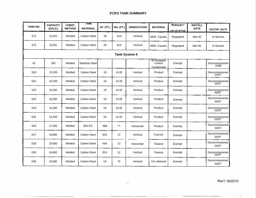
S71 10,201 Welded Carbon Steel 20 10.5 Vertical WDF; Caustic, Regulated Mar-92 In Service
S72 10,201 Welded Carbon Steel 20 10.5 Vertical WDF; Caustic, Regulated Mar-92 In Service
Tank System 4
Air Em~ssion 42 200 Welded Stainless Steel Control Exempt Decommissioned
Condensate 10109
S20 15,200 Welded Carbon Steel 19 14.33 Vertical Product Exempt Decommissioned 02/07
S21 15,200 Welded Carbon Steel 19 14.33 Vertical Product Exempt Decommissioned 02/07
S22 15,200 Welded Carbon Steel 19 14.33 Vertical Product Exempt Decommissioned 02/07 - _ _ _ _ _ - - P
S23 15,200 Welded Carbon Steel 19 14.33 Vertical Product Exempt Decommissioned 02/07
S24 15,200 Welded Carbon Steel 19 14.33 Vertical Product Exempt Decommissioned 02/07
S25 15,200 Welded Carbon Steel 19 14.33 Vertical Product Exempt Decommissioned 02/07
S26 17,000 Welded 304 S.S NIA 11 Horizontal Product Exempt Decommissioned 02/07
S27 16,800 Welded Carbon Steel 20.5 12 Vertical Fuel Oil Exempt Decommissioned 02/07 -_____-_________-- -
S28 23,650 Welded Carbon Steel NIA 12 Horizontal Toluene Exempt Decommissioned 02/07
S29 16,800 Welded Carbon Steel 20.5 12 Vertical Toluene Exempt Decommissioned 02/07
S30 10,000 Welded Carbon Steel 18 10 Vertical Cln. Material Exempt Decommissioned 02/07

PCPG TANK SUMMARY
TANK
S31
S32
533
S34
S35
S36
S37
S38
S39
S40
S41
S42
S43
S44
S45
CAPACITY (GALS.)
10,000
10,000
10,000
10,000
10,000
10,000
10,000
10,000
10,000
10,000
10,000
10,000
10,000
10,000
10,000
CONST. METHOD
Welded
Welded
Welded
Welded
Welded
Welded
Welded
Welded
Welded
Welded
Welded
Welded
Welded
Welded
Welded
TANK MATERIAL
Carbon Steel
Carbon Steel
Carbon Steel
Carbon Steel
Carbon Steel
Carbon Steel
Carbon Steel
Carbon Steel
Carbon Steel
Carbon Steel
Carbon Steel
Carbon Steel
Carbon Steel
Carbon Steel
Carbon Steel
HT. (FT.)
18
18
18
18
18
18
18
18
18
18
18
18
18
18
18
DIA. (FT.)
10
10
10
10
10
10
10
10
10
10
10
10
10
10
10
ORIENTATION
Vertical
Vertical
Vertical
Vertical
Vertical
Vertical
Vertical
Vertical
Vertical
Vertical
Vertical
Vertical
Vertical
Vertical
Vertical
MATERIAL
Cln. Material
Cln. Material
Cln. Material
Cln. Material
Cln. Material
Cln. Material
Cln. Material
Cln. Material
Cln. Material
Cln. Material
Cln. Material
Cln. Material
Cln. Material
Cln. Material
Cln. Material
RCRAlACT 45, STATUS
Exempt
Exempt
Exempt
Exempt
Exempt
Exempt - -
Exempt
Exempt
Exempt
Exempt
Exempt
Exempt
Exempt
Exempt
Exempt
INSTALL DATE
-
DECOM. DATE
Decommissioned 02/07
Decommissioned 02/07
Decommissioned 02/07
Decommissioned 02/07
Decommissioned 02/07
Decommissioned 02/07
Decommissioned 02/07
Decommissioned 02/07
Decommissioned 02/07
Decommissioned 02/07
Decommissioned 02/07
Decommissioned 02/07
Decommissioned 02/07
Decommissioned 02/07
Decommissioned 02/07
PCPG TANK SUMMARY n
TANK
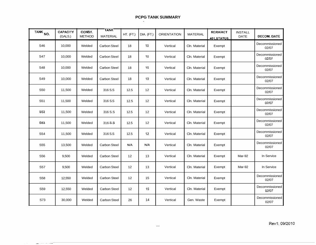
S46
S47
S48
S49
S50
S51
S52
553
S54
S55
S56
S57
S58
S59
S73
CAPACIN (GALS.)
10,000
10,000
10,000
10,000
11,500
11,500
11,500
11,500
11,500
13,500
9,500
9,500
12,550
12,550
30,000
CONST. METHOD
Welded
Welded
Welded
Welded
Welded
Welded
Welded
Welded
Welded
Welded
Welded
Welded
Welded
Welded
Welded
TANK MATERIAL
Carbon Steel
Carbon Steel
Carbon Steel
Carbon Steel
316 S.S
316 S.S
316 S.S
316 S.S
316 S.S
Carbon Steel
Carbon Steel
Carbon Steel
Carbon Steel
Carbon Steel
Carbon Steel
HT. (FT.)
18
18
18
18
12.5
12.5
12.5
12.5
12.5
N/A
12
12
12
12
26
DIA. (FT.)
10
10
10
10
12
12
12
12
12
N/A
13
13
15
15
14
ORIENTATION
Vertical
Vertical
Vertical
Vertical
Vertical
Vertical
Vertical
Vertical
Vertical
Vertical
Vertical
Vertical
Vertical
Vertical
Vertical
MATERIAL
Cln. Material
Cln. Material
Cln. Material
Cln. Material
Cln. Material
Cln. Material
Cln. Material
Cln. Material
Cln. Material
Cln. Material
Cln. Material
Cln. Material
Cln. Material
Cln. Material
Gen. Waste
RCRAlACT 451 STATUS
Exempt
Exempt
Exempt
Exempt
Exempt
Exempt
Exempt
Exempt
Exempt
Exempt
Exempt
Exempt
Exempt
Exempt
Exempt
INSTALL DATE
Mar-92
Mar-92
DECOM. DATE
Decommissioned 02/07
Decommissioned 02\07
Decommissioned 02/07
Decommissioned 02/07
Decommissioned 02/07
Decommissioned 02/07
Decommissioned 02/07
Decommissioned 02/07
Decommissioned 02/07
Decommissioned 02/07
In Service
In Service
Decommissioned 02/07
Decommissioned 02/07
Decommissioned 02/07
PCPG TANK SUMMARY
CAPACIN CONST. RCRAlACT 451 INSTALL DECOM. DATE
TANK HT. (FT.) DIA. (FT.) ORIENTATION MATERIAL
STATUS TANK
(GALS.) METHOD MATERIAL DATE
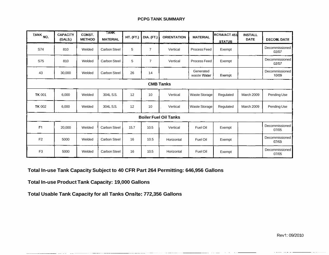
S74 81 0 Welded Carbon Steel 5 7 Vertical Process Feed Exempt Decommissioned 02\07
----- -
S75 81 0 Welded Carbon Steel 5 7 Vertical Process Feed Exempt Decommissioned 02/07
43 30,000 Welded Carbon Steel 26 14 Generated Exempt Decommissioned waste water 10109
CMB Tanks
TK 001 6,000 Welded 304L S.S. 12 10 Vertical Waste Storage Regulated March 2009 Pending Use
TK 002 6,000 Welded 304L S.S. 12 10 Vertical Waste Storage Regulated March 2009 Pending Use
Boiler Fuel Oil Tanks
F1 20,000 Welded Carbon Steel 15.7 10.5 Vertical Fuel Oil Exempt Decommissioned 07/05
F2 5000 Welded Carbon Steel 16 10.5 Horizontal Fuel Oil Exempt Decommissioned 07/05
F3 5000 Welded Carbon Steel 16 10.5 Horizontal Fuel Oil Decommissioned Exempt
07/05
Total In-use Tank Capacity Subject to 40 CFR Part 264 Permitting: 646,956 Gallons
Total In-use Product Tank Capacity: 19,000 Gallons
Total Usable Tank Capacity for all Tanks Onsite: 772,356 Gallons
Rev 1 : 09/20 1 0

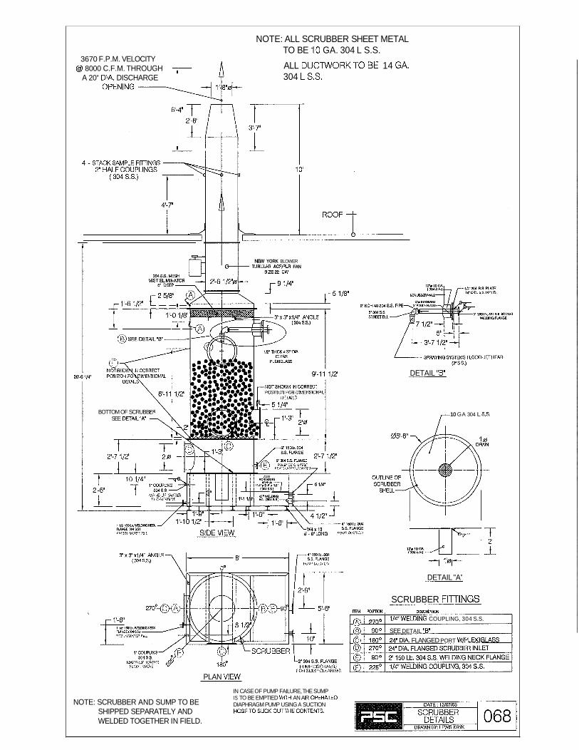
NOTE: ALL SCRUBBER SHEET METAL TO BE 10 GA. 304 L S.S.
3670 F.P.M. VELOCITY @ 8000 C.F.M. THROUGH ALL DUCTWORK TO BE 14 GA.
A 20" DIA. DISCHARGE 304 L S.S.
NEW YORK BLOWER NBUlAR ACFlPLR FAN
DETAIL "B"
BOTTOM OF SCRUBB 10 GA 304 L S.S. SEE DETAIL'A"
1 1'01-
DETAIL "A"
SCRUBBER FllTlNGS EM W ~ W , DESCRIPTKX(
@> 270" 114'WELDING COUPLING, 304 S.S.
@ 90' SEE DETAIL "B" (>; 180' 24' DIA. FLANGED PORT W/PLD(IGlASS
PLAN VIEW
IN CASE OF PUMP FAILURE, THE SUMP
NOTE: SCRUBBER AND SUMP TO BE IS TO BE EMPTIED WITH AN AIR OPERATED DIAPHRAGM PUMP USING A SUCTION
SHIPPED SEPARATELY AND HOSETO SUCK OUT THE C0NTEtfl.S.
WELDED TOGETHER IN FIELD.

4 1 '-4" OPEN TOP \ S Q . ~ ~
I
I
2"
OPEN BOTTOM .
SQ.
PERMANGANATE HOPPER
NOTE: ALL MATERIAL 16 GA. 304L S.S.
OPEN TOP OPEN END
SIDE VIEW OPEN END
PERMANGANATE FEED CHUTE

2" 304 S.S. COUPLING
2'-6''7 A

8000 C.F.M. @ 3800 F.P.M.
STACK SAMPLE AmNGS
4'-7
DE@ MICHIGAN DEPARTMENT OF ENVIRONMENTAL QUALITY - WASTE AND HAZARDOUS MATERIALS DIVISION P 0 Box 30241 Lansing, MI 48909-7741
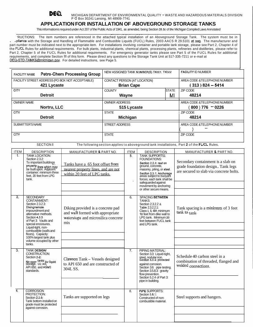
APPLICATION FOR INSTALLATION OF ABOVEGROUND STORAGE TANKS This information is required under Act 207 of the Public Acts of 1941, as amended, being Section 29.5~ of the Michigan Compiled Laws Annotated
'RUCTIONS: The item numbers are referenced in the attached typical installation of an Aboveground Storage Tank. The system must be in .tpliance with the Storage and Handling of Flammable and Combustible Liquids (FUCL) Rules, 2003 AACS R 29.5101 &see. The manufacturer and
part number must be indicated next to the appropriate item. For installations involving container and portable tank storage, please see Part 2, Chapter 4 of the FLICL Rules for additional requirements. For bulk plants, industrial plants, chemical plants, processing plants, refineries and distilleries, please refer to Part 2, Chapter 5 of the FUCL Rules for additional requirements. For emergency generator tanks please see Part 5 of the FUCL Rules for additional requirements, and complete Section Ill of this form. Please direct any questions to the Storage Tank Unit at 517-335-721 1 or e-mail at [email protected]. For detailed instructions, see Page 5.
I
I
OWNER NAME I OWNER ADDRESS I AREA CODE &TELEPHONE NUMBER
FACILITY NAME Petro-Chem Processing Group
FACILITY STREET ADDRESS (PO BOX NOT ACCEPTABLE)
421 Lycaste CITY
Detroit
NEW ASSIGNED TANK NUMBER@) TK001. TKO02
CONTACT PERSON (AT LOCATION)
Brian Cape
:
Nortru, LLC
I I I I
SECTION I The fol lowing sect ion applies t o aboveground tank installations, Part 2 o f the FLlCL Rules.
FACILITY ID NUMBER
AREA CODE &TELEPHONE NUMBER
( 313 ) 824 -5414 ZIP CODE
48214 COUNTY
Wayne
Detroit
SUBMITTER'S NAME
CITY
STATE
MI
CITY 1 STATE I ZIP CODE
515 Lycaste ( 800 ) 776 -- 0226
Michigan
STREET ADDRESS
STATE
ITEM 1.
2.
3.
4.
48214
AREA CODE &TELEPHONE NUMBER
( 1 -- ZIP CODE
DESCRIPTION TANK LOCATION: Section 2.3.2: To important buildings
lines which mky be built upon. Adjacent container: minimum three feet, 20 feet from LPG tank.
SECONDARY CONTAINMENT: Section 2.3.2.3: Dikinglremote impoundment and alternative methods. Section 4.3.3 of Part 3: Vaults and special enciosures. Liquid-tight, non- combustible (walls and floors). Capacity: 100% largest tank plus volume occupied by other tanks.
TANK DESIGN1 CONSTRUCTION: Section 2-2, No open for liquid storage. UL142, API 650, and ASME standards.
CORROSION PROTECTION: Section 2.2.6: Tank bottom installed on grade must be protected against corrosion.
MANUFACTURER & PART NO.
Tanks have a 65 foot offset from nearest property lines, and are not within 20 feet of LPG tanks.
Diking provided is a concrete pad and wall formed with appropriate waterstops and microsilica concrete mix
Clawson Tank - Vessels designed to API 650 and are constructed of 304L SS.
Tanks are supported on legs
ITEM 5.
,
6.
7.
8.
DESCRIPTION TANK SUPPORTS1 FOUNDATIONS: section 2.2.4: rest on ground, concrete, masonry, piling, or steel. Section 2,3,1: Anchorage areas subject to buoyant forces; each tank shall be safeguarded against movement by anchoring or other secure means.
SPACING BETWEEN TANKS: Section 2.3.2.2 & Table 2.3.2.2.1: Class I, II, lllA minimum 10 feet from dike wall to LPG tank. Minimum 20 feet between FUCL tank and LPG tank.
PIPING MATERIAL: Section 3.3: Liquid-tight, steel, nodular iron. section 3.5.4: Protected against corrosion. Section 3.6: pipe testing. Section 3.5.8.3: gravity flow prevention. Section 5.2.4 of Part 3: pipe in building.
PIPE SUPPORTS: Section 3.5.1: Constructed of non- combustible material.
MANUFACTURER & PART NO.
Secondary containment is a slab on grade foundation design.. Tank legs are secured to slab via concrete bolts.
Tank spacing is a minimum of 3 feet tank to tank-
Schedule 40 carbon steel in a combination of threaded, flanged and welded
Steel supports and hangers.
EQP3859 (REV 11/05) Page 1
(Continued on Page 2)
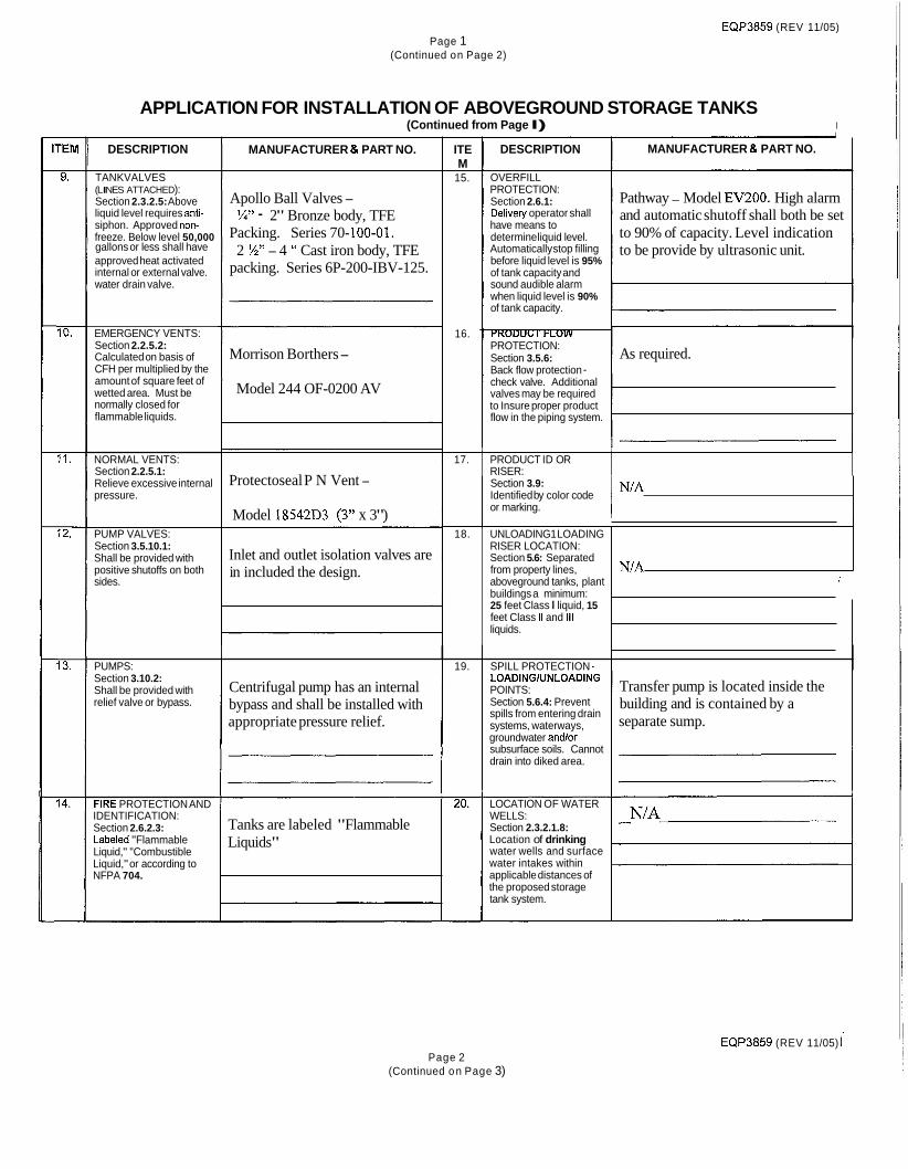
APPLICATION FOR INSTALLATION OF ABOVEGROUND STORAGE TANKS (Continued from Page I) I
i DESCRIPTION
1 TANKVALVES (LINES ATTACHED): Section 2.3.2.5: Above liquid level requires anti- siphon. Approved non- , freeze. Below level 50,000
I gallons or less shall have approved heat activated internal or external valve.
I water drain valve.
EMERGENCY VENTS: Section 2.2.5.2: Calculated on basis of CFH per multiplied by the amount of square feet of wetted area. Must be normally closed for flammable liquids.
NORMAL VENTS: Section 2.2.5.1: Relieve excessive internal pressure.
PUMP VALVES: Section 3.5.10.1: Shall be provided with positive shutoffs on both sides.
MANUFACTURER & PART NO.
Apollo Ball Valves - %" - 2" Bronze body, TFE
Packing. Series 70- 100-01. 2 34'' - 4 " Cast iron body, TFE
packing. Series 6P-200-IBV-125.
Morrison Borthers -
Model 244 OF-0200 AV
Protectoseal P N Vent -
Model 18542D3 (3" x 3")
Inlet and outlet isolation valves are in included the design.
ITE M -
15.
16.
DESCRIPTION
OVERFILL PROTECTION: Section 2.6.1: Delivety operator shall have means to determine liquid level. Automatically stop filling before liquid level is 95% of tank capacity and sound audible alarm when liquid level is 90% of tank capacity.
PROTECTION: Section 3.5.6: Back flow protection - check valve. Additional valves may be required to Insure proper product flow in the piping system.
MANUFACTURER & PART NO.
Pathway - Model EV200. High alarm and automatic shutoff shall both be set to 90% of capacity. Level indication to be provide by ultrasonic unit.
As required.
Section 3.9: Identified by color code or marking. I N'A
I I
17.
I PUMPS: I 1 19. I SPILL PROTECTION - I
PRODUCT ID OR RISER:
18.
Section 3.10.2: Shall be provided with relief valve or bypass.
FIRE PROTECTION AND IDENTIFICATION: Section 2.6.2.3: Labeled "Flammable Liquid," "Combustible Liquid," or according to NFPA 704.
UNLOADING1 LOADING RISER LOCATION: Section 5.6: Separated from property lines, aboveground tanks, plant buildings a minimum: 25 feet Class I liquid, 15 feet Class II and ill liquids.
Centrifugal pump has an internal bypass and shall be installed with appropriate pressure relief.
N/A I
LOADlNGlUNLOADlNG POINTS: Section 5.6.4: Prevent spills from entering drain systems, waterways, groundwater andlor subsurface soils. Cannot drain into diked area.
Transfer pump is located inside the building and is contained by a separate sump.
Tanks are labeled "Flammable Liquids"
LOCATION OF WATER WELLS: Section 2.3.2.1.8: Location of drinking water wells and surface water intakes within applicable distances of the proposed storage tank system.
EQP3859 (REV 11/05) i Page 2
(Continued o n Page 3)

AREABENEATH DISPENSER: Section 6.3.4.1: Designed to prevent leaks from entering groundwater, surface water or subsurface soils.
APPLICATION FOR INSTALLATION OF ABOVEGROUND STORAGE TANKS (Continued from Page 2)
SECTION II The following section applies to aboveground motor vehicle fueling and marina operations, Part 3 of the FLlCL Rules. The requirements in Chapters 1, 2, and 3 of Part 2 of the FUCL Rules must also be met. Inventory records shall be
EMERGENCY SHEARIFIRE VALVE:
I 'M , .
2.
3.
Section 6.3.9: Required on submerged pumping systems, rigidly anchored. Section 6.3.10: Suction systems require check valve or pressure regulating valve under the dispenser.
DISPENSING NOZZLE: Section 9.6.3: Automatic-closing with or without a latch open device. Section 6.6.6: Spiashguard required.
FIRE EXTINGUISHER: Section 9.2.5.2: Minimum of two listed 4A-20BC or one 4A-40BC within 75 feet of dispensers, fill pipes, and dispensing area.
MANUFACTURER & PART NO. kept for
DESCRIPTION TYPE OF SERVICE STATION: Attended qualified supervisor. Unattended self-service. Inside building. Marine service station.
LOCATION OF DISPENSER: Section 6.2.3: Minimum 10 feet from property lines, combustible building walls, and building openings. Within 100 feet of emergency shutoff switch. Section 9.4.5: In clear view of attendant.
DISPENSING DEVICE: Section 6.3.2: Must be listed and identified as to product it dispenses. Section 6.3.3: Equipped to aiiow control of flow. Section 6.3.4: Mounted on concrete island and protected from collision.
SIGNS: Section 9.2.5.4: Warning signs posted: "No Smoking," "Stop Motor," "Remain in attendance outside of vehicle and in view of the nozzle." Unlawful to dispense gasoline into unapproved containers. No filling of portable containers in or on a motor vehicle.
PHYSICAL PROTECTION: Section 4.3.7: Minimum 6-foot high chain link fence. Secure against unauthorized use and vehicular collision.
all Class I, Class 11, and Class IllA storage.
MANUFACTURER & PART NO.
EQP3859 (REV 11/05) Page 3
(Continued on Page 4)
ITEM 7.
8.
9.
DESCRIPTION DRAINAGE AND WASTE DISPOSAL: Section 9.2.6.3: Prevent spilled liquid from entering interior of service station. Section 9.2.6.4: Area should be protected to minimize spills from entering groundwater, surface water, and subsurface soils.
EMERGENCY BREAKAWAY DEVICE: Section 6.5: Installed on each hose that dispenses a liquid into motor vehicles. Designed to retain liquid on both sides of the breakaway point.
ANTI-SIPHON DEVICE: Section 4.2.4 & 4.3.6.5: Normally closed solenoid valve for elevated tanks.
APPLICATION FOR INSTALLATION OF ABOVEGROUND STORAGE TANKS (Continued from Page 3)
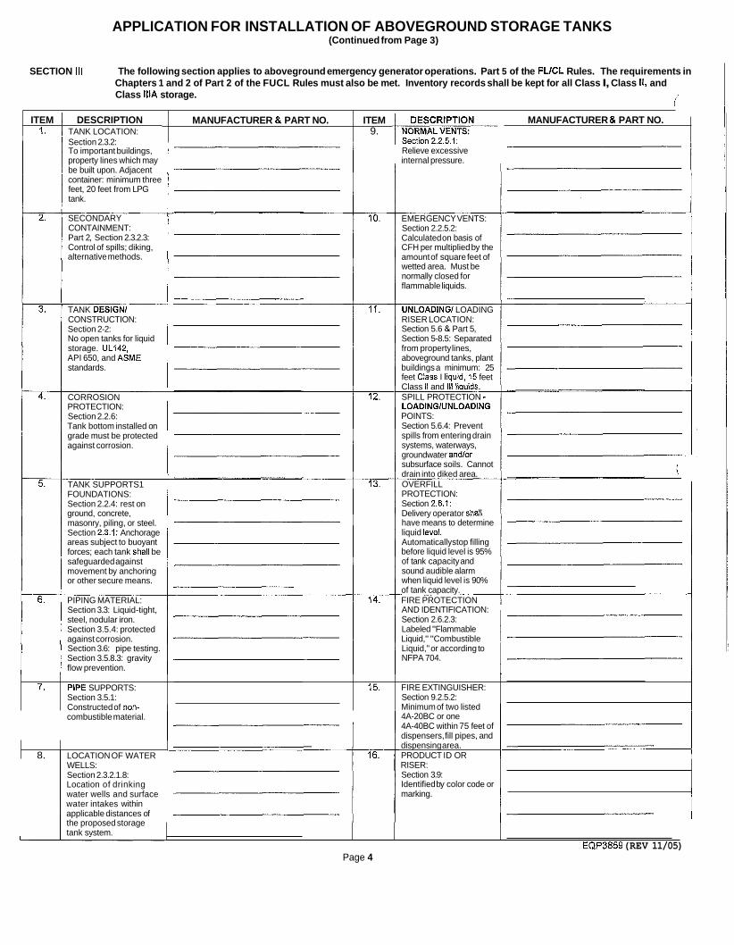
SECTION Ill The following section applies to aboveground emergency generator operations. Part 5 of the FLlCL Rules. The requirements in Chapters 1 and 2 of Part 2 of the FUCL Rules must also be met. Inventory records shall be kept for all Class I, Class 11, and Class lllA storage.
/' ITEM I DESCRIPTION
1. TANK LOCATION: MANUFACTURER & PART NO. MANUFACTURER & PART NO.
I 1 Section 2.3.2:
ITEM 9.
To important buildings, property lines which may be built upon. Adjacent container: minimum three feet, 20 feet from LPG tank.
Relieve excessive internal pressure.
I
2. SECONDARY CONTAINMENT:
EMERGENCY VENTS: Section 2.2.5.2: Calculated on basis of CFH per multiplied by the amount of square feet of wetted area. Must be normally closed for flammable liquids.
Part 2, Section 2.3.2.3: Control of spills; diking, alternative methods.
TANK DESIGN1 CONSTRUCTION:
UNLOADING1 LOADING RISER LOCATION:
I Section 2-2: No open tanks for liquid storage. UL142, ' API 650, and ASME standards.
Section 5.6 & Part 5, Section 5-8.5: Separated from property lines, aboveground tanks, plant buildings a minimum: 25 feet Class I liauid. 15 feet Class I\ and lli liq;ids. SPILL PROTECTION - CORROSION
PROTECTION: Section 2.2.6: Tank bottom installed on grade must be protected against corrosion.
LOADlNGlUNLOADlNG POINTS: Section 5.6.4: Prevent spills from entering drain systems, waterways, groundwater and/or subsurface soils. Cannot drain into diked area. OVERFILL TANK SUPPORTS1
FOUNDATIONS: Section 2.2.4: rest on ground, concrete, masonry, piling, or steel. Section 2.3.1: Anchorage areas subject to buoyant forces; each tank shall be safeguarded against movement by anchoring or other secure means.
PROTECTION: Section 2.6.1: Delivery operator shall have means to determine liquid level. Automatically stop filling before liquid level is 95% of tank capacity and sound audible alarm when liquid level is 90% of tank capacity. FIRE PROTECTION PIPING MATERIAL:
Section 3.3: Liquid-tight, steel, nodular iron. Section 3.5.4: protected against corrosion. Section 3.6: pipe testing. Section 3.5.8.3: gravity flow prevention.
AND IDENTIFICATION: Section 2.6.2.3: Labeled "Flammable Liquid," "Combustible Liquid," or according to NFPA 704.
combustible material.
7.
4A-20BC or one 4A-40BC within 75 feet of dispensers, fill pipes, and
8. 1 LOCATION OF WATER
PIPE SUPPORTS: Section 3.5.1: Constructed of non-
dispensing area. PRODUCT ID OR I
WELLS: Section 2.3.2.1.8: Location of drinking water wells and surface water intakes within applicable distances of the proposed storage tank svstem.
15.
RISER: Section 3.9: Identified by color code or
FIRE EXTINGUISHER: Section 9.2.5.2: Minimum of two listed
marking. I I EQP3859 (REV 11/05)
Page 4
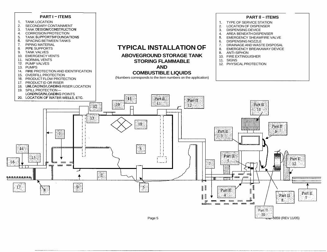
PART I - ITEMS 1. TANK LOCATION 2. SECONDARY CONTAINMENT 3. TANK DESlGNlCONSTRUCTlON 4. CORROSION PROTECTION 5. TANK SUPPORTSIFOUNDATIONS 6. SPACING BETWEEN TANKS 7. PIPING MATERIAL 8. PIPE SUPPORTS 9. TANK VALVES 10. EMERGENCY VENTS 11. NORMAL VENTS 12. PUMP VALVES 13. PUMPS 14. FIRE PROTECTION AND IDENTIFICATION 15. OVERFILL PROTECTION 16. PRODUCT FLOW PROTECTION
TYPICAL INSTALLATION OF ABOVEGROUND STORAGE TANK
STORING FLAMMABLE AND
COMBUSTIBLE LIQUIDS (Numbers corresponds to the item numbers on the application)
Page 5
PART II - ITEMS 1. TYPE OF SERVICE STATION 2. LOCATION OF DISPENSER 3. DISPENSING DEVICE 4. AREA BENEATH DISPENSER 5. EMERGENCY SHEAWFIRE VALVE 6. DISPENSING NOZZLE 7. DRAINAGE AND WASTE DISPOSAL 8. EMERGENCY BREAKAWAY DEVICE 9. ANTI-SIPHON 10. FIRE EXTINGUISHER 11. SIGNS 12. PHYSICAL PROTECTION
17. PRODUCT ID OR RISER 18. UNLOADINGILOADING RISER LOCATION 19. SPILL PROTECTION-
LOADINGIUNLOADING POINTS
859 (REV 11/05)

DEa MICHIGAN DEPARTMENT OF ENVIRONMENTAL QUALITY -WASTE AND HAZARDOUS MATERIALS DIVISION P 0 Box 30241 Lansing, MI 48909-7741
A plan review must be completed on any tank with a storage capacity greater than 1 , I 00 gallons storing flammable and combustible liquids. A request for plan review must include:
I ) Size of existing tank(s) and product stored, flash point. The material of construction, the dimension, and the capacity of each tank.
2) Type of impoundment (diking) provided. Provide dike calculations with the available capacity calculated.
3) A completed parts and materials list for each tank with vent manufacturer, model number and flow rate (gpm, SCFH) as appropriate.
4) A plot map showing the following information: a) Location of buildings, public roadways, railroad mainlines, public sidewalks,
and property lines. b) Storm sewers, sanitary sewers, manholes, and catch basins. c) Proposed location of the container(s) and loadinglunloading risers. d) Location of property lines. e) Location of existing tanks, above and underground, within 50 feet of the
installation. f) Location of fuel dispensers and canopy footings. g) The location of surface water and wetlands within 25 feet of the installation. I h) The location of single-family drinking wells, and community and non-
community public drinking water wells. 4) A separate piping diagram for each tank with pipe, vent and valve specification
identified on the diagram. Include manufacturer and model numbers where appropriate. i
5) Pipe systems must meet Chapter 3, NFPA 30, 2000 edition, requirements for gravity releases, emergency operation, and anti-siphon. Please show specific valves, vents and locations.
6) Tanks that do not have secondary containment shall not be installed in a delineated wellhead protection area. Tanks that do not have secondary containment shall not be installed in a source water protection area critical assessment zone, or 300 feet from a surface watershed delineated critical assessment zone.
7) A tank of more than 4,000 gallons shall not be installed within the critical assessment zone.
8) A plan review fee of $203 (checks made payable to the State of Michigan) per tank. Send the application to:
DEQ OFFICE OF FINANCIAL MANAGEMENT REVENUE CONTROL UNIT PO BOX 30657 LANSING, MI 48909
9) Section I shall be completed for bulk facilities. 1O)Sections I and II shall be completed for motor fueling facilities. 1l)Section Ill shall be completed for emergency generator facilities.
I
The facility cannot be operated without approval from the Waste and Hazardous Materials Division. If you have any additional questions concerning this matter, please contact the Storage Tank Unit at 517-335-721 1, or e-mail [email protected].
Page 6 EQP3859 (Rev 11/05) I