attachment 2 structural package evaluation - nrc.gov · title: structural evalation oshe d.c. cook...
TRANSCRIPT
ATTACHMENT 2STRUCTURAL PACKAGE EVALUATION
(1) ST-452, Structural Evaluation of the D.C. Cook Unit I SGLAClosures
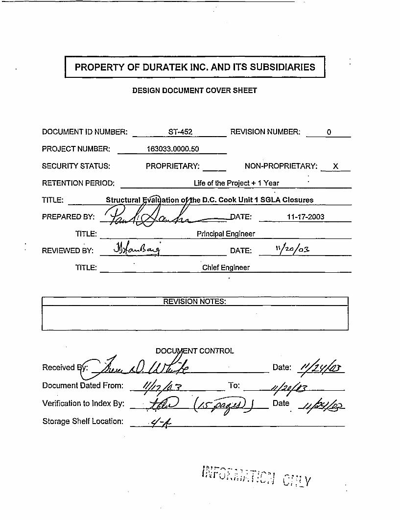
| PROPERTY OF DURATEK INC. AND ITS SUBSIDIARIES IDESIGN DOCUMENT COVER SHEET
DOCUMENT ID NUMBER: ST-452 REVISION NUMBER: 0
PROJECT NUMBER: 163033.0000.50
SECURITY STATUS: PROPRIETARY: NON-PROPRIETARY: X
RETENTION PERIOD: Life of the Project + 1 Year
TITLE: Structural evalation oShe D.C. Cook Unit I SGLA Closures
PREPARED BY: _---DATE: 11-17-2003
TITLE: Principal Engineer
REVIEWED BY: _ __ __ DATE: _ _ _ _ _ _ _ _
TITLE: Chief Engineer
REVISION NOTES:
Received
Document Dal
Verification to
Storage Shelf
DOCUENT CONTROLI, ,6.7Nted From: /7/ A / To: ____To
Index By: g) (5. a jLocation: . /
Date:
Date ,,AA,-7 4z-
'% ?s T- ee -% - ; #& -. ; i - i
PROPERTY OF DURATEK INC. AND ITS SUBSIDIARIES
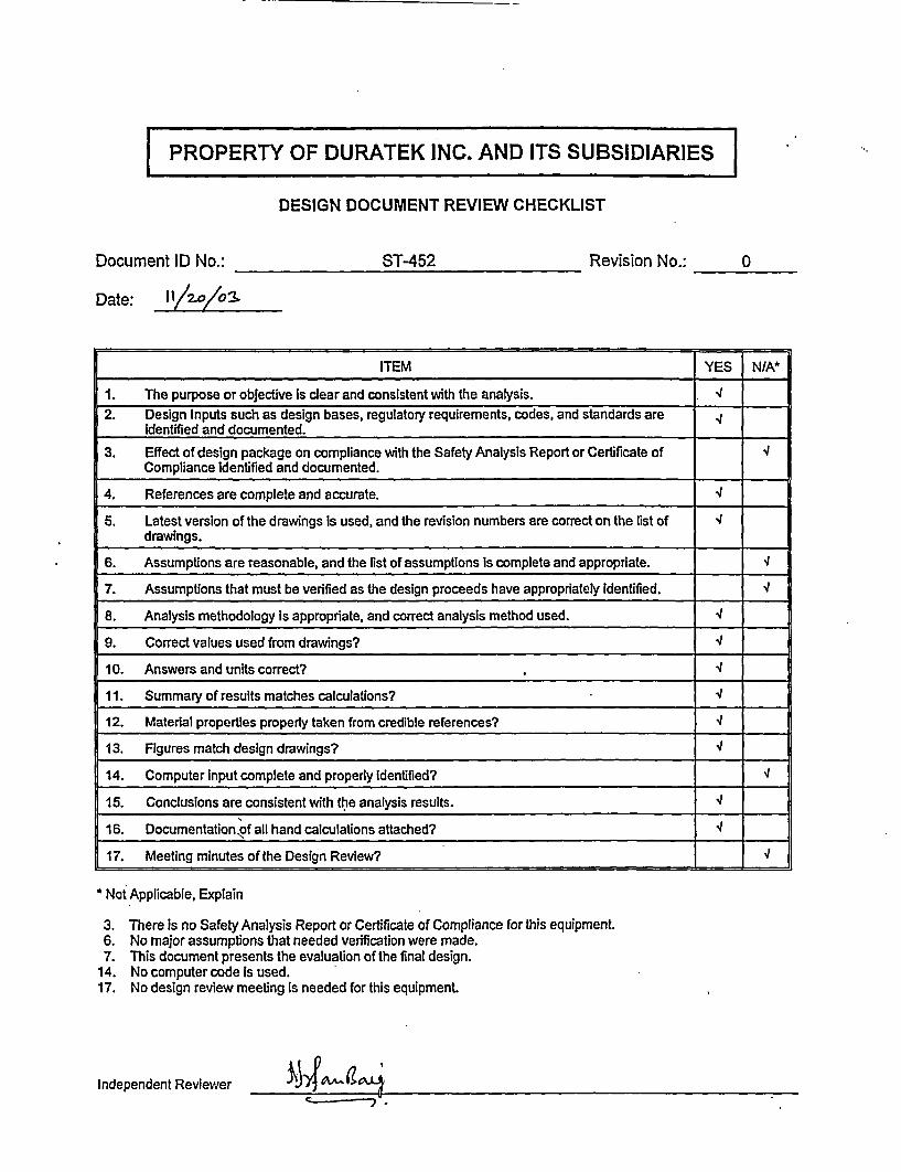
DESIGN DOCUMENT REVIEW CHECKLIST
Document ID No.: ST-452 Revision No.: 0
Date: IV/a3
ITEM YES N/A*
1. The purpose or objective Is clear and consistent with the analysis. l2. Design Inputs such as design bases, regulatory requirements, codes, and standards are
Identified and documented.
3. Effect of design package on compliance with the Safety Analysis Report or Certificate of 4Compliance identified and documented.
4. References are complete and accurate.
5. Latest version of the drawings Is used, and the revision numbers are correct on the list of 4drawings.
6. Assumptions are reasonable, and the list of assumptions Is complete and appropriate. v
7. Assumptions that must be verified as the design proceeds have appropriately Identified. 4
8. Analysis methodology is appropriate, and correct analysis method used. 4
9. Correct values used from drawings? 4J
10. Answers and units correct? .
11. Summary of results matches calculations?
12. Material properties properly taken from credible references? 4
13. Figures match design drawings? 4
14. Computer Input complete and properly identified? v
15. Conclusions are consistent with the analysis results. 4
16. Documentationxof all hand calculations attached? 4
17. Meeting minutes of the Design Review?
* Not Applicable, Explain
3. There is no Safety Analysis Report or Certificate of Compliance for this equipment.6. No major assumptions that needed verification were made.7. This document presents the evaluation of the final design.
14. No computer code is used.17. No design review meeting is needed for this equipment.
Independent Reviewer

| PROPERTY OF DURATEK INC. AND ITS SUBSIDIARIES |
DESIGN DOCUMENT REVIEW METHOD CHECKLIST
Document ID No.: ST-452 Revision No.: 0
Date: I k/ 0/a 3
n7EM
1. Altemate or simplified computational method.
2. Comparison of results to other calculations of a similar nature.
3. Numerical repetition of the calculations. -4
4. Comparison of calculations with experimental results.
5. Other (specify)
6. Comments:
Independent Reviewer
Title Structural Evaluation of the D.C. Cook Unit 1 SGLA Closures
Calc. No. ST-452 Rev. 0 Sheet I of 12
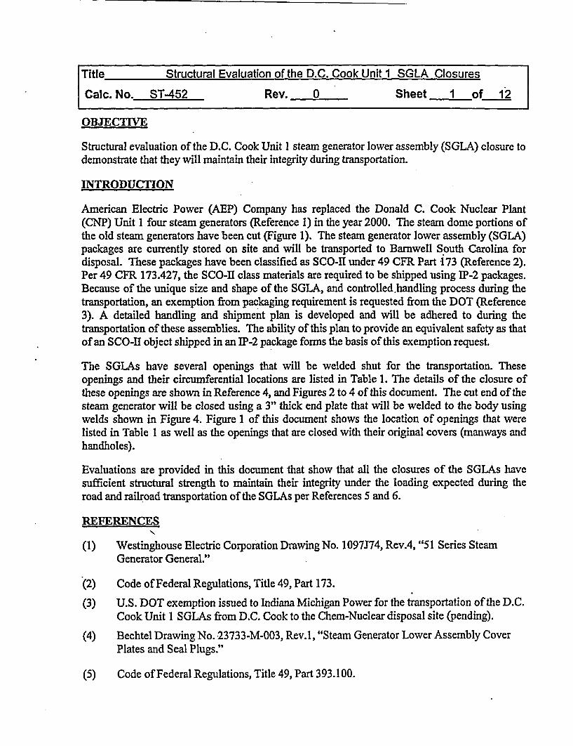
OBJECTIVE
Structural evaluation of the D.C. Cook Unit I steam generator lower assembly (SGLA) closure todemonstrate that they will maintain their integrity during transportation.
INTRODUCTION
American Electric Power (AEP) Company has replaced the Donald C. Cook Nuclear Plant(CNP) Unit 1 four steam generators (Reference 1) in the year 2000. The steam dome portions ofthe old steam generators have been cut (Figure 1). The steam generator lower assembly (SGLA)packages are currently stored on site and will be transported to Barnwell South Carolina fordisposal. These packages have been classified as SCO-il under 49 CFR Part 173 (Reference 2).Per 49 CFR 173.427, the SCO-II class materials are required to be shipped using IP-2 packages.Because of the unique size and shape of the SGLA, and controlled.handling process during thetransportation, an exemption from packaging requirement is requested from the DOT (Reference3). A detailed handling and shipment plan is developed and will be adhered to during thetransportation of these assemblies. The ability of this plan to provide an equivalent safety as thatof an SCO-Il object shipped in an IP-2 package forms the basis of this exemption request.
The SGLAs have several openings that will be welded shut for the transportation. Theseopenings and their circumferential locations are listed in Table 1. The details of the closure ofthese openings are shown in Reference 4, and Figures 2 to 4 of this document. The cut end of thesteam generator will be closed using a 3" thick end plate that will be welded to the body usingwelds shown in Figure 4. Figure 1 of this document shows the location of openings that werelisted in Table 1 as well as the openings that are closed with their original covers (manways andhandholes).
Evaluations are provided in this document that show that all the closures of the SGLAs havesufficient structural strength to maintain their integrity under the loading expected during theroad and railroad transportation of the SGLAs per References 5 and 6.
REFERENCES
(1) Westinghouse Electric Corporation Drawing No. 1097J74, Rev.4, "51 Series SteamGenerator General."
(2) Code of Federal Regulations, Title 49, Part 173.
(3) U.S. DOT exemption issued to Indiana Michigan Power for the transportation of the D.C.Cook Unit 1 SGLAs from D.C. Cook to the Chem-Nuclear disposal site (pending).
(4) Bechtel Drawing No. 23733-M-003, Rev.1, "Steam Generator Lower Assembly CoverPlates and Seal Plugs."
(5) Code of Federal Regulations, Title 49, Part 393.100.
Title Structural Evaluation of the D.C. Cook Unit 1 SGLA Closures
Calc. No. ST-452 Rev. 0 Sheet 2 of 12
(6) AAR Manual, Rev.9, Section No.1, General Rules, 1993.
(7) AISC, Steel Construction Manual, Ninth Edition.
(8) Duratek drawing C-068-163033-001, Rev 0, "D.C. Cook Unit 1 SGLA GeneralArrangement."
MATERIAL PROPERTIES
Shells
Specification: ASME SA-533 Type A, Class 1
Minimum Yield Strength, Sy = 50,000 psi
Minimum Ultimate Strength, Su, = 80,000 psi
Caps and Plugs
Specification: ASTM A-36
Minimum Yield Strength, Sy = 36,000 psi
Minimum Ultimate Strength, S. = 58,000 psi
Welds
Rod Specification: E-70xx Electrodes
Minimum Ultimate Strength, S. = 70,000 psi
ALLOWABLE STRESSES
Stresses in the caps and plugs and the welds are conservatively based on the AISC (Reference 7)allowable value's for A-36 material.
Caps and Plugs
Allowable bending stress = 0.66 Sy = 24,000 psi
Allowable shear stress = 0.4 Sy = 14,400 psi
Welds
Allowable shear stress in fillet welds = 0.3 S. = 21,000 psi
Title Structural Evaluation of the D.C. Cook Unit 1 SGLA Closures
CaIc. No. ST-452 Rev. 0 Sheet 3 of 12
EVALUATION OF THE CLOSURES
The closures of the SGLAs are evaluated for the largest acceleration that they may experienceduring the road and rail transportation per References 5 and 6. Of the two modes oftransportation, the largest acceleration on the SGLAs occurs during the rail transportation.According to the requirements of the AAR Manual (Reference 6) the largest accelerationexperienced by the SGLAs is 3g in the longitudinal direction. Conservatively, 3g acceleration isassumed to occur in all directions and the closures are analyzed for this loading.
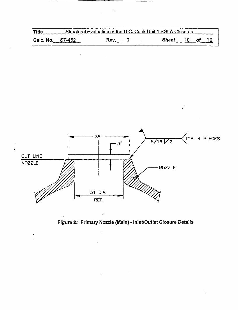
Primary (Main) Inlet & Outlet Nozzle Closures (Reference 4, Detail 2)
The primary (main) inlet and outlet nozzle closures are shown in Figure 2. The closure plates are3" thick and have a diameter of 35 inch. The weight of the closure plate is:
W = 7r/4x35 2x3x0.283 = 817 lbs
The maximum bending moment in the closure plate is:
Mc = qxa2x(3+v)/l 6
Where,
q = uniformly distributed load intensity for 3g acceleration
q=3x817/(7Ir4x352 ) = 2.55 psi
a = radius of the plate = 35/2 = 17.5 in
Therefore,
Mc= 2.55x1 7.52 x3.3/16 = 161 in-lblin
The maximum bending stress in the plate is:NI
ab = 6xM/t?
Where,
t = plate thickness = 3"
Therefore,
Gb = 6x1 61/32= 107 psi << 24,000 psi O.K.
The closure plates are held by four 5/16" fillet welds 2" long (Reference 4). The remainder of thecircumference of the plate is seal welded. Taking no credit for the seal weld, the shear stress inthe fillet weld is:
Title Structural Evaluation of the D.C. Cook Unit I SGLA Closures
Calc. No. ST-452 Rev. 0 Sheet 4 of 12
T, = 3x817/(4x2x0.707x5/16) = 1,387 psi
Considering the inertia load to act at the C.G. of the plate, the bending moment on the weldgroup is:
M = 3x817x1.5 = 3,677 in-lb
Conservatively consider only two of the four welds to calculate the section modulus of the weldgroup. Also assume these welds to be located at location diametrically opposite each other. Thesection modulus for the weld group consisting of two 5/16" fillet welds, 2" long and 35" apartabout the axis parallel to the weld length is:
S = 2x35x0.707x0.3125 = 15.47 in3
Therefore, the shear stress in the weld group due to bending moment,
fib =3,677/15.47 = 238 psi
Total shear stress, X = 1,387 + 238= 1,625 psi << 21,000 psi O.K.
Manway Closures
The primary manways are closed with the original covers. These manways have a 16-inch insidediameter; the covers are 4.60 inches thick and are 26.75 inches in diameter (Per the Figure 1-1outline drawing listed in Reference 8). Then, the manway cover weight (Wm) is:
Wm = (7ri4)x26.752X4.60X (1/12) 3x490 = 733 lbs, say 1,000 lbs to account for the insert
Under 3g load the manway cover will be loaded by a uniform pressure of,
q= (3xl,000)/[(r/4)x16 2] = 14.9 psi
The primary side of these steam generators is designed for 2,485-psig internal pressure and ishydro tested to-3,106-psig (Per the Figure 1-1 outline drawing listed in Reference 8). Underthese pressures the manways remain closed and sealed. Therefore, under the small 14.9 psitransport loading the manways will remain intact.
Handhole Closures
The secondary handholes are closed with the original covers. These covers are fitted over 6"diameter nozzles, each cover is 11.62 inches in diameter and is 1.60 inches thick (Per the Figure1-1 outline drawing listed in Reference 8).
Then, the handhole cover weight (Wh) is:
Wh = (it/4)xl 1.622xl.60x (1/12) 3x490 = 48 lbs, say 80 lbs
Title Structural Evaluation of the D.C. Cook Unit I SGLA Closures
Calc. No. ST-452 Rev. 0 Sheet 5 of 12
Under 3g load they will be loaded by a uniform pressure of,
q = 3x80/(n/4x62) = 8.5 psi
This pressure is even smaller than that of the manways shown above and therefore by the samejustification the handholes will remain intact during transportation.
Bottom Blow-Down, Shell Drain and Wide Range Water Level Tap Nozzle Closures(Reference 4. Detail 31
The bottom blow-down, shell drain and wide range water level tap nozzle closures are closedusing plugs, as shown in Reference 4. The schedule of the plugs used for the closure of theseopenings is also given in Figure 3 of this document.
Per Reference 4 drawing, all plugs are welded in place using continuous seal weld all around theplug. For the evaluation purposes, this document considers a 1/8" continuous fillet weld allaround. Conservatively using the largest plug diameter (1.6875') and a plug length of 3 ¼4" tocalculate the maximum plug weight. The maximum plug weight (W) is:
W = (7r14) x 1.68752 x 3.25 x 0.284 = 2.1 lbs say 5 lbs
Calculating the weld shear stress using the smallest plug diameter, the weld shear stress (r) is:
r = 3x5/(icxO.57375x0.707xO.l25) = 94.2 psi <c 21,000 psi O.K.
End Closure (Reference 4. Detail 1)
The end closure of the SGLA is made from a 3" thick by 167.75" diameter cover plate. Theclosure assembly is shown in Figure 4. The weight of the cover plate is:
W = (m4)x167.752x3x0.284 = 18,830 Ibs
The maximum bending moment in the closure plate is:
Mc = qxa2x(3+v)/l 6
Where,
q = uniformly distributed load intensity for 3g acceleration
q = (3xI 8,830)/[(r/4)xl 67.752] = 2.56 psi
a = radius of the plate = 167.75/2 = 83.875 in
Therefore,
M, = 2.56x83.875 2x3.3/16 = 3,715 in-lb/in
Title Structural Evaluation of the D.C. Cook Unit I SGLA Closures
Calc. No. ST-452 Rev. 0 Sheet 6 of 12
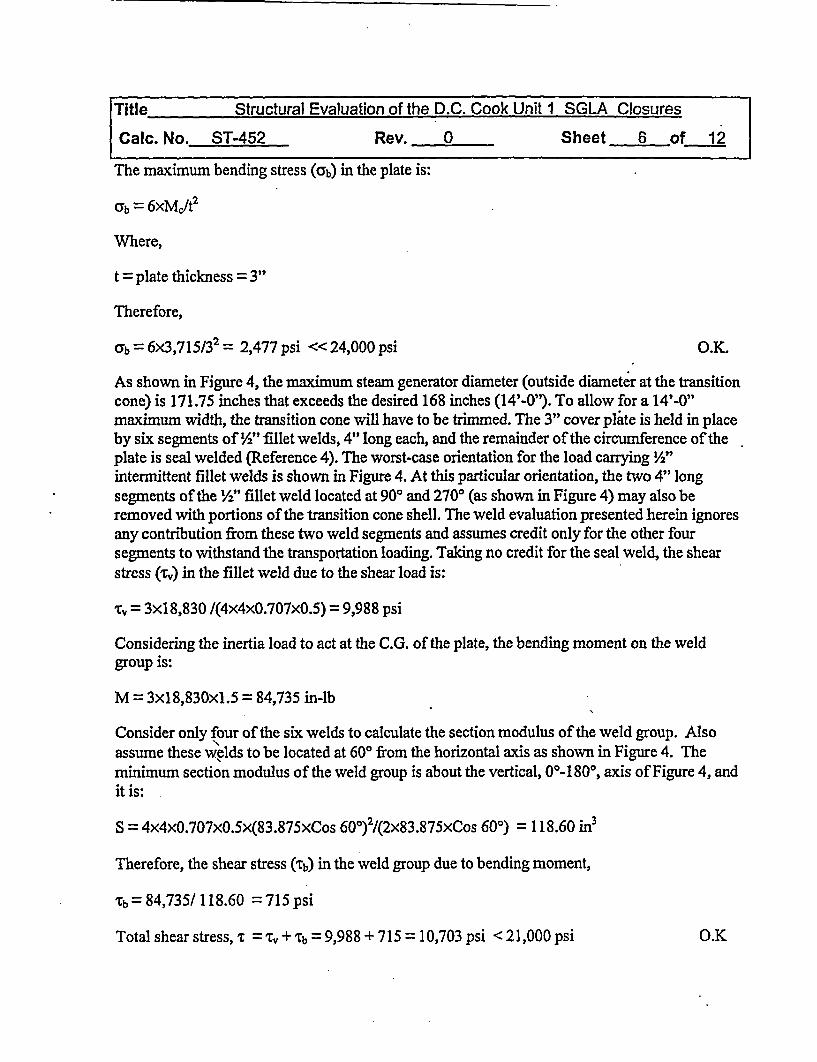
The maximum bending stress (ab) in the plate is:
ab = 6xMct 2
Were,
t = plate thickness = 3"
Therefore,
ab = 6x3,715/32 = 2,477 psi <24,000 psi O.K
As shown in Figure 4, the maximum steam generator diameter (outside diameter at the transitioncone) is 171.75 inches that exceeds the desired 168 inches (14'-O'). To allow for a 14'-0"maximum width, the transition cone will have to be trimmed. The 3" cover plate is held in placeby six segments of l2' fillet welds, 4" long each, and the remainder of the circumference of theplate is seal welded (Reference 4). The worst-case orientation for the load carrying V2"intermittent fillet welds is shown in Figure 4. At this particular orientation, the two 4" longsegments of the 1/2W fillet weld located at 900 and 270° (as shown in Figure 4) may also beremoved with portions of the transition cone shell. The weld evaluation presented herein ignoresany contribution from these two weld segments and assumes credit only for the other foursegments to withstand the transportation loading. Taking no credit for the seal weld, the shearstress (Tv) in the fillet weld due to the shear load is:
r= 3x1 8,830 /(4x4x0.707x0.5) 9,988 psi
Considering the inertia load to act at the C.G. of the plate, the bending moment on the weldgroup is:
M = 3x18,830xl.5 = 84,735 in-lb
Consider only four of the six welds to calculate the section modulus of the weld group. Alsoassume these welds to be located at 600 from the horizontal axis as shown in Figure 4. Theminimum section modulus of the weld group is about the vertical, 0°-180°, axis of Figure 4, andit is:
S = 4x4x0.707x0.5x(83.875xCos 60') 2/(2x83.875xCos 600) = 118.60 in3
Therefore, the shear stress (lb) in the weld group due to bending moment,
Xb = 84,735/ 118.60 = 715 psi
Total shear stress, l = Tr + ¶b = 9,988 + 715 = 10,703 psi <21,000 psi O.K
....
Title Structur
Calc. No. ST-452
ral Evaluation of the D.C. Cook Unit I
Rev. 0
SGLA Closures
Sheet 7 of 12
CONCLUSIONS
It has been shown in this report that all the closures of the SGLA have adequate strength to reactto the load normally expected during its transportation by road or rail (per References 5 and 6).The stress allowables based on the AISC criteria are satisfied by all the components of theclosure assembly with an acceptable margin of safety. The SGLAs will, therefore, remaincompletely sealed and behave like a unitized body during transportation. An exemption frompackaging the SGLAs during transportation has, therefore, been requested from the DOT.
Title Structural Evaluation of the D.C. Cook Unit I SGLA Closures
Calc. No. ST-452 Rev. 0 Sheet 8 of 12
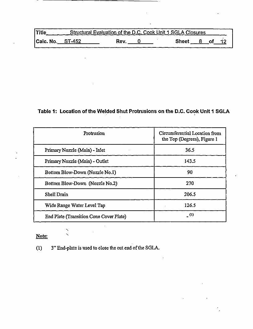
Table 1: Location of the Welded Shut Protrusions on the D.C. Cook Unit I SGLA
Protrusion Circumferential Location fromthe Top (Degrees), Figure 1
Primary Nozzle (Main) - Inlet 36.5
Primary Nozzle (Main) - Outlet 143.5
Bottom Blow-Down (Nozzle No.1) 90
Bottom Blow-Down (Nozzle No.2) 270
Shell Drain 206.5
Wide Range Water Level Tap 126.5
End Plate (Transition Cone Cover Plate) - (1)
N
Note:
(1) 3" End-plate is used to close the cut end of the SGLA.

Title Structural Evaluation of the D.C. Cook Unit I SGLA Closures
Calc. No. ST-452 Rev. 0 Sheet 9 of 12
-PRIMARYNOZZLE (MAIN, 2X)
(PRIMARY, 2X)
WIDE RANGE WATERLEVEL TAP
-SUPPORT PAD (TYP. 4 PLCS)
PRIMARY NOZZLE (MAIN)
- 900
- BOTTOM BLOW-DOWNEB0TTOM
WIDE RANGE WATER LEVEL TAP
SHELLK DRAIN-
END VIEWTRUE ORIENTATION
Figure 1: DC Cook Unit 1 SGLA Protrusion Location
Title Structural Evaluation of the D.C. Cook Unit 1 SGLA Closures
Caic. No. ST-452 Rev. 0 Sheet 10 of 12
4 PLACES
CUT LINENOZZLE
Figure 2: Primary Nozzle (Main) - Inlet/Outlet Closure Details

Title Structural Evaluation of the D.C. Cook Unit 1 SGLA Closures
Calc. No. ST-452 Rev. 0 Sheet 11 of 12
PlugDetil L
.~~~~~
PLUG SCHEDULE
"A" Plug Dimension
Closure Description Per Nominal Maximum Minimum Maximum WeldClosur Desc S.G. I.D. Plug Dia. Plug Dia. Plug Length
Bottom Blow-Down Nozzle 2 1 23/32" 1.6875" 1.6675" 3 ¼" 1/8"
Shell Drain 1 1I 0.8125" 0.7925" 3 14" 1/8"
Wide Range Water Level Tap 1 3 4" 0.59375" 0.57375 3 ¼4" 1/8"
Figure 3: Small Nozzle Closure Using Plugs

Title Structural Evaluation of the D.C. Cook Unit 1 SGLA Closures
Calc. No. ST-452 Rev. 0 Sheet 12 of 12
14'-O WIDE WINDOW
0 0
900 2700
60,(REV.)
N /180° AU CNIERLINE | / TYP. 6 PLA CES
'N I
I
COVER PLATE 167.75' DAI. X 3' THK
STEAM GENERATOR O.D. - 171.75 -
Figure 4: SGLA End Closure Details

ATTACHMENT 3SGLA GENERAL ARRANGEMENT
ANDCLOSURE DRAWINGS
(1) Westinghouse Drawing, (1097J74) "General Arrangement"
(2) "Figure 1-1 Outline from Westinghouse Electric CoSteam Generator Manual for D.C. Cook" - 2 Pages
(3) Bechtel Drawing, 23733-M-003 Rev I - "Steam GeneratorLower Assembly Cover Plates and Seal Plugs"

q - i
THIS PAGE IS ANOVERSIZED
DRAWING ORFIGURE,
THAT CAN BE VIEWED ATTHE RECORD TITLED:
DWG. NO . : 1 097J74"GENERAL ARRANGEMENT"
WITHIN THIS PACKAGE..OR-BY
SEARCHING USING,
DWG. NO. 1097J74
D-O1
THIS PAGE IS ANOVERSIZED
DRAWING ORFIGURE,
THAT CAN BE VIEWED ATTHE RECORD TITLED:
DWG. NO. 23733-;M-003, REV. 1
"STEAM GENERATOR LOWERASSEMBLY COVER PLATES AND
SEAL PLUGS"WTHIN THIS PACKAGE..
OR BYSEARCHING USINGDWG. NO. 23733-M- 003
D-02
ATTACHMENT 4TRANSPORTATION SYSTEMGENERAL ARRANGEMENTS
DRAWINGS
(1) Duratek Drawing, C-068-163033-001 Rev 0, "D. C. CookUnit I SGLA General Arrangement"
(2) Duratek Drawing, C-068-163033-010 Rev 0, "D.C. CookUnit I SGLA Road Transportation General Arrangement"
(3) Duratek Drawing, C-068-163033-020 Rev 0, "D.C. Cook Unit ISGLA Rail Transportation General Arrangement"