attachment 1 survey disk diagrams - u.s. … a...attachment 1 survey disk diagrams to general...
TRANSCRIPT

ATTACHMENT 1SURVEY DISK DIAGRAMS
TOGENERAL GUIDANCE AND SPECIFICATIONS FOR
AERONAUTICAL SURVEYS VOLUME A
FEDERAL AVIATION ADMINISTRATIONAIRPORT SURVEYS

Page 2
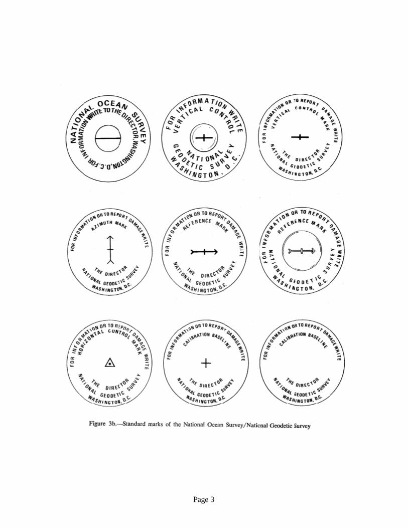
Survey Disk Diagrams
Page 3
Page 4
FOR
INFO
RMAT
ION OR TO REPORT DAMAGE W
RITE
WASHINGTON, D.C.NATIONAL OCEAN SERVIC
E
FOR
INFO
RMAT
ION OR TO REPORT DAMAG
E WR
ITE
WASHINGTON, D.C.
NATIONAL OCEAN SERVICE
T IDAL BENCH MARK
FOR
INFO
RMAT
ION OR TO REPORT DAMAGE W
RITE
WASH INGTON, D.C.
NAT IONA L GEODETIC SURVEY
GEODETIC CONTROL MARK
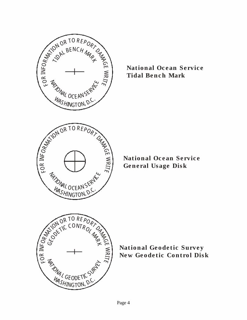
National Ocean ServiceTidal Bench Mark
National Ocean Service General Usage Disk
National Geodetic SurveyNew Geodetic Control Disk
ATTACHMENT 2SELECTION GUIDELINES FOR AIRPORT GEODETIC CONTROL SURVEYS
TOGENERAL GUIDANCE AND SPECIFICATIONS FOR
AERONAUTICAL SURVEYS VOLUME A
FEDERAL AVIATION ADMINISTRATIONAIRPORT SURVEYS

1
ATTACHMENT 2
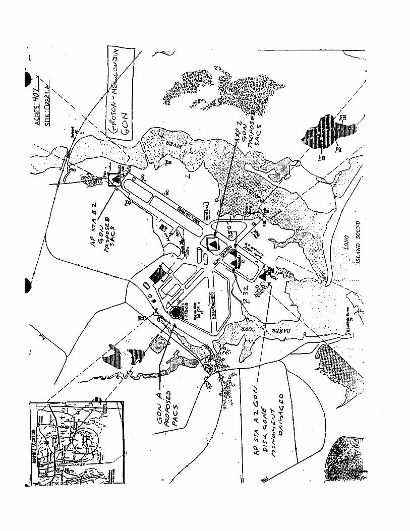
SELECTION GUIDELINES FOR AIRPORT GEODETIC CONTROL SURVEYS Three permanent survey marks shall be established on, or within one km of, the airport. One of these marks shall be designated the Primary Airport Control Station (PACS). Horizontal and vertical datum ties shall be made directly between the PACS and the National Spatial Reference System (NSRS). The other two marks shall be designated Secondary Airport Control Stations (SACS). Horizontal and vertical connections shall be made directly between the SACS and the PACS. Existing stations may be used as the PACS and SACS if they meet the accuracy, siting, construction, and other criteria identified in this attachment and the accuracy’s in FAA No. 405, Standards for Appendix 5. Proper monument site selection for PACS and SACS is a primary goal for these surveys and must be carefully considered. Factors to consider are monument stability, intervisibility requirements, visibility from the monuments to airport features such as runways, navigation aids, and airport obstructions off the end of runways, any previous high accuracy connection to the National Spatial Reference System (NSRS), accessibility, and survivability of the monuments. The monuments must be accessible to survey crews, and allow for unattended, secure setup of GPS equipment for long periods without hindering airport operations. PACS and SACS must allow for setup of both conventional (optical) and satellite surveying equipment. If possible, SACS should be sited on high ground near the approach end of the primary runways so they can be better utilized for obstruction surveys. Monuments must be established in areas clear of future construction, and should be slightly recessed to protect them from snow removal and mowing equipment. CONTROL STATION SELECTION PRIORITIES PACS –
1) An existing mark may be used as a PACS if the mark meets the stability codes of A or B in that order of preference (see mark stability standards below).
2) An existing concrete mark with stability code C (and 4+ feet deep, belled bottom) may be used for a PACS if the disk: (1) already exists, (2) is poured in place concrete, (3) is a triangulation station, reference mark, azimuth mark, or bench mark stamped "U.S. Coast and Geodetic Survey", or any mark stamped "National Geodetic Survey", (4) is set below the frost line, (5) is set in nonexpansive soils, (6) shows no evidence of movement and (7) meets all siting, construction, and intervisibility requirements.
Note, an existing HARN station ("A" or "B" order station) does not necessarily qualify to be a
PACS, it must still meet PACS stability and siting requirements. SACS –
1) An existing mark may be used as a SACS if the mark meets the stability codes of A, B or C in that order of preference.
2
Note, other USC&GS, NGS, or NOS marks should be used as SACS if they meet all siting,
construction, and intervisibility requirements. CONTROL STATION SITING The following are a list of considerations for every monument (new or old, control station or local network station) in the project. The intent is to ensure that stations will be stable and usable years after the survey is completed. Each of the considerations are important, and so, they are not prioritized. * Adequate GPS satellite visibility (unrestricted at 15 degrees above the horizon). Minor obstructions may be acceptable, but must be depicted on the Visibility Obstruction Diagram. * Accessible by vehicle (two-wheel drive preferred). * Stability, bedrock being most preferred. See below. * Permanency. * Ease of recovery. * Minimal multi-path. * Appropriate geographic location and spacing. * Location allows efficient use by surveying community. * Accessible by public. Public property should be utilized where feasible. * No known potential conflict with future development. * Aerial-photo identifiable. PACS AND SACS PROXIMITY TO AIRPORT FEATURES PACS shall be established in a secure area on airport property. A GPS suitable site should be selected where surveying equipment may be left unattended at the mark with a minimum probability of disturbance. SACS should be established on airport property if practical. However, if the siting requirements, such as, intervisibility and spacing as described below, cannot be met, one SACS may be set off the airport but no further than 1 km from the nearest airport boundary.

3
If establishing the PACS and SACS requires new monumentation, the new monuments should be set no closer than 60 meters from a runway edge, or 60 meters from the imaginary runway extension. If an existing control station is used, this station should be at least 15 meters from a runway edge. In all cases, PACS and/or SACS should be at least 400 meters apart. PACS and SACS should be located so that a surveying tripod can be situated over the mark. In addition, if the mark could be in peril from snow removal, mowing, and other operations, it should be slightly recessed. PACS and SACS should be strategically located so as to provide maximum use for subsequent surveys yet situated where the chances of future disturbance will be minimal. An elevated site with runway end visibility is desirable. PACS and SACS should also be located where future station occupation will cause no interference to or from aircraft, including from prop and jet blast. The sight path between stations over paved areas should be minimized. PACS and/or SACS must not be within 305 meters (1000 ft) of the critical side of an:
Instrument Landing System (ILS) Glideslope Antenna, Instrument Landing System (ILS) Localizer, Microwave Landing System Elevation Station, Microwave Landing System Azimuth Station.
PACS AND SACS INTERVISIBILITY Intervisibility choices for PACS and SACS are: FIRST CHOICE The PACS and both SACS are all intervisible with each other. SECOND CHOICE The PACS is intervisible with both SACS but the SACS are not intervisible with each other. THIRD CHOICE The PACS is intervisible with one SACS and both SACS are intervisible with each other. STABILITY Stability codes A, B, and C are defined in the Blue Book, Volume 1, Annex I, with examples given below. Only codes A and B are recommended, however concrete posts may be selected with code C

4
stability if the mark is deemed stable from review of soil conditions and average frost depth. Stability code A = expected to hold an elevation. Examples: rock outcrops; rock ledges; bedrock; massive structures with deep foundations; large structures with foundations on bedrock; or sleeved deep settings (10 feet or more) with galvanized steel pipe, galvanized steel, stainless steel, or aluminum rods. Stability code B = probably hold an elevation. Examples: unsleeved deep settings; massive retaining walls; abutments and piers of large bridges or tunnels; unspecified rods or pipe in a sleeve less than 10 feet; or sleeved copper-clad steel rods. Stability code C = may hold an elevation but subject to ground movement. Examples: Metal rods with base plates less than 10 feet deep; concrete posts (3 feet or more deep); large boulders; retaining walls for culverts or small bridges; footings or foundation walls of small to medium-size structures; or foundations such as landings, platforms, or steps. MINIMUM ACCURACY REQUIREMENTS FOR PACS/SACS The required accuracy standards for PACS and SACS are listed below and are contained in FAA Number 405, “Standards for Aeronautical Surveys and Related Products”, Fourth Edition, Appendix 5.
VERTICAL ITEM HORZ ORTHO ELLIP
PRIMARY AIRPORT CONTROL STATION (PACS) 1
5 25 15
SECONDARY AIRPORT CONTROL STATION (SACS) 2
3 5 4
WIDE AREA AUGMENTATION SYSTEM (WAAS) REFERENCE STATION 1
5 10 10
WIDE AREA AUGMENTATION SYSTEM (WAAS) REFERENCE STATION 3
1 0.2 2
1ACCURACIES ARE RELATIVE TO THE NEAREST NATIONAL GEODETIC SURVEY SANCTIONED CONTINUOUSLY OPERATING REFERENCE STATION 2ACCURACIES ARE RELATIVE TO THE PACS AND OTHER SACS AT THE AIRPORT 3ACCURACIES ARE RELATIVE TO THE OTHER WAAS REFERENCE STATION AT THE SITE

Version 12July 15, 2003
ATTACHMENT 3REQUIREMENTS FOR DIGITAL PHOTOGRAPHS
OF SURVEY CONTROL
TOGENERAL GUIDANCE AND SPECIFICATIONS FOR
AERONAUTICAL SURVEYS VOLUME A
FEDERAL AVIATION ADMINISTRATIONAIRPORT SURVEYS
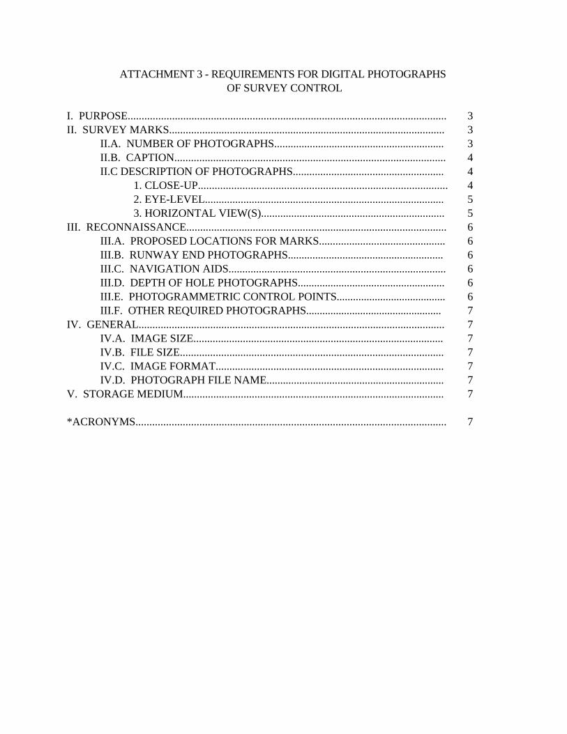
ATTACHMENT 3 - REQUIREMENTS FOR DIGITAL PHOTOGRAPHS OF SURVEY CONTROL
I. PURPOSE................................................................................................................... 3II. SURVEY MARKS.................................................................................................... 3
II.A. NUMBER OF PHOTOGRAPHS.............................................................. 3II.B. CAPTION.................................................................................................. 4II.C DESCRIPTION OF PHOTOGRAPHS....................................................... 4
1. CLOSE-UP.......................................................................................... 42. EYE-LEVEL....................................................................................... 53. HORIZONTAL VIEW(S)................................................................... 5
III. RECONNAISSANCE.............................................................................................. 6III.A. PROPOSED LOCATIONS FOR MARKS.............................................. 6III.B. RUNWAY END PHOTOGRAPHS......................................................... 6III.C. NAVIGATION AIDS............................................................................... 6III.D. DEPTH OF HOLE PHOTOGRAPHS...................................................... 6III.E. PHOTOGRAMMETRIC CONTROL POINTS........................................ 6III.F. OTHER REQUIRED PHOTOGRAPHS.................................................. 7
IV. GENERAL............................................................................................................... 7IV.A. IMAGE SIZE........................................................................................... 7IV.B. FILE SIZE................................................................................................ 7IV.C. IMAGE FORMAT................................................................................... 7IV.D. PHOTOGRAPH FILE NAME................................................................. 7
V. STORAGE MEDIUM............................................................................................... 7
*ACRONYMS................................................................................................................ 7
Page 3
ATTACHMENT 3 - REQUIREMENTS FOR DIGITAL PHOTOGRAPHS OF SURVEYCONTROL
I. PURPOSE - This document describes digital photographic standards for images of survey marks thatwill be stored in the National Geodetic Survey (NGS) database and for other reconnaissancephotographs. Since many of these images will be in the NGS database and available to the public, thesubject matter (survey equipment, personnel, background, etc.) must be in good taste and professionalin nature.
Digital photographs are useful for station (mark) reconnaissance, mark recovery, mark stabilityassessment, quality control, and as an aid during data processing and data verification. Some projectsmay require digital photographs during several stages of the project. Generally three photographs perstation will be stored in the NGS database, which will make them accessible to future users. The tablebelow summarizes the required photographs. Detailed descriptions of the photographs follow.
II. SURVEY MARK PHOTOGRAPHS - Take all photographs during daylight hours.
II A. NUMBER OF PHOTOGRAPHS - At least three digital photographs are required for each markrecovered or described during the current project. This means marks for which a written, NGS format,digital description or recovery note was prepared. The three photographs are described as numbers:(1) extreme close-up, (2) eye-level (5-6 feet distant), and (3) horizontal view (approx. 10-30 feetdistant). All three photographs require a digital caption and the correct file name. Photographs 2 and 3require a small, temporary sign in the photograph.
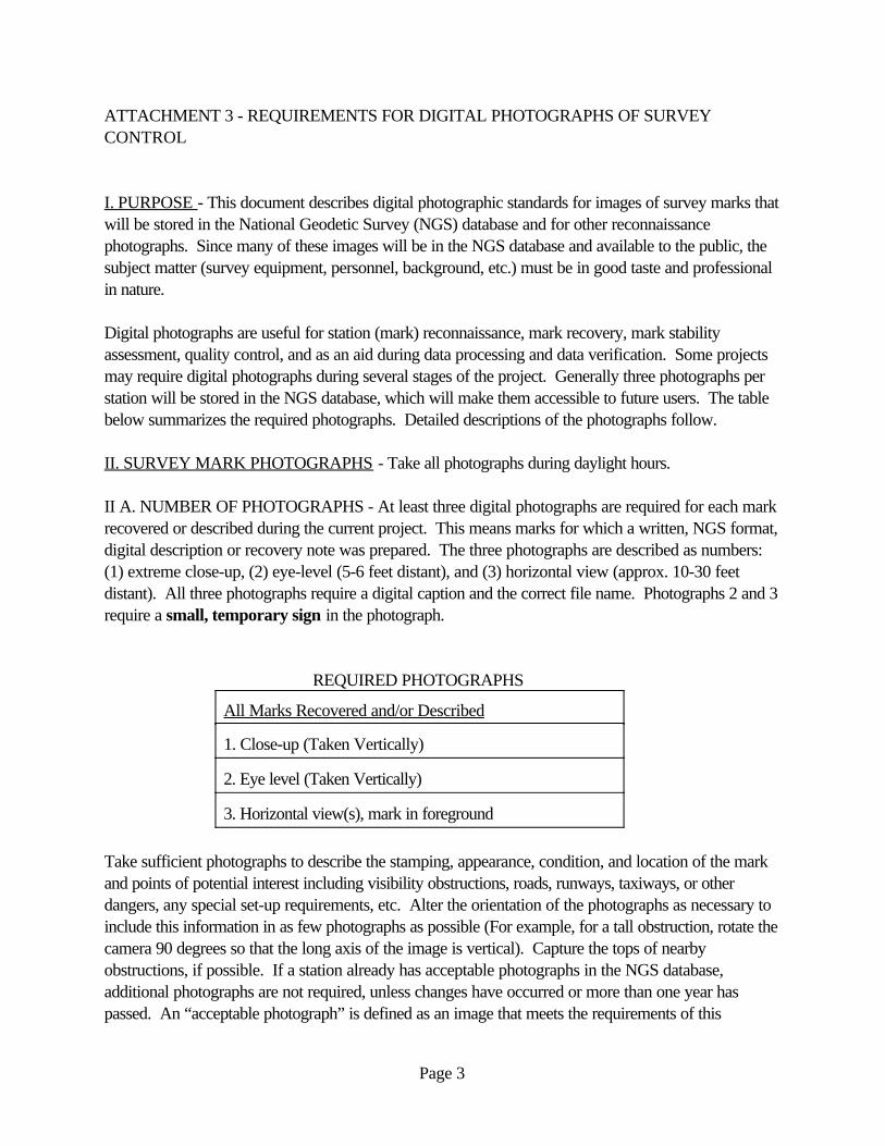
REQUIRED PHOTOGRAPHS
All Marks Recovered and/or Described
1. Close-up (Taken Vertically)
2. Eye level (Taken Vertically)
3. Horizontal view(s), mark in foreground
Take sufficient photographs to describe the stamping, appearance, condition, and location of the markand points of potential interest including visibility obstructions, roads, runways, taxiways, or otherdangers, any special set-up requirements, etc. Alter the orientation of the photographs as necessary toinclude this information in as few photographs as possible (For example, for a tall obstruction, rotate thecamera 90 degrees so that the long axis of the image is vertical). Capture the tops of nearbyobstructions, if possible. If a station already has acceptable photographs in the NGS database,additional photographs are not required, unless changes have occurred or more than one year haspassed. An “acceptable photograph” is defined as an image that meets the requirements of this
Page 4
document, is of good visual quality, and that no changes have taken place that a new photograph wouldhelp clarify.
II B. CAPTION - The photographer shall write a caption for each photograph. The caption shouldcontain the following comma-separated information:
- Station designation (name),- Station Permanent IDentifier (PID), for existing stations in the NGS database, leave blank ifnew station, - Airport Location IDentifier (LID), if on airport, leave blank if not on airport,- Photo number with cardinal direction (N, NE, E, SE, etc) that the camera is pointing, onlyphoto #3 has a direction- Station type (i.e. PACS, SACS, FBN, CBN), otherwise leave blank- Date photo was taken (ddMMMyyyy).
SAMPLE CAPTION FOR NEW MARK
JONES, 2, 8JAN2001
SAMPLE CAPTION FOR EXISTING PACS ON AIRPORT
SMITH, AB1234, LAX, 3N, PACS, 8JAN2001
Note, the cardinal direction should not be included on photographs 1 and 2 since they were takenvertically.
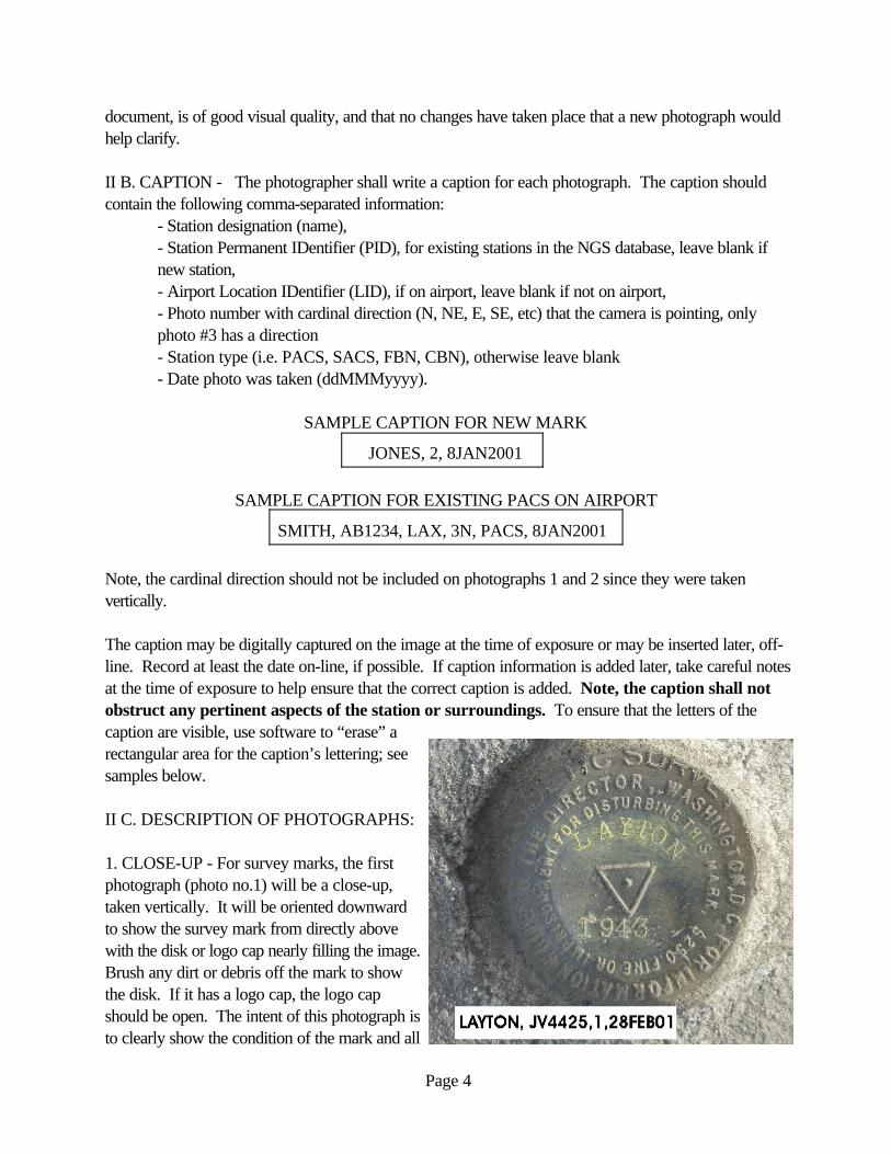
The caption may be digitally captured on the image at the time of exposure or may be inserted later, off-line. Record at least the date on-line, if possible. If caption information is added later, take careful notesat the time of exposure to help ensure that the correct caption is added. Note, the caption shall notobstruct any pertinent aspects of the station or surroundings. To ensure that the letters of thecaption are visible, use software to “erase” arectangular area for the caption’s lettering; seesamples below.
II C. DESCRIPTION OF PHOTOGRAPHS:
1. CLOSE-UP - For survey marks, the firstphotograph (photo no.1) will be a close-up,taken vertically. It will be oriented downwardto show the survey mark from directly abovewith the disk or logo cap nearly filling the image. Brush any dirt or debris off the mark to showthe disk. If it has a logo cap, the logo capshould be open. The intent of this photograph isto clearly show the condition of the mark and all
Page 5
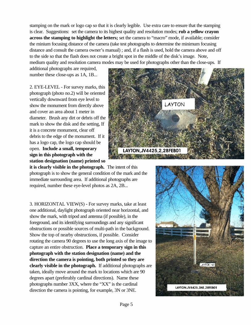
stamping on the mark or logo cap so that it is clearly legible. Use extra care to ensure that the stampingis clear. Suggestions: set the camera to its highest quality and resolution modes; rub a yellow crayonacross the stamping to highlight the letters; set the camera to “macro” mode, if available; considerthe minium focusing distance of the camera (take test photographs to determine the minimum focusingdistance and consult the camera owner’s manual) ; and, if a flash is used, hold the camera above and offto the side so that the flash does not create a bright spot in the middle of the disk’s image. Note,medium quality and resolution camera modes may be used for photographs other than the close-ups. Ifadditional photographs are required,number these close-ups as 1A, 1B...
2. EYE-LEVEL - For survey marks, thisphotograph (photo no.2) will be orientedvertically downward from eye level toshow the monument from directly aboveand cover an area about 1 meter indiameter. Brush any dirt or debris off themark to show the disk and the setting, Ifit is a concrete monument, clear offdebris to the edge of the monument. If ithas a logo cap, the logo cap should beopen. Include a small, temporarysign in this photograph with thestation designation (name) printed soit is clearly visible in the photograph. The intent of thisphotograph is to show the general condition of the mark and theimmediate surrounding area. If additional photographs arerequired, number these eye-level photos as 2A, 2B...
3. HORIZONTAL VIEW(S) - For survey marks, take at leastone additional, daylight photograph oriented near horizontal, andshow the mark, with tripod and antenna (if possible), in theforeground, and its identifying surroundings and any significantobstructions or possible sources of multi-path in the background. Show the top of nearby obstructions, if possible. Considerrotating the camera 90 degrees to use the long axis of the image tocapture an entire obstruction. Place a temporary sign in thisphotograph with the station designation (name) and thedirection the camera is pointing, both printed so they areclearly visible in the photograph. If additional photographs aretaken, ideally move around the mark to locations which are 90degrees apart (preferably cardinal directions). Name thesephotographs number 3XX, where the “XX” is the cardinaldirection the camera is pointing, for example, 3N or 3NE.
Page 6
II D. FILE NAMES - See Section IV D.
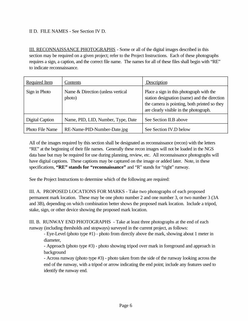
III. RECONNAISSANCE PHOTOGRAPHS - Some or all of the digital images described in thissection may be required on a given project; refer to the Project Instructions. Each of these photographsrequires a sign, a caption, and the correct file name. The names for all of these files shall begin with “RE”to indicate reconnaissance.
Required Item Contents Description
Sign in Photo Name & Direction (unless verticalphoto)
Place a sign in this photograph with thestation designation (name) and the directionthe camera is pointing, both printed so theyare clearly visible in the photograph.
Digital Caption Name, PID, LID, Number, Type, Date See Section II.B above
Photo File Name RE-Name-PID-Number-Date.jpg See Section IV.D below
All of the images required by this section shall be designated as reconnaissance (recon) with the letters“RE” at the beginning of their file names. Generally these recon images will not be loaded in the NGSdata base but may be required for use during planning, review, etc. All reconnaissance photographs willhave digital captions. These captions may be captured on the image or added later. Note, in thesespecifications, “RE” stands for “reconnaissance” and “R” stands for “right” runway. See the Project Instructions to determine which of the following are required:
III. A. PROPOSED LOCATIONS FOR MARKS - Take two photographs of each proposedpermanent mark location. These may be one photo number 2 and one number 3, or two number 3 (3Aand 3B), depending on which combination better shows the proposed mark location. Include a tripod,stake, sign, or other device showing the proposed mark location.
III. B. RUNWAY END PHOTOGRAPHS - Take at least three photographs at the end of eachrunway (including thresholds and stopways) surveyed in the current project, as follows:
- Eye-Level (photo type #1) - photo from directly above the mark, showing about 1 meter indiameter,- Approach (photo type #3) - photo showing tripod over mark in foreground and approach inbackground - Across runway (photo type #3) - photo taken from the side of the runway looking across theend of the runway, with a tripod or arrow indicating the end point; include any features used toidentify the runway end.
Page 7
III. C. NAVIGATION AIDS (NAVAIDS) - Take photo(s) (type #3) of all NAVAIDS surveyed. Show the survey tripod in place to indicate the exact point surveyed, or if positioned remotely, addarrows and labels to the photograph indicating the horizontal and/or vertical point(s) surveyed.
III. D. DEPTH OF HOLE PHOTOGRAPHS - Take at least one photograph showing the hole dug ordrilled for a concrete or rod mark. Place a measuring device (e.g., tape measure or level rod) in the hole,clearly showing the depth of the hole.
III.E. PHOTOGRAMMETRIC CONTROL POINTS (Paneled and photo identified) - Take twonumber 3 type photographs of all photogrammetric control points clearly showing the point. Thesephotos will be used later as an aid in identifying the point on the aerial photographs. Show the mark in theforeground and the nearest identifiable feature in the background. The two photographs should be takenfrom two different directions, ideally 90 degrees apart (such as from the East and the South).
III.F. OTHER REQUIRED PHOTOGRAPHS - as may be required by other instructions.
IV. GENERAL:IV A. IMAGE SIZE - Each image should be about 800 by 1000 pixels when submitted.
IV B. 2. FILE SIZE - Maximum file size for each image is 500 KB, typical file size should be about 50 -100KB.
IV C. IMAGE FORMAT - Store the digital photographs in JPEG format, approximately 50% reduction.
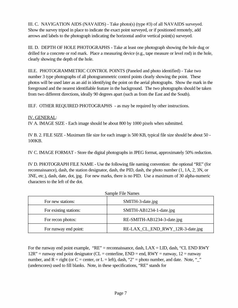
IV D. PHOTOGRAPH FILE NAME - Use the following file naming convention: the optional “RE” (forreconnaissance), dash, the station designator, dash, the PID, dash, the photo number (1, 1A, 2, 3N, or3NE, etc.), dash, date, dot, jpg. For new marks, there is no PID. Use a maximum of 30 alpha-numericcharacters to the left of the dot.
Sample File Names
For new stations: SMITH-3-date.jpg
For existing stations: SMITH-AB1234-1-date.jpg
For recon photos: RE-SMITH-AB1234-3-date.jpg
For runway end point: RE-LAX_CL_END_RWY_12R-3-date.jpg
For the runway end point example, “RE” = reconnaissance, dash, LAX = LID, dash, “CL END RWY12R” = runway end point designator (CL = centerline, END = end, RWY = runway, 12 = runwaynumber, and R = right (or C = center, or L = left), dash, “2" = photo number, and date. Note, “_”(underscores) used to fill blanks. Note, in these specifications, “RE” stands for

Page 8
“reconnaissance” and “R” stands for “right” runway (used if there is a parallel set of runways). Also, theLID may be four characters rather than just three.
V. STORAGE MEDIUM - Submit all digital photos together on their own medium (CD), not on thesame medium with other types of data. For airport work, submit all photos for a given airport in asubdirectory named for that airport.
*Aconyms:PACS - Primary Airport Control StationSACS - Secondary Airport Control StationFBN - Federal Base NetworkCORS - Continuously Operating Reference Station (Global Positioning System receiver)CBN - Cooperative Base NetworkRM - Reference Mark
ATTACHMENT 4STATION LOCATION SKETCH AND
VISIBILITY DIAGRAM
TOGENERAL GUIDANCE AND SPECIFICATIONS FOR
AERONAUTICAL SURVEYS VOLUME A
FEDERAL AVIATION ADMINISTRATIONAIRPORT SURVEYS
Location / Airport Nameand ID________________________________________________ Project _______________________
Station Designation _____________________________________ PID____________ Date__________
Circle all applicable: Observer & PACS SACS BM FBN CBN OTHER___________ Organization_______________________________________
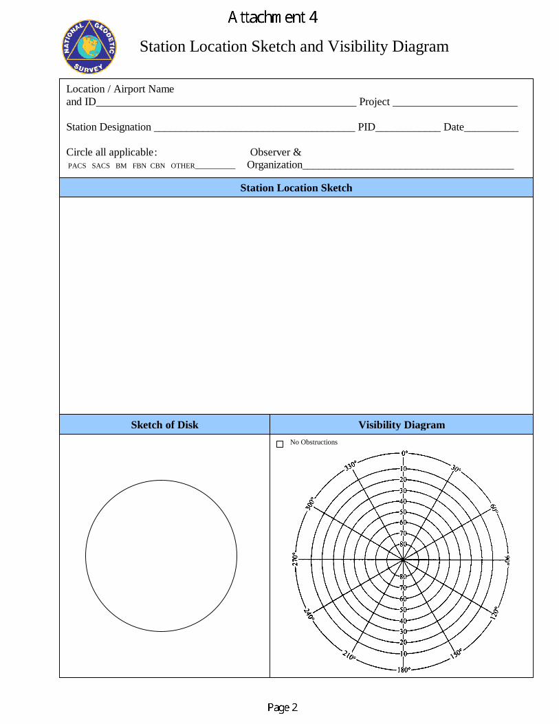
Station Location Sketch and Visibility Diagram
No Obstructions
Sketch of Disk Visibility Diagram
Station Location Sketch


December 11, 2003
ATTACHMENT 5WRITING STATION DESCRIPTIONS AND RECOVERY
NOTES WITH WDDPROC
TOGENERAL GUIDANCE AND SPECIFICATIONS FOR
AERONAUTICAL SURVEYS VOLUME A
FEDERAL AVIATION ADMINISTRATIONAIRPORT SURVEYS

Page 2
WRITING STATION DESCRIPTIONS AND RECOVERY NOTES WITH WDDPROC
Descriptions are one of the end products of surveying, along with the positions and the surveymarks themselves. All three shall be of highest quality. The descriptions must be complete,accurate and in standardized format if the station is to be reliably and easily recovered for use in thefuture. Descriptions shall be in the standard NGS format of three paragraphs as described below under"Description Format."
1.0 GENERAL
1.1 DEFINITION OF DESCRIPTION VS. RECOVERY NOTEa. A description details the location of a new survey mark, or one not previously in the NGSdigital database. b. A recovery note is an update and/or refinement to a description already in the NGS digitaldatabase, written upon a return visit to a survey mark.
1.2 LEVELS OF COMPLEXITY OF RECOVERY NOTESa. No Changes - If an existing station’s digital description is complete, accurate, and meetsBlue Book requirements, the station may be recovered with a brief recovery note, such as"RECOVERED AS DESCRIBED."
b. Minor Changes - If minor changes or additions to the description are required, they may beadded after the above phrase, such as "RECOVERED AS DESCRIBED, EXCEPT A NEWWOODEN FENCE IS NOW 3 METERS NORTH OF THE STATION." See typical caseslisted below.
c. Major Changes - Where major changes have occurred, major inaccuracies are found, orwhere required information is missing (in any portion of the description), a complete three-paragraph recovery note, with the same format as a new description, is required. If ameasurement discrepancy is found, state that the new distance was verified, for example, bytaping in both English units and metric units or by two separate measurements by two differentpeople. See typical cases listed below.
d. Exemption - If a recovery note has been written for the station within one year and nochanges have taken place, a new recovery note is not required. Note, this may cause an errormessage in the description checking software, which may be ignored.
1.3 SOFTWARE - Descriptions and Recovery notes must be properly encoded into a D-file by usingNGS WDDPROC software. Please refer to the NGS Web site: http://www.ngs.noaa.gov/FGCS/BlueBook/, Annex P (Geodetic Control Descriptive Data), forinformation. Note, WDDPROC is used for both new Descriptions and for Recovery Notes.
Page 3
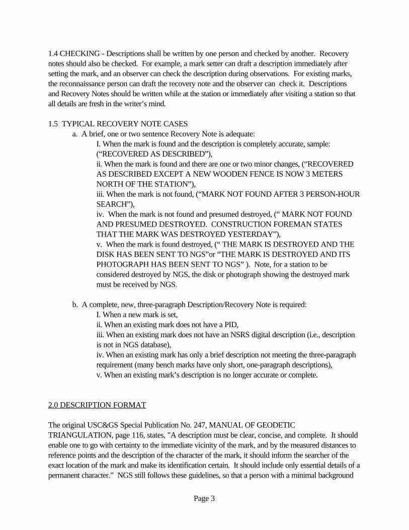
1.4 CHECKING - Descriptions shall be written by one person and checked by another. Recoverynotes should also be checked. For example, a mark setter can draft a description immediately aftersetting the mark, and an observer can check the description during observations. For existing marks,the reconnaissance person can draft the recovery note and the observer can check it. Descriptionsand Recovery Notes should be written while at the station or immediately after visiting a station so thatall details are fresh in the writer’s mind.
1.5 TYPICAL RECOVERY NOTE CASESa. A brief, one or two sentence Recovery Note is adequate:
I. When the mark is found and the description is completely accurate, sample:(“RECOVERED AS DESCRIBED”), ii. When the mark is found and there are one or two minor changes, (“RECOVEREDAS DESCRIBED EXCEPT A NEW WOODEN FENCE IS NOW 3 METERSNORTH OF THE STATION”),iii. When the mark is not found, (“MARK NOT FOUND AFTER 3 PERSON-HOURSEARCH”),iv. When the mark is not found and presumed destroyed, (“ MARK NOT FOUNDAND PRESUMED DESTROYED. CONSTRUCTION FOREMAN STATESTHAT THE MARK WAS DESTROYED YESTERDAY”),v. When the mark is found destroyed, (“ THE MARK IS DESTROYED AND THEDISK HAS BEEN SENT TO NGS”or “THE MARK IS DESTROYED AND ITSPHOTOGRAPH HAS BEEN SENT TO NGS” ). Note, for a station to beconsidered destroyed by NGS, the disk or photograph showing the destroyed markmust be received by NGS.
b. A complete, new, three-paragraph Description/Recovery Note is required: I. When a new mark is set,ii. When an existing mark does not have a PID, iii. When an existing mark does not have an NSRS digital description (i.e., descriptionis not in NGS database),iv. When an existing mark has only a brief description not meeting the three-paragraphrequirement (many bench marks have only short, one-paragraph descriptions),v. When an existing mark’s description is no longer accurate or complete.
2.0 DESCRIPTION FORMAT
The original USC&GS Special Publication No. 247, MANUAL OF GEODETICTRIANGULATION, page 116, states, "A description must be clear, concise, and complete. It shouldenable one to go with certainty to the immediate vicinity of the mark, and by the measured distances toreference points and the description of the character of the mark, it should inform the searcher of theexact location of the mark and make its identification certain. It should include only essential details of apermanent character.” NGS still follows these guidelines, so that a person with a minimal background

Page 4
in surveying and no local geographic or historical knowledge can easily find the mark by logicallyfollowing the text of the description.
2.1 FIRST PARAGRAPH - The first paragraph is the description of locality. This part of thedescription begins by referring to the airline distance and direction (cardinal or inter-cardinal point of thecompass) from the three nearest well-known mapped geographic feature(s), usually the nearest citiesor towns. Use three references equally spaced around the horizon, if possible. In writing theDescription, always progress from the farthest to the nearest reference point. Distances in thispart of the description shall be in kilometers (followed by miles), or meters (followed by feet), alldistances to one decimal place. Detailed measurements which appear elsewhere in the descriptionshould not be repeated in this paragraph. Points of the compass should be fully spelled out. Do not usebearings or azimuths. State the name, address, and phone number of public sector property owners(however, phone numbers of private property owners are NOT included ). State any advance noticeand security access requirements for reaching the station. Also state any unusual transportationmethods that may be required to reach the station.Sample first paragraph:
“STATION IS LOCATED ABOUT 12.9 KM (8.0 MILES) SOUTHWEST OF EASTON,ABOUT 6.4 KM (4.0 MILES) NORTHWEST OF CAMBRIDGE, AND ABOUT 3.6 KM(2.2MILES) EAST OF SMITHVILLE ON PROPERTY OWNED BY MR. H.P. LAYTON,AND KNOWN AS OLD GOVERNOR JACKSONS ESTATE.”
2.2 SECOND PARAGRAPH - The second paragraph contains the directions to reach the station. This section is one of the most useful parts of a description. It usually enables a stranger to go directlyto a station without a delay due to a detailed study of maps or of making local inquiries. It is a routedescription which should start from a definite point, such as (a) the nearest intersection of named ornumbered main highways (ideally Interstate and U.S. highways, or at least those which are shown oncommonly used road maps), and approximately where that intersection is, or (b) some definite andwell-known geographical feature (eg. main post office or county courthouse) and give its name andgeneral location. Odometer distances shall be given to tenths of kilometers (followed by tenths ofmiles). For roads with names and numbers, give both in the first occurrence.
a. The format for the first leg of the “to reach” is:I. FROM THE MAIN POST OFFICE IN DOWNTOWN SMITHVILLE, orI. FROM THE INTERSECTION OF INTERSTATE XX AND STATE HIGHWAYYY, ABOUT 3 MI NORTH OF SMITHVILLE,ii. GO A DIRECTION (north, northeast, northerly, northeasterly, etc.),iii. ON A ROAD (name or number of road or highway),iv. FOR A DISTANCE (km followed by miles in parentheses),v. TO SOMETHING (intersection, or fork in road, or T-road left or T-road right).
Page 5
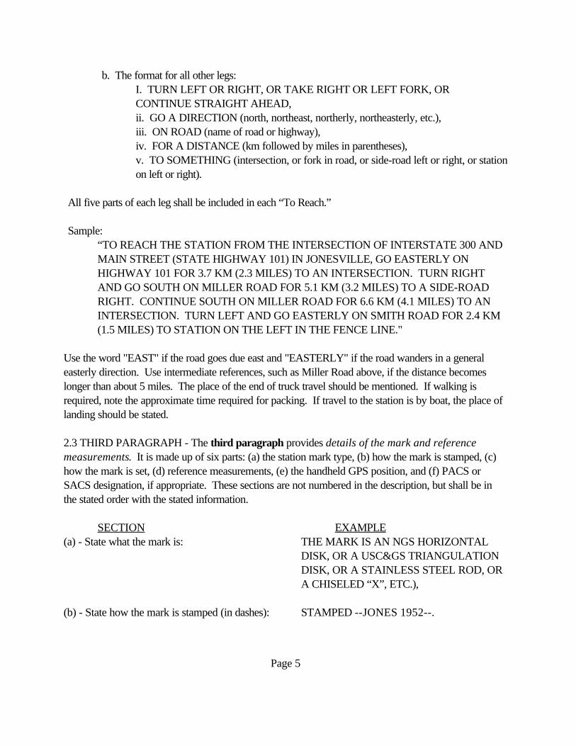
b. The format for all other legs:I. TURN LEFT OR RIGHT, OR TAKE RIGHT OR LEFT FORK, ORCONTINUE STRAIGHT AHEAD,ii. GO A DIRECTION (north, northeast, northerly, northeasterly, etc.),iii. ON ROAD (name of road or highway),iv. FOR A DISTANCE (km followed by miles in parentheses),v. TO SOMETHING (intersection, or fork in road, or side-road left or right, or stationon left or right).
All five parts of each leg shall be included in each “To Reach.”
Sample:“TO REACH THE STATION FROM THE INTERSECTION OF INTERSTATE 300 ANDMAIN STREET (STATE HIGHWAY 101) IN JONESVILLE, GO EASTERLY ONHIGHWAY 101 FOR 3.7 KM (2.3 MILES) TO AN INTERSECTION. TURN RIGHTAND GO SOUTH ON MILLER ROAD FOR 5.1 KM (3.2 MILES) TO A SIDE-ROADRIGHT. CONTINUE SOUTH ON MILLER ROAD FOR 6.6 KM (4.1 MILES) TO AN INTERSECTION. TURN LEFT AND GO EASTERLY ON SMITH ROAD FOR 2.4 KM(1.5 MILES) TO STATION ON THE LEFT IN THE FENCE LINE."
Use the word "EAST" if the road goes due east and "EASTERLY" if the road wanders in a generaleasterly direction. Use intermediate references, such as Miller Road above, if the distance becomeslonger than about 5 miles. The place of the end of truck travel should be mentioned. If walking isrequired, note the approximate time required for packing. If travel to the station is by boat, the place oflanding should be stated.
2.3 THIRD PARAGRAPH - The third paragraph provides details of the mark and referencemeasurements. It is made up of six parts: (a) the station mark type, (b) how the mark is stamped, (c)how the mark is set, (d) reference measurements, (e) the handheld GPS position, and (f) PACS orSACS designation, if appropriate. These sections are not numbered in the description, but shall be inthe stated order with the stated information.
SECTION EXAMPLE(a) - State what the mark is: THE MARK IS AN NGS HORIZONTAL
DISK, OR A USC&GS TRIANGULATIONDISK, OR A STAINLESS STEEL ROD, ORA CHISELED “X”, ETC.),
(b) - State how the mark is stamped (in dashes): STAMPED --JONES 1952--.
Page 6
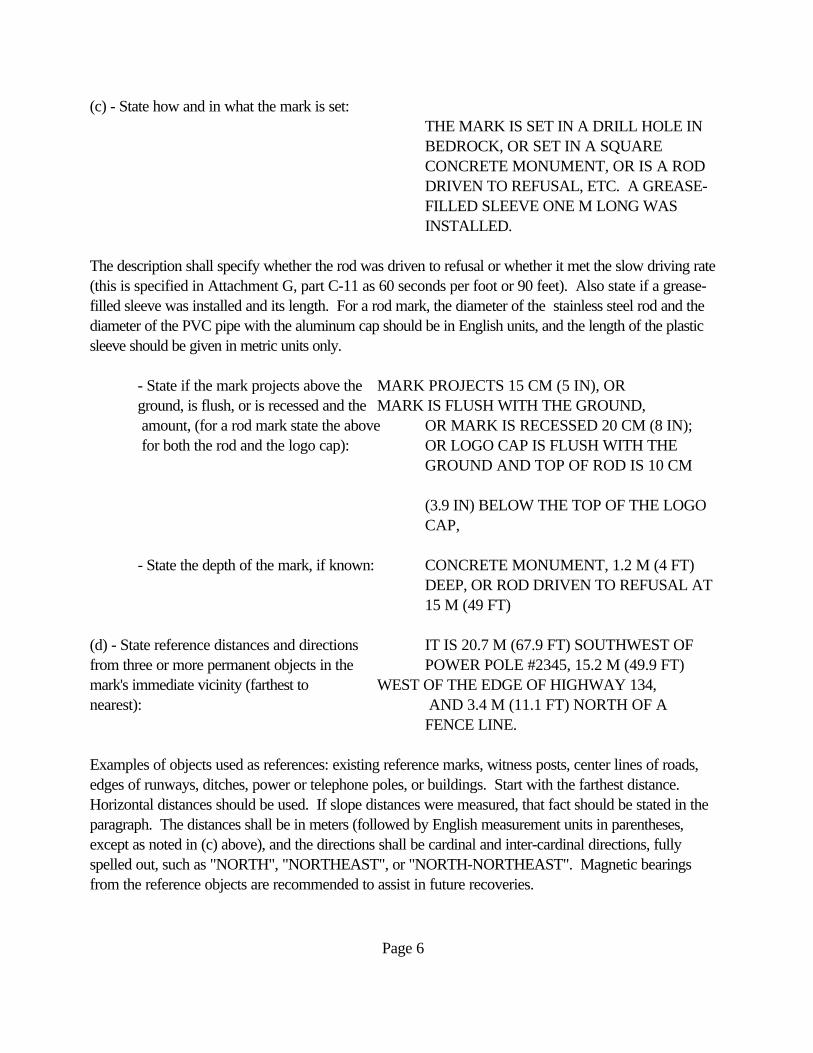
(c) - State how and in what the mark is set:THE MARK IS SET IN A DRILL HOLE INBEDROCK, OR SET IN A SQUARECONCRETE MONUMENT, OR IS A RODDRIVEN TO REFUSAL, ETC. A GREASE-FILLED SLEEVE ONE M LONG WASINSTALLED.
The description shall specify whether the rod was driven to refusal or whether it met the slow driving rate(this is specified in Attachment G, part C-11 as 60 seconds per foot or 90 feet). Also state if a grease-filled sleeve was installed and its length. For a rod mark, the diameter of the stainless steel rod and thediameter of the PVC pipe with the aluminum cap should be in English units, and the length of the plasticsleeve should be given in metric units only.
- State if the mark projects above the MARK PROJECTS 15 CM (5 IN), OR ground, is flush, or is recessed and the MARK IS FLUSH WITH THE GROUND,
amount, (for a rod mark state the above OR MARK IS RECESSED 20 CM (8 IN); for both the rod and the logo cap): OR LOGO CAP IS FLUSH WITH THE
GROUND AND TOP OF ROD IS 10 CM
(3.9 IN) BELOW THE TOP OF THE LOGOCAP,
- State the depth of the mark, if known: CONCRETE MONUMENT, 1.2 M (4 FT)DEEP, OR ROD DRIVEN TO REFUSAL AT15 M (49 FT)
(d) - State reference distances and directions IT IS 20.7 M (67.9 FT) SOUTHWEST OFfrom three or more permanent objects in the POWER POLE #2345, 15.2 M (49.9 FT)mark's immediate vicinity (farthest to WEST OF THE EDGE OF HIGHWAY 134,nearest): AND 3.4 M (11.1 FT) NORTH OF A
FENCE LINE.
Examples of objects used as references: existing reference marks, witness posts, center lines of roads,edges of runways, ditches, power or telephone poles, or buildings. Start with the farthest distance. Horizontal distances should be used. If slope distances were measured, that fact should be stated in theparagraph. The distances shall be in meters (followed by English measurement units in parentheses,except as noted in (c) above), and the directions shall be cardinal and inter-cardinal directions, fullyspelled out, such as "NORTH", "NORTHEAST", or "NORTH-NORTHEAST". Magnetic bearingsfrom the reference objects are recommended to assist in future recoveries.
Page 7
(e) Provide a handheld GPS position for all new and recovered marks, and for all proposed marklocations. Include the handheld GPS position in both the scaled position field (in the top portion of thedigital description) and in the text, described hereafter. In the text, include the position and the accuracycode of HH1 or HH2, depending on the type of receiver used. HH1 stands for Hand-Held accuracycode 1 (differentially corrected, hand-held GPS), and HH2 stands for Hand-Held accuracy code 2(stand-alone, hand-held GPS), as follows:
Accuracy code 1 (HH1) = +/- 1-3 metersAccuracy code 2 (HH2) = +/- 10 meters
GPS Data Formats:
CODE LATITUDE LONGITUDE SECOND PLACESHH1 NDDMMSS.ss WDDDMMSS.ss (2 places of seconds)HH2 NDDMMSS.s WDDDMMSS.s (1 place of seconds)
Use “N” or “S” for latitude and “W” or “E” for longitude. Use three digits for the degrees of longitude.
(f) If the station is a Primary or Secondary Airport THIS STATION IS DESIGNATED Control Station mark, the third paragraph shall end AS A PRIMARY AIRPORT CONTROL with the appropriate designation of Primary or STATION.Secondary Airport Control Station):
Sample for a rod mark:
“THE STATION IS THE TOP-CENTER OF A 9/16 INCH STAINLESS STEEL ROD DRIVENTO REFUSAL DEPTH OF 18M. THE LOGO CAP IS STAMPED --SMITH 2003--. THE LOGOCAP IS MOUNTED ON A 5 IN DIAMETER PVC PIPE. A ONE M LONG GREASE-FILLEDSLEEVE WAS INSTALLED. LOGO CAP IS FLUSH WITH THE GROUND AND TOP OF RODIS 10 CM (3.9 IN) BELOW THE TOP OF THE LOGO CAP. THE MARK IS 32.4 METERS(101.74 FEET) NORTHEAST OF NORTHEAST CORNER OF THE HOUSE, 16.62 METERS(54.5 FEET) NORTH OF WATER PUMP ALONGSIDE OF HEDGE AROUND OLD FLOWERGARDEN, AND 4 METERS (12.96 FEET) NORTH OF NORTHEAST CORNER OF HIGHHEDGE ENCLOSING OLD FLOWER GARDEN. THE HH1 GPS IS: 304050.2N, 1201020.4W.”
Sample for a concrete monument:
“THE STATION IS AN NGS HORIZONTAL DISK, STAMPED --JONES 2003-- SET IN AROUND CONCRETE MONUMENT 1.2 M (4 FT) DEEP AND 0.3 M (12 IN) IN DIAMETER. ITIS SET FLUSH WITH THE GROUND. IT IS 32.4 METERS (101.74 FEET) NORTHEAST OFNORTHEAST CORNER OF THE HOUSE, 16.62 METERS (54.5 FEET) NORTH OF WATER
Page 8
PUMP ALONGSIDE OF HEDGE AROUND OLD FLOWER GARDEN, AND 4 METERS (12.96FEET) NORTH OF NORTHEAST CORNER OF HIGH HEDGE ENCLOSING OLD FLOWERGARDEN. THE HH1 GPS IS: 304050.2N, 1201020.4W.”
3.0 IMPORTANT POINTS REGARDING DESCRIPTIONS
3.1 NAMES - Use the station designation (name) and PID, exactly as listed in the NGSdatabase, in all survey records. Do not add dates, agency acronyms, or other information to thename, nor the stamping. Note, frequently the stamping and the official station designation are notthe same. For example, stampings include the year set, but designations generally do not.
3.2 TERMINOLOGY - Correct NGS survey terminology shall be used in all stationdescriptions and reports (see GEODETIC GLOSSARY, NGS, 1986).
3.3 DISTANCES - All measurements are assumed to be horizontal unless labeled “slope.” Distances measured from a line (e.g., the center-line of a road or a fence line) are assumed to bemeasured perpendicular to that line. The origin of measurements at the junction of two roads isassumed to be the intersection of center-lines of both roads. Measurements are assumed to befrom the center of an object (i.e. power pole) unless stated otherwise.
3.4 REPAIR - Any work done to repair a mark shall be described completely in the updatedrecovery note. Note, a repair strengthens the mark but must not change its position. Forexample, adding concrete or epoxy around a disk where some is missing is a repair.
3.5 REFERENCE MARK NAMES - Note, reference marks are abbreviated “RM x” indescriptions, but on "Reference Mark" disks they are stamped "NO. x".
3.6 WCHKDESC - Run the digital D-file through the WCHKDESC program (field-leveloption), one of several programs within the WDDPROC Software Suite, to identify format andcoding errors. This program is accessed by (a) running the WDDPROC program and (b)selecting the program, WCHKDESC, from the main menu.
3.7 METRIC CONVERSION - Use 3.2808333333 feet equals one meter.
3.8 ABBREVIATIONS - Meter = M, kilometer = KM, centimeter = CM, mile = MI, nauticalmile = NM, feet = FT, inch = IN.
4.0 THE WDESC PROGRAM
The WDESC program, one of several programs within the WDDPROC Software Suite (available overthe Web at http://www.ngs.noaa.gov/PC_PROD/DDPROC4.XX/ddproc.index.html), is used to encode

Page 9
descriptions and recovery notes in D-FILE format for the loading of these descriptions into the NGSdatabase. The NGS Blue Book and the WDESC documentation contain information for properlyencoding descriptions. Helpful information is contained in the following paragraphs.
When creating a description file, a backup file is automatically created. Every time a few descriptionsare entered, it would be best if they are checked with WCHKDESC and the file corrected. The backupshould be renamed before reopening the program or it will be overwritten. Always exit from theWDESC program from the pull-down File option Exit. It is recommended to save the description file asa new filename every time the program is exited; saving after each description is entered is alsorecommended.
Remember to enter “Y” into the satellite usage code field in the Header Record if the mark is suitable forGPS observations.
Set the condition code on the Description Header form as described in The Description ProcessingHandbook, Chapter 1, D-FILE Format (for Both Microsoft Windows 95/98/NT and UNIX):The Format of a Description File (D-FILE), which is available on the Web by downloadingdformat.htm from Section 4 of the WDDPROC page (http://www.ngs.noaa.gov/PC_PROD/DDPROC4.XX/ddproc.index.html).
Three separate paragraphs are required in the descriptive text field since they make the description mucheasier to read. Therefore, when entering the text into the Description Header form using the WDESCprogram, separate each paragraph by pressing the [ENTER] key on the keyboard to add a blank line atthe end of the first paragraph.
The FPR code is a field on the Description Header form in the WDESC program. Set the “FPR” fieldin the Description Header form to “F”, “P”, or “R”, for Flush, Projected, or Recessed, respectively. Inthe description, include the logo cap relationship to the ground surface (projecting above, flush with, orrecessed below), and include the distance that the top of the rod is below the top of the logo cap. It isimportant to include information regarding the exact placement of the logo cap for future reference.
A list of the proper agency codes for the WDDPROC Software Suite can be found on theNGS Web site in WDDPROC ANNEX C(http://www.ngs.noaa.gov/FGCS/BlueBook/annexc/annexc.index.html). The agency code to be usedfor marks that are set by the National Geodetic Survey is NGS. The agency code for marks set by theUSC&GS is CGS. Contractors shall use the code assigned to their company. If a contractor does nothave a code, a request for one should be emailed to: [email protected].
5.0 MARK TYPES
5.1 CONCRETE MARK - For a concrete mark set in accordance with the requirements ofAttachment E (http://www.ngs.noaa.gov/AERO/aerospecs.htm#vol1) use a setting code of"07". This classifies the station with a default vertical stability code of "C".

Page 10
5.2 ROD MARK GREATER THAN 4 METERS - For an NGS 3-D stainless steel rod markdriven to a depth of 4 meters or GREATER, use a monumentation code of "F" and a settingcode of "59". This classifies the station with a default vertical stability code of "A". Note, ifthe standard one meter plastic sleeve is used, the vertical stability code must be downgraded to“B”.
5.3 ROD MARKS LESS THAN 4 METERS ARE GENERALLY NOT ACCEPTABLE,see “Geodetic Bench Marks,” page 27, Table 3.
5.4 DISK IN ROCK OUTCROP - For a disk that is set in solid rock outcrop, use amonumentation code of "DH" or "DD" and a setting code of "66". This classifies the stationwith a default vertical stability code of "B".
Check the listing of valid monumentation codes and setting codes in The Description ProcessingHandbook, Chapter 1, D-FILE Format (for Both Microsoft Windows 95/98/NT and UNIX):The Format of a Description File (D-FILE), which is available on the Web in Annex P of the bluebook (http://www.ngs.noaa.gov/FGCS/BlueBook/), for the proper codes to use for other types ofmarks.Again, refer to the complete directions available at the Web site for using the NGS software packageWDDPROC to write the required station descriptions, and be sure to check your final product withWCHKDESC.
ATTACHMENT 6SAMPLE STATION TABLE (BLANK & FILLED-IN)
TOGENERAL GUIDANCE AND SPECIFICATIONS FOR
AERONAUTICAL SURVEYS VOLUME A
FEDERAL AVIATION ADMINISTRATIONAIRPORT SURVEYS
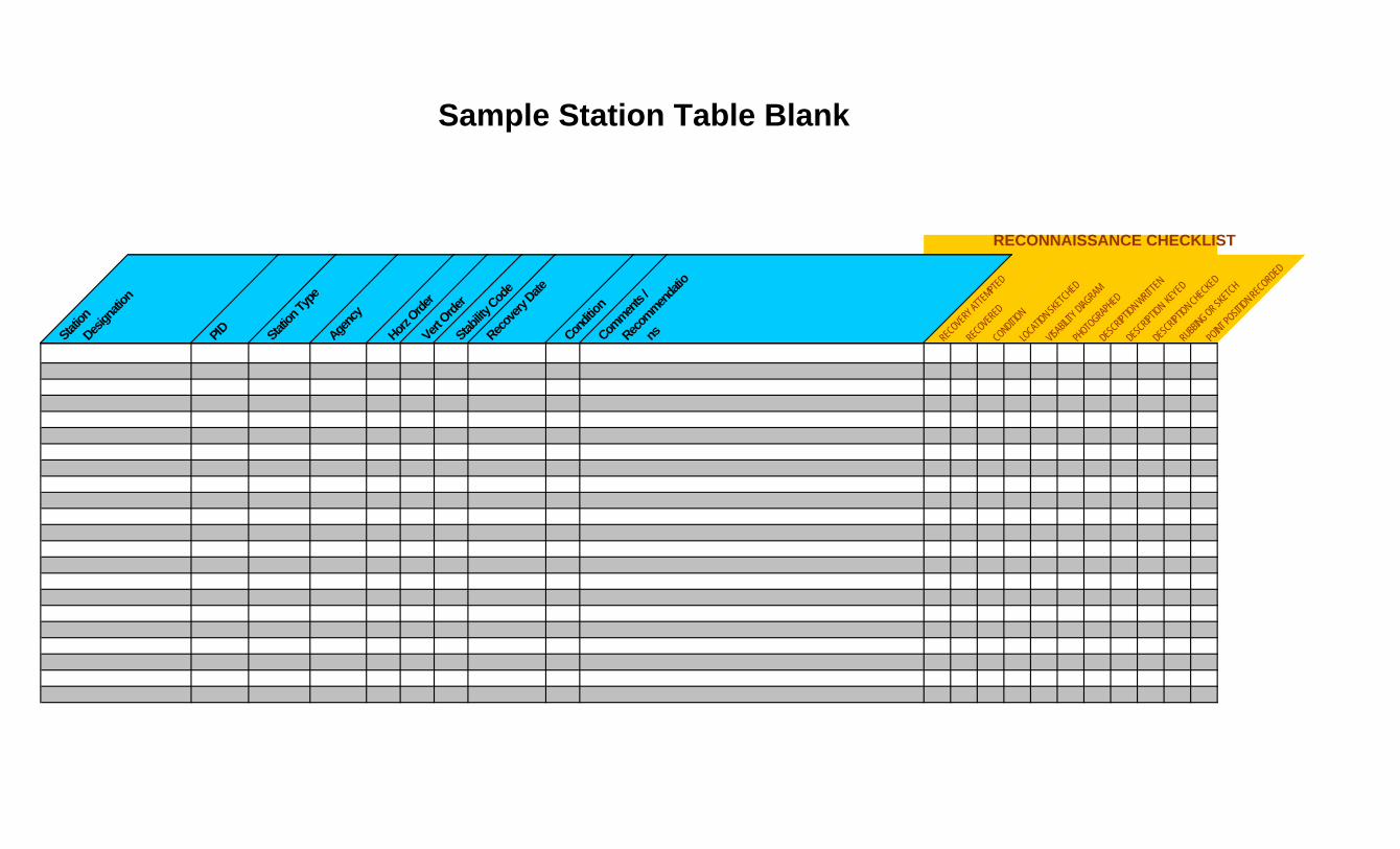
Sample Station Table Blank
RECONNAISSANCE CHECKLIST
Station
Design
ation
PID Station
Type
Agenc
y
Horz O
rder
Vert O
rder
Stabilit
y Cod
e
Recov
ery D
ate
Condit
ion
Commen
ts /
Recom
menda
tio
ns RECOVE
RY ATTE
MPTED
RECOVE
RED
CONDITION
LOCAT
ION SKET
CHED
VISAB
ILITY D
IAGRAM
PHOTO
GRAPHED
DESCRIPT
ION WRITT
EN
DESCRIPT
ION KEY
ED
DESCRIPT
ION CHECKE
D
RUBBING OR SK
ETCH
POINT P
OSITION REC
ORDED
Attachment 6 Sample Station Table
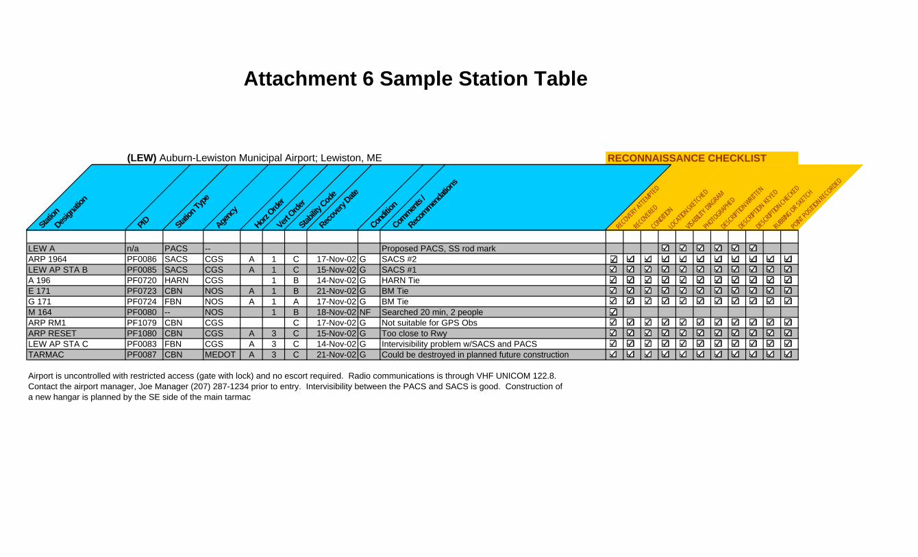
(LEW) Auburn-Lewiston Municipal Airport; Lewiston, ME RECONNAISSANCE CHECKLIST
Station
Design
ation
PID Station
Type
Agenc
y
Horz O
rder
Vert O
rder
Stabilit
y Cod
e
Recov
ery D
ate
Condit
ion
Commen
ts /
Recom
menda
tions
RECOVE
RY ATTE
MPTED
RECOVE
RED
CONDITION
LOCAT
ION SKET
CHED
VISAB
ILITY D
IAGRAM
PHOTO
GRAPHED
DESCRIPT
ION WRITT
EN
DESCRIPT
ION KEY
ED
DESCRIPT
ION CHECKE
D
RUBBING OR SK
ETCH
POINT P
OSITION REC
ORDED
LEW A n/a PACS -- Proposed PACS, SS rod markARP 1964 PF0086 SACS CGS A 1 C 17-Nov-02 G SACS #2LEW AP STA B PF0085 SACS CGS A 1 C 15-Nov-02 G SACS #1A 196 PF0720 HARN CGS 1 B 14-Nov-02 G HARN TieE 171 PF0723 CBN NOS A 1 B 21-Nov-02 G BM TieG 171 PF0724 FBN NOS A 1 A 17-Nov-02 G BM TieM 164 PF0080 -- NOS 1 B 18-Nov-02 NF Searched 20 min, 2 peopleARP RM1 PF1079 CBN CGS C 17-Nov-02 G Not suitable for GPS ObsARP RESET PF1080 CBN CGS A 3 C 15-Nov-02 G Too close to RwyLEW AP STA C PF0083 FBN CGS A 3 C 14-Nov-02 G Intervisibility problem w/SACS and PACSTARMAC PF0087 CBN MEDOT A 3 C 21-Nov-02 G Could be destroyed in planned future construction
Airport is uncontrolled with restricted access (gate with lock) and no escort required. Radio communications is through VHF UNICOM 122.8.Contact the airport manager, Joe Manager (207) 287-1234 prior to entry. Intervisibility between the PACS and SACS is good. Construction ofa new hangar is planned by the SE side of the main tarmac