at&t enhanced push-to-talk & land mobile radio … · at&t enhanced push-to-talk &...
TRANSCRIPT

The interface method is an IP link between the EPTT server and the radios. The radios are connected with a Radio-to-IP (RoIP) interface device that transfers audio and control signals between the radio and the EPTT system.
The interface devices are proven designs from JPS Interoperability Solutions. The technology was pioneered over 15 years ago, and has been consistently upgraded to include the radio interface algorithms that have made JPS the leader in radio interoperability. The devices employ a Radio-over-IP (RoIP protocol that was created and optimized for use with radio systems, taking into account the major differences between LMR and typical Voice over IP (VoIP) connections. It includes provisions for radio control signals and considers the delays inherent with LMR systems, with multiple codecs to allow optimization of the network link; balancing audio fidelity and tone integrity requirements with available bandwidth.
JPS Interoperability Solutions’ NXU-2A Radio-to-RoIP Interface
There are over 12,000 NXU-2A standalone RoIP interfaces currently in operation. In addition, JPS has sold over 8,800 radio interoperability gateways; most, such as the ACU-2000 described later in this document, are capable of multiple RoIP interfaces. These gateways and the RoIP capability are key components of a number of statewide radio interoperability systems used daily for Public Safety communications.
This document explains the basic concepts related to interfacing AT&T Enhanced Push-To-Talk over Cellular (EPTT) with Land Mobile Radio (LMR). On the EPTT side, the capability allows radio channels or talkgroups to appear just like any other EPTT member, with the ability to be included in Push-to-Talk conversations in the same manner as any EPTT user. On the radio side, whenever a radio user begins a transmission on a radio that has been configured in a EPTT talkgroup, that user’s audio is sent to not only the other radios on that channel, but also to any EPTT users in the associated EPTT talkgroup. Likewise, all radio users on that radio channel will hear any audio from associated EPTT talkgroup members.
AT&T Enhanced Push-To-Talk & Land Mobile Radio Integration via RoIP Technology from JPS
Interoperability Solutions

PTT+LMR Explanation Page 2 of 13 Rev 3 – August 2016
It's important to note that most LMR radios, unlike most telephones, cannot transmit (talk) and receive (listen) at the same time. They can only do one or the other (this is called half duplex). This same is true for an EPTT system. A person will pick up their radio (or EPTT phone) and begin talking. Other system users on the same frequency (or talkgroup) can hear, but can’t respond until the initial transmission has ended.
The essential point to remember is that, for the half-duplex systems described in this document, when any system device has active COR, the audio from that device will be retransmitted (PTT activated) to any other devices that it is connected to.
In the figure below a pair of NXU-2A devices are connected back-to-back via IP, using a pair of NXU-2As. The NXU-2A interfaces a single radio to an IP network via RoIP and provides the ability to remotely connect radios to dispatch stations, interoperability gateways, or to
other radios. The devices may actually be located a continent away from each other. Each of the radios cabled directly to an NXU-2A is referred to as a “donor radio” – their purpose is to serve as the conduit for the radio systems on either side of the diagram to be connected together via IP.
Two Radio Systems Connected by RoIP
Note that when the radio on the far left side transmits, that signal is picked up by the donor radio at the local NXU-2A. This donor radio then has active COR. The received audio, along with the active COR signal, is transferred via RoIP to the NXU-2A on the right side of the diagram. When active COR is detected, this NXU-2A sends a PTT signal, along with the received audio, to its donor radio. This donor radio retransmits the audio to the local radios on its channel or talkgroup.
Each donor radio/NXU-2A pair is connected by a custom radio interface cable. This custom functionality is needed both to match the type of connector used on the donor device and also to properly present the required audio levels, impedance levels, and control signals to that device. JPS has a library of cables customized for hundreds of different makes and models of radios and can manufacture interface cables on request for nearly any type of communication device.
Donor Radio
Radio User
IP
Network NXU-2A
MAIN
POWER
LINK
ACTIVE
CHANNEL
ACTIVE
AUDIO
INPUTJPS Communications, Inc.
NXU-2 NETWORK EXTENSION UNIT
NXU-2A
Donor Radio
Radio User
MAIN
POWER
LINK
ACTIVE
CHANNEL
ACTIVE
AUDIO
INPUTJPS Communications, Inc.
NXU-2 NETWORK EXTENSION UNIT
Important Radio Terminology:
COR is a signal from a radio that indicates when it is receiving a valid signal from another radio (it has become "unsquelched"). When COR is active, useable receive audio will be available to a listener, or in our case, other equipment connected to the radio.
PTT is a signal to a radio instructing it to transmit the audio that is being sent to it.

PTT+LMR Explanation Page 3 of 13 Rev 3 – August 2016
Real World LMR with Repeater
The initial diagram showed the donor radios each communicating directly with radios at use in the field; perhaps in a delivery vehicle or patrol car. In actuality, LMR systems typically rely on the use of a repeater.
For a repeater system to function each user transmits on one frequency and receives on another – We'll use F1 as the end user device transmit frequency and F2 as the receive frequency. The repeater uses the opposite, transmitting on F2 and receiving on F1. It retransmits whatever it receives, and at a higher power level. There is no noticeable delay between what comes out of the talker's mouth and what is heard by the listener's ear – however, for trunked radio systems there can be a significant initial delay when the trunking controller assigns a frequency to the transmission. This is one of the radio system interface issues that the DSP algorithms contained within the JPS Radio Interoperability devices are designed to deal with.
Donor Radio
on CH 2
LMR
Repeater
System
Mobile User CH 1
Handheld
User CH 1
IP
Network
Handheld
User CH 1
Handheld
User CH 2
Mobile User CH 2
NXU-2A
MAIN
POWER
LINK
ACTIVE
CHANNEL
ACTIVE
AUDIO
INPUTJPS Communications, Inc.
NXU-2 NETWORK EXTENSION UNIT
NXU-2A
Donor Radio
on CH 1
LMR
Repeater
System
Mobile User CH 1
Handheld
User CH 1
Handheld
User CH 1
Handheld
User CH 2
Mobile User CH 2
MAIN
POWER
LINK
ACTIVE
CHANNEL
ACTIVE
AUDIO
INPUTJPS Communications, Inc.
NXU-2 NETWORK EXTENSION UNIT
Two Repeated Radio Systems Connected by RoIP
In the figure above, a pair radio channels are connected over an IP network using NXU-2A Radio-to-IP interfaces and being retransmitted by repeaters. The donor radios may be connected to any channel, on any type of radio system.
EPTT Connected to Trunked LMR System
A trunked LMR system is analogous to an EPTT system: when a radio user in a trunked LMR system wants to communicate with others on the same talkgroup, that user presses the PTT button on their handheld radio. However, the user’s radio is not immediately ready to transmit. Instead, it communicates with the trunked repeater system, which responds with an available open frequency that will be used for the transmission. This frequency information is also heard by other radios in the desired talkgroup. The radio call initiator then hears a “beep” (typically called a go-ahead tone or acknowledgement tone) that lets the user know that it’s time to begin speaking.
PTT+LMR Explanation Page 4 of 13 Rev 3 – August 2016
Similarly, when a EPTT user presses PTT on their cellular handset, the EPTT system has a momentarily delay while it sets up the call with other users in the EPTT talkgroup, and then gives the call initiator a beep to notify the user that the system is ready for them to begin talking.
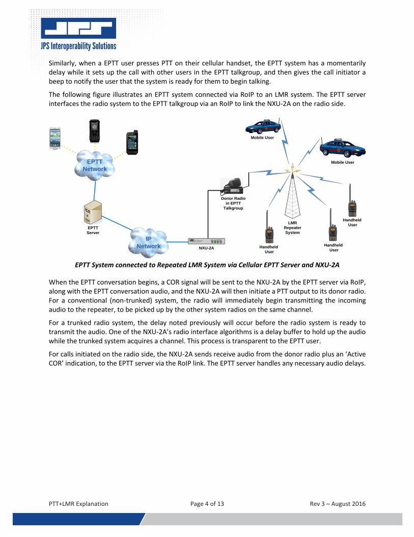
The following figure illustrates an EPTT system connected via RoIP to an LMR system. The EPTT server interfaces the radio system to the EPTT talkgroup via an RoIP to link the NXU-2A on the radio side.
Donor Radio
in EPTT
Talkgroup
EPTT
Network
LMR
Repeater
System
Mobile User
Handheld
User
IP
Network
EPTT
Server
Handheld
User
Handheld
User
Mobile User
NXU-2A
MAIN
POWER
LINK
ACTIVE
CHANNEL
ACTIVE
AUDIO
INPUTJPS Communications, Inc.
NXU-2 NETWORK EXTENSION UNIT
EPTT System connected to Repeated LMR System via Cellular EPTT Server and NXU-2A
When the EPTT conversation begins, a COR signal will be sent to the NXU-2A by the EPTT server via RoIP, along with the EPTT conversation audio, and the NXU-2A will then initiate a PTT output to its donor radio. For a conventional (non-trunked) system, the radio will immediately begin transmitting the incoming audio to the repeater, to be picked up by the other system radios on the same channel.
For a trunked radio system, the delay noted previously will occur before the radio system is ready to transmit the audio. One of the NXU-2A’s radio interface algorithms is a delay buffer to hold up the audio while the trunked system acquires a channel. This process is transparent to the EPTT user.
For calls initiated on the radio side, the NXU-2A sends receive audio from the donor radio plus an ‘Active COR’ indication, to the EPTT server via the RoIP link. The EPTT server handles any necessary audio delays.

PTT+LMR Explanation Page 5 of 13 Rev 3 – August 2016
There is no practical limitation on the number of radio channels or talkgroups that can be included in an EPTT talkgroup, though each will need its own dedicated NXU-2A/donor radio combination:
Donor Radio
on CH 1
Donor Radio
on CH 2
EPTT
Network
LMR
Repeater
System
Mobile User CH 1
Handheld
User CH 1
IP
Network
EPTT
Server
Handheld
User CH 1
Handheld
User CH 2
Mobile User CH 2
NXU-2ANXU-2A
MAIN
POWER
LINK
ACTIVE
CHANNEL
ACTIVE
AUDIO
INPUTJPS Communications, Inc.
NXU-2 NETWORK EXTENSION UNIT
MAIN
POWER
LINK
ACTIVE
CHANNEL
ACTIVE
AUDIO
INPUTJPS Communications, Inc.
NXU-2 NETWORK EXTENSION UNIT
Multiple Radio Channels Connected via NXU-2A devices)
While the radios shown above are in the same LMR Repeater system, they could be in entirely other systems in widely spaced locations. A benefit of JPS’ RoIP technology is that system radios can be located anywhere there is a network connection.
Use of JPS ACU Radio Interoperability Gateways as Radio to RoIP Interfaces for EPTT+LMR
JPS Interoperability Solutions also offers a variety of Radio Interoperability Gateways. Their main purpose is to capably link any voice communications format to any other. Because these gateways feature both radio and RoIP interfaces (along with interfaces for a variety of other voice communications formats) they can function as multiple-channel versions of the NXU-2A in EPTT+LMR applications.
The gateway most suited is the ACU-2000; its merits are described in the following section.
EPTT to LMR integration using the JPS ACU-2000 Modular Radio Interoperability Gateway
The ACU-2000 is capable of linking donor resources locally as well as over an IP network. A typical setup includes the following: local cross-connections within the chassis controlled by the CPM module, an HSP module providing local control and monitoring, and up to 12 interface modules installed as needed to link devices such as radios, cell phones, telephones, SIP phones, iDEN phones, or satellite phones to the system. This “Local Interoperability System” can be interfaced via an IP network with software control programs, remote radios, SIP devices, and other Local Interoperability Systems.
The ACU-2000 can provide up to twelve EPTT+LMR channels. Each DSP-2 module is capable of a single RoIP-to-Radio link, just like a single NXU-2A device.

PTT+LMR Explanation Page 6 of 13 Rev 3 – August 2016
ACU-2000 Twelve Channel Interoperability Gateway
A stripped-down version, minus the CPM and HSP modules, is the most cost-effective EPTT+LMR solution, including only the modules necessary: A PSM-1A power supply module plus one DSP-2 module for each required EPTT+LMR link; from 4 to 12 links Note that this version does not have the capability of interoperability links between the DSP-2A modules in the chassis, but these are not needed if the system conferencing links are all done within EPTT.
This application is most useful for cases in which there are numerous donor radio resources at the same location, as illustrated below:
Donor Radio
on CH 1
Donor Radio
on CH 12
EPTT
Network
LMR
Repeater
System
Mobile User CH 1
Handheld
User CH 1
IP
Network
EPTT
Server
Handheld
User CH 1
Handheld
User CH 12
Mobile User CH 12
ACU-2000 Configured
with 12 DSP-2s
PTT
SIGNAL
ETHERNET
FAULT
01
DSP-2 IP
COR
LINK
ACTIVE
PTT
SIGNAL
ETHERNET
FAULT
02
DSP-2 IP
COR
LINK
ACTIVE
PTT
SIGNAL
ETHERNET
FAULT
03
DSP-2 IP
COR
LINK
ACTIVE
PTT
SIGNAL
ETHERNET
FAULT
04
DSP-2 IP
COR
LINK
ACTIVE
PTT
SIGNAL
ETHERNET
FAULT
05
DSP-2 IP
COR
LINK
ACTIVE
PTT
SIGNAL
ETHERNET
FAULT
06
DSP-2 IP
COR
LINK
ACTIVE
PTT
SIGNAL
ETHERNET
FAULT
07
DSP-2 IP
COR
LINK
ACTIVE
PTT
SIGNAL
ETHERNET
FAULT
08
DSP-2 IP
COR
LINK
ACTIVE
PTT
SIGNAL
ETHERNET
FAULT
09
DSP-2 IP
COR
LINK
ACTIVE
ACU-2000
+12 V
-12 V
POWER
AC
DC
PSM-1 IP
PTT
SIGNAL
ETHERNET
FAULT
10
DSP-2 IP
COR
LINK
ACTIVE
PTT
SIGNAL
ETHERNET
FAULT
11
DSP-2 IP
COR
LINK
ACTIVE
PTT
SIGNAL
ETHERNET
FAULT
12
DSP-2 IP
COR
LINK
ACTIVE
Cellular EPTT Server Interfacing to Multiple Donor Radios via ACU-2000
© 2016 JPS. All rights reserved. For more information about JPS products, visit www.jpsinterop.com
AT&T is a registered trademark of AT&T Intellectual Property and/or AT&T affiliated companies. For more information on AT&T EPTT, see www.att.com/eptt
.

PTT+LMR Explanation Page 7 of 13 Rev 3 – August 2016
Appendix A
EPTT Interoperability with Full Function JPS Gateways
Appendix A explains the capabilities and requirements for connecting an EPTT system to a complete JPS interoperability system, allowing potential for dynamic connectivity between EPTT talkgroups and any of the communications systems that are members of that JPS gateway. This contrasts with the one-to-one connections between a EPTT talkgroup and a single LMR channel or talkgroup previously described.
JPS has deployed over 8,800 ACU radio interoperability gateways in public safety, government, military and commercial environments around the world. The gateways create interoperability systems that range from small standalone local domains to large region-wide, state-wide, and nation-wide systems.
It is possible to connect an EPTT talkgroup (or talkgroups) to any of these existing gateways. Typically, no changes should be required, but an additional RoIP port may need to be added if none are available.
Refer to the diagram on the next page. This depicts an ACU-2000 with at least one of each type of ACU gateway interface module:
The Local Phone (LP) Module allows users to connect to the system with a standard telephone set. The phone’s DTMF keypad can be operated to make and break connections; alternatively, the LP user can be connected into an interoperability net by another authorized user or an operator employing the ACU Controller or WAIS Controller computer software.
The PSTN module provides an interface to a standard telephone line, allowing interoperability system users to dial out to external phone numbers or for (when enabled) outside users to dial in.
The diagram also shows multiple DSP modules interfacing radios (DSP A and DSP B) and an SCM module that interfaces VoIP users via the SIP protocol.
Most important for this discussion, however, is the remaining DSP module (DSP-C), which is interfacing the EPTT system via RoIP. This expands from the one-to-one EPTT talkgroup to radio channel model to an alternative model allows the EPTT talkgroup to interface all of the available resources of an entire interoperability system.
Interoperability system operators will have the ability, using the various available control methods, to dynamically connect the EPTT talkgroup into interoperability nets (voice communications conferences) that can include any or all of the other members of the system.
For existing gateways, all that is required is an available RoIP port on the gateway. DSP modules on ACU-2000 systems can be configured as RoIP ports. An existing module can be set up as the RoIP interface to the EPTT server, or another can be added for this purpose. ACU-M units have a pair of available RoIP ports, allowing one or two RoIP connections to the EPTT server.
Note that this version requires the CPM and HSP modules for interoperability between modules.

PTT+LMR Explanation Page 8 of 13 Rev 3 – August 2016
Various Voice Communication Devices Interfaced to an ACU-2000 Gateway

PTT+LMR Explanation Page 9 of 13 Rev 3 – August 2016
DSP Radio Interface Algorithms
The ACU-2000 and ACU-M gateways, as well as the NXU-2A, feature a suite of sophisticated DSP algorithms that resolve the many problems that can occur when radio systems are connected together or to other types of voice communications devices. These features are a major part of what separates JPS from other gateway providers. An important feature is the very capable VOX function that’s used to let the ACU know when someone is conversing on the EPTT talkgroup. VOX stands for “Voice Operated Xmit (transmit)” and when audio is detected coming from the donor handset by the VOX function, the connected donor radio is put into transmit mode and sends the EPTT talkgroup audio to other radios in the system. The VOX function includes various audio and timing delays. One of them ensures that the initial audio syllables are not lost. These are any syllables that are uttered while the VOX function is doing its job but has not quite yet determined that a valid signal is present. Another timer prevents the PTT function from being tripped repeatedly during minor pauses in speech.
Cable Assemblies for Donor Radios
JPS offers interface cables optimized for use with over 300 makes and models of LMR radios. Each has a circuit board with attenuation networks and coupling capacitors, set for optimal performance with the specific radio. New cables are added as new radio models are released and a requirement is stated.
All JPS interface cables have an associated Application Notes document, supplied with the cable and also available from JPS. The notes indicate proper, factory-optimized settings for the available radio interface configuration options. These are identical to the settings that are automatically set when the associated Radio Template is applied.
All cables, including any custom EPTT cables, are designed to conform to the gateway’s default settings wherever possible, minimizing setup adjustment requirements.
Radio Templates
The JPS ACU Gateways also have the ability to use radio templates that are created to correspond with each radio cable; when applied, they configure the gateway’s configuration settings to those optimized for best operation with that radio/radio cable. Keep in mind that these optimized settings may not be best for each individual radio, and some individual “tweaking” of settings may improve performance.

PTT+LMR Explanation Page 10 of 13 Rev 3 – August 2016
ACU Gateway Control Methodologies
ACU Gateways can be accessed and controlled in multiple ways. These include:
Via DTMF from landline or VoIP phones (when enabled),
Locally by the keypad of an ACU-2000 or ACU-T, or by using the ACU-M top control panel
Remotely using the ACU Controller or Wide Area Interoperability System (WAIS) Controller software programs
Most common is via one of the software programs. The ACU Controller handles an individual ACU gateway, and the WAIS Controller can monitor and control a wide-area system made up of multiple ACU Gateways and NXU devices dispersed over a wide area, such as a multi-county, statewide, or Federal system.
An ACU Controller screen is shown below. All modules that are not currently connected to others are depicted by icons on the top row. When any are pulled down into the Net lines they are engaged in an interoperability conference. The HSP module as well as DSP modules #1 and #2 are in an interoperability net. When the local operator keys the HSP handset, that operator’s speech is sent out over the two donor radios interfaced to the #1 and #2 DSP modules. As can be seen, this means active COR at the handset, which creates active PTT on the other members of the interoperability net.
DSP module #4 is in a net with the #11 module, set up as a RoIP interface. The is no COR or PTT activity because no one is currently talking. This could represent a radio at #4 and a EPTT talkgroup at # 11.
.
ACU Controller Software - Connections Screen

PTT+LMR Explanation Page 11 of 13 Rev 3 – August 2016
The WAIS Controller software controls and monitors systems made up of any number of ACU gateways and NXU devices. Its operators can monitor, communicate with, and link any number of system communications devices and systems via an IP network, using its intuitive Graphical User Interface shown in the figure below. The Overview screen manages connections among all or any subset of sites, and an operator can switch to the Local View when it’s advantageous to focus on a single site. The WAIS Controller monitors the system and its network connections, keeping operators apprised of real-time system status.
WAIS Controller Software – Overview Screen
Through IP connectivity, other authorized users can also access the WAIS system from other locations throughout the state. Operators have the ability to cross-connect assets at the local level as well as cross-connect assets from other WAIS-enabled Gateways. With WAIS Enterprise edition, system Operators become Dispatchers, able to use the sound cards of their PCs to communicate directly with associated radio systems. They who may also use the system to converse with each other over IP.
Note the Blue NXU icons for Bridge Patrol, WAIS Dispatch, and WAIS Operator. These show sites connected via individual NXU-2A devices. EPTT Talkgroups can be similarly included in a WAIS system via an RoIP connection to an NXU-2A device. They will also have full system connectivity capability if interfaced to a DSP module in any ACU gateway that is part of the Wide Area System.

PTT+LMR Explanation Page 12 of 13 Rev 3 – August 2016
Appendix B
Relevant Specifications NXU-2A and ACU-2000
NXU-2A Specifications
Physical dimensions 1.7” H x 7” W x 9” D (4.3 x 17.8 x 22.9cm)
Rack mountable No
Power requirements 12V DC Nominal, +11 to +15VDC @ 0.5A max; external supply provided
Number of ports Connects to one (1) analog voice communication device across an IP link
List of radio interfaces supported Interface cables (with DB-15 connector and NXU adapter) are available for over 300 radio makes/models; same cables as are used by ACU gateways. Current list available from JPS
IP Interface supported RoIP (JPS proprietary Radio over IP protocol)
Floor Control Mechanism A status byte in each packet includes a bit which identifies whether the sending unit is unsquelched (and therefore the receiving unit should transmit the audio)
Codecs supported
GSM 13Kbps - Suitable for voice communications only. Should not be used if any tone signaling is required. Offers the greatest compression with reasonable voice quality. This is the default setting. ADPCM 16Kbps – Suitable for voice or tone signaling. Offers good voice compression, but the voice quality is lower than the other compression methods. ADPCM 24Kbps – Suitable for voice or tone signaling. Offers less compression than ADPCM 16Kbps but the voice quality is higher. ADPCM 32Kbps – Suitable for voice or tone signaling. Offers still less compression, but the voice quality is the best of the ADPCM compression types. PCM 64Kbps – Suitable for voice or tone signaling. Offers the highest quality of all compression methods, but provides the least compression. You should use this method only if your network offers low latency and good throughput.
Sampling rate 8 KHz for all RoIP vocoders.
Security/VPN support N/A: The unit has no security beyond password protection. Security and VPN support are both dependent on the network devices used to route to the device.

PTT+LMR Explanation Page 13 of 13 Rev 3 – August 2016
ACU-2000 Specifications
Description The ACU-2000 is a modular gateway capable of interfacing to most types of voice communications devices. Various interface modules connect different types of devices to the unit. These interface modules include DSP (radio, other four wire devices), SCM (SIP phone, SIP PBX), PSTN (PSTN, cellular gateway), and LP (local telephone set). DSP-2 modules can also be provisioned in a “passthrough” mode so that these modules behave similarly to individual NXU-2A RoIP units.
Physical dimensions 5.25” H x 19” W x 11” D (13.3 x 48.3 x 28 cm)
Rack mountable Uses 3U of rack space, plus an additional 1U above and below for heat dissipation
Power requirements AC: 115/230 VAC ±15%, 47-63 Hz, 80 VA Typical, 100 VA Maximum DC: +11 to +15 VDC @ 4A Nominal
Number of ports Up to twelve modules van be installed to connects up to twelve audio devices
List of radio interfaces supported Interface cables are available for over 300 radio makes/models; same cables as other ACU gateways & NXU-2A – List Available from JPS
IP Interface supported RoIP (JPS proprietary Radio over IP protocol)
Floor Control Mechanism A status byte in RoIP each packet includes a bit which identifies whether the sending unit is unsquelched (and therefore the receiving unit should transmit the audio)
Codecs supported (ROIP)
GSM 13Kbps - Suitable for voice communications only. Should not be used if any tone signaling is required. Offers the greatest compression with reasonable voice quality. This is the default setting. ADPCM 16Kbps – Suitable for voice or tone signaling. Offers good voice compression, but the voice quality is lower than the other compression methods. ADPCM 24Kbps – Suitable for voice or tone signaling. Offers less compression than ADPCM 16Kbps but the voice quality is higher. ADPCM 32Kbps – Suitable for voice or tone signaling. Offers still less compression, but the voice quality is the best of the ADPCM compression types. PCM 64Kbps – Suitable for voice or tone signaling. Offers the highest quality of all compression methods, but provides the least compression. You should use this method only if your network offers low latency and good throughput.
Codecs supported (SIP) GSM, G711µ
Sampling rate 8 KHz for all RoIP vocoders.
Security/VPN support N/A: The unit has no security beyond password protection. Security and VPN support are both dependent on the network devices used to route to the device.