atraining program for shipyard personnel · paint film defects part b surface preparation: the key...
TRANSCRIPT
ATRAININGPROGRAMFORSHIPYARDPERSONNEL
NAMESHIPYARD
A project of the National Shipbuilding Research Program
U. S. Department of CommerceMaritime Administrationin cooperation withAvondale Shipyards, Inc.
Copyright 1979

Report Documentation Page Form ApprovedOMB No. 0704-0188
Public reporting burden for the collection of information is estimated to average 1 hour per response, including the time for reviewing instructions, searching existing data sources, gathering andmaintaining the data needed, and completing and reviewing the collection of information. Send comments regarding this burden estimate or any other aspect of this collection of information,including suggestions for reducing this burden, to Washington Headquarters Services, Directorate for Information Operations and Reports, 1215 Jefferson Davis Highway, Suite 1204, ArlingtonVA 22202-4302. Respondents should be aware that notwithstanding any other provision of law, no person shall be subject to a penalty for failing to comply with a collection of information if itdoes not display a currently valid OMB control number.
1. REPORT DATE 1979
2. REPORT TYPE N/A
3. DATES COVERED -
4. TITLE AND SUBTITLE Paint and Surface Preparation A Training Program for Shipyard Personnel
5a. CONTRACT NUMBER
5b. GRANT NUMBER
5c. PROGRAM ELEMENT NUMBER
6. AUTHOR(S) 5d. PROJECT NUMBER
5e. TASK NUMBER
5f. WORK UNIT NUMBER
7. PERFORMING ORGANIZATION NAME(S) AND ADDRESS(ES) Naval Surface Warfare Center CD Code 2230 - Design Integration ToolsBuilding 192 Room 128-9500 MacArthur Blvd Betheda, MD 20817-5700
8. PERFORMING ORGANIZATIONREPORT NUMBER
9. SPONSORING/MONITORING AGENCY NAME(S) AND ADDRESS(ES) 10. SPONSOR/MONITOR’S ACRONYM(S)
11. SPONSOR/MONITOR’S REPORT NUMBER(S)
12. DISTRIBUTION/AVAILABILITY STATEMENT Approved for public release, distribution unlimited
13. SUPPLEMENTARY NOTES
14. ABSTRACT
15. SUBJECT TERMS
16. SECURITY CLASSIFICATION OF: 17. LIMITATION OF ABSTRACT
SAR
18. NUMBEROF PAGES
106
19a. NAME OFRESPONSIBLE PERSON
a. REPORT unclassified
b. ABSTRACT unclassified
c. THIS PAGE unclassified
Standard Form 298 (Rev. 8-98) Prescribed by ANSI Std Z39-18

FOREWORD
Paint and surface preparation have become increasingly importantto the American shipbuilding industry. Paint department costs are nowthe third largest item in new ship construction. Costs have increasedand coating technology has become very complex. New equipment, materials,techniques of surface preparation and paint application have becomehighly specialized. In addition, drydocking times have increasedand surface treatments are expected to last longer. Developments andimprovements in this industry have an effect on production andmaintenance costs, which in turn have an effect on existing and futurejobs. The American shipbuilding industry must keep up with improvementsoverseas and remain competitive by reducing waste and keeping costs down.
Because of this, the U.S. Government has developed this trainingprogram to help you in learning and upgrading your knowledge and skillsin surface preparation, paint handling, and paint application making upthe total painting/coating job. Because there is a lot of informationto learn and remember in order to do an effective job, this workbook isdesigned to help you review operations you are already familiar withand learn new techniques and practices before you have to put them intoaction. The objectives are to make the training consistent, to simplifyyour job and to make it safer. The material is presented in a logicalorder with step by step instructions and illustrations. As an aid tolearning, you can refer back to various procedures for reinforcementof new information. A lot of space was left for you to make you ownnotes during training. This is your book - use it well.
The project was carried out under the National Shipbuilding ResearchProgram, in cooperation with Avondale Shipyards, Inc., Mr. John W. Peart,Program Manager. Development work was accomplished under subcontract tothe Lincoln Hall/Institute of Applied Technology, Mr. Jay I. Leanse,Executive Director, and Ms. Jess Gersky and Allyn Stanton, projectdirectors.
The authors wish to express their appreciation to the many individuals andcompanies who contributed their time and practical knowledge in thedevelopment of this training program. We wish to acknowledge the adviceand technical support of the SNAME 023-1 Committee, Mr. C. J. Starkenburg,Chairman, and Mr. Jack Garvey and Mr. Robert Schaffran of the MaritimeAdministration and those individuals who reviewed and connnented on the textin its draft form: Mr. Dean M. Berger, Gilbert/Commonwealth Associates;Mr. David Bloodgood, Bethlehem Steel Corporation; Mr. Walter Dany, BinksManufacturing Company; Mr. Benjamin S. Fultz, Offshore Power Systems, Inc;Mr. Daniel Krogh, Clemco Industries; Mr. Walter H. Radut, Exxon InternationalCompany; Mr. Frank H. Rack, Shipbuilding Consultants, Inc; and Mr. WalterMacDonald, FMC Corporation, Marine and Rail Equipment Division.

TABLE OF CONTENTS
PART AMarine Coating Technology: Insuring the Proper Protection . . . .
Unit I: Controlling Corrosion
Unit II: Properties ofShipyard Paints
Unit III: Achieving the MaximumPaint Service Life
Unit IV: Failure Resulting fromPaint Film Defects
PART BSurface Preparation: The Key to Coating Performance . . . .
Unit I: The Importance of SurfacePreparation
Unit II: How to Choose the Proper Methodfor Surface Preparation
Unit III: Equipment Set-Up for NozzleBlasting Efficiency
Unit IV: Efficient and Safe Practicesfor Surface Preparation
PART CPaint Application: Techniques and Practices . . . .
7
8
13
25
33
34
38
45
53
65
Unit I:
Unit II:
Unit III:
Unit IV:
Unit V:
Glossary
Getting Ready to Paint 66
Common Methods of ShipyardPaint Application 7 3
Set-Up and Efficient Operationof Spray Equipment 77
Good Spraying Practices 89
Safety and Health Measures inPaint Application 97
102


MARINECOATINGTECHNOLOGY
UNIT IIPROPERTIES OF SHIPYARD PAINTS
UNIT IllACHIEVING THE MAXIMUMPAINT SERVICE LIFE
UNIT IVFAILURE RESULTING FROMPAINT FILM DEFECTS7
PART A UNIT I
CONTROLLING CORROSION
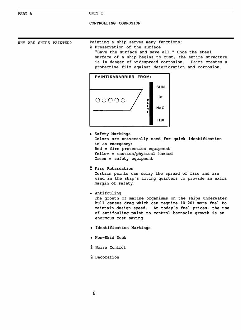
WHY ARE SHIPS PAINTED? Painting a ship serves many functions:Ž Preservation of the surface
“Save the surface and save all." Once the steelsurface of a ship begins to rust, the entire structureis in danger of widespread corrosion. Paint creates aprotective film against deterioration and corrosion.
PAINTISABARRIER FROM:
SUN
O2
NaCI
H20
• Safety MarkingsColors are universally used for quick identificationin an emergency:Red = fire protection equipmentYellow = caution/physical hazardGreen = safety equipment
Ž Fire RetardationCertain paints can delay the spread of fire and areused in the ship’s living quarters to provide an extramargin of safety.
• AntifoulingThe growth of marine organisms on the ships underwaterhull causes drag which can require 10-20% more fuel tomaintain design speed. At today’s fuel prices, the useof antifouling paint to control barnacle growth is anenormous cost saving.
• Identification Markings
• Non-Skid Deck
Ž Noise Control
Ž Decoration
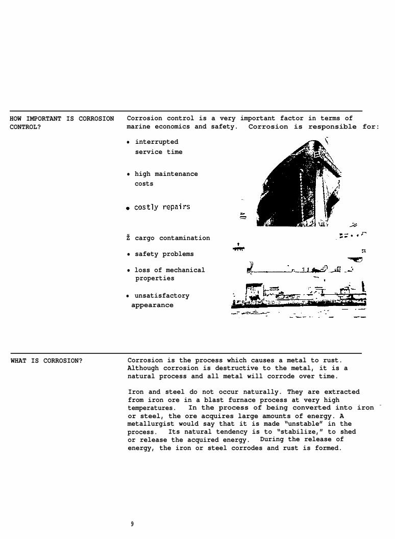
HOW IMPORTANT IS CORROSION Corrosion control is a very important factor in terms ofCONTROL? marine economics and safety. Corrosion is responsible for:
• interruptedservice time
• high maintenancecosts
Ž cargo contamination
• safety problems
• loss of mechanicalproperties
• unsatisfactoryappearance
WHAT IS CORROSION? Corrosion is the process which causes a metal to rust.Although corrosion is destructive to the metal, it is anatural process and all metal will corrode over time.
Iron and steel do not occur naturally. They are extractedfrom iron ore in a blast furnace process at very hightemperatures. In the process of being converted into iron –
or steel, the ore acquires large amounts of energy. Ametallurgist would say that it is made “unstable” in theprocess. Its natural tendency is to “stabilize,” to shedor release the acquired energy. During the release ofenergy, the iron or steel corrodes and rust is formed.
9
Chemically, rust is the same as iron ore. Both are made ofiron and oxygen; both are iron oxide. The process ofcorrosion can therefore be viewed as a cycle of nature.
NATURAL CYCLE OF CORROSION
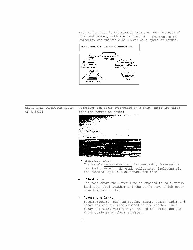
WHERE DOES CORROSION OCCUR Corrosion can occur everywhere on a ship. There are threeON A SHIP? distinct corrosion zones:
• Immersion Zone.The ship’s underwater hull is constantly immersed insea (salt) water. Man-made pollutants, including oiland chemical spills also attack the steel.
The zone above the water line is exposed to salt spray,humidity, foul weather and the sun’s rays which breakdown the paint film.
Superstructure, such as stacks, masts, spars, radar andsonar devices are also exposed to the weather, saltspray and ultra violet rays, and to the fumes and gaswhich condense on their surfaces.
10
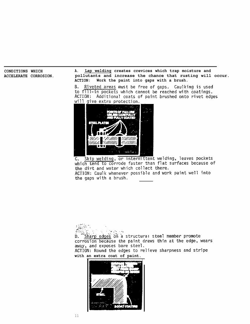
CONDITIONS WHICH A. Lap welding creates crevices which trap moisture andACCELERATE CORROSION. pollutants and increase the chance that rusting will occur.
ACTION: Work the paint into gaps with a brush.
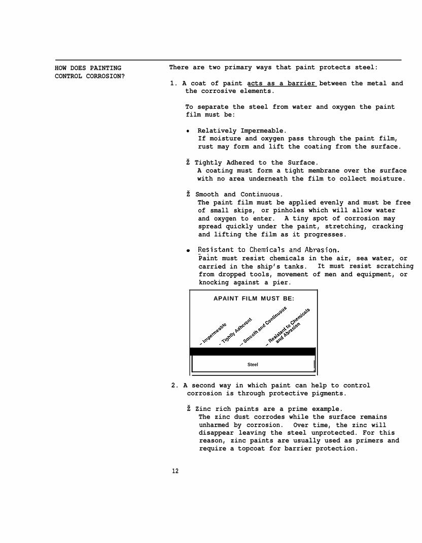
with an extra coat of paint.
11
HOW DOES PAINTING There are two primary ways that paint protects steel:CONTROL CORROSION?
1. A coat of paint acts as a barrier between the metal andthe corrosive elements.
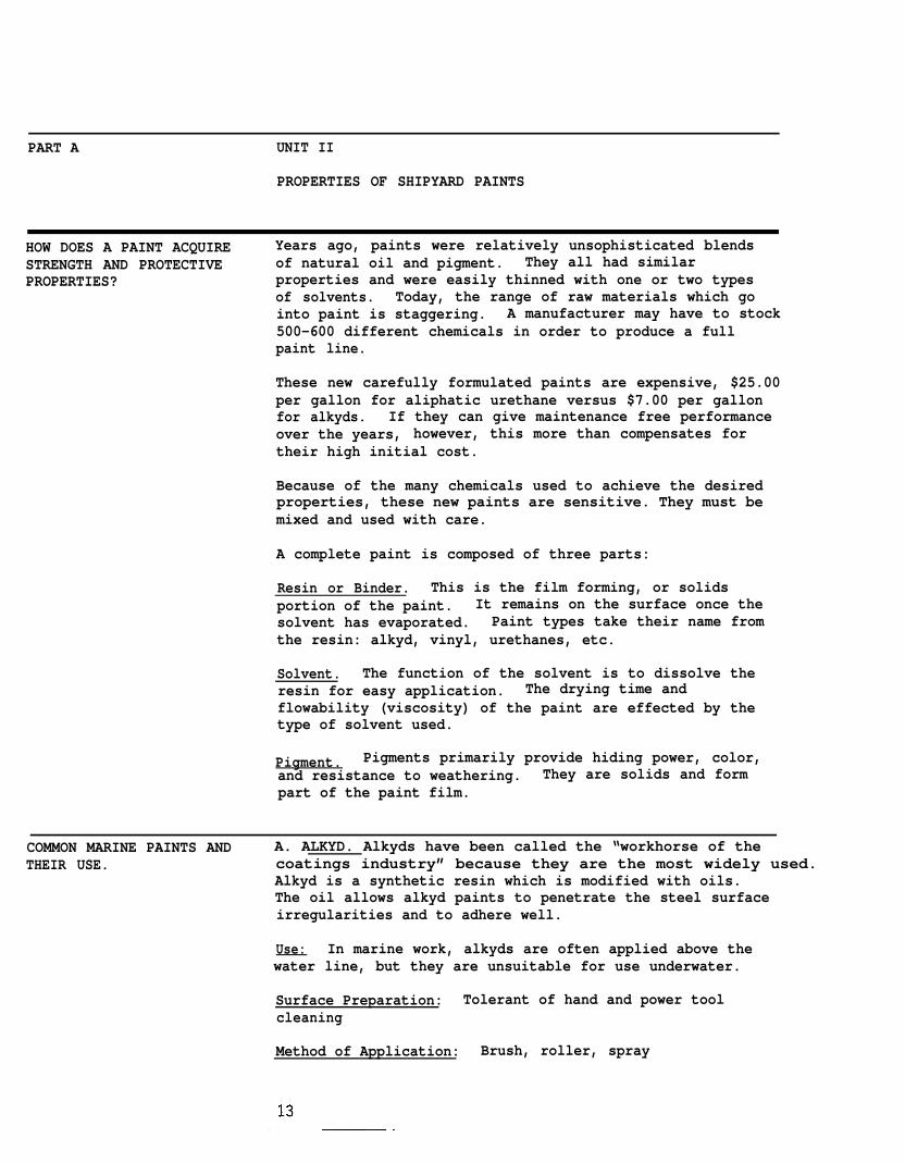
To separate the steel from water and oxygen the paintfilm must be:
• Relatively Impermeable.If moisture and oxygen pass through the paint film,rust may form and lift the coating from the surface.
Ž Tightly Adhered to the Surface.A coating must form a tight membrane over the surfacewith no area underneath the film to collect moisture.
Ž Smooth and Continuous.The paint film must be applied evenly and must be freeof small skips, or pinholes which will allow waterand oxygen to enter. A tiny spot of corrosion mayspread quickly under the paint, stretching, crackingand lifting the film as it progresses.
Paint must resist chemicals in the air, sea water, orcarried in the ship’s tanks. It must resist scratchingfrom dropped tools, movement of men and equipment, orknocking against a pier.
APAINT FILM MUST BE:
Steel !2. A second way in which paint can help to control
corrosion is through protective pigments.
Ž Zinc rich paints are a prime example.The zinc dust corrodes while the surface remainsunharmed by corrosion. Over time, the zinc willdisappear leaving the steel unprotected. For thisreason, zinc paints are usually used as primers andrequire a topcoat for barrier protection.
12
PART A UNIT II
PROPERTIES OF SHIPYARD PAINTS
HOW DOES A PAINT ACQUIRE Years ago, paints were relatively unsophisticated blendsSTRENGTH AND PROTECTIVE of natural oil and pigment. They all had similarPROPERTIES? properties and were easily thinned with one or two types
of solvents. Today, the range of raw materials which gointo paint is staggering. A manufacturer may have to stock500-600 different chemicals in order to produce a fullpaint line.
These new carefully formulated paints are expensive, $25.00per gallon for aliphatic urethane versus $7.00 per gallonfor alkyds. If they can give maintenance free performanceover the years, however, this more than compensates fortheir high initial cost.
Because of the many chemicals used to achieve the desiredproperties, these new paints are sensitive. They must bemixed and used with care.
A complete paint is composed of three parts:
Resin or Binder. This is the film forming, or solidsportion of the paint. It remains on the surface once thesolvent has evaporated. Paint types take their name fromthe resin: alkyd, vinyl, urethanes, etc.
Solvent. The function of the solvent is to dissolve theresin for easy application. The drying time andflowability (viscosity) of the paint are effected by thetype of solvent used.
Pigment. Pigments primarily provide hiding power, color,and resistance to weathering. They are solids and formpart of the paint film.
COMMON MARINE PAINTS AND A. ALKYD. Alkyds have been called the “workhorse of theTHEIR USE. coatings industry” because they are the most widely used.
Alkyd is a synthetic resin which is modified with oils.The oil allows alkyd paints to penetrate the steel surfaceirregularities and to adhere well.
Use: In marine work, alkyds are often applied above thewater line, but they are unsuitable for use underwater.
Surface Preparation: Tolerant of hand and power toolcleaning
Method of Application: Brush, roller, spray
Solvents: Mineral Spirits, VM&P Naphtha, Xylol
Other Characteristics: Easy to apply; moderate gloss andcolor retention; may be applied to relatively lowtemperatures.
B. BITUMINOUS. Bituminous coatings -- asphaltic andcoal tar pitch materials -- are widely used in highlycorrosive atmospheres and where the black color is not aproblem. Coal tar pitch is superior to asphalt as awater barrier, but it gets brittle when exposed to air,heat, and sunlight.
Use: On shipbottoms where impermeability is important,Bituminous coatings are often used. They are also appliedas anticorrosive paints in ballast tanks and chain-lockers.
Surface Preparation: Commercial blast for immersionservice. For recoating, fresh water wash, scraping, andpower tool cleaning of bad areas is acceptable.
Method of Application: Brush, roller, spray
Solvents: Aromatics, Mineral Spirits
Other Characteristics: May be applied on top of most otherpaints without risk of lifting undercoats; easy to recoat;good wetting properties.
C. CHLORINATED RUBBER. Chlorinated Rubber is made byexposing natural rubber to chlorine gas. The resin whichresults is outstanding in its resistance to water andcommon corrosive chemicals. It is a good water vaporbarrier and resists strong acids, alkalis, mineral oils,mold and mildew. It is odorless, tasteless, non-toxicand non-flammable.
Use: Chlorinated Rubber may be recommended for allexterior ship areas: bottom, boottop, weather deck andsuperstructure. It is relatively quick drying -- it maybe dry to touch in 30 minutes. Full cure usually requires4-8 hours.
Surface Preparation: Power tool cleaning or spot blastingfor recoating; near-white blast is recommended forimmersion service.
Method of Application: Spray, brush

Solvents: Xylene, Toluene
Other Characteristics: Easy to recoat, good gloss, andcolor retention; applicable at low temperatures; low filmbuild per coat.
D. EPOXY. Epoxy resin is found in a large group of epoxycoatings which are widely used in shipyards because theyhave a combination of many desirable properties: excellentadhesion, durability, and chemical resistance. Epoxiesare two-package, or catalyzed, paints. The three types ofcatalysts are: polyamine, amine adduct, and polyamide.Coal-tar epoxy is a blend of coal-tar pitch and epoxy resin.
Use: Amine cured, polyamide cured, and coal-tar epoxiesare used on shipbottoms. Epoxy polyamide may also bespecified for boottop, weather deck, superstructure areas,and on the inside of oil, water, and chemical tanks.
Surface Preparation: White metal blast for immersionservice; a near-white blast is required for good adhesionin new construction. In M & R, spot blasting or powertool cleaning is acceptable.
Method of Application: Spray, brush
Solvents: MEK, MIBK, Xylene, Toluence
Other Characteristics: Good chemical and oil resistance;some epoxies may be applied under water; hard and slickfilm with excellent adhesion.
E. INORGANIC ZINC. Inorganic zinc-rich coatings consistof at least 80% zinc dust which is dispersed in the vehicleportion. Zinc dust has very good hiding power. It is usedto inhibit corrosion, serving as a sacrificial material-- the steel is protected at the expense of the zinc.
Use: Inorganic Zinc is used on weather decks, thesuperstructure, and on off-shore structures.
Surface Preparation: Near-white or white metal blast isrequired
Method of Application: Spray application only
Other Characteristics: High resistance to heat; provides“galvanic” protection to metals; constant stirringnecessary to keep the zinc dust evenly dispersed.
15
F. POLYURETHANE. This is one of the newest man-maderesins used in coatings today. Polyurethane resin is usedin a wide range of coatings,- from hard glossy enamels tosoft flexible coatings and insulating foams.
Use: Polyurethane coatings are suitable for use on tanksand in the boottop, topside, weather deck andsuperstructure areas.
Surface Preparation: Near-white blast is recommended fornew construction; power tool cleaning is acceptable forrecoating
Method of Application: Spray, brush
Solvents: Ethyl or Butyl Acetate, MEK, MIBK
Other Characteristics: Polyurethane can be applied atlow temperatures, have excellent gloss retention and arehighly resistant to chemicals and solvents. They may bedifficult to apply and may produce strong toxic reactionsin some painters.
G. VINYL. Vinyl coatings are widely used. They haveexcellent durability and resistance to acids, alkalis,chemicals and seawater, and they will not supportcombustion.
Use: Vinyls are commonly used in coating marineeqipment. When coal-tar pitch is added to vinyl (vinylcoal-tar), additional underwater protection is providedfor a shipbottom. Vinyl acrylics may be applied to theboottop, weather deck,- and superstructure areas.
Surface Preparation: Near-white blast is recommendednew work
Method of Application: Spray is recommended
Solvents: MEK, MIBK
for
Other Characteristics: A prime coat is usually required;may be applied at low temperatures; qloss retention isimfiroved” with the addition of acrylic resins.
H. ANTI-FOULING. Anti-fouling paints are used onshipbottoms to inhibit the attachment of barnacles, grass,algae and other marine growths. Cuprous oxide, a biotoxin,is the major anti-fouling ingredient in the various
16
coatings which are used on shipbottoms -- bituminous,vinyl, vinyl pitch, epoxy, coal-tar epoxy, chlorinatedrubber and flake glass. Organotin compounds are also usedas toxic substances. Cuprous oxide provides exceptionalresistance to shell fouling; resistance to the growth ofweeds and grasses is boosted when organotins are added.
17
PART A UNIT III
ACHIEVING THE MAXIMUM PAINT SERVICE LIFE
HOW TO READ A High performance paints require special handling toMANUFACTURER’S DATA SHEET achieve the excellent performance promised by the
manufacturers. The painter, therefore, must befamiliar with each product’s characteristics, specialproperties, and mixing and application requirements.
The manufacturer’s data sheet, or product data sheet,contains information essential for equality applicationand safe use. Studying it before beginning the job willreduce paint failures and the need for rework.
Refer to the sample data sheet while reviewing thefollowing terms and instructions.
I & II-Description of the Paint
This section provides basic information on paint type andareas of recommended use. If there is conflict betweenthis data and what is called out in the specification,contact the technical representative for advice.
III-Physical Properties
% Volume Solids. Paint contains solids which form the dryfilm and solvents which are needed to make the materialliquid during application. In order for the operatorto set his speed and stroke, he must be able tocalculate the expected dry film thickness (DFT) basedupon his wet film (WFT) measurements. The relationshipbetween DFT and WFT depends upon the paint’s percent ofsolids by volume.
Viscosity. Viscosity describes a paint’s consistency, howfast or slow it flows. Viscosity is specified as thelength of time it takes for the paint to flow through astandard measuring cup at a certain temperature. Properviscosity is important for good film build and ease ofapplication.
Number of Components. The data sheet specifies whether thecoating comes In one package, or two packages which must bemixed together. Be certain to have the proper number ofcontainers at the job site.
Flash Point. The flash point of a paint is the lowesttemperature at which the solvent releases enough vapor toignite in the presence of a flame. This temperature isindicated in degrees Fahrenheit. The higher thetemperature, the safer the paint is to use near an open

flame. In some two-package paints, the flash point isdifferent for each component.
Shelf Life. Shelf life is the length of time in which apaint may be stored at a given temperature and remain inusable condition. Cooler temperatures will increase theshelf life, whereas higher temperatures will severelyshorten it. Minimum and maximum storage temperatures arealso stated.
IV-Surface Preparation
To achieve good paint bonding, the surface must beproperly prepared. This includes cleanliness as wellas surface profile (see Part B, Unit I). The specificstandards which must be met are indicated. Specialinstructions for primer and touch-up applications are
I
also given by the manufacturer.
V-Mixing Procedure
For one-package paints, the data sheet will specitvue and amount of thinner to be used. Too much
fy theor theionsthinned
at all. They achieve their proper flowability by stirring.Follow directions closely.
For two-package paints, the data sheet will indicate theratio of catalyst to base such as 1 part catalyst to 4parts coating material. If the catalyst is pre-measured, that will be specified. Ratio information is essentialfor proper application and curing. The directions mustbe followed exactly.
The data sheet may also include instructions on mixingtechnique, when to add the catalyst, and how long to letthe coating “sweat in” before application (induction time).
The term “ pot life” applies to catalyzed two-packagepaints. It is the length of time in which the paint can beused once the components have been mixed together. Itchanges at different temperatures. Since the chemicalreaction starts as soon as the two packages have beenmixed, avoid mixing paint too long before it will be used.Paint that is allowed to stand beyond its pot life willcure in the container to a hard mass which cannot besprayed.
19

VI-Application Procedure
The product data sheet will give the recommendedapplication methods and required equipment. Oftendetailed information is given regarding the adjustmentof spray equipment. A thorough data sheet will includethe type of spray gun, the size of the fluid tip and aircap, ID of the material hose, and the pump pressurerecommended for good results.
Environmental Limitations. Air temperature, surfacetemperature and humidity affect paint application andcuring. The manufacturer will set limits for hisproduct.
Dry Time. Dry times are expressed in hours at a certaintemperature and humidity. Depending upon whatoperation is to follow the paint job, dry times may beexpressed as:
1. dry-to-recoat time or intercoat dry time: the timeelapsed before a second coat of paint may be applied.
2. dry-to-handle, the time elapsed before a surface orpiece of equipment or modular unit may be touched ormoved without damage to the coating, and
3. dry-for-immersion, drying time sufficient to allow forcomplete immersion such as floating a ship or fillinga tank.
WHY IS CURING TIME CRITICAL Curing time is critical at two points in paint application:TO A PAINT’S SERVICE LIFE?
Intercoat Curing. If the undercoat is allowed to cure toolong, the topcoat will not adhere. The underfilm will behard and smooth, leaving nothing for the topcoat to bitinto.
If the undercoat is not sufficiently cured, blisters andlifting may occur as trapped solvents in the uncuredundercoat try to escape.
Final Curing. Final cure must be obtained to achieve goodbonding and full expression of the paint’s protectivequalities.
20

WHAT IS THE DIFFERENCE While these terms are often used interchangeable, they doBETWEEN “CURED” AND not mean the same thing.“DRIED”?
A dry film is one which is “dry to touch”. When the thumbis pressed with moderate pressure on a dry film androtated 90 degrees, the paint film will not sag, streak,or hold a thumbprint.)
A coating may be dry to touch but may not be cured. Onlythe surface has dried and the hard “skin” may havetrapped solvents which can cause blistering. A curedcoating is dry thoughout and ready to perform itsintended function.
DRIED#CURED
WHY IS FILM THICKNESS The thickness of the dried paint film is set by theIMPORTANT? manufacturer to provide the maximum protection to the
surface.
If a film is too thin, it may:
Ž allow moisture to reach the metalŽ expose high points in the surface profile causing
pinpoint rushing
If a film is too thick, it may:
peel away from the surfacemud-crack (especially zinc-rich paints)cure improperly (because it cannot dry internally)and blister or peel
21
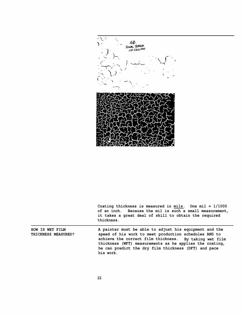
Coating thickness is measured in mils. One mil = 1/1000of an inch. Because the mil is such a small measurement,it takes a great deal of skill to obtain the requiredthickness.
HOW IS WET FILM A painter must be able to adjust his equipment and theTHICKNESS MEASURED? speed of his work to meet production schedules AND to
achieve the correct film thickness. By taking wet filmthickness (WFT) measurements as he applies the coating,he can predict the dry film thickness (DFT) and pacehis work.
22
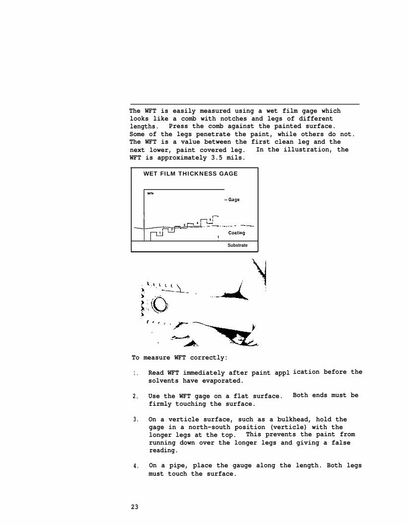
The WFT is easily measured using a wet film gage whichlooks like a comb with notches and legs of differentlengths. Press the comb against the painted surface.Some of the legs penetrate the paint, while others do not.The WFT is a value between the first clean leg and thenext lower, paint covered leg. In the illustration, theWFT is approximately 3.5 mils.
WET FILM THICKNESS GAGE
Substrate
To measure WFT correctly:
1.
2.
3.
4.
Read WFT immediately after paint applsolvents have evaporated.
Use the WFT gage on a flat surface.firmly touching the surface.
ication before the
Both ends must be
On a verticle surface, such as a bulkhead, hold thegage in a north-south position (verticle) with thelonger legs at the top. This prevents the paint fromrunning down over the longer legs and giving a falsereading.
On a pipe, place the gauge along the length. Both legsmust touch the surface.
23
5. Lift the guage from the surface without slidingSlipping or sliding will give a false reading, extrapaint will be picked up on the legs.
6. Use only a clean, dry gauge. Clean the gauge after eachreading. Dirt on the bottoms of the legs adds totheir length and gives lower readings.
HOW IS DRY FILM THICKNESS To calculate the expected DFT, you must have two pieces ofCALCULATED? information:
1. the measured WFT, and
2. the percentage of volume solids, as given in thesupplier’s data sheet.
To find the expected DFT, multiply the WFT by thepercentage of volum solids. The formula is:DFT = WFT X % volume solids.
Example. What is the DFT if a paint with 50% solids byvolume is sprayed to a wet film thickness of 4 roils?
Step 1. WFT X % volume solids = DFT4 mils X 50%= DFT
Step 2. Convert the percent to a decimal:50% ÷ 100= .50
Step 3. 4 mils X .50 = 2mils DFT
In this example, the DFT is one-half of the WFT. Half ofthe paint was made of solvents which evaporated, leavinga dry film with half the thickness of the wet film.
24
PART A UNIT IV
FAILURE RESULTING FROM PAINT FILM DEFECTS
CAN PAINT FAILURE BE All paints and coatings eventually deterioratePREVENTED? naturally. After several years of exposure to rain,
sun, and weathering, even the best paints begin to fade,crack or peel. However, early costly paint failure canbe prevented and the service life of a ship’s coatingcan be extended, if attention is paid to:
. proper surface preparation● proper paint selection● proper paint mixing● proper paint application. compatibility of paints
The more sophisticated the paint, the more important thesefactors become,
IDENTIFYING PAINT FILM Defects in the paint film can appear immediately after aDEFECTS coating is applied, after curing, or after months or years
of a ship’s service. Film defects can lead tocatastrophic paint failures and must be remedied before thesurface is damaged.
Cratering, Pitting.
Apperance: Small uniform indentations in the film.
Cause: Air pockets trapped in wet film during application.
Remedy: Sand or blast to a smooth finish. Applyadditional coats over the affected area.
Pinholing.
Appearance: A tiny but deep hole in the film where thesteel or a preceding coat of paint is exposed. Pinholeson the primer can be detected with a special electric- .currentunaided
Cause:settled
Remedy:
instrument. They are too small to be seen with theeye, but show up under 5-power magnification.
Insufficient paint atomized; coarse atomization;pigment.
Brush pinhole areas and apply an additional coatof paint.
25
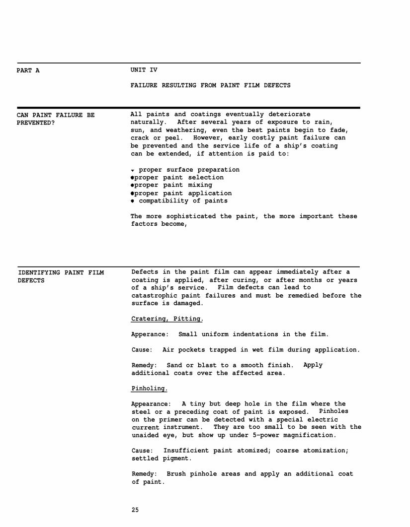
Fish Eyes.
Appearance: Separation or pulling apart of the wet film.Previous finish or substrate can be seen in spots.
Cause: Improper surface cleaning; spraying over oil, dirt,silicone; incompatible coatings.
Remedy: Blast or sand, followed by a brush coat. Sprayan additonal coat over the area.
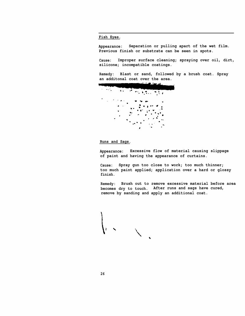
Runs and Sags.
Appearance: Excessive flow of material causing slippageof paint and having the appearance of curtains.
Cause: Spray gun too close to work; too much thinner;too much paint applied; application over a hard or glossyfinish.
Remedy: Brush out to remove excessive material before areabecomes dry to touch. After runs and sags have cured,remove by sanding and apply an additional coat.
26
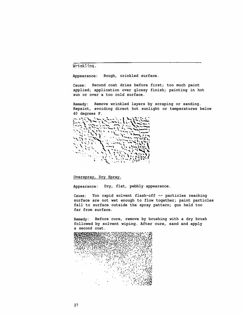
Appearance: Rough, crinkled surface.
Cause: Second coat dries before first; too much paintapplied; application over glossy finish; painting in hotsun or over a too cold surface.
Remedy: Remove wrinkled layers by scraping or sanding.Repaint, avoiding direct hot sunlight or temperatures below40 degrees F.
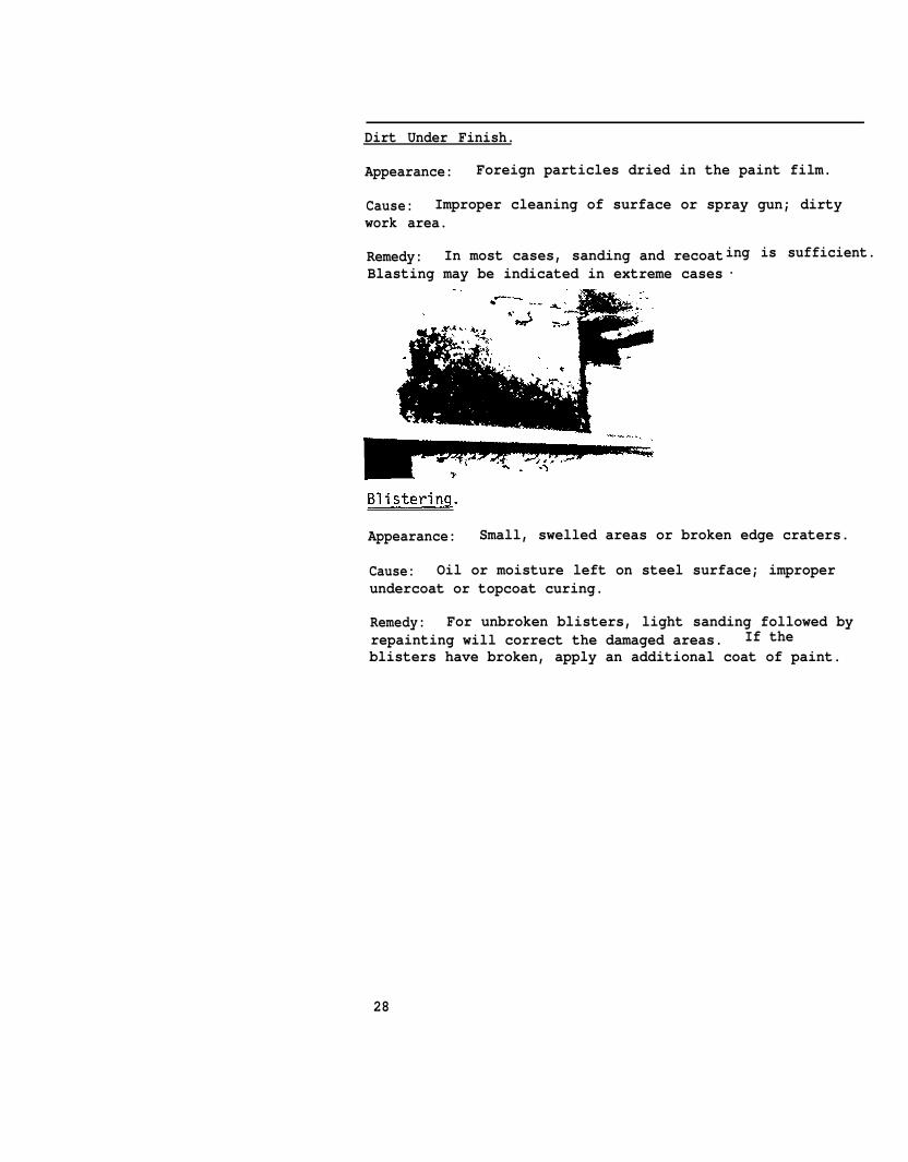
Overspray, Dry Spray.
Appearance: Dry, flat, pebbly appearance.
Cause: Too rapid solvent flash-off -- particles reachingsurface are not wet enough to flow together; paint particlesfall to surface outside the spray pattern; gun held toofar from surface.
Remedy: Before cure, remove by brushing with a dry brushfollowed by solvent wiping. After cure, sand and applya second coat.
27
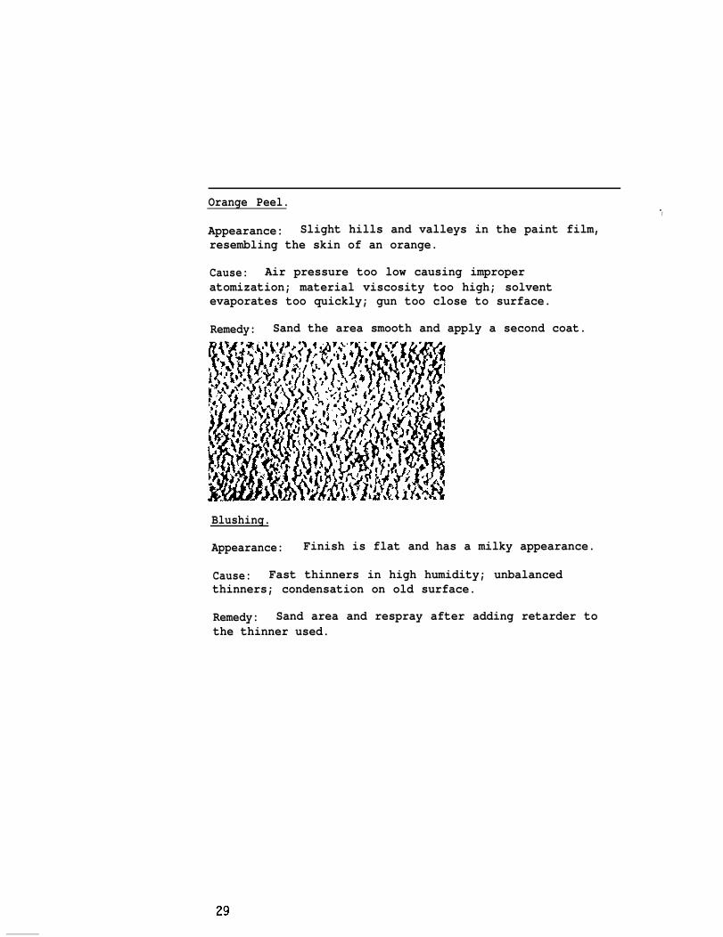
Dirt Under Finish.
Appearance: Foreign particles dried in the paint film.
Cause: Improper cleaning of surface or spray gun; dirtywork area.
Remedy: In most cases, sanding and recoatBlasting may be indicated in extreme cases
ing is sufficient..
Appearance: Small, swelled areas or broken edge craters.
Cause: Oil or moisture left on steel surface; improperundercoat or topcoat curing.
Remedy: For unbroken blisters, light sanding followed byrepainting will correct the damaged areas. If theblisters have broken, apply an additional coat of paint.
28
-,
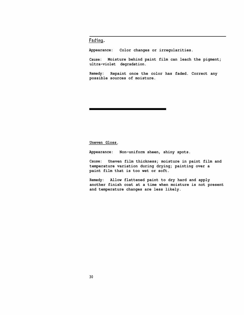
Orange Peel.Appearance: Slight hills and valleys in the paint film,resembling the skin of an orange.
Cause: Air pressure too low causing improperatomization; material viscosity too high; solventevaporates too quickly; gun too close to surface.
Remedy: Sand the area smooth and apply a second coat.
Blushing.
Appearance: Finish is flat and has a milky appearance.
Cause: Fast thinners in high humidity; unbalancedthinners; condensation on old surface.
Remedy: Sand area and respray after adding retarder tothe thinner used.
Appearance: Color changes or irregularities.
Cause: Moisture behind paint film can leach the pigment;ultra-violet degradation.
Remedy: Repaint once the color has faded. Correct anypossible sources of moisture.
Uneven Gloss.
Appearance: Non-uniform sheen, shiny spots.
Cause: Uneven film thickness; moisture in paint film andtemperature variation during drying; painting over apaint film that is too wet or soft.
Remedy: Allow flattened paint to dry hard and applyanother finish coat at a time when moisture is not presentand temperature changes are less likely.
30
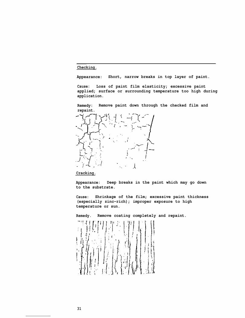
Checking.
Appearance: Short, narrow breaks in top layer of paint.
Cause: Loss of paint film elasticity; excessive paintapplied; surface or surrounding temperature too high duringapplication.
Remedy: Remove paint down through the checked film andrepaint.
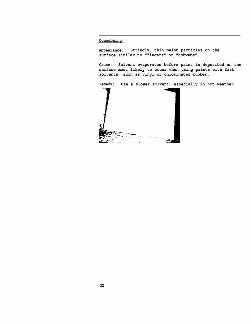
Cracking.
Appearance: Deep breaks in the paint which may go downto the substrate.
Cause: Shrinkage of the film; excessive paint thickness(especially zinc-rich); improper exposure to hightemperature or sun.
Remedy. Remove coating completely and repaint.
31
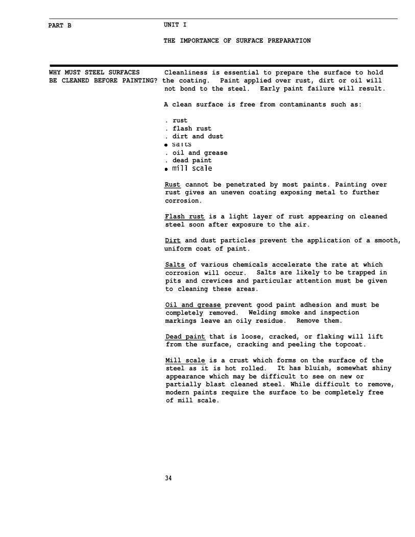
Cobwebbing.
Appearance: Stringly, thin paint particles on thesurface similar to "fingers" or "cobwebs".
Cause: Solvent evaporates before paint is deposited on thesurface most likely to occur when using paints with fastsolvents, such as vinyl or chlorinated rubber.
Remedy: Use a slower solvent, especially in hot weather.
32

PART B’SURFACE PREPARATION:THE KEY TOCOATING PERFORMANCE.
UNIT IIMPORTANCE OF SURFACEPREPARATION
UNIT IIHOW TO CHOOSE THE PROPERMETHOD FOR SURFACE PREPARATION
UNIT IllEQUIPMENT SET-UP FORNOZZLE BLASTING EFFICIENCY
UNIT IVEFFICIENT AND SAFE PRACTICESFOR SURFACE PREPARATION33
PART B UNIT I
THE IMPORTANCE OF SURFACE PREPARATION
WHY MUST STEEL SURFACES Cleanliness is essential to prepare the surface to holdBE CLEANED BEFORE PAINTING? the coating. Paint applied over rust, dirt or oil will
not bond to the steel. Early paint failure will result.
A clean surface is free from contaminants such as:
. rust
. flash rust
. dirt and dust
. oil and grease
. dead paint
Rust cannot be penetrated by most paints. Painting overrust gives an uneven coating exposing metal to furthercorrosion.
Flash rust is a light layer of rust appearing on cleanedsteel soon after exposure to the air.
Dirt and dust particles prevent the application of a smooth,uniform coat of paint.
Salts of various chemicals accelerate the rate at whichcorrosion will occur. Salts are likely to be trapped inpits and crevices and particular attention must be givento cleaning these areas.
Oil and grease prevent good paint adhesion and must becompletely removed. Welding smoke and inspectionmarkings leave an oily residue. Remove them.
Dead paint that is loose, cracked, or flaking will liftfrom the surface, cracking and peeling the topcoat.
Mill scale is a crust which forms on the surface of thesteel as it is hot rolled. It has bluish, somewhat shinyappearance which may be difficult to see on new orpartially blast cleaned steel. While difficult to remove,modern paints require the surface to be completely freeof mill scale.
34
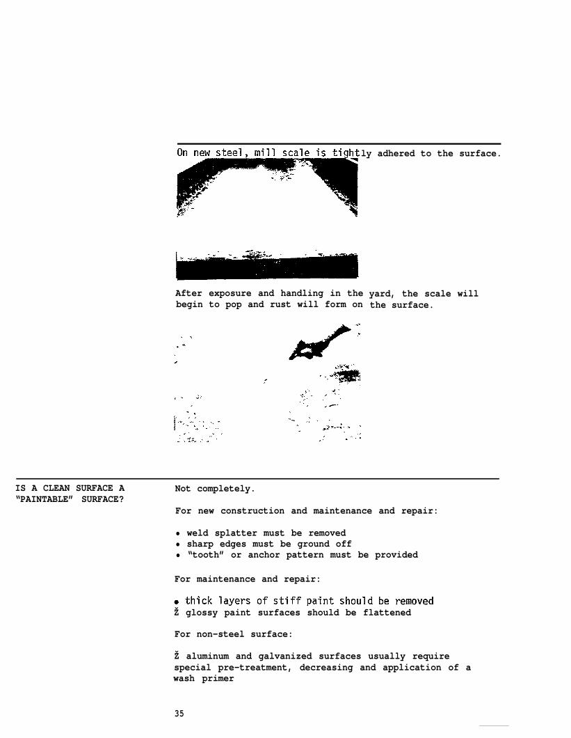
ly adhered to the surface.
After exposure and handling in thebegin to pop and rust will form on
yard, the scale willthe surface.
IS A CLEAN SURFACE A Not completely.“PAINTABLE” SURFACE?
For new construction and maintenance and repair:
• weld splatter must be removed• sharp edges must be ground off• “tooth” or anchor pattern must be provided
For maintenance and repair:
Ž glossy paint surfaces should be flattened
For non-steel surface:
Ž aluminum and galvanized surfaces usually requirespecial pre-treatment, decreasing and application of awash primer
35
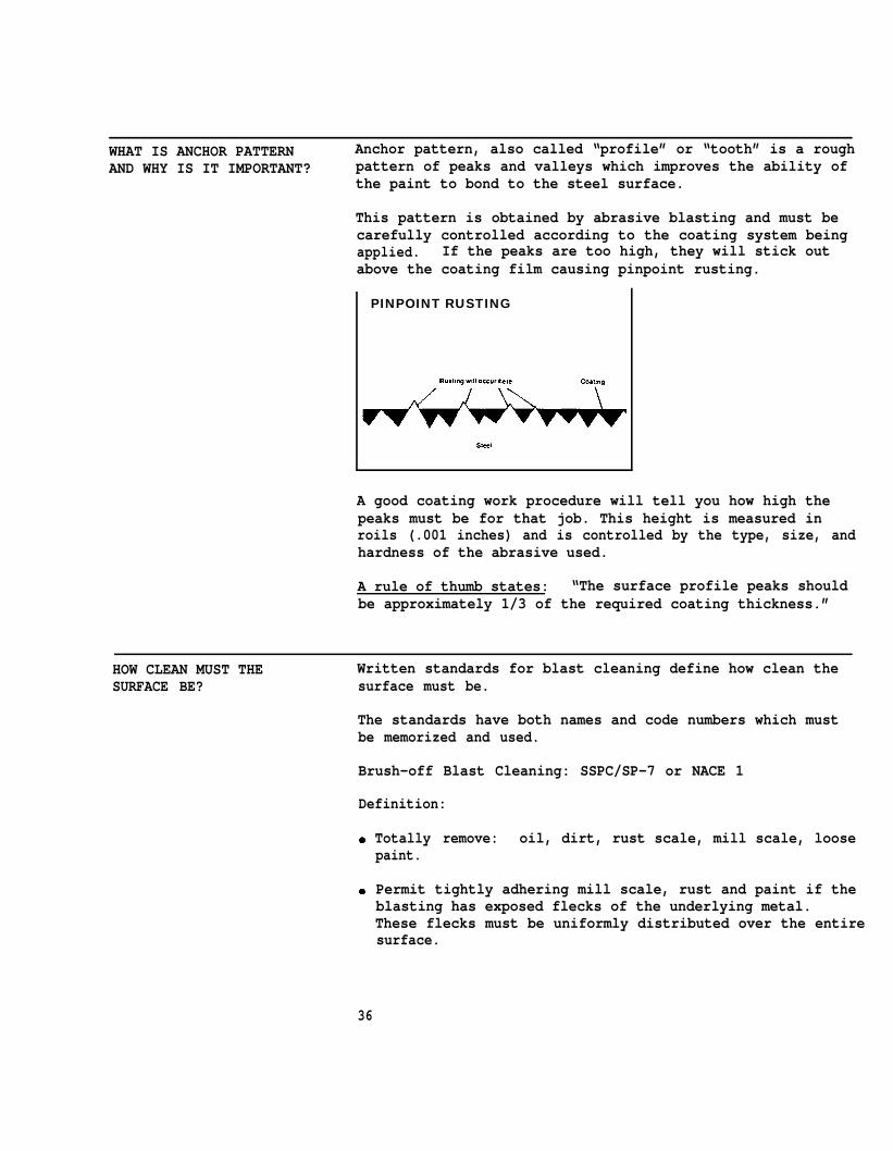
WHAT IS ANCHOR PATTERN Anchor pattern, also called “profile” or “tooth” is a roughAND WHY IS IT IMPORTANT? pattern of peaks and valleys which improves the ability of
the paint to bond to the steel surface.
This pattern is obtained by abrasive blasting and must becarefully controlled according to the coating system beingapplied. If the peaks are too high, they will stick outabove the coating film causing pinpoint rusting.
PINPOINT RUSTING
A good coating work procedure will tell you how high thepeaks must be for that job. This height is measured inroils (.001 inches) and is controlled by the type, size, andhardness of the abrasive used.
A rule of thumb states: “The surface profile peaks shouldbe approximately 1/3 of the required coating thickness.”
HOW CLEAN MUST THE Written standards for blast cleaning define how clean theSURFACE BE? surface must be.
The standards have both names and code numbers which mustbe memorized and used.
Brush-off Blast Cleaning: SSPC/SP-7 or NACE 1
Definition:
Totally remove: oil, dirt, rust scale, mill scale, loosepaint.
Permit tightly adhering mill scale, rust and paint if theblasting has exposed flecks of the underlying metal.These flecks must be uniformly distributed over the entiresurface.
36
Commercial Grade Blast Cleaning: SSPC/SP-6 or NACE 2
Definition:
Ž Remove all oil, dirt, rust scale, rust and mill scale and old paint.
Ž Slight shadows, streaks or stains from rust or mill scale oxide may remain. Slight rust or paint residue may remain in the bottom of the pits. At least 66 percent of each square inch of surface is free of all visible residues.
Near White Blast Cleaning: SSPC/SP-10 or NACE 3
Definition:
Completely remove all oil, dirt, mill scale, rust, paintor other foreign matter. Very light shadows or slightstreaks or discolorations may remain. At least 95 percentof each square inch of surface is free of all visibleresidues.
White Metal Blast Cleaning: SSPC/Sp-5 or NACE 4
Definition:
Remove all foreign matter.
Note:
Ž The surface has a gray-white uniform metallic color andis slightly roughened to form an anchor pattern.
• The color of the cleaned surface may be affected by theabrasive used.

PART B UNIT II
HOW TO CHOOSE THE PROPER METHOD FOR SURFACE PREPARATION
WHAT METHODS ARE AVAILABLE A variety of surface preparation methods are available toTO CLEAN THE SURFACE? shipyards:
• hand tool cleaningŽ power tool cleaningŽ solvent or chemical wash• steam cleaningŽ waterblasting• abrasive blast cleaning
Hand Tool Cleaning
Types: Scrapers, clippers, rust hammers, chisels, knives
Use:
• removal of loose paint, layers of loose rust, dried soilŽ spot cleaning small areas• maintenance priming before applying bituminous and
oleoresinous paints for
Disadvantages:
● slow● will not remove tightly
trapped in crevices, orŽ may raise burrs or dent
failure.
Power Tool Cleaninq
atmospheric exposures.
adhered contaminants, dirtoil and greasethe surface leading to paint
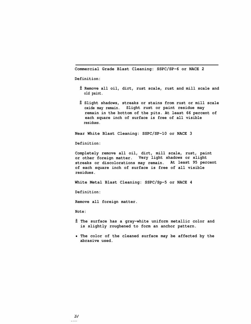
Types: Wire brushes, sanding discs, grinders, clippers,scalers, needle guns, rotary descalers
Use:
● removal of loose rust and scale
Ž preparation of post-erection welded surfacesŽ removal of old paint lifted by rustŽ suitable for small areas
Disadvantages:
ž cannot completely remove rust and scale● may polish surface if used at too high speed or kept on
one spot too long
38
CHIPPINGHAMMERS
39

Solvent Washing
Use:
• removal of oil and grease• removal dirt trapped in an oil film• pretreatment before mechanical cleaning
Disadvantages:
Ž no effect on rust or mill scaleŽ slow; hand laborŽ rags and solvent need constant replacement to avoid
leaving an oily residue
Steam Cleaning
Use:
● removal of dirt on top of existing paint● effective on heavy soil; often commercial detergents are
addedŽ cleans large areas more rapidly than solvent wiping
,.
Waterblasting
Use:
Ž removal of marine growth● removal of loose paint, dirt and light rust (sand may be
added to the water to improve cleaning)
Disadvantages:
● flash rusting● water and sand mixture may be difficult to remove
40
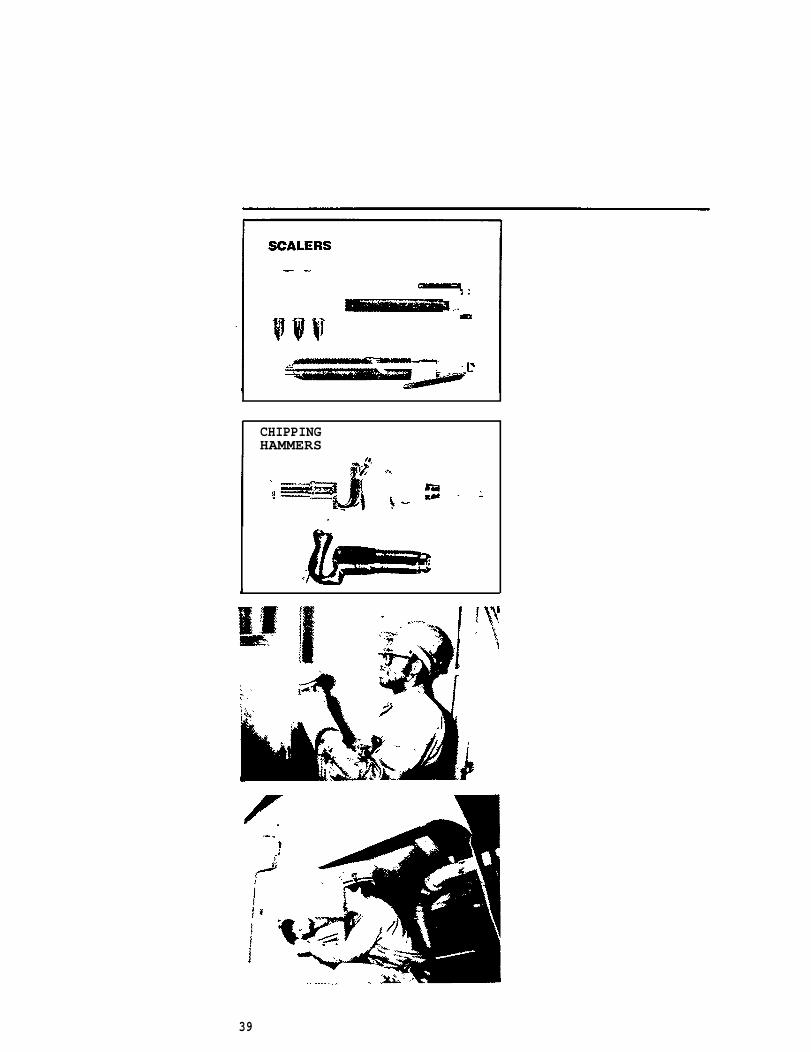
Abrasive Blast Cleaning
Use:
Ž recommended when steel must be totally clean and exposedŽ completely removes rust, mill scale and old paintŽ creates a controlled anchor pattern
Types:
●
●
●
nozzle blastingcentrifugal or wheel blastingvacu-bLasting
HOW TO CHOOSE THE RIGHT There are six factors to consider in choosing a cleaning -
CLEANING METHOD method.
1.
2.
3.
4.
41
The major factor is type and amount of contaminantpresent.
The original condition of the steel. Fabrication,handling, and storage conditions of new steel maycontribute to paint failure later on. Metalprojections around edges, punched holes, weldsplatter and chemical deposits must all be removed.The condition of old steel which may be badlyscarred or pitted will also determine which cleaningmethod is chosen.
The type of paint applied, its wetting properties andsurface profile requirements.
The size of the surface and structures to be cleaned.
i
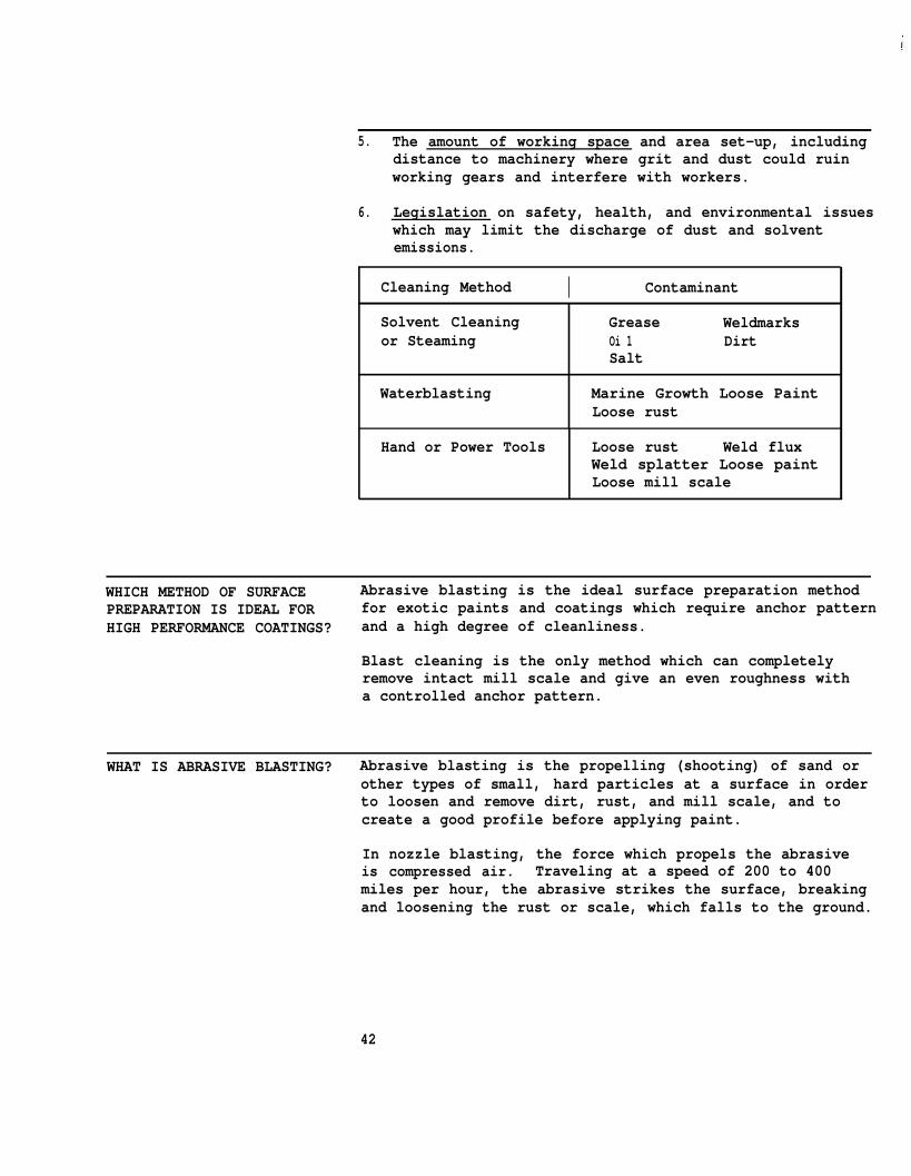
5. The amount of working space and area set-up, includingdistance to machinery where grit and dust could ruinworking gears and interfere with workers.
6. Legislation on safety, health, and environmental issueswhich may limit the discharge of dust and solventemissions.
Cleaning Method I Contaminant
Solvent Cleaning Grease Weldmarksor Steaming Oi 1 Dirt
Salt
Waterblasting Marine Growth Loose PaintLoose rust
Hand or Power Tools Loose rust Weld fluxWeld splatter Loose paintLoose mill scale
WHICH METHOD OF SURFACE Abrasive blasting is the ideal surface preparation methodPREPARATION IS IDEAL FOR for exotic paints and coatings which require anchor patternHIGH PERFORMANCE COATINGS? and a high degree of cleanliness.
Blast cleaning is the only method which can completelyremove intact mill scale and give an even roughness witha controlled anchor pattern.
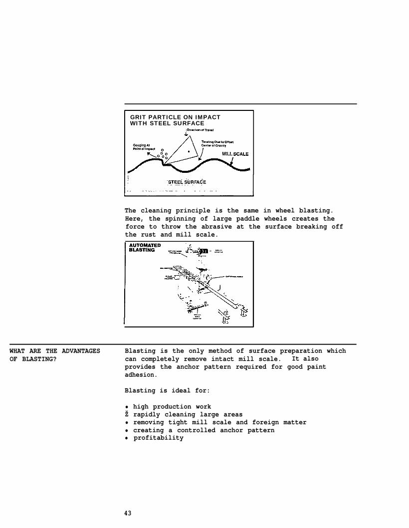
WHAT IS ABRASIVE BLASTING? Abrasive blasting is the propelling (shooting) of sand orother types of small, hard particles at a surface in orderto loosen and remove dirt, rust, and mill scale, and tocreate a good profile before applying paint.
In nozzle blasting, the force which propels the abrasiveis compressed air. Traveling at a speed of 200 to 400miles per hour, the abrasive strikes the surface, breakingand loosening the rust or scale, which falls to the ground.
42
GRIT PARTICLE ON IMPACTWITH STEEL SURFACE
The cleaning principle is the same in wheel blasting.Here, the spinning of large paddle wheels creates theforce to throw the abrasive at the surface breaking offthe rust and mill scale.
WHAT ARE THE ADVANTAGES Blasting is the only method of surface preparation whichOF BLASTING? can completely remove intact mill scale. It also
provides the anchor pattern required for good paintadhesion.
Blasting is ideal for:
• high production workŽ rapidly cleaning large areas• removing tight mill scale and foreign matter• creating a controlled anchor pattern• profitability
43
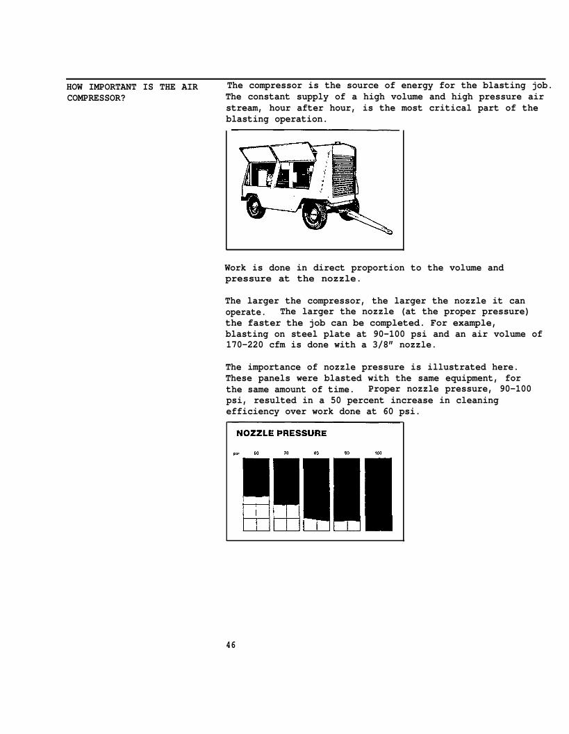
HOW IMPORTANT IS THE AIR The compressor is the source of energy for the blasting job.COMPRESSOR? The constant supply of a high volume and high pressure air
stream, hour after hour, is the most critical part of theblasting operation.
Work is done in direct proportion to the volume andpressure at the nozzle.
The larger the compressor, the larger the nozzle it canoperate. The larger the nozzle (at the proper pressure)the faster the job can be completed. For example,blasting on steel plate at 90-100 psi and an air volume of170-220 cfm is done with a 3/8” nozzle.
The importance of nozzle pressure is illustrated here.These panels were blasted with the same equipment, forthe same amount of time. Proper nozzle pressure, 90-100psi, resulted in a 50 percent increase in cleaningefficiency over work done at 60 psi.
46
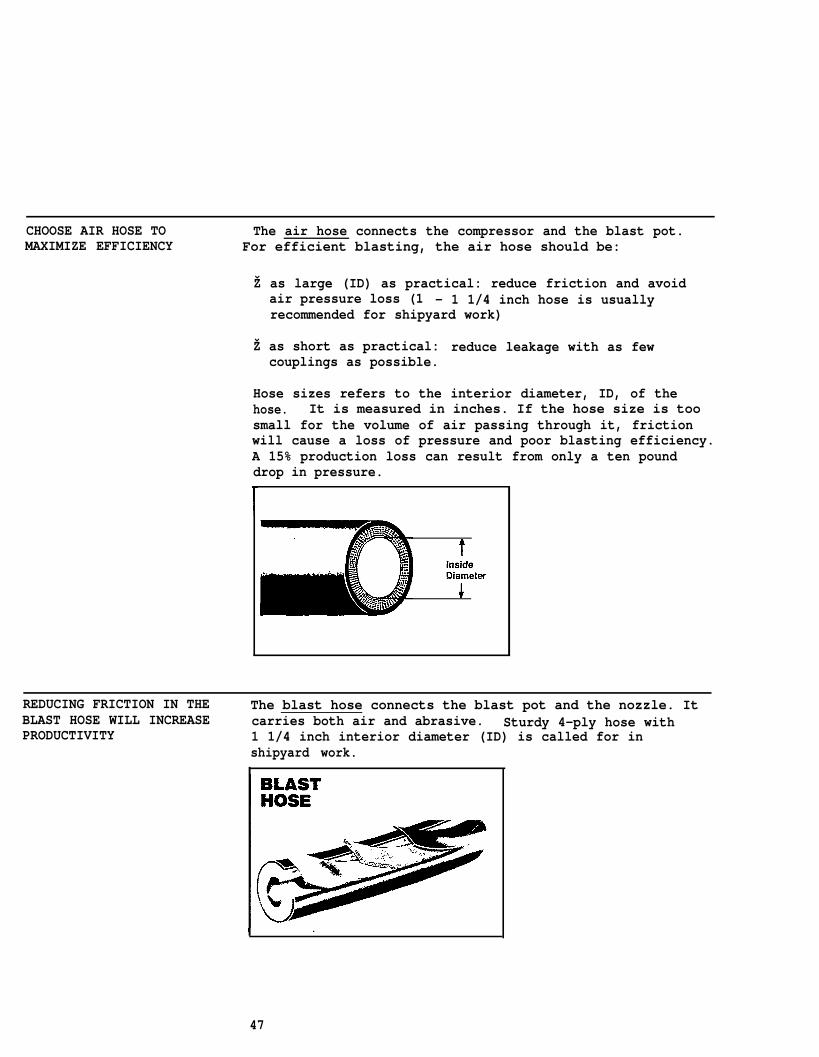
CHOOSE AIR HOSE TO The air hose connects the compressor and the blast pot.MAXIMIZE EFFICIENCY For efficient blasting, the air hose should be:
Ž as large (ID) as practical: reduce friction and avoidair pressure loss (1 - 1 1/4 inch hose is usuallyrecommended for shipyard work)
Ž as short as practical: reduce leakage with as fewcouplings as possible.
Hose sizes refers to the interior diameter, ID, of thehose. It is measured in inches. If the hose size is toosmall for the volume of air passing through it, frictionwill cause a loss of pressure and poor blasting efficiency.A 15% production loss can result from only a ten pounddrop in pressure.
REDUCING FRICTION IN THE The blast hose connects the blast pot and the nozzle. ItBLAST HOSE WILL INCREASE carries both air and abrasive. Sturdy 4-ply hose withPRODUCTIVITY 1 1/4 inch interior diameter (ID) is called for in
shipyard work.
47
ARE THERE ANY PROBLEMS In spite of its efficiency and good results, some problemsWITH BLASTING? still occur, such as
●
●
●
●
accumulation of used abrasives in tanks and bilges canbe difficult to remove
blowing dust and abrasive in the air can interfere withmachinery, or the work of nearby craftsmen
air borne dust can be harmfulrespirator must be worn whileabrasives are costly; recyclwherever possible --
These problems can be reducedequipment and proper planning
to the operator (a operating the equipment)ing should be considered
with correct use of theand scheduling.
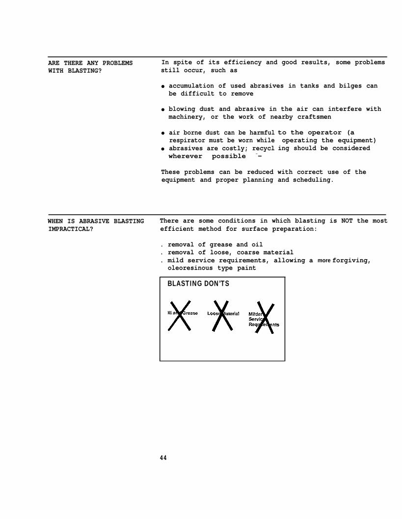
WHEN IS ABRASIVE BLASTING There are some conditions in which blasting is NOT the mostIMPRACTICAL? efficient method for surface preparation:
. removal of grease and oil
. removal of loose, coarse material
. mild service requirements, allowing a more forgiving,oleoresinous type paint
BLASTING DON’TS
44
PART B UNIT III
EQUIPMENT SET-UP FOR NOZZLE BLASTING EFFICIENCY
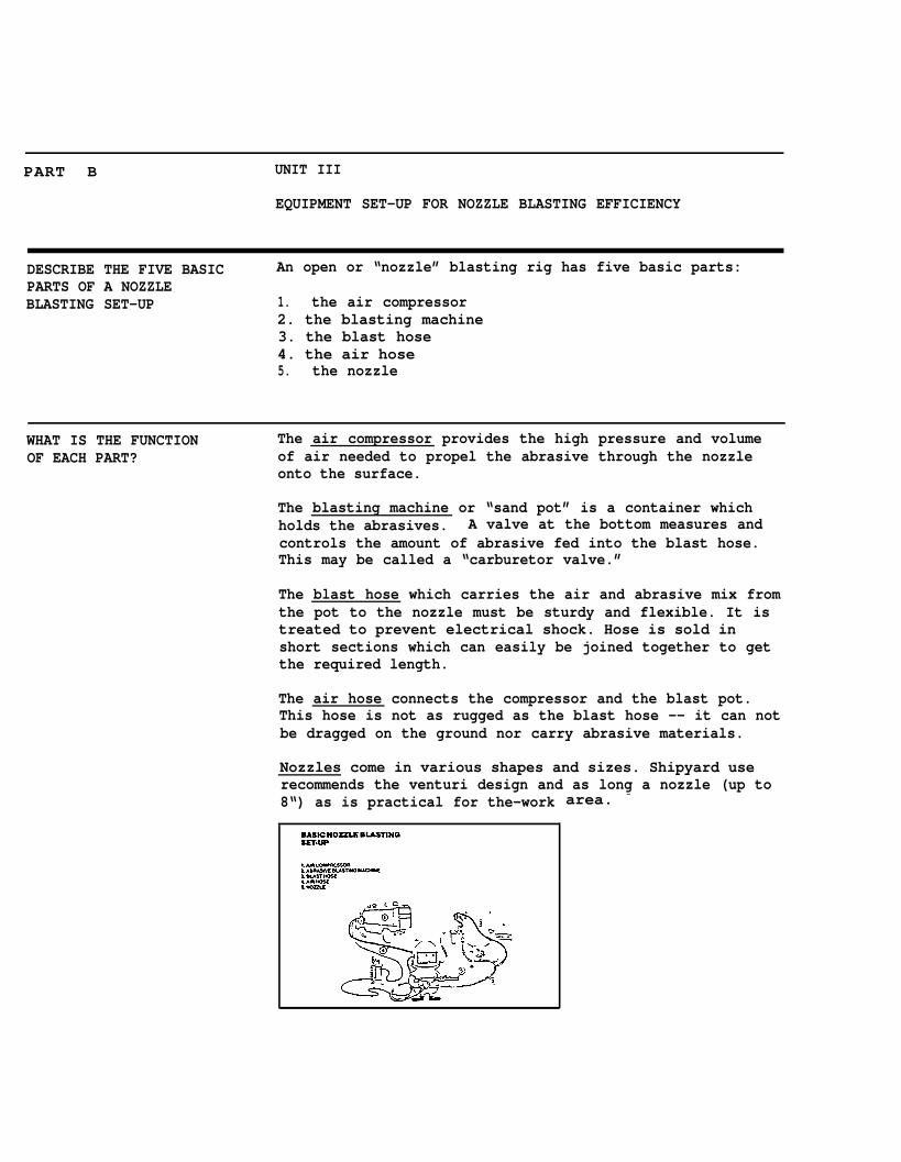
DESCRIBE THE FIVE BASIC An open or “nozzle” blasting rig has five basic parts:PARTS OF A NOZZLEBLASTING SET-UP 1. the air compressor
2. the blasting machine3. the blast hose4. the air hose5. the nozzle
WHAT IS THE FUNCTION The air compressor provides the high pressure and volumeOF EACH PART? of air needed to propel the abrasive through the nozzle
onto the surface.
The blasting machine or “sand pot” is a container whichholds the abrasives. A valve at the bottom measures andcontrols the amount of abrasive fed into the blast hose.This may be called a “carburetor valve.”
The blast hose which carries the air and abrasive mix fromthe pot to the nozzle must be sturdy and flexible. It istreated to prevent electrical shock. Hose is sold inshort sections which can easily be joined together to getthe required length.
The air hose connects the compressor and the blast pot.This hose is not as rugged as the blast hose -- it can notbe dragged on the ground nor carry abrasive materials.
Nozzles come in various shapes and sizes. Shipyard userecommends the venturi design and as long a nozzle (up to8“) as is practical for the-work area. -
A short length of lighter, more flexible,2-ply hose with a 3/4 inch ID is sometimes joined in atthe nozzle. These sections, called “whips,” are easy tohandle and are effective for work in areas with manyangles, pipes, and stiffeners.
Avoid using whips in general shipyard work. They addlength and the small interior diameter reduces pressure.Whips cancel the advantages gained by the large size blasthose.
Rule of Thumb: Bigger and shorter are the key to air andblast hose efficiency. If a choice must be made betweenhaving a short air hose or a short blast hose, choose theshort blast hose.
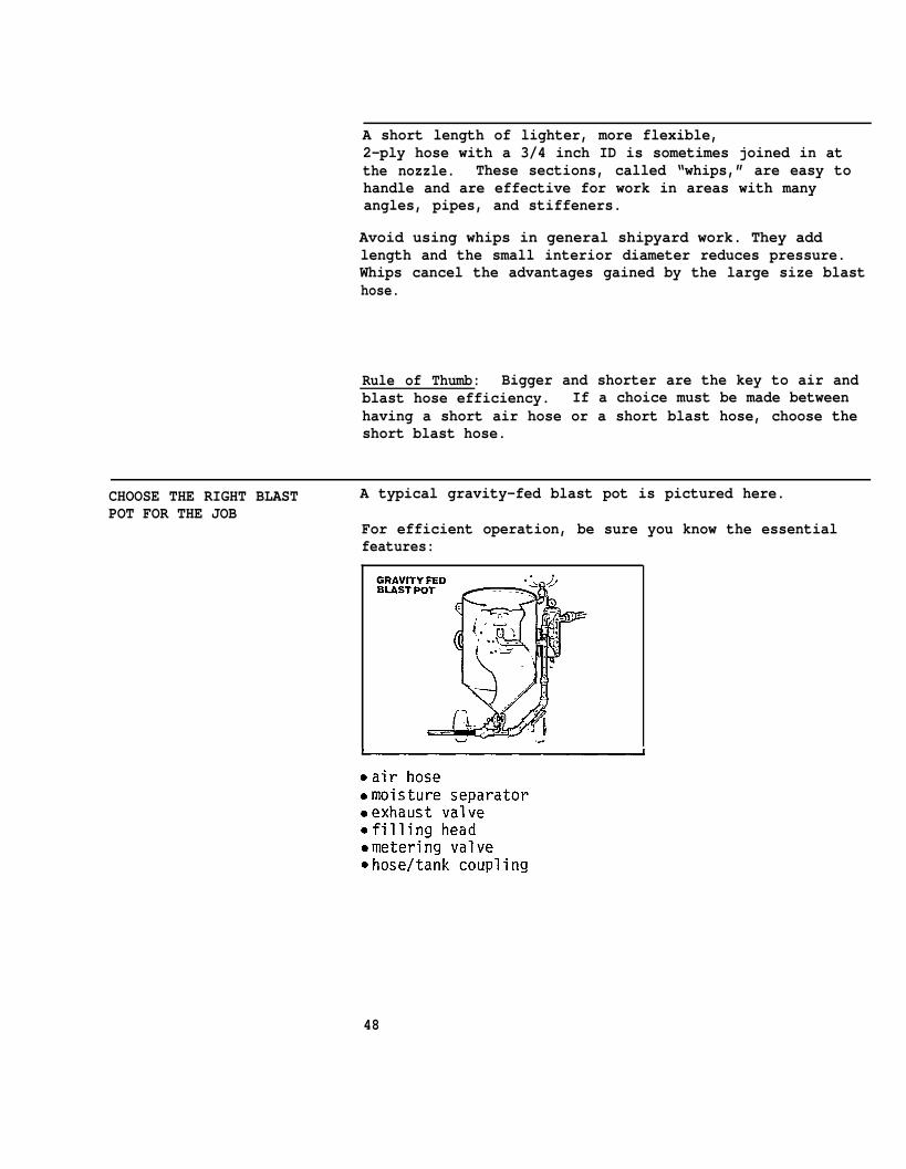
CHOOSE THE RIGHT BLASTPOT FOR THE JOB
A typical gravity-fed blast pot is pictured here.
For efficient operation, be sure you know the essentialfeatures:
48

Efficient blasting depends upon:
Proper abrasive flow is controlled by the metering valve.Some pots have an automatic valve which adjusts the flowrate as the air pressure changes.
HOW DOES NOZZLE SIZE AFFECT The nozzle is a major tool in the blasting operation.WORK EFFICIENCY? Surface cleaning is done in direct proportion to the
volume of air pushed through the nozzle at high pressure.For example: If 100 square feet per hour can be obtainedwith a 1/4” nozzle, 400 square feet per hour can beobtained with 1/2” nozzle. However, a nozzle can betoo large for the air volume: Air will escape causing thepressure and production to drop.
Nozzles come in an assortment of lengths, sizes of opening,and lining materials. Because of the heavy demands ofshipyard work, it is recommended that nozzles have thefollowing characteristics:
●
●
●
●
venturi designlong nozzle lengthTungsten Carbide or Norbide lininglarge orifice size
49
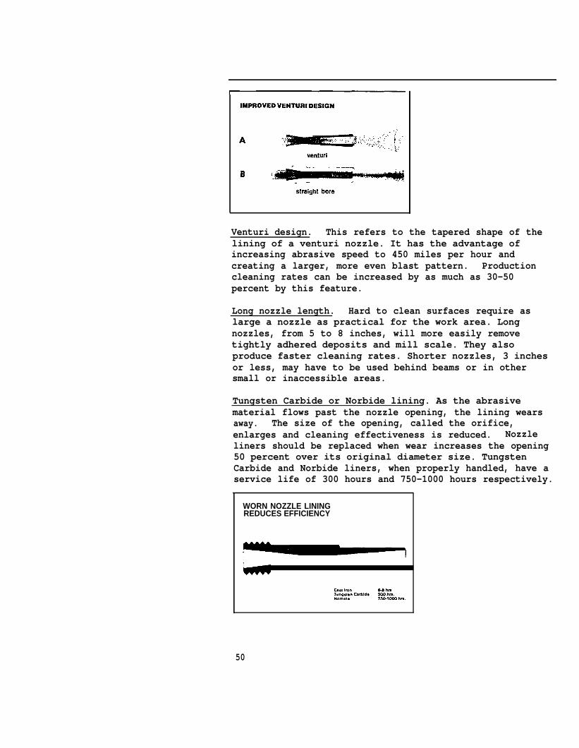
Venturi design. This refers to the tapered shape of thelining of a venturi nozzle. It has the advantage ofincreasing abrasive speed to 450 miles per hour andcreating a larger, more even blast pattern. Productioncleaning rates can be increased by as much as 30-50percent by this feature.
Long nozzle length. Hard to clean surfaces require aslarge a nozzle as practical for the work area. Longnozzles, from 5 to 8 inches, will more easily removetightly adhered deposits and mill scale. They alsoproduce faster cleaning rates. Shorter nozzles, 3 inchesor less, may have to be used behind beams or in othersmall or inaccessible areas.
Tungsten Carbide or Norbide lining. As the abrasivematerial flows past the nozzle opening, the lining wearsaway. The size of the opening, called the orifice,enlarges and cleaning effectiveness is reduced. Nozzleliners should be replaced when wear increases the opening50 percent over its original diameter size. TungstenCarbide and Norbide liners, when properly handled, have aservice life of 300 hours and 750-1000 hours respectively.
WORN NOZZLE LININGREDUCES EFFICIENCY
50
-.
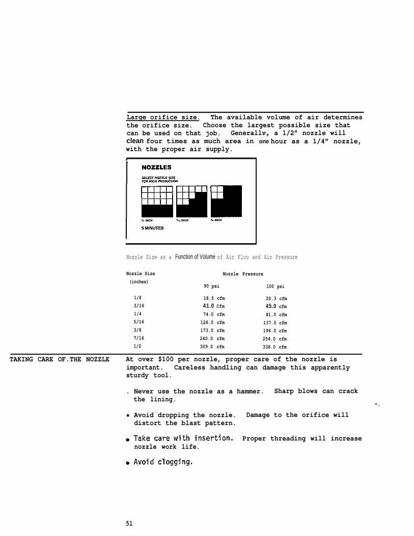
Large orifice size. The available volume of air determinesthe orifice size. Choose the largest possible size thatcan be used on that job. Generallv, a 1/2” nozzle willclean four times as much area inwith the proper air supply.
t
- -one hour as a 1/4” nozzle,
Nozzle Size as a Function of Volume of Air Flou and Air Pressure
Nozzle Size Nozzle Pressure(inches)
90 psi 100 psi
1/8 18.5 cfm 20.3 cfm3/16 41.0 Cfm 45.0 cfm1/4 74.0 cfm 81.0 cfm5/16 126.0 cfm 137.0 cfm3/8 173.0 cfm 196.0 cfm7/16 240.0 cfm 254.0 cfm1/2 309.0 cfm 338.0 cfm
TAKING CARE OF.THE NOZZLE At over $100 per nozzle, proper care of the nozzle isimportant. Careless handling can damage this apparentlysturdy tool.
. Never use the nozzle as a hammer. Sharp blows can crackthe lining.
• Avoid dropping the nozzle. Damage to the orifice willdistort the blast pattern.
Proper threading will increasenozzle work life.
51
TIPS FOR MAINTAINING ●
BLASTING EFFICIENCY
●
●
●
●
●
●
Place the compressor near the blasting job, as near aspossible to the blast pot. Position it so that wind willblow blasting dust away from the compressor, assuringclean air intake.
Run large air hose from the compressor to the blast pot.Large hose reduces friction in the line.
Care for the equipment. Allow the compressor to warm upfor 10-15 minutes before starting to blast. Set it at120 pounds. DO NOT exceed 125 pounds. DO NOT overload.
Keep the compressor clean. Fans, radiators and filtersshould not be clogged with dirt or they will overheatand overload.
Check the compressor output every 6 months. An “orificegage” is available for this purpose.
Use external couplings when attaching hoses.
Keep hoses as short as possible to minimize pressurel o s s .
Mlake 1 1/4 inch ID air hose standardinch ID whip only in areas with manywhere greater flexibility is a must.
Avoid small sandblast hose.
practice. Use a 3/4angles or stiffeners
Rule of Thumb: The ID (interior diameter) of the airblasthose should be three to four times the orifice size ofthe nozzle.
Run hose in a straight line. Avoid 90 degree bends. Ifthe hose must curve around an object, use a long curve.Consider safety as well as productivity. Sharp curvescreate rapid wear and could cause a blow out.
Check for nozzle orifice wear.
52
PART B UNIT IV
EFFICIENT AND SAFE PRACTICES FOR SURFACE PREPARATION
GOOD BLASTING TECHNIQUE For effective nozzle operation, the blaster must determineand maintain the
• proper angle of attack, and• proper distance between the nozzle and the surface.
Experience is the best teacher. Experimentation withdifferent angles and distances when starting a new job willdetermine what is more effective for that surface condition.Once the most efficient angle and distance are determined,the blaster should maintain them with each pass during theentire operation.
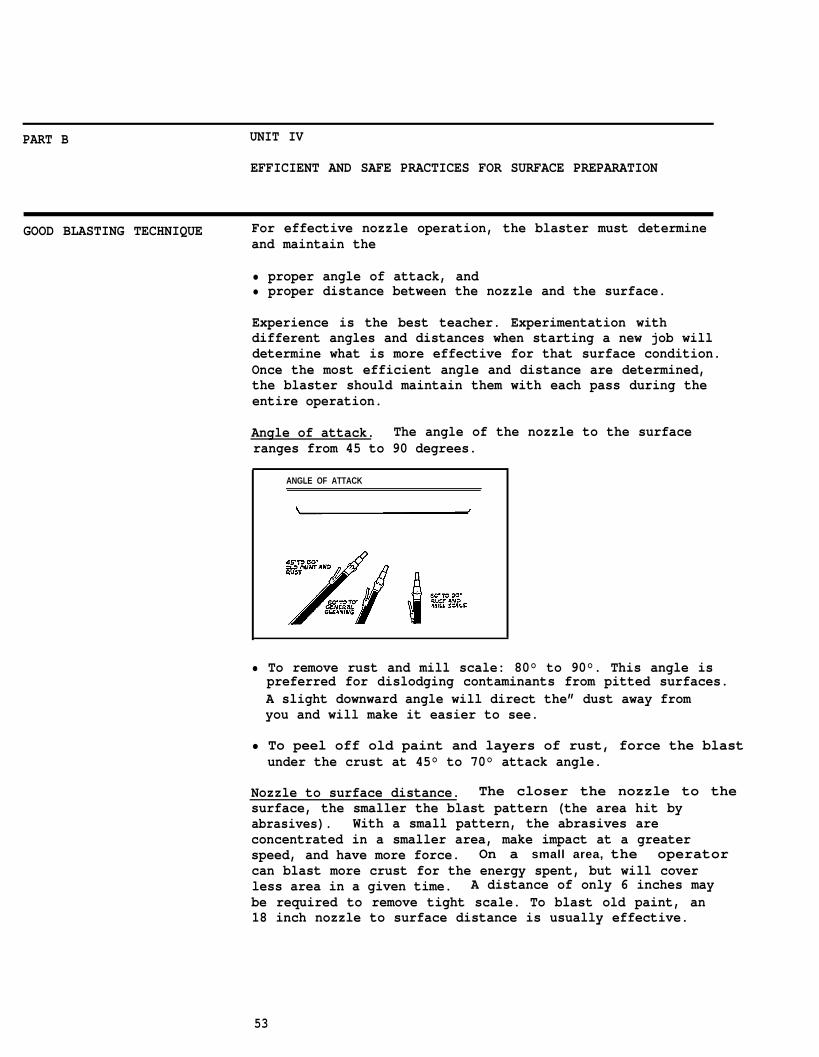
Angle of attack. The angle of the nozzle to the surfaceranges from 45 to 90 degrees.
ANGLE OF ATTACK
• To remove rust and mill scale: 80° to 90°. This angle ispreferred for dislodging contaminants from pitted surfaces.A slight downward angle will direct the” dust away fromyou and will make it easier to see.
• To peel off old paint and layers of rust, force the blastunder the crust at 45° to 70° attack angle.
Nozzle to surface distance. The closer the nozzle to the surface, the smaller the blast pattern (the area hit byabrasives). With a small pattern, the abrasives areconcentrated in a smaller area, make impact at a greaterspeed, and have more force. On a small area, the operator can blast more crust for the energy spent, but will coverless area in a given time. A distance of only 6 inches maybe required to remove tight scale. To blast old paint, an18 inch nozzle to surface distance is usually effective.
53

Each pass should be straight andproduce work of uniform quality.or varying the distance from the
at the sameThere should
surface.
distance tobe no arcing
WHAT HAPPENS IF THE The deadman remote control valve, placed close to theBLASTER MUST SUDDENLY STOP nozzle is designed for the blaster’s safety. Always useWORKING OR LOSES CONTROL this valve. Do not tie it down or fix it in the "on” OF THE NOZZLE? position. When the valve is released, it shuts down the
entire blasting operation. This eliminates the need for asecond person to watch the blast pot and stop the operation.
54
It increases the blaster’s control at the nozzle. If itis improperly used, the blaster loses control, and couldresult in the loss of life or limb. Blasting equipmentshould be used with care and should also be shut downbefore clearing an obstruction in the hose or tank.
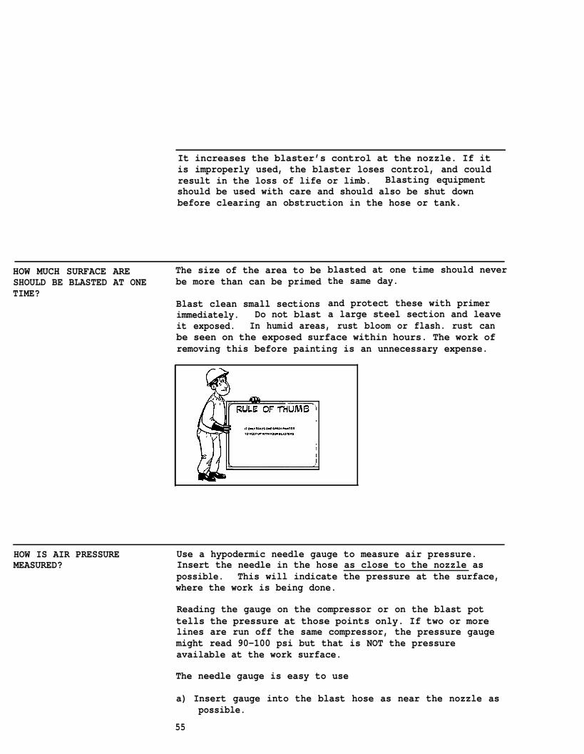
HOW MUCH SURFACE ARE The size of the area to beSHOULD BE BLASTED AT ONE be more than can be primedTIME?
Blast clean small sectionsimmediately. Do not blastit exposed. In humid areas, rust bloom or flash. rust canbe seen on the exposed surface within hours. The work ofremoving this before painting is an unnecessary expense.
blasted at one time should neverthe same day.
and protect these with primera large steel section and leave
HOW IS AIR PRESSURE Use a hypodermic needle gauge to measure air pressure.MEASURED? Insert the needle in the hose as close to the nozzle as
possible. This will indicate the pressure at the surface,where the work is being done.
Reading the gauge on the compressor or on the blast pottells the pressure at those points only. If two or morelines are run off the same compressor, the pressure gaugemight read 90-100 psi but that is NOT the pressureavailable at the work surface.
The needle gauge is easy to use
a) Insert gauge into the blast hose as near the nozzle aspossible.
55
b) The needle must point in the direction of the abrasiveflow.
c) Measurement is made while the abrasive is flowing togive a true reading of the pressure of the air/abrasivemix which hits the surface.
d) Check the readings at the start of every shift.
HOW IS THE QUALITY OF THE Air which carries dirt and oil defeats the purpose of blastAIR SUPPLY MAINTAINED? cleaning. The air, as well as the abrasive, must be clean
and oil-free. Water in the blast stream can cause spotrusting on steel.
Water and oil separators on the compressor and blast potwill solve the problem. They require regular attention.
KEEP OIL AND MOISTURE AWAY • Prevent contamination of the cleaned surface, andFROM ABRASIVE MATERIAL • Prevent clogging of the blast nozzle.
Keep the abrasives clean and dry.
Abrasives carrying oil or water will stain and spot rust asteel surface. The cleanliness needed for paint to bondcannot be achieved. If sand is the abrasive, it may mixwith water to clog the hose and nozzle.
To check the cleanliness of the abrasive, place a smallamount of abrasive in a glass jar filled with water.Shake the jar. If an oil film appears on the surface ofthe water, the abrasive is not clean and should not beused.
56
HOW DO YOU JUDGE THE PROPER An air stream from the nozzle should be a blue color. TheBALANCE OF ABRASIVE AND AIR? abrasive will cause a slight change in color. This
usually indicates a proper mix. Experience is the bestteacher here.
Operators tend to use too much abrasive. This cuts downblasting speed, creates excess dust, and increases clean-upcosts . Vary the mix by adjusting the metering valve.
SAFETY IS YOUR Major safety and health hazards faced by blasters include:RESPONSIBILITY
respiratory problemstoxic effectsskin diseaseburnseye injuryhearing lossfire and explosionequipment accidents
While these potential hazards exist on each, or site, thereare also many safety measures which can be taken to avoidaccidents and illnesses.
Understanding the function and capabilities of protectivedevices is your responsibility. Your health depends onusing these devices correctly.
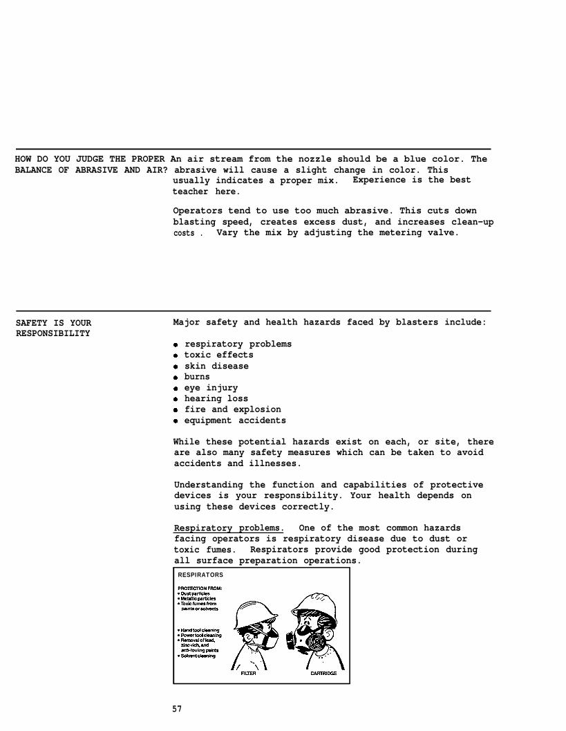
Respiratory problems. One of the most common hazardsfacing operators is respiratory disease due to dust ortoxic fumes. Respirators provide good protection duringall surface preparation operations.RESPIRATORS
57
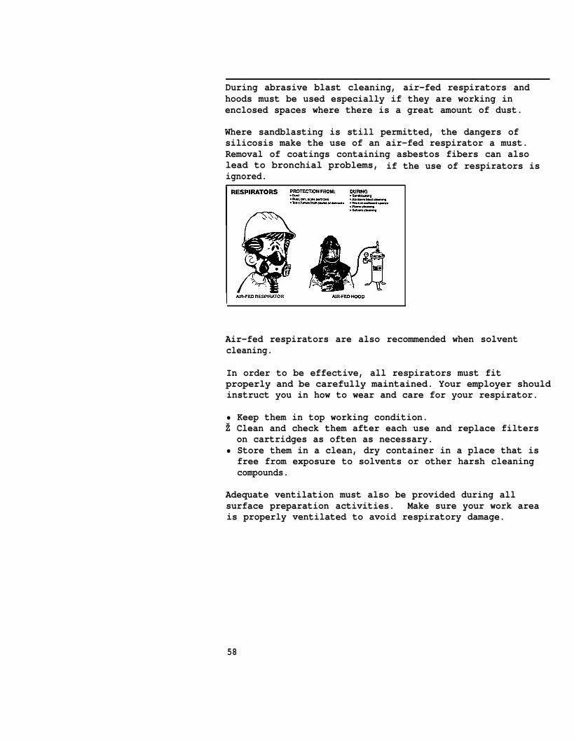
During abrasive blast cleaning, air-fed respirators andhoods must be used especially if they are working inenclosed spaces where there is a great amount of dust.
Where sandblasting is still permitted, the dangers ofsilicosis make the use of an air-fed respirator a must.Removal of coatings containing asbestos fibers can alsolead to bronchial problems, if the use of respirators isignored.
Air-fed respirators are also recommended when solventcleaning.
In order to be effective, all respirators must fitproperly and be carefully maintained. Your employer shouldinstruct you in how to wear and care for your respirator.
• Keep them in top working condition.Ž Clean and check them after each use and replace filters
on cartridges as often as necessary.• Store them in a clean, dry container in a place that is
free from exposure to solvents or other harsh cleaningcompounds.
Adequate ventilation must also be provided during allsurface preparation activities. Make sure your work areais properly ventilated to avoid respiratory damage.
58

Toxic effects. Toxic, or poisonous, substances and fumescan enter the body in several ways. They can be inhaled, swallowed, and absorbed through the skin.
Damage to the nervous and digestive systems may not benoticed for many years. Long range effects may appear aslung diseases such as silicosis and certain forms of cancer.
Other toxic effects are immediate. Symptoms such asheadaches, coughing, rashes and dizziness appear soon aftercontact with a poisonous substance.
Proper choice and consistent use of respirators andprotective creams and clothing shield the body from theseharmful substances. Adequate ventilation in the work areaalso reduces exposure to problem substances.
Skin disease. Skin irritation is a common problem amongblasters. Skin rashes, also called dermatitis, can resultfrom direct contact with an irritating chemical or certainmetallic dusts. Lead poisoning can be caused by absorbingtoxic dust through the skin. In chemical cleaning, burnsand dermatitis can result from contact with chromates orchromic acid.
59
Skin irritations can be prevented by using protective skincreams and protective clothing, including heavy duty gloves.Abrasive blast cleaning also demands the use of protectiveclothing to protect all parts of the body from irritatingdusts and abrasive bounce-back.
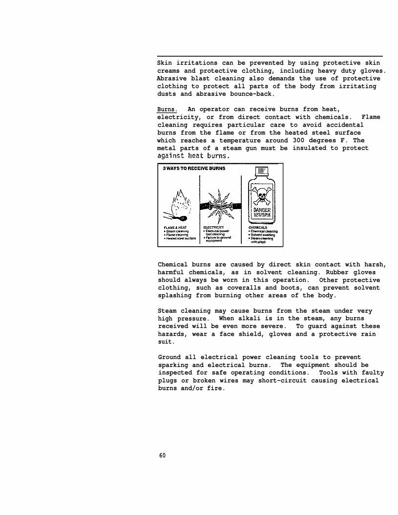
Burns. An operator can receive burns from heat,electricity, or from direct contact with chemicals. Flamecleaning requires particular care to avoid accidentalburns from the flame or from the heated steel surfacewhich reaches a temperature aroundmetal parts of a steam gun must be
300 degrees F. Theinsulated to protect
Chemical burns are caused by direct skin contact with harsh,harmful chemicals, as in solvent cleaning. Rubber glovesshould always be worn in this operation. Other protectiveclothing, such as coveralls and boots, can prevent solventsplashing from burning other areas of the body.
Steam cleaning may cause burns from the steam under veryhigh pressure. When alkali is in the steam, any burnsreceived will be even more severe. To guard against thesehazards, wear a face shield, gloves and a protective rainsuit.
Ground all electrical power cleaning tools to preventsparking and electrical burns. The equipment should beinspected for safe operating conditions. Tools with faultyplugs or broken wires may short-circuit causing electricalburns and/or fire.
60

Eye injury. In 1976, 21,000 eye injury cases werereported by workers in nine states. Potential eyeinjuries include:
Ž impact (eyes struck by or against objects)• chemical splash• eye scratches and abrasions
Eye protection is an important precaution that must betaken during any surface preparation operation where thereis a danger of flying particles or chips which can blindor cause other serious injuries. Wear safety goggles whenusing either hand or power tools. Safety goggles can alsoprevent dangerous solvents from splashing into eyes duringchemical cleaning. Flame cleaning operations also requirethe use of safety goggles.
Hoods provide a greater degree of protection from dust andflying particles, shielding the eyes, face, neck and ears.In blasting, they protect your eyes and head fromabrasive ricochet.
61

Hearing loss. Hearing loss can occur from exposure to highnoise levels for long periods of time. In 1976, 328 workersexperienced some loss of hearing in two states alone.Similar job-related cases were reported in the other 48states.
taking place.
twove
is are
Fire and explosion. The possibility of fire and explosionsis a safety hazard faced by all surface preparationoperators. Hand and power tools must be non-sparking andexplosion-proof, especially in the presence of combustiblevapors. Some abrasives can cause sparks when the particlesstrike the surface. If work is being done in a confinedarea, such as a tank, it must be proven gas-free. Sparksflying in an area containing flammable materials orcombustible vapors present a potential explosion or firehazard.
62
In the use of chemical cleaning agents or volatile solvents,adequate ventilation is ALWAYS called for.
OSHA requirements state that “suitable fire extinguishingequipment shall be immediately available in the work areaand shall be maintained (ready) for instant use.”
Equipment accidents. Safe use of all surface preparationequipment will reduce the occurrence of accidents. Allequipment should be inspected for good working condition.
In accordance with OSHA rules, faulty hand and power tools,such as cracked grinders and wheels or broken wires cancause serious injury to an operator. All power equipmentshould be held correctly and operated at the speedrecommended by the manufacturer. Where necessary, toolsshould be effectively grounded.
The pressure of the tank used in abrasive blast cleaningmust be carefully watched to make sure it does not exceedthe maximum allowable pressure for the pot. “Sandpots”fall under the category of unfired pressure vessels andmust meet certain standards.
During solvent cleaning, take care not to splash thechemicals. Machinery parts will be destroyed andscaffolding ropes could be weakened, resulting in seriousaccidents.
Electric shock can occur in certain situations. In blastcleaning, the nozzle should be grounded so it will notdischarge high static electricity and shock the blaster.The shock itself is not lethal but falling off a scaffoldmay be.
In waterblasting, electric shock can be conducted throughwet surfaces. All electrical operations should be shut down when waterblasting is in process.
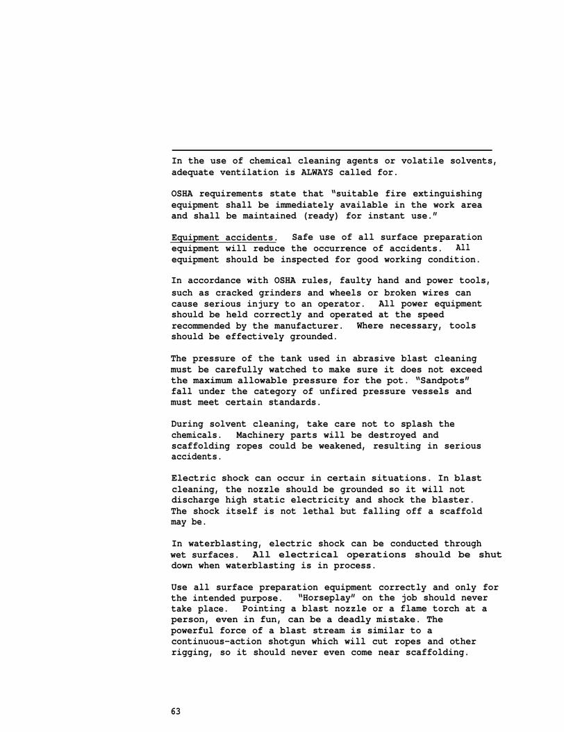
Use all surface preparation equipment correctly and only forthe intended purpose. “Horseplay” on the job should nevertake place. Pointing a blast nozzle or a flame torch at aperson, even in fun, can be a deadly mistake. Thepowerful force of a blast stream is similar to acontinuous-action shotgun which will cut ropes and otherrigging, so it should never even come near scaffolding.
63
Never point powerful equipment at anything other than thesurface to be cleaned.
The use of safety belts and lines-is an obvious precautionto take in any number of blasting situations above or belowground. Often their use is required by law. This is truewhen a blaster is working in a ship’s hold or inside achemical tank or grain elevator -- any situation where theblaster.must be removed quickly in case of an emergency.
Where-rigging of any kind --scaffolding, swing stages,boatswain chairs, slings -- is used, safety belts and linesshould have substantial guard rails. The force in ablasting pass tends to push, the operator backward. Mostblasters are aware of this force and stand in a bracedposition to lessen its impact on them. Safety measuresinclude back rails, stabilizing lines, and sure footing.
Should an accident occur, you should know where emergencyphone numbers are posted and where emergency equipment andsupplies are located. OSHA requires that a first aid kitis provided for each vessel that is being worked on.At least one employee should be qualified to give firstaid, if there is no separate first aid room or healthattendant.
Blasters and other operators should be aware of the dangerswhich are possible in their jobs. However, safe use ofequipment and other precautions will prevent accidents fromoccurring. Thorough safety training is essential forefficient and productive workers.
64

PART CPAINT APPLICATION:TECHNIQUESAND PRACTICES.
READY TO
UNIT IICOMMON METHODS OFSHIPYARD PAINT APPLICATION
UNIT IllSET UP AND EFFICIENTOPERATION OF SPRAY EQUIPMENT
UNIT IVGOOD SPRAYING PRACTICES
UNIT VSAFETY AND HEALTH MEASURESIN PAINT SPRAY APPLICATION65
PART C UNIT I
GETTING READY TO PAINT
PROPER PAINT STORAGE Paints are sensitive chemical compounds which must be storedand handled with care.
Proper paint storage can:
• eliminate fire hazards and the danger of explosion, and• eliminate the waste of costly materials
Store paints in a separate room or building away from thework area.
Avoid: • excess heat• direct sunlight• sparks or flame• freezing temperatures
Good practices:
rotate stock: a first in first out method is bestkeep the room well ventilatedmonitor the temperaturestore cans on palletskeep dry and clean: labels must stay attached so that thecontents are easily identifiedkeep sealed until ready to use: air and dirt shorten theshelf life -- use cans that have been opened forinspection or cans which have been partially used beforethe unopened cans
Avoid wasting paint through poor storage. At $30 pergallon, the yard can’t afford many discards.
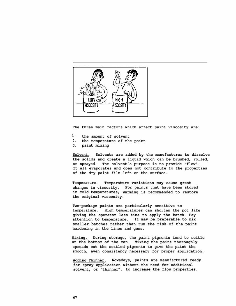
VISCOSITY: Paint consistency or “viscosity” is a measurement of how theWHAT IS IT? material flows. A high viscosity paint is thicker and flowsHOW IS IT CONTROLLED? more slowly than a low viscosity paint.
The proper viscosity is essential for proper film build.It is also an important factor in:
• selecting the right equipment for spray application,• obtaining good spray atomization, and• obtaining satisfactory flow and leveling properties.
66
1.
The three main factors which affect paint viscosity are:
the amount of solvent2. the temperature of the paint3. paint mixing
Solvent. Solvents are added by the manufacturer to dissolvethe solids and create a liquid which can be brushed, rolled,or sprayed. The solvent’s purpose is to provide “flow”.It all evaporates and does not contribute to the propertiesof the dry paint film left on the surface.
Temperature. Temperature variations may cause greatchanges in viscosity. For paints that have been storedin cold temperatures, warming is recommended to restorethe original viscosity.
Two-package paints are particularly sensitive totemperature. High temperatures can shorten the pot lifegiving the operator less time to apply the batch. Payattention to temperature. It may be preferable to mixsmaller batches rather than run the risk of the paint hardening in the lines and guns.
Mixing. During storage, the paint pigments tend to settleat the bottom of the can. Mixing the paint thoroughlyspreads out the settled pigments to give the paint thesmooth, even consistency necessary for proper application.
Adding Thinner. Nowadays, paints are manufactured readyfor spray application without the need for additionalsolvent, or “thinner”, to increase the flow properties.
67

Use thinner only if the manufacturer’s data sheet specifies
reduce hiding powerprovide inadequate corrosion protection cause runs and sagsrequire repainting: extra work and extra costscreate excessive spray fog, endangering the painter’shealth
or
l o w.
Some new exotic paints reach theshaking or stirring. They would
proper viscosity bybe destroyed by the
addition of thinner. When the lid is removed, these paintsappear gel-like. A stick plunged into the center of thematerial would leave a hole when removed. However, withproper stirring the material becomes less thick (lessviscose) and flows easily.
These paints are “thixotropic” or “false bodied”. Followthe manufacturer’s instructions for stirring. Apply whenthe consistency is similar to heavy molasses. DO NOT ADDTHINNER.
WHY IS PAINT MIXING Paint mixing is critical to ensure that the protectiveCRITICAL? qualities of the paint are distributed throughout the
coating film. Failure to mix in all of the solids upsetsthe chemical balance. For example, leaving zinc dust at
68

Proper mixing is also important to remove lumps which mayclog the spray equipment.
For paints with very heavy pigments, such as inorganic zincand anti-foulants, constant agitation is required to keepthe pigments from falling to the bottom of the can afterthe paint is thoroughly mixed.
TIPS FOR MIXING ONE- Paint can be mixed manually or mechanically. For a smallPACKAGE PAINTS amount of paint (up to 5 gallons) manual mixing is
satisfactory.
For paint that comes in one container, mixing involvesthese steps:
Step 1. Pour off the thin portion of the paint into a cleancontainer.
Step 2. Stir the settled portion with a strong, cleanpaddle to break up the settled pigment.
Step 3. Break the lumps by rubbing them against the insideof the can.
Step 4. Use a figure 8 motion to mix thoroughly.
Step 5. Follow with a lifting and beating motion.
Step 6. Gradually return the thin, poured-off portion tothe original container while continuing to stir.
Step 7. When paint appears to be thoroughly mixed, it is“boxed”. To box, pour the paint back and forthbetween the two containers until it reaches asmooth, even consistency.
Remember:
●
●
●
Never use an air hose to mix paint. The air drives offthe solvents causing a change in viscosity. Furthermore,the air cannot lift heavy pigments -- they remain at thebottom of the paint can.
Mix only as much paint as necessary for a day’s work.
Do not leave paint in buckets or spray pots overnight.Gather the unused paint and put it-into-one coveredcontainer. Re-mix the paint thoroughly before using thenext day.
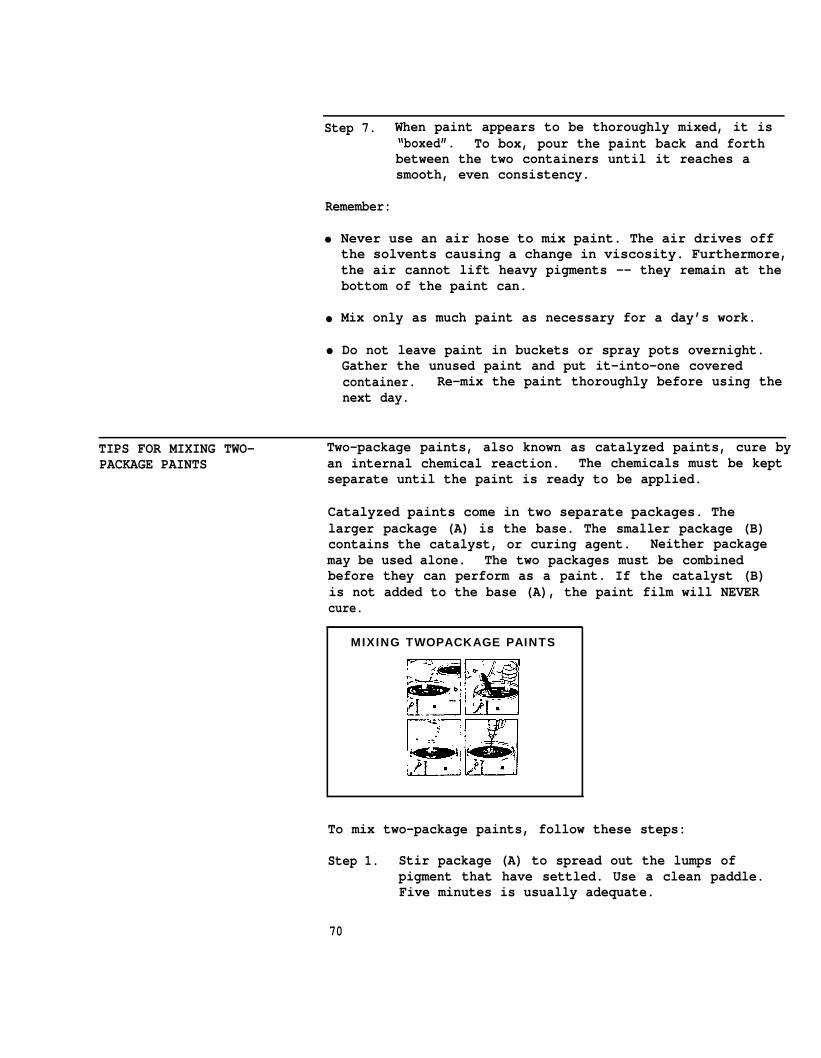
TIPS FOR MIXING TWO- Two-package paints, also known as catalyzed paints, cure byPACKAGE PAINTS an internal chemical reaction. The chemicals must be kept
separate until the paint is ready to be applied.
Catalyzed paints come in two separate packages. Thelarger package (A) is the base. The smaller package (B)contains the catalyst, or curing agent. Neither packagemay be used alone. The two packages must be combinedbefore they can perform as a paint. If the catalyst (B)is not added to the base (A), the paint film will NEVERcure.
MIXING TWOPACKAGE PAINTS
To mix two-package paints, follow these steps:
Step 1. Stir package (A) to spread out the lumps ofpigment that have settled. Use a clean paddle.Five minutes is usually adequate.
70

Step 2. While continuing to stir, slowly add all ofpackage (B).
Step 3. Agitate the two combined parts until they are asmooth, even consistency. Use either a manual ormotorized agitator.
As soon as the two packages have been combined, the chemicalreaction which leads to curing begins. The paint muststand for approximately 30 minutes before it is “set” andis ready to apply. This setting up, or “induction” time isa critical part of mixing two-package paints.
Once the two parts of a catalyzed paint are combined, thechemical reaction which leads to curing cannot be stopped.If paint is allowed to stand beyond its pot life, it willharden into a solid mass in the spray pot, lines, and guns.
Don’t waste paint:
• Mix only enough for prompt use. In typical productionspraying, 5 gallons will be sprayed in an hour. Mixsmaller batches just before lunch or at the end of ashift.
POT LIFE-
• Don’t leave paint in the lines and gun during lunch or awork stoppage. The hot sun will accelerate the curingtime and shorten the pot life. Hours will be wastedcleaning or replacing the equipment.
HOW DO YOU KNOW WHEN Take a sample of paint from the bottom of the containerPAINT IS MIXED and compare it with a sample taken from the top. If theTHOROUGHLY? paint is not mixed thoroughly enough, the paint from the
bottom will be thicker due to a higher pigment
concentration. When the paint appears to be consistentthroughout, it is properly mixed.
With all paints, straining should follow mixing to catchany remaining lumps.
HOW DOES TEMPERATURE AFFECT Temperatures of air, surface, or paint material that arePAINT APPLICATION? too high cut down the pot life of the paint. Temperatures
that are too low make the curing time longer.
Most paints should be applied at air temperatures between50-90 degrees F. Using conventional application methods,the best temperature range is 70-90 degrees F. Thetemperature of the material should be at least as high asthe surface to be coated. Follow manufacturer’sinstructions carefully.
WHY DOES THE DEW POINT Dew point is the temperature at which moisture condenses onDETERMINE WHEN PAINTING a surface. Especially in the morning, during changingCAN BEGIN? weather conditions, and during seasonal changes,
condensation is common. This produces a thin film ofmoisture on the steel which may be invisible to the nakedeye.
To avoid painting over moisture and causing drasticfailures, the dew point should be measured. Paintingshould not begin until the surface temperature of the steelis five degrees above the dew point.
This five degree rule is a common, good practice to allowfor errors in measurement and for temperature fluctuations.
72

PART C UNIT II
COMMON METHODS OF SHIPYARD PAINT APPLICATION
WHAT ARE COMMON METHODS • BrushingOF PAINT? • Rolling
Ž Spraying
Brushing works the paint into all the pores and dents of thesurface. Because it makes very close contact with themetal surface, brushing is a good method to use forapplying the first coat of paint, called the “primer”.Brush application is primarily used for touch-up jobs andin small areas, not for painting large areas.
Rolling can be used on large areas, such as decks and ininterior areas where over-spray presents a cleaning problem.Never use a roller to apply the primer; the paint will notpenetrate the surface well and will be applied over poresand dents. Rollers are used with good results after theprimer has been applied.
Spraying is widely used in shipyards for high production.It is a mechanical method of applying paint in which thepaint fluid is “atomized,” or broken into a fine spray ofsmall particles.
TIPS FOR PROPER The brush is an important tool in the painting trade.PAINT BRUSH USE Select good quality natural bristles or synthetic filaments
which will not be destroyed by “hot” solvents.
1.
2.
3.
4.
5.
6.
Shake loose any unattached bristles by spinning thebrush between your palms.
Snap off any stray bristles. A putty knife will helphere.
Dip the brush into the paint to cover 1/3 of the lengthof the bristles. Do not cover the entire bristlelength. The paint will fill the heel of the brush andrun down the handle and operator’s arm.
Remove excess paint by slapping the brush on the sideof the can.
Paint with the tips of the bristles. Use a light touch.Don’t press down hard on the bristles.
Always work from the dry to the wet surface. Do notpull the paint brush through wet paint to the unpaintedsurface.
73
d
7. Avoid brushing paint out too thin, leaving unprotecteda r e a s .
8. Always apply the second coat of paint at right anglesto the first.
9. Wash, shape, and dry the brush after each use for longlife.
Proper use of a paint brush will result in good coverageand a smooth finish with a minimum of effort.
TIPS FOR PROPER ROLLER USE For painting on steel, select a roller with a proper naplength. Be certain that the roller core will resist strongsolvents and the fiber will not loosen and stick to the coatesurface. A phenolic core is often recommended.
1. For thick-bodied coatings, dip the roller directlyinto the paint container. For thin-bodied coatings,dip the roller into a roller tray.
2. To apply the paint evenly, the roller must be properlyloaded. Skidding or tracking will occur if the rolleris too dry or is loaded with too much paint. Donot roll the paint out too thin -- the roller shouldhave enough material to provide a sufficient filmthickness.
3. Do not apply heavy pressure -- it is not necessary forgood film build and makes the work more difficult.
4. Apply the second coat at right angles to the first.
WHAT IS THE DIFFERENCE There are two spray methods: conventional and airless. TheyBETWEEN CONVENTIONAL AND differ mainly in the way the paint fluid is atomized. InAIRLESS SPRAY? a conventional spray gun, jets of compressed air are shot
into the paint stream at the nozzle. The paint isbroken up and carried to the surface on this air stream.In the airless method, the paint is forced through a verysmall opening at the nozzle under very high pressure. Itis broken into tiny particles as it is released from thenozzle.
74
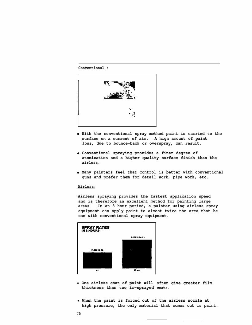
Conventional :
I
●
●
●
With the conventional spray method paint is carried to thesurface on a current of air. A high amount of paintloss, due to bounce-back or overspray, can result.
Conventional spraying provides a finer degree ofatomization and a higher quality surface finish than theairless.
Many painters feel that control is better with conventionalguns and prefer them for detail work, pipe work, etc.
Airless:
Airless spraying provides the fastest application speedand is therefore an excellent method for painting largeareas. In an 8 hour period, a painter using airless sprayequipment can apply paint to almost twice the area that hecan with conventional spray equipment.
• One airless coat of paint willthickness than two ir-sprayed
often give greater filmcoats.
• When the paint is forced out of the airless nozzle athigh pressure, the only material that comes out is paint.
75
Since no air mixes in with the paint fluid, there isvery little danger of moisture or dirt ruining the paintfinish.
• The high pressure also forces the paint into cavitiesand corners with little rebound from the surface.
HOW DOES SPRAY PAINTING Both conventional and airless spray are faster than brushCOMPARE TO OTHER METHODS or roller application.OF PAINTING APPLICATION?
Ž The paint supply comes through the gun -- there is noneed to dip a brush or roller into a paint container.
• The time it takes to paint a large area is greatlyreduced. A painter using a brush can apply paint to1,000 square feet in 8 hours. With airless sprayequipment, he can cover the same area in at least 1/8 thetime.
● Spray application provides a high, even film thicknessand good appearance in one coat at an increasedproduction rate.
76
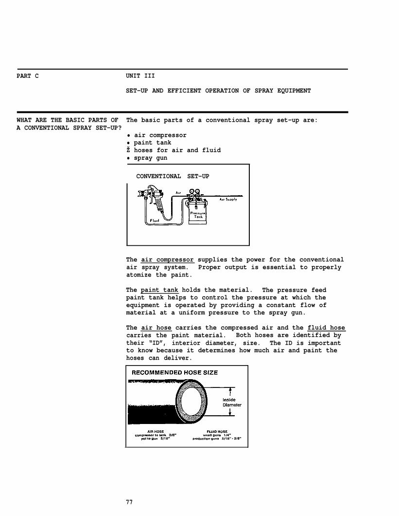
PART C UNIT III
SET-UP AND EFFICIENT OPERATION OF SPRAY EQUIPMENT
WHAT ARE THE BASIC PARTS OF The basic parts of a conventional spray set-up are:A CONVENTIONAL SPRAY SET-UP?
• air compressor• paint tankŽ hoses for air and fluid• spray gun
CONVENTIONAL SET-UP
The air compressor supplies the power for the conventionalair spray system. Proper output is essential to properlyatomize the paint.
The paint tank holds the material. The pressure feedpaint tank helps to control the pressure at which theequipment is operated by providing a constant flow ofmaterial at a uniform pressure to the spray gun.
The air hose carries the compressed air and the fluid hosecarries the paint material. Both hoses are identified bytheir “ID”, interior diameter, size. The ID is importantto know because it determines how much air and paint thehoses can deliver.
77
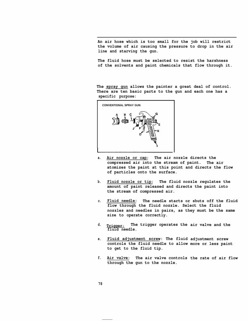
An air hose which is too small for the job will restrictthe volume of air causing the pressure to drop in the airline and starving the gun.
The fluid hose must be selected to resist the harshnessof the solvents and paint chemicals that flow through it.
The spray gun allows the painter a great deal of control.There are ten basic parts to the gun and each one has aspecific purpose:
CONVENTIONAL SPRAY GUN
a.
b.
c.
d.
e.
f.
Air nozzle or cap: The air nozzle directs thecompressed air into the stream of paint. The airatomizes the paint at this point and directs the flowof particles onto the surface.
Fluid nozzle or tip: The fluid nozzle regulates theamount of paint released and directs the paint intothe stream of compressed air.
Fluid needle: The needle starts or shuts off the fluidflow through the fluid nozzle. Select the fluidnozzles and needles in pairs, as they must be the samesize to operate correctly.
Trigger: The trigger operates thefluid needle.
Fluid adjustment screw: The fluidcontrols the fluid needle to allowto get to the fluid tip.
Air valve: The air valve controlsthrough the gun to the nozzle.
air valve and the
adjustment screwmore or less paint
the rate of air flow
78

g. Side port control: The side port control regulatesthe supply of air to the air nozzle and it determines the size and shape of the spray pattern.
h. Gun body and handle: The gun body is the part of theequipment the painter holds to operate the spray gun.
i. Air inlet: The air inlet is at the bottom of thehandle and is connected to the air hose.
j . Fluid inlet: The fluid inlet is an opening below thefluid needle and is connected to the fluid hose.
SETTING UP CONVENTIONAL With a pressure tank system, the setting up procedure is asSPRAY EQUIPMENT follows:
1.
2.
3.
4.
5.
6.
7.
8.
Attach the air hose from the compressor tank, or controldevice such as an air transformer, to the air inlet onthe pressure tank lid. Connect the atomizing air hoseand paint hose to the spray gun. Tighten allconnections with a hose wrench. Do not use pliers orpipe wrenches.
Open the relief valve on the tank. Keep valves to tankand hose closed.
Fill tank or removable tank liner with paint.
Fasten lid to tank. Tighten clamps.
Close relief valve.
Start the compressor.
Open the valve to the tank but not to the atomizing airhose.
Open the air spreader and fluid adjusting valves on thespray gun.
79
At this point, you must decide what pressures to use for thejob. Use the manufacturer’s instructions as a guide anddetermine the pressure settings as follows:
1.
2.
3.
4.
Remove the air cap from the gun.
Trigger the gun and increase the fluid pressure untila stream of paint shoots out about three feet beforeit begins to fall into a pail on the floor. Releasethe trigger.
Replace the air cap and set the air pressure somewhatbelow the recommended setting. Test the spray pattern.Increase the air pressure by five pounds at a timeuntil you obtain the best atomization.
Spray a small area of surface. If the paint seems toodry, reduce the air pressure or increase the paint tankpressure until the test spray pattern and finish isjust right. Do whichever adjustment will come closestto the manufacturer’s specifications.
WHAT IS THE PROCEDURE FOR Follow this checklist for the basic procedure, but alwaysSHUTDOWN OF CONVENTIONAL read the manufacturer’s instructions for the actualEQUIPMENT? equipment being used.
1.
2.
3.
4.
Close air inlet valve to the tank. Leave atomizing airto gun turned on.
Open relief valve on the pressure tank. This willrepressurize the tank.
Open the tank lid carefully.
Loosen the air cap on the gun about a half turn. Holda wadded cloth over the cap and trigger the gun. Thiswill force any paint in the gun and hose back to thetank. CAUTION: This operation called “blow-back”,can only be used with conventional air spray. It mustnever be used with the airless spray paintingequipment.
80
5. Remove paint from the tank. Clean the insert orinterior of the tank by pouring a small amount ofsolvent into the container.
6. Pour enough solvent into the tank to also wash theinterior of the spray gun and hose.
7. Trigger the gun and allow the solvent to run through thegun until the solvent comes out free of paint particles.Repeat the blow-back procedures.
HOW TO CORRECT FAULTY The ideal spray pattern with a conventional gun is a longAIR SPRAY PATTERNS oval with clear edges. Experience will help you observe
the spray pattern to be able to adjust the gun andcorrect faulty shapes.
Following are some of the most common air spray patternproblems and how to correct them.
A. “Boomerang” pattern.
Cause: Dried paint in one of the side port holes ofthe air nozzle. At full pressure, the airand paint exit from the clean side port.
Remedy: Dissolve the dried paint with thinner. Do notuse metal devices to probe into the airnozzle openings.
B. Larger at one end.
Cause: 1)
2)
Remedy: 1)
2)
Dried paint around the outside of the fluid tip, restricting the passage of atomizingair.
Loose air nozzle; also bent fluid nozzleor needle tip.
Remove air nozzle and wipe off the fluidtip with thinner.
Tighten the air nozzle and replace any bentparts.
81
C. Hour glass pattern.
Cause: 1) Air pressure is too high.
2) Not enough paint; fluid pressure is too low.
3) Too wide a pattern with thin paint.
Remedy: 1) Reduce the air pressure.
2) Increase fluid supply.
3) Adjust pattern control knob.
D. Heavy middle.
Cause: 1) Air pressure too low.
2) Too much fluid fed to the gun.
Remedy: 1) Increase air pressure.
2) Decrease fluid pressure or use a smllfluid nozzle orifice.
E. Fluid spitting ; air entering fluid supply.
Cause: 1) Dried or missing packing around the flneedle valve.
2) Dirty fluid nozzle seat.
er
ui d
3) Loose fluid nozzle, packing nut, fluid hose.
Remedy: 1) Clean packing with light machine oil.Replace if necessary.
2) Clean fluid nozzle seat area with thinner.
3) Tighten connections and fittings.
82
WHAT ARE THE BASIC PARTS The three basic parts of airless spray equipment are:OF AN AIRLESS SPRAY SYSTEM?
Ž high pressure paint pump• paint hoseŽ airless spray gun
The high pressure pump draws the paint from the containerand forces it through the paint hose and spray gun.
The paint hose must be able to stand very high pressure asit carries the paint from the pump to the gun. Mostpainters will require only 1800 psi to 3500 psi, but mostairless hoses can handle pressure of up to 5000 psi. Thehoses range in size to accommodate paints which havedifferent viscosities.
The spray gun is basically a fluid nozzle and a valve. Itis a passageway for different types of paint and spraypatterns. There is a spray tip filter which screens outlarge particles of paint that could clog the tip. Eachspray tip is designed to give a specific spray patternand flow. There is only one hose -- the high pressurepaint hose -- connected to the gun.
HOW IS THE AIRLESS The basic procedure for airless equipment set-up is asEQUIPMENT SET-UP? follows. Read the manufacturer’s instructions for
specifics regarding the type of equipment in use.
1.
2.
3.
4.
Connect air supply hose between air inlet on the pumpand the air supply.
Connect the high pressure fluid hose between filtermanifold (or pump outlet) and the spray gun.
Make certain that the regulator adjustment is backedoff, then open the main air supply valve to theregulator.
Immerse fluid pump or siphon hose in container orsuitable solvent.
83
5.
6.
7.
8.
9.
10.
11.
12.
13.
14.
15.
16.
17.
Turn air regulator adjustment until pump begins tooperate slowly.
Direct spray gun into solvent container and pulltrigger.
Increase air regulator and run pump for approximately30 seconds at a moderate speed. Back-off regulatoruntil pump stops.
Check all hose connections for leaks.
Remove siphon hose or fluid pump from solvent.
Open regulator and allow system to pump out solvent.
Allow air to flow through system for about 30 seconds.
Check agitator and other air operated accessories forproper functioning.
Shut off air inlet.
Strain paint and other similar fluids before fillingreservoir.
Fill the fluid reservoir.
Immerse siphon hose or pump in fluid.
Select proper tip.
HOW IS AIRLESS After use, these procedures should be followed forEQUIPMENT SHUT DOWN? shutting down the airless spray equipment.
1.
2.
3.
Shut off air to pump by closing the air supplyvalve.
Decrease air pressure regulator.
Release fluid pressure by placing gun below materialin the fluid reservoir and pulling trigger untilfluid ceases to flow or by opening by-pass valve if soequipped.
84
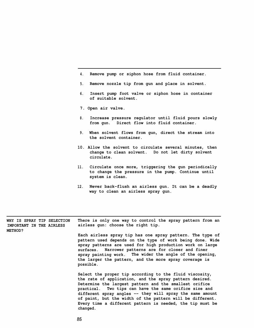
4. Remove pump or siphon hose from fluid container.
5. Remove nozzle tip from gun and place in solvent.
6. Insert pump foot valve or siphon hose in containerof suitable solvent.
7. Open air valve.
8. Increase pressure regulator until fluid pours slowlyfrom gun. Direct flow into fluid container.
9. When solvent flows from gun, direct the stream intothe solvent container.
10. Allow the solvent to circulate several minutes, thenchange to clean solvent. Do not let dirty solventcirculate.
11. Circulate once more, triggering the gun periodicallyto change the pressure in the pump. Continue untilsystem is clean.
12. Never back-flush an airless gun. It can be a deadlyway to clean an airless spray gun.
WHY IS SPRAY TIP SELECTION There is only one way to control the spray pattern from anIMPORTANT IN THE AIRLESS airless gun: choose the right tip.METHOD?
Each airless spray tip has one spray pattern. The type ofpattern used depends on the type of work being done. Widespray patterns are used for high production work on largesurfaces. Narrower patterns are for closer and finerspray painting work. The wider the angle of the opening,the larger the pattern, and the more spray coverage ispossible.
Select the proper tip according to the fluid viscosity,the rate of application, and the spray pattern desired.Determine the largest pattern and the smallest orificepractical. Two tips can have the same orifice size anddifferent spray angles -- they will spray the same amountof paint, but the width of the pattern will be different.Every time a different pattern is needed, the tip must bechanged.
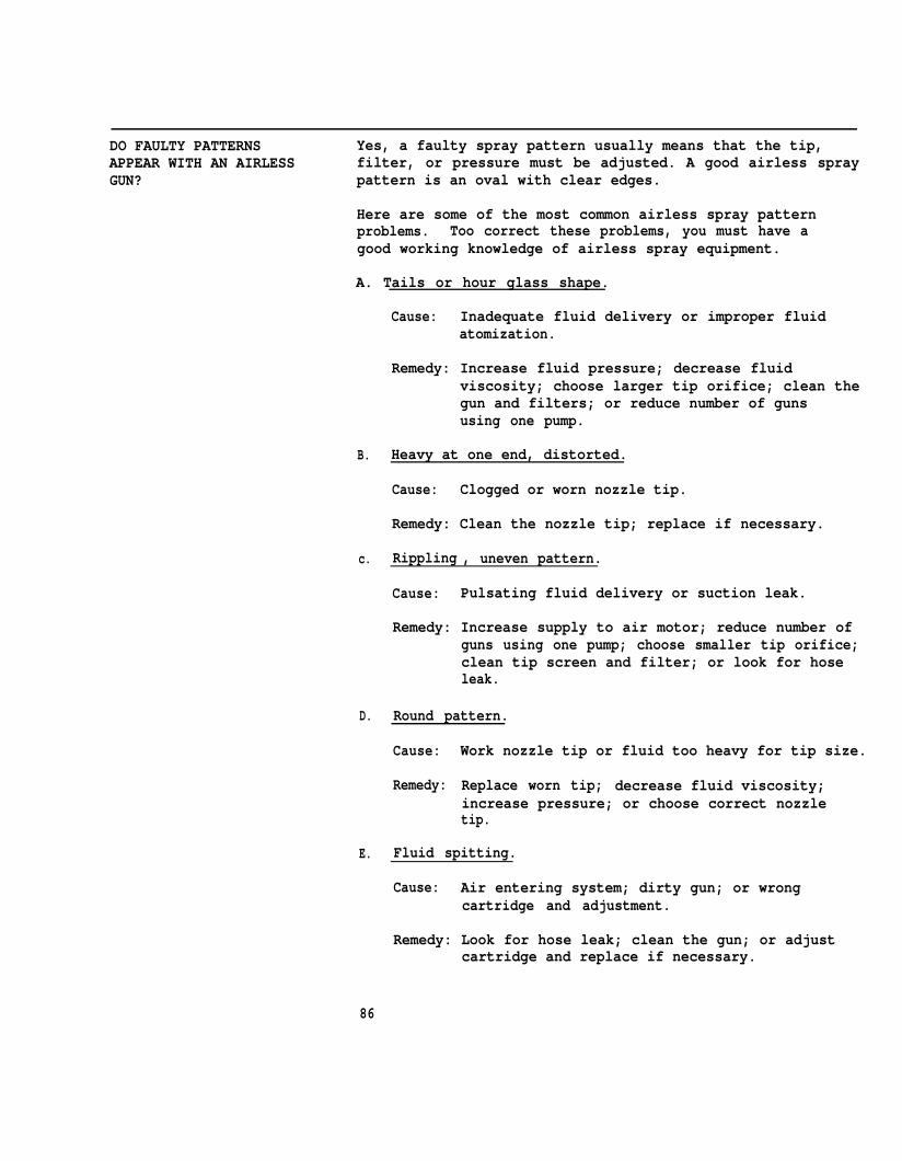
DO FAULTY PATTERNS Yes, a faulty spray pattern usually means that the tip,APPEAR WITH AN AIRLESS filter, or pressure must be adjusted. A good airless sprayGUN? pattern is an oval with clear edges.
Here are some of the most common airless spray patternproblems. Too correct these problems, you must have agood working knowledge of airless spray equipment.
A. Tails or hour glass shape.
Cause: Inadequate fluid delivery or improper fluidatomization.
Remedy: Increase fluid pressure; decrease fluidviscosity; choose larger tip orifice; clean thegun and filters; or reduce number of gunsusing one pump.
B. Heavy at one end, distorted.
Cause: Clogged or worn nozzle tip.
Remedy: Clean the nozzle tip; replace if necessary.
c. Rippling , uneven pattern.
Cause: Pulsating fluid delivery or suction leak.
Remedy: Increase supply to air motor; reduce number ofguns using one pump; choose smaller tip orifice;clean tip screen and filter; or look for hoseleak.
D. Round pattern.
Cause:
Remedy:
Work nozzle tip or fluid too heavy for tip size.
Replace worn tip; decrease fluid viscosity;increase pressure; or choose correct nozzletip.
E. Fluid spitting.
Cause: Air entering system; dirty gun; or wrongcartridge and adjustment.
Remedy: Look for hose leak; clean the gun; or adjustcartridge and replace if necessary.
86
LEANING AND LUBRICATING Most spray painting problems a painter experiences areA SPRAY GUN directly related to improper or inadequate cleaning of
spray guns. Both conventional and airless spray gunsshould be thought of as precision tools and they shouldbe cared for as such. They must be kept lubricated andclean.
Follow these rules for keeping an air spray gun in its bestworking order:
Ž Never soak the whole gun in solvent. Solvents removelubricants and dry out the gun packings. Dirt cancollect in the air passages and can later mix with thepaint and be sprayed onto the surface.
● Lubricate the air spray gun every day with a drop oflight machine oil to keep the parts moving easily. Thepoints that need lubrication are the:
a. trigger pivot,b. fluid packing nut,c. air valve packing,d. fluid needle spring, ande. side port and control knobs.
• Wash the gun body with a rag dipped in solvent. TO cleanother exterior surfaces, only the front end of the gunis put into solvent. A non-wire brush should be usedto remove any paint that has dried on the surface.
To unclog the airin clean solvent.match can be usedsharp instrumentsnozzle and should
Never use oils or
nozzle, remove and wash it separatelyA pipe cleaner, a broom bristle, or a
to clean the holes. Wire or othermay cause permanent damage to thenever be used.
lubricants containing silicones.
87

With an airless spray gun, the most common operatingproblem is due to the tip getting clogged. All airlessequipment should be flushed with solvent after each use.The fluid hose should be cleaned as well. The most commoncause of clogging is dried paint flaking off the innerwalls of a used paint hose. To clean the airless tip:
Ž Relieve fluid pressure
Ž Rotate trigger release to safe position
• Remove cap, nozzle tip and gasket
ŽFlush nozzle tip with solvent
• Blow air through tip and look for blockage
88

PART C UNIT IV
GOOD SPRAYING PRACTICES
WHAT IS A GOOD TECHNIQUE Proper stroking technique is essential to good sprayIN USING A SPRAY GUN? painting. Poor techniques can use excessive material
and the personal energy of the painter. Basically, thesame techniques are used with conventional and airlessspraying. The following rules are basics and should beused in both methods of spray painting.
Stroking
● While holding the spray gun at the proper angle, move thearm and shoulder as well as the wrist to prevent “arcing”which Qives an uneven coat. The arm MUST remain atright angles to the surface.
89
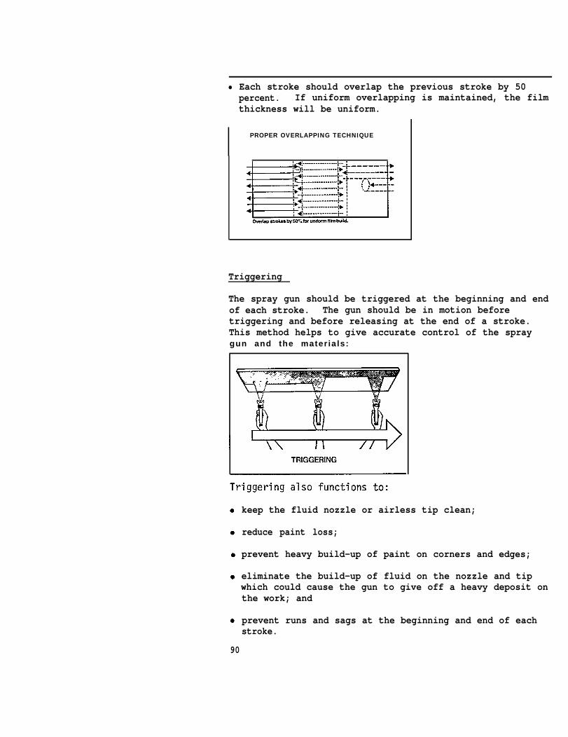
• Each stroke should overlap the previous stroke by 50percent. If uniform overlapping is maintained, the filmthickness will be uniform.
PROPER OVERLAPPING TECHNIQUE
Triggering
The spray gun should be triggered at the beginning and endof each stroke. The gun should be in motion beforetriggering and before releasing at the end of a stroke.This method helps to give accurate control of the spraygun and the mater ia ls:
keep the fluid nozzle or airless tip clean;
reduce paint loss;
prevent heavy build-up of paint on corners and edges;
eliminate the build-up of fluid on the nozzle and tipwhich could cause the gun to give off a heavy deposit onthe work; and
prevent runs and sags at the beginning and end of eachstroke.
90
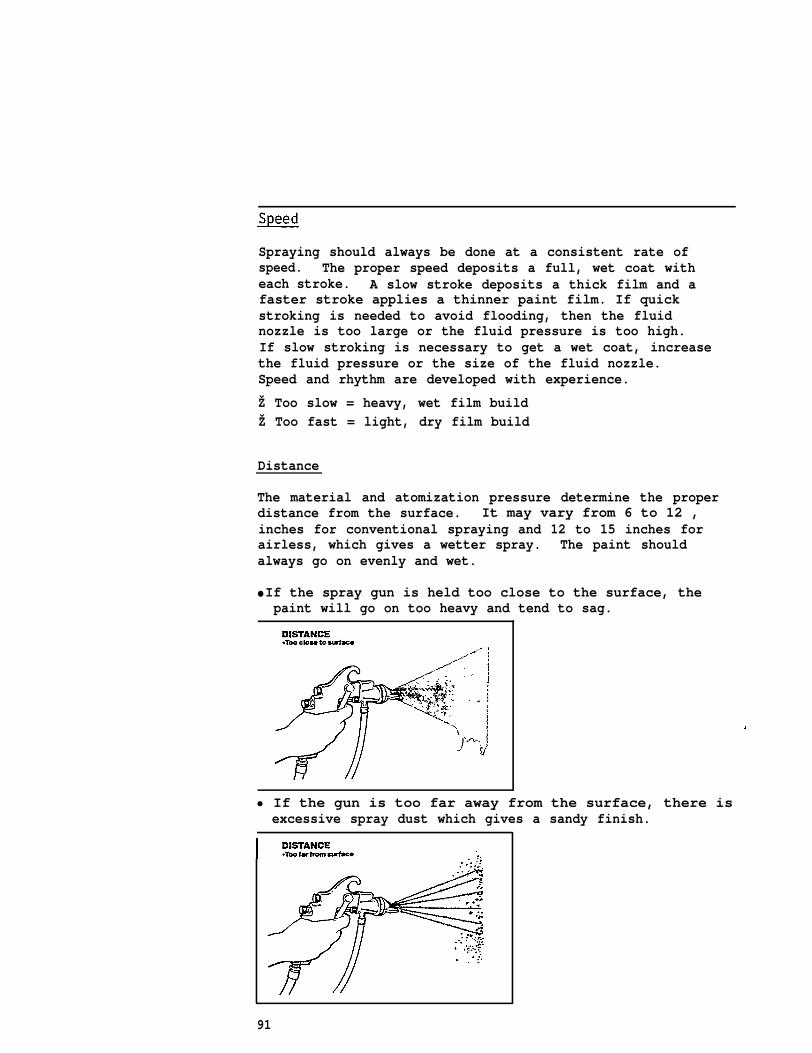
Spraying should always be done at a consistent rate ofspeed. The proper speed deposits a full, wet coat witheach stroke. A slow stroke deposits a thick film and afaster stroke applies a thinner paint film. If quickstroking is needed to avoid flooding, then the fluidnozzle is too large or the fluid pressure is too high.If slow stroking is necessary to get a wet coat, increasethe fluid pressure or the size of the fluid nozzle.Speed and rhythm are developed with experience.
Ž Too slow = heavy, wet film buildŽ Too fast = light, dry film build
Distance
The material and atomization pressure determine the properdistance from the surface. It may vary from 6 to 12 ,inches for conventional spraying and 12 to 15 inches forairless, which gives a wetter spray. The paint shouldalways go on evenly and wet.
● If the spray gun is held too close to the surface, thepaint will go on too heavy and tend to sag.
• If the gun is too far away from the surface, there is excessive spray dust which gives a sandy finish.
91
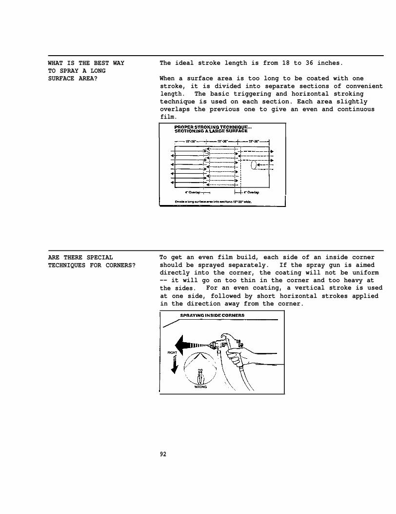
WHAT IS THE BEST WAY The ideal stroke length is from 18 to 36 inches.TO SPRAY A LONGSURFACE AREA? When a surface area is too long to be coated with one
stroke, it is divided into separate sections of convenientlength. The basic triggering and horizontal strokingtechnique is used on each section. Each area slightlyoverlaps the previous one to give an even and continuousfilm.
ARE THERE SPECIAL To get an even film build, each side of an inside cornerTECHNIQUES FOR CORNERS? should be sprayed separately. If the spray gun is aimed
directly into the corner, the coating will not be uniform-- it will go on too thin in the corner and too heavy atthe sides. For an even coating, a vertical stroke is usedat one side, followed by short horizontal strokes appliedin the direction away from the corner.
92
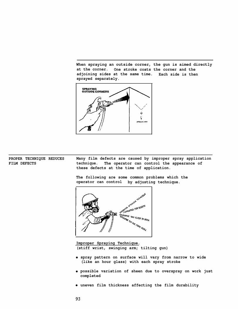
When spraying an outside corner, the gun is aimed directlyat the corner. One stroke coats the corner and theadjoining sides at the same time. Each side is thensprayed separately.
PROPER TECHNIQUE REDUCES Many film defects are caused by improper spray applicationFILM DEFECTS technique. The operator can control the appearance of
these defects at the time of application.
The following are some common problems which theoperator can control by adjusting technique.
Improper Spraying Technique.(stiff wrist, swinging arm; tilting gun)
●
●
●
spray pattern on surface will vary from narrow to wide(like an hour glass) with each spray stroke
possible variation of sheen due to overspray on work justcompleted
uneven film thickness affecting the film durability

Improper Fan Width.
Ž inadequate film build in the angle vertex or fillet of“I” and “H” beams when a painter uses a wide fan andsprays at a 45° angle from the flange into the corner.An excessive film build in the web and flange may alsooccur
Ž inadequate film build on bar joists when too wide fanis used
Spray Operator Too Close to His Work.
Ž excessive film build
Ž runs, curtains, sags
Ž poor film adhesion due to improper drying and curing
• high film build; wrinkles while drying and may holdcontaminants
• excessive paint used
Ž orange peel pattern and blow holes
Spray Operator Too Far Back from His Work.
• film build too thin
Ž uneven film build
● dry spray: the film is permeable
• uneven angular sheen due to overspray on finished work
● overspray deposits on unprotected substrate
• excessive paint used
94
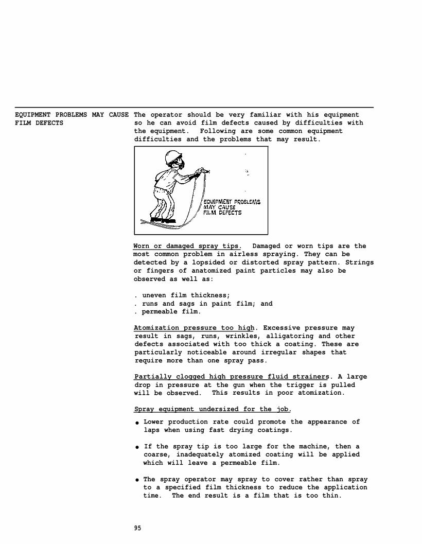
EQUIPMENT PROBLEMS MAY CAUSE The operator should be very familiar with his equipmentFILM DEFECTS so he can avoid film defects caused by difficulties with
the equipment. Following are some common equipmentdifficulties and the problems that may result.
Worn or damaged spray tips. Damaged or worn tips are themost common problem in airless spraying. They can bedetected by a lopsided or distorted spray pattern. Stringsor fingers of anatomized paint particles may also beobserved as well as:
. uneven film thickness;
. runs and sags in paint film; and
. permeable film.
Atomization pressure too high. Excessive pressure mayresult in sags, runs, wrinkles, alligatoring and otherdefects associated with too thick a coating. These areparticularly noticeable around irregular shapes thatrequire more than one spray pass.
Partially clogged high pressure fluid strainers. A largedrop in pressure at the gun when the trigger is pulledwill be observed. This results in poor atomization.
Spray equipment undersized for the job.
●
●
●
Lower production rate could promote the appearance oflaps when using fast drying coatings.
If the spray tip is too large for the machine, then acoarse, inadequately atomized coating will be appliedwhich will leave a permeable film.
The spray operator may spray to cover rather than sprayto a specified film thickness to reduce the applicationtime. The end result is a film that is too thin.
95
Paint hoses too long or too small in diameter.
Ž A coarse inadequately atomized coating will leave apebbly appearance.
Ž The film will have thin spots affecting durability.
Air supply hoses too small or too long.
• The paint pump cannot maintain constant pressure.
Ž The spray pattern will show inadequate atomization in theform of a coarse and pebbly texture and strings andfingers coming from the spray gun.
Ž Pulsation of the spray pattern, changing size of theatomized paint particles, and fluctuation of the sprayfan width delivers an uneven film thickness and mayaffect film durability.
96
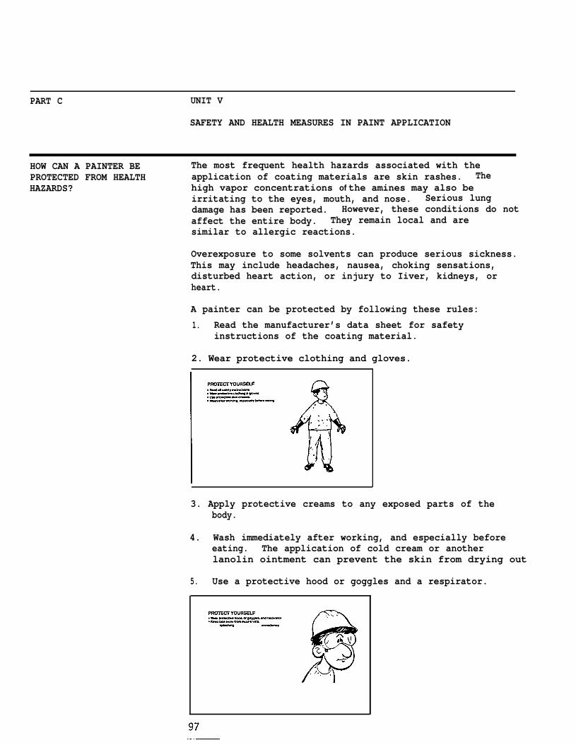
PART C UNIT V
SAFETY AND HEALTH MEASURES IN PAINT APPLICATION
HOW CAN A PAINTER BE The most frequent health hazards associated with thePROTECTED FROM HEALTH application of coating materials are skin rashes. TheHAZARDS? high vapor concentrations of the amines may also be
irritating to the eyes, mouth, and nose. Serious lungdamage has been reported. However, these conditions do notaffect the entire body. They remain local and aresimilar to allergic reactions.
Overexposure to some solvents can produce serious sickness.This may include headaches, nausea, choking sensations,disturbed heart action, or injury to Iiver, kidneys, orheart.
A painter can be protected by following these rules:
1. Read the manufacturer’s data sheet for safetyinstructions of the coating material.
2. Wear protective clothing and gloves.
3. Apply protective creams to any exposed parts of thebody.
4. Wash immediately after working, and especially beforeeating. The application of cold cream or anotherlanolin ointment can prevent the skin from drying out
5. Use a protective hood or goggles and a respirator.
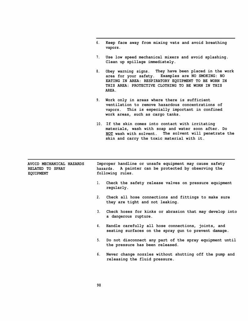
6.
7.
8.
9.
10.
Keep face away from mixing vats and avoid breathingvapors.
Use low speed mechanical mixers and avoid splashing.Clean up spillage immediately.
Obey warning signs. They have been placed in the workarea for your safety. Examples are NO SMOKING: NOEATING IN AREA: RESPIRATORY EQUIPMENT TO BE WORN INTHIS AREA: PROTECTIVE CLOTHING TO BE WORN IN THISAREA.
Work only in areas where there is sufficientventilation to remove hazardous concentrations ofvapors. This is especially important in confinedwork areas, such as cargo tanks.
If the skin comes into contact with irritatingmaterials, wash with soap and water soon after. DoNOT wash with solvent. The solvent will penetrate theskin and carry the toxic material with it.
AVOID MECHANICAL HAZARDS Improper handline or unsafe equipment may cause safetyRELATED TO SPRAY hazards. A painter can be protected by observing theEQUIPMENT following rules.
1.
2.
3.
4.
5.
6.
Check the safety release valves on pressure equipmentregularly.
Check all hose connections and fittings to make surethey are tight and not leaking.
Check hoses for kinks or abrasion that may develop intoa dangerous rupture.
Handle carefully all hose connections, joints, andseating surfaces on the spray gun to prevent damage.
Do not disconnect any part of the spray equipment untilthe pressure has been released.
Never change nozzles without shutting off the pump andreleasing the fluid pressure.
98
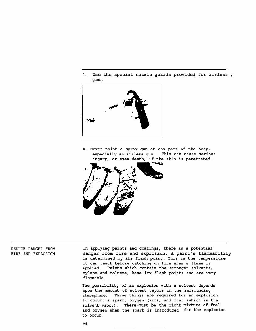
7. Use the special nozzle guards provided for airless ,guns.
8. Never point a spray gun at any part of the body,especially an airless gun. This can cause seriousinjury, or even death, if the skin is penetrated.
REDUCE DANGER FROM In applying paints and coatings, there is a potentialFIRE AND EXPLOSION danger from fire and explosion. A paint’s flammability
is determined by its flash point. This is the temperatureit can reach before catching on fire when a flame isapplied. Paints which contain the stronger solvents,xylene and toluene, have low flash points and are veryflammable.
The possibility of an explosion with a solvent dependsupon the amount of solvent vapors in the surroundingatmosphere. Three things are required for an explosionto occur: a spark, oxygen (air), and fuel (which is thesolvent vapor). There-must be the rightand oxygen when the spark is introducedto occur.
mixture of fuelfor the explosion
99
If there is too much fuel in the mixture, thereis not enough oxygen present for an explosion. If thereis too little fuel present, it means there is not enoughfor an explosion to occur.
Follow these safety rules when handling flammable paintmaterials.
●
●
●
Avoid storing or using paint in an area with atemperature that is near or above the flash point.
Spray units and their components must be grounded toprevent dangerous static sparking. Make sure theelectric supply circuit is grounded as well. If sprayingwith a flammable material, the object being painted aswell as the spray gun must be grounded to prevent staticelectricity from causing a spark.
Do not spray solvent under pressure through the gunnozzle tip.- An explosion or fire could result fromstatic electricity build-up in the presence of flammablevapors. Always remove the nozzle tip from the gun beforecleaning.
Ž Never smoke while mixing or applying paint. All sourcesof flame must be removed from the area where paints aremixed or applied. Extinguish all pilot lights on waterheaters, furnaces, or other equipment in the area.Welding should not be permitted in the same area.
• In confined areas, use onlyproof electrical equipment.
• Do not work in an area whenof excessive solvent odor.
Ž Mix all materialssparks and flame.
n a well
vapor-proof and explosion-
the air is not clear and free
venti ated area, away from
100
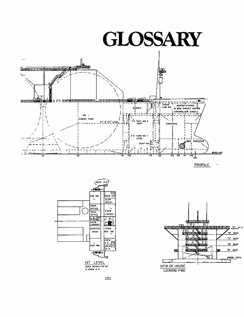
101
GLOSSARY
ABRASION
ABRASIONRESISTANCE
ABRASIVE
ADHESION
AGITATE
AIRCOMPRESSOR
ALKALI
AMBIENTTEMPERATURE
ANCHOR PATTERN
ANTIFOULING
ATOMIZE
BINDER
BLAST PATTERN
BONDING
BOUNCE-BACK
BOXING
being worn away by rubbing or friction
resistance to being worn away by rubbing or friction;related to toughness, rather than the hardness of a paint film
the material used for abrasive blast cleaning, such as sand,mineral grit, steel shot or steel grit
bonding strength; the attraction of a coating to the surfaceto which it is applied
to stir or shake
a separate piece of equipment in spray systems which draws inair and compresses it, thus providing high pressure and volumeof air required for abrasive blasting and spray painting
a substance such as lye, soda, or lime that can be highlydestructive to paint films; caustic
room temperature or temperature of surrounds
a rough pattern of peaks and valleys caused by abrasive blastingwhich improves the ability of the paint to bond to the steel surface
coating containing toxic ingredients, such as cuprious oxide,applied to shipbottoms to prevent marine growth
to reduce a liquid to a mist; to break a stream of paint intosmall particles
the resin, or film-forming ingredient in paint, that binds thepigment particles together
the surface area hit by the abrasives: the closer the nozzle isheld to the surface, the smaller the blast pattern
a mechanical attraction between two surfaces, such as two coats ofpaint or paint and a substrate; the mechanical “holding effect”between paint and steel, for example, may be increased by rougheningthe steel surface
spray paint rebound from the surface
manual mixing of paint by pouring backto the other
and forth from one container
102
BREAKDOWN the extent to which an abrasive pellet is damaged after striking theCHARACTERISTICS work surface; related to the recyclability of an abrasive and degree
of dusting
BRONCHITIS an inflammation of the mucous lining of the bronchial tubes
BURNISH to make shiny by rubbing or polishing; burnished metal is a poorsurface for paint bonding
BURR a raised “splinter” on a metal surface which will interfere withcoating performance
CAMOUFLAGE
CATALYST
CFM
CHALKING
COBWEBBING
CONDENSATION
CONTAMINANT
CORROSION
CURING
the process of disguising or changing the appearance of a ship toblend into the background
curing agent; hardener
cubic feet per minute;compressor is measured
loss of gloss; powderypaint films
the capacity, or the air VOlin CFM units
surface, usually due to the
ume, of an air
weathering of
a stringy thin spray pattern; this paint film defect is frequentlyseen in hot weather when a fast solvent is used in chlorinatedrubber or vinyl paints; the solvent evaporates before the paintis deposited resulting in “fingers” or “cobwebs” of paint beingdelivered to the surface
to become more dense, as a vapor into a liquid; moisture may appearon a surface as an almost invisible film or as water
dirt, oil, grease, loose rust, paint, or mill scale, which must beremoved from the surface for paint to bond securely
gradual destruction of a material, such as metal, due to interactionwith the environment
hardening; setting up
DEADMAN VALVE
DEFECT
shut-off valve at the blast nozzle, which allows the blaster tostart or stop the abrasive flow
imperfections in the paint film which can lead to early paint failure
103
DEHYDRATION
DERMATITIS
DETERIORATION
DEW POINT
DISPERSE
DRY TO HANDLE
DRY TO RECOAT
EROSION
EVAPORATION
loss of moisture or fluid; to dry out
skin irritation or rash
the gradual decay of a material; as a paint film ages with exposureto sun, rain, and chemicals, its protective qualities deteriorateand corrosion can begin
temperature at which moisture condenses
to break up and distribute in different directions; in mixing apaint, the pigment must be evenly distributed
time interval between application and ability to touch a paintedsurface without damage
time interval between application and ability to receive next coatsatisfactorily
wearing away of a surface; heavy chalking tends to accelerateerosion of a paint film; water flow over a ship’s propeller causesmeta l e ros ion
the release of solvents from the paint f luid into the atmosphere
FAILURE loss of adhesive and/or protective qualities of a paint film whichcan no longer serve its function as a barrier to corrosion
FILM THICKNESS depth of applied coating, usually expressed in roils (metric: microns)
FLAMMABILITY ability to burn
FLASH POINT the lowest temperature at which a flammable material will igniteif a flame or spark is present
FOULING growth of attachments, such as weeds or barnacles, to hulls of shipsor other marine structures
FRICTION the rubbing of one object against another
104
GENERIC
GLOSS
GROUNDING
HORSEPOWER
HYPODERMICNEEDLE GUAGE
HYDROBLASTING
IMMERSION
IMPACT
IMPERMEABLE
INDUCTION TIME
INTERIORDIAMETER (ID)
IRON OXIDE
MIL
MILL SCALE
MISTCOAT
a class or group; generic paint types take their name from the kindof resin in the formulation -- alkyd, epoxy, etc.
ability to reflect; shininess; luster; brightness
dissipation of electrostatic charge
a unit for measuring the power of motors or engines(equal to a rate of 33,000 foot-pounds per minute); abbreviated HP
a guage inserted into the blast hose close to the nozzle to measureair pressure at the nozzle
water blasting; the use of water pumped at extremely high pressuresto remove unwanted materials from a surface
completely covered by water; submerged
striking together; collision
not permitting the passage or penetration of moisture, air orother substance
the length of time that a mixed catalyzed paint must stand beforeit is ready to apply (also called “setting up” or “sweating in” time)
measurement across the inside width of a hose, usually expressed ininches
a combination of iron (Fe) and oxygen (02); “rust” is a form ofiron oxide
one one-thousandth of an inch; .001”; 1/1000 inch
layer of iron oxide, bluish in appearance, formed on the surfaceof steel during manufacture
a heavily thinned coat of paint (approximately 90% solvent) appliedin a thin film (approximately .5 mil) to “re-flow” the previouscoat of paint; also used on porous films such as inorganic zinc toseal pores for topcoating
105
ORIFICE
OVERSPRAY
PASS
PEEN
PERMEABLE
PIGMENT
POTABLE WATER
POT LIFE
PRIMER
PROFILE
PSI
PSYCHROMETER
opening or hole, as in a spray gun fluid tip
fluid that is lost by missing the surface to be painted
motion of the spray gun in one direction only; one stroke
to hit the surface leaving rounded indentations, providing a waveyanchor pattern
allowing passage
paint ingredientprotection
drinkable water
or penetration
used mainly to impart color, hiding power, and
the time after the catalyzed paint has been mixed during which thematerial is usable
the first of two or more coats of a paint system; usually a rust-in-hibitive coating when used over ferrous metal
surface contour of a blast-cleaned surface as viewed from the edge;improves the ability of the paint to bond to the surface
pounds per square inch; a measure of force, such as the air pressureat the blast nozzle
an instrument with wet and dry bulb thermometers for measuring theamount of moisture in the air
RESIN a major ingredient of paint which binds the other ingredientstogether and imparts protective properties
RESPIRATOR a device worn over the mouth and nose to prevent inhaling harmfulsubstances such as dust, solvent vapors, fumes, etc.; respiratorsmay be cartridge, filter, or air-fed
106
SHELF LIFE
SILICOSIS
SKIDDING
SOLVENT
SPRAY FAN
SPRAY PATTERN
SUBSTRATE
SURFACEPREPARATION
THINNER
THIXOTROPIC
TOOTH
T O X I C
TIECOATING
VEHICLE
VENTURI NOZZLE
VISCOSITY
VOLUME SOLIDS
WELD FLUX
WELD SPLATTER
maximum amount of time in which a material may be stored and remainin usable condition
a type of respiratory disease caused by silica particles lodged in the1ungs
a paint roller sliding across a surface leaving roller tracks;caused by too little or too much paint on the roller cover
liquid ingredient of paint, the function of which is to dissolvethe resin so that it may be applied easily
shape of the spray pattern
description of the shape and size of the paint mist when itstrikes the surface; varies from a circle to a long narrow oval
surface to be painted
all operations necessary to prepare a surface to receive a coatingof paint
liquid added to a coating to adjust consistency
a gel which becomes a liquid when stirred but gels again on standing;“false-bodied”
surface roughness which improves the ability of the paint to bondto the surface
poisonous
application ofcoats of paint
a thin adhesive coat to aid in the bonding of two
liquid portion of a coating; made up of binder and solvent
nozzle with a tapered lining shape; it increases abrasive speed andcreates a larger, more even blast pattern
a measure of how fast or how slow a liquid flows
the percentage of the total volume occupied by non-volatiles(paint solids)
deposits of the fluxing (flowing) agent which, when left on themetal around a weld seam, may cause paint adhesion problems
beads of metal scattered next to the weld seam; these interferewith paint adhesion and should be removed
107
