at_pid
TRANSCRIPT

��������
����� ����
��������� ����
������� � ��������������� ��� ����
�������������
� � � � � � � � � � � � � � � � � � � � � � � � � �
FU b c Y _ ^ !& �
REBIS
1600 RIVIERA AVENUE., SUITE 300
WALNUT CREEK, CALIFORNIA 94596 USA
PHONE (925) 933-2525FAX (925) 933-1920WEB: WWW.REBIS.COM
�������

3?@IB978D 9>6?B=1D9?>
�G>5BC89@
Rebis documentation is copyrighted material. Reproduction of this material in any manner, inwhole or in part, is strictly forbidden by Rebis. ALL rights reserved.
�?D935
Rebis reserves the right to update, revise, and make changes to this product at the discretion ofRebis without any obligation on the part of Rebis. This information herein is subject to changewithout notice.
�9C3<19=5B
Although Rebis’ programs have been tested and appear to produce satisfactory results, no warrantyis expressed or implied, by the authors or by Rebis, as to the accuracy or functioning of theprogram, and no responsibility is assumed in connection therewith. All information presented is forreview, interpretation, approval, and application by authorized personnel.
�B145=1B;C
AutoPLANT®, PRO-SERIES®, and PlantLIFE® are registered trademarks of Rebis Inc.
AutoCAD® is a registered trademark in the U.S. Patent and Trademark Office by AutoDESK, Inc.
Windows®, MS-DOS®, Access®, Excel®, FoxPro®, and Lotus 1-2-3® are registered trademarks oftheir respective owners.
QA - IP160000
��������������
CHAPTER 1: INTRODUCTION
WHAT IS AUTOPLANT P&ID? ...................................................................................1-2
INSTALLATION AND AUTHORIZATION ...................................................................1-2
HELP AND DOCUMENTATION ..................................................................................1-3HTML HELP AND PDF TUTORIAL FILES ......................................................1-3HELP/DOCUMENT UPDATES........................................................................1-5P&ID HELP ORGANIZATION..........................................................................1-5PRINTING HELP/TUTORIAL FILES ...............................................................1-7
FEATURES..................................................................................................................1-7DATA SHARING..............................................................................................1-8DRAFTING ......................................................................................................1-8TAG REGISTER..............................................................................................1-8PROCESS/RUN HIERARCHY ........................................................................1-8CONSISTENCY CHECKER ............................................................................1-9SYMBOLS & ASSEMBLIES ............................................................................1-9ORGANIZED, CONSISTENTLY ACCURATE DRAWING FILES ................... 1-9MULTIPLE VIEWS FOR NON-GRAPHICAL DATA.........................................1-9IMPORT/EXPORT CAPABILITIES................................................................1-10REPORTS .....................................................................................................1-10
ABOUT THIS TUTORIAL ..........................................................................................1-10PART I: BASIC TUTORIAL............................................................................1-10PART II: ADVANCED TUTORIAL..................................................................1-11PART III: SUPPLEMENTAL APPLICATIONS ...............................................1-11
DOCUMENTATION CONVENTIONS ........................................................................1-12
PROCEDURE CONVENTIONS .................................................................................1-12
TECHNICAL SUPPORT AND TRAINING .................................................................1-13TYPES OF TECHNICAL SUPPORT .............................................................1-13
PRE-START CHECKLIST .........................................................................................1-14INSTALL AUTOPLANT P&ID PROGRAM FILES..........................................1-14CREATE A WORKING TUTORIAL DIRECTORY .........................................1-14
D12<5 ?6 3?>D5>DC
AutoPLANT® P&ID Version 16.0ii
PART I: AUTOPLANT P&ID BASIC TUTORIAL
CHAPTER 2: GETTING STARTED
STARTING P&ID......................................................................................................... 2-2
STARTING A NEW DRAWING AND SELECTING A PROJECT ............................... 2-2
A TOUR OF THE INTERFACE .................................................................................. 2-5
CHAPTER 3: EQUIPMENT, PROCESS LINES, AND CONTROL STATIONS
PLACING EQUIPMENT .............................................................................................. 3-2
DRAWING PROCESS LINES ..................................................................................... 3-7
BUILDING A CONTROL STATION ........................................................................... 3-9PLACING VALVES ........................................................................................ 3-9DRAWING A BYPASS LINE ......................................................................... 3-12PLACING REDUCERS ................................................................................ 3-13
CHAPTER 4: FLOW LOOPS, VALVES, AND INSTRUMENTS
CREATING A FLOW LOOP........................................................................................ 4-2
PLACING VALVES .................................................................................................... 4-8
PLACING INSTRUMENT SYMBOLS ....................................................................... 4-10
CHAPTER 5: ASSEMBLIES, EQUIPMENT TRIM, FLANGES, AND ARROWS
BUILDING AN ASSEMBLY ........................................................................................ 5-2
PLACING LEVEL GAUGES ....................................................................................... 5-5
PLACING DRAINS..................................................................................................... 5-7
PLACING EQUIPMENT TRIM .................................................................................. 5-10
PLACING FLANGES ................................................................................................ 5-11
PLACING ARROWS ................................................................................................. 5-13PLACING FLOW INDICATORS ................................................................... 5-16PLACING FLOW ARROWS......................................................................... 5-17
D12<5 ?6 3?>D5>DC
Tutorial iii
CHAPTER 6: PROCESS MANAGER AND EDITING FEATURES
USING PROCESS MANAGER TO REASSIGN A PIPE RUN.....................................6-2
EDITING FEATURES ..................................................................................................6-5REPLACING A VALVE ....................................................................................6-5CHANGING AN ATTRIBUTE ..........................................................................6-5REMOVING AND REPLACING VALVES ........................................................6-7MOVING SECONDARY EQUIPMENT TAGS .................................................6-7BREAKING LINES...........................................................................................6-8
PART II: AUTOPLANT P&ID ADVANCED TUTORIAL
CHAPTER 7: EXPERT MODE, TO/FROM ARROWS, CONSISTENCY, ANDEXTERNAL FILES
ENABLING EXPERT MODE........................................................................................7-2
MATCHING TO/FROM ARROWS ...............................................................................7-2
RUNNING CONSISTENCY CHECKS..........................................................................7-3
LINKING EXTERNAL FILES .......................................................................................7-5
CHAPTER 8: PSVS, ASSEMBLIES, AND EXCHANGE DRAWINGS
ADDING A PSV TO A TOWER.................................................................................. 8-2
ATTACHING AN ASSEMBLY TO A PROCESS LINE................................................8-6
CREATING AN EXCHANGE DRAWING.....................................................................8-7
CONCLUSION ............................................................................................................ 8-8
D12<5 ?6 3?>D5>DC
AutoPLANT® P&ID Version 16.0iv
PART III: SUPPLEMENTAL APPLICATIONS
CHAPTER 9: DOCUMENT MANAGER
INSTALLATION .......................................................................................................... 9-2
FEATURES ................................................................................................................. 9-2EASE OF DATA ENTRY................................................................................. 9-2REVISION CONTROL .................................................................................... 9-3USER INTERFACE CUSTOMIZATION .......................................................... 9-4
STARTING DOCUMENT MANAGER AND OPENING A PROJECT ......................... 9-5
A TOUR OF THE INTERFACE ................................................................................... 9-7DOCUMENT MANAGER TOOLBAR .............................................................. 9-7TABS............................................................................................................... 9-8
PROPERTIES TAB................................................................................... 9-8DOCUMENT VIEWS TAB......................................................................... 9-8ASSOCIATED DOCUMENTS GROUP-BOX............................................ 9-9
DOCUMENT MANAGER ON-LINE HELP .................................................................. 9-9
VIEWING A PROJECT CONFIGURATION .............................................................. 9-10
REGISTERING AN APPLICATION IN DOCUMENT MANAGER............................. 9-11
ADDING A DOCUMENT TO A PROJECT TREE ..................................................... 9-13
ADDING REVISION MARKS TO A DOCUMENT ..................................................... 9-14
������������
The AutoPLANT® Piping and Instrumentation Diagrams (P&ID) program is anAutoCAD® drawing system for creating Pipe Flow Sheets, Process Flow Diagrams(PFDs), Piping and Instrumentation Diagrams (P&IDs), and Instrument Loop Sheets.This Windows-based, user-friendly drafting tool automates the insertion of typicalsymbols used in the petrochemical and instrument engineering fields, assuringconsistency and shortening overall design time. Detailed Process Line, Valve,Instrument and Equipment lists are produced automatically.
WHAT IS AUTOPLANT P&ID? 1-2
INSTALLATION AND AUTHORIZATION 1-2
HELP AND DOCUMENTATION 1-3
FEATURES 1-7
ABOUT THIS TUTORIAL 1-10
DOCUMENTATION CONVENTIONS 1-12
PROCEDURE CONVENTIONS 1-12
TECHNICAL SUPPORT AND TRAINING 1-13
PRE-START CHECKLIST 1-14
� � � � � � � � �
�
9>DB?4E3D9?>
G81D 9C 1ED?@<1>D @�94/
AutoPLANT® P&ID Version 16.01-2
�
�81D 9C �ED?������ ���
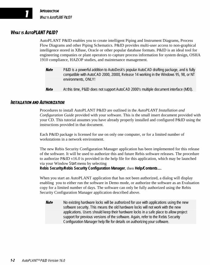
AutoPLANT P&ID enables you to create intelligent Piping and Instrument Diagrams, ProcessFlow Diagrams and other Piping Schematics. P&ID provides multi-user access to non-graphicalintelligence stored in XBase, Oracle or other popular database formats. P&ID is an ideal tool forengineering companies or plant operators to capture process information for system design, OSHA1910 compliance, HAZOP studies, and maintenance management.
>_dU P&ID is a powerful addition to AutoDesk’s popular AutoCAD drafting package, and is fullycompatible with AutoCAD 2000, 2000I, Release 14 working in the Windows 95, 98, or NTenvironments, ONLY!
>_dU At this time, P&ID does not support AutoCAD 2000’s multiple document interface (MDI).
�>CD1<<1D9?> 1>4 �ED8?B9J1D9?>
Procedures to install AutoPLANT P&ID are outlined in the AutoPLANT Installation andConfiguration Guide provided with your software. This is the small insert document provided withyour CD. This tutorial assumes you have already properly installed and configured P&ID using theinstructions provided in that document.
Each P&ID package is licensed for use on only one computer, or for a limited number ofworkstations in a network environment.
The new Rebis Security Configuration Manager application has been implemented for this releaseof the software. It will be used to authorize this and future Rebis software releases. The procedureto authorize P&ID v16.0 is provided in the help file for this application, which may be launchedvia your Window Start menu by selectingRebis Security/Rebis Security Configuration Manager, then Help/Contents….
When you start an AutoPLANT application that has not been authorized, a dialog will displayenabling you to either run the software in Demo mode, or authorize the software as an Evaluationcopy for a limited number of days. The software can only be fully authorized using the RebisSecurity Configuration Manager application described above.
>_dU No existing hardware locks will be authorized for use with applications using the newsoftware security. This means the old hardware locks will not work with the newapplications. Users should keep their hardware locks in a safe place to allow projectsupport for previous versions of the software. Again, refer to the Rebis SecurityConfiguration Manager help file for details on authorizing your software.
9>DB?4E3D9?>
85<@ 1>4 4?3E=5>D1D9?>
Tutorial 1-3
�5<@ 1>4 �?3E=5>D1D9?>
In an effort to provide you with the best application support in the industry, the majority ofAutoPLANT documentation is now provided electronically in the form of HTML help files. Thisimportant decision was made to implement a method for Rebis to quickly update users withinformation on the latest program additions or modifications. Since this information is providedelectronically, users can simply download the latest help files from our web site, without the delayrequired to update and reprint hard copy documentation.
����5<@ 1>4 �����ED?B91< �9<5C
All AutoPLANT help is provided in the latest HTML help format. This tutorial is also providedelectronically in Adobe Acrobat PDF format.
>_dU If you are using a version of Windows prior to Windows 2000, you must have Microsoft’sInternet Explorer v4.0x or later installed and functioning in order to view the help.
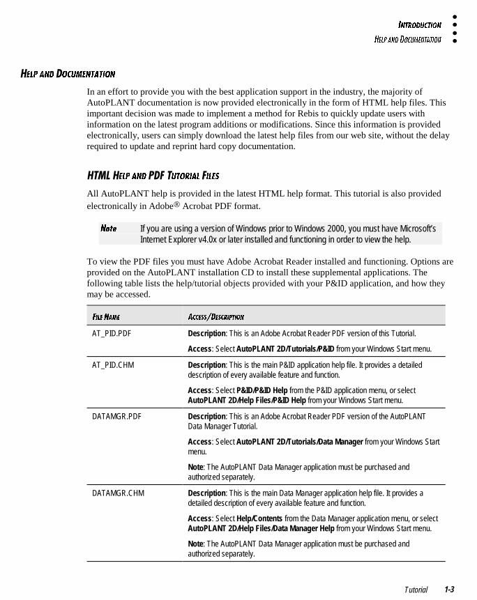
To view the PDF files you must have Adobe Acrobat Reader installed and functioning. Options areprovided on the AutoPLANT installation CD to install these supplemental applications. Thefollowing table lists the help/tutorial objects provided with your P&ID application, and how theymay be accessed.
69<5 >1=5 1335CC�45C3B9@D9?>
AT_PID.PDF Description: This is an Adobe Acrobat Reader PDF version of this Tutorial.
Access: Select AutoPLANT 2D/Tutorials/P&ID from your Windows Start menu.
AT_PID.CHM Description: This is the main P&ID application help file. It provides a detaileddescription of every available feature and function.
Access: Select P&ID/P&ID Help from the P&ID application menu, or selectAutoPLANT 2D/Help Files/P&ID Help from your Windows Start menu.
DATAMGR.PDF Description: This is an Adobe Acrobat Reader PDF version of the AutoPLANTData Manager Tutorial.
Access: Select AutoPLANT 2D/Tutorials/Data Manager from your Windows Startmenu.
Note: The AutoPLANT Data Manager application must be purchased andauthorized separately.
DATAMGR.CHM Description: This is the main Data Manager application help file. It provides adetailed description of every available feature and function.
Access: Select Help/Contents from the Data Manager application menu, or selectAutoPLANT 2D/Help Files/Data Manager Help from your Windows Start menu.
Note: The AutoPLANT Data Manager application must be purchased andauthorized separately.
9>DB?4E3D9?>
85<@ 1>4 4?3E=5>D1D9?>
AutoPLANT® P&ID Version 16.01-4
�
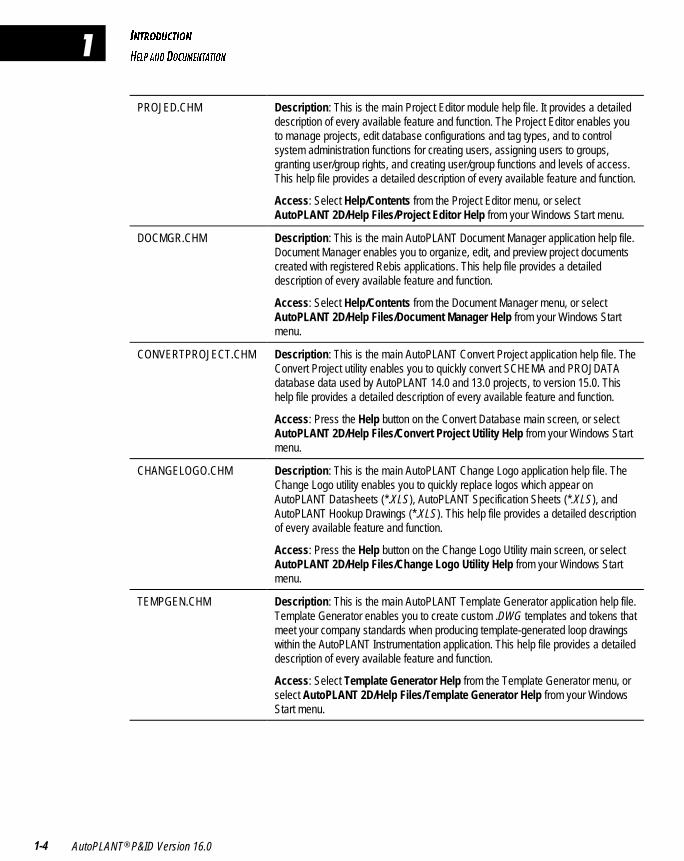
PROJED.CHM Description: This is the main Project Editor module help file. It provides a detaileddescription of every available feature and function. The Project Editor enables youto manage projects, edit database configurations and tag types, and to controlsystem administration functions for creating users, assigning users to groups,granting user/group rights, and creating user/group functions and levels of access.This help file provides a detailed description of every available feature and function.
Access: Select Help/Contents from the Project Editor menu, or selectAutoPLANT 2D/Help Files/Project Editor Help from your Windows Start menu.
DOCMGR.CHM Description: This is the main AutoPLANT Document Manager application help file.Document Manager enables you to organize, edit, and preview project documentscreated with registered Rebis applications. This help file provides a detaileddescription of every available feature and function.
Access: Select Help/Contents from the Document Manager menu, or selectAutoPLANT 2D/Help Files/Document Manager Help from your Windows Startmenu.
CONVERTPROJECT.CHM Description: This is the main AutoPLANT Convert Project application help file. TheConvert Project utility enables you to quickly convert SCHEMA and PROJDATAdatabase data used by AutoPLANT 14.0 and 13.0 projects, to version 15.0. Thishelp file provides a detailed description of every available feature and function.
Access: Press the Help button on the Convert Database main screen, or selectAutoPLANT 2D/Help Files/Convert Project Utility Help from your Windows Startmenu.
CHANGELOGO.CHM Description: This is the main AutoPLANT Change Logo application help file. TheChange Logo utility enables you to quickly replace logos which appear onAutoPLANT Datasheets (*.XLS), AutoPLANT Specification Sheets (*.XLS), andAutoPLANT Hookup Drawings (*.XLS). This help file provides a detailed descriptionof every available feature and function.
Access: Press the Help button on the Change Logo Utility main screen, or selectAutoPLANT 2D/Help Files/Change Logo Utility Help from your Windows Startmenu.
TEMPGEN.CHM Description: This is the main AutoPLANT Template Generator application help file.Template Generator enables you to create custom .DWG templates and tokens thatmeet your company standards when producing template-generated loop drawingswithin the AutoPLANT Instrumentation application. This help file provides a detaileddescription of every available feature and function.
Access: Select Template Generator Help from the Template Generator menu, orselect AutoPLANT 2D/Help Files/Template Generator Help from your WindowsStart menu.
9>DB?4E3D9?>
85<@ 1>4 4?3E=5>D1D9?>
Tutorial 1-5
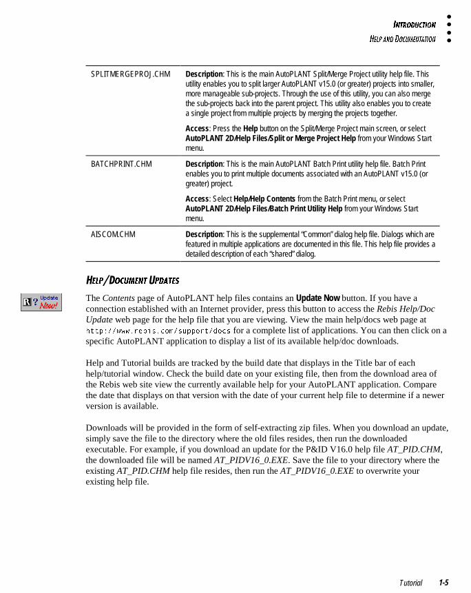
SPLITMERGEPROJ.CHM Description: This is the main AutoPLANT Split/Merge Project utility help file. Thisutility enables you to split larger AutoPLANT v15.0 (or greater) projects into smaller,more manageable sub-projects. Through the use of this utility, you can also mergethe sub-projects back into the parent project. This utility also enables you to createa single project from multiple projects by merging the projects together.
Access: Press the Help button on the Split/Merge Project main screen, or selectAutoPLANT 2D/Help Files/Split or Merge Project Help from your Windows Startmenu.
BATCHPRINT.CHM Description: This is the main AutoPLANT Batch Print utility help file. Batch Printenables you to print multiple documents associated with an AutoPLANT v15.0 (orgreater) project.
Access: Select Help/Help Contents from the Batch Print menu, or selectAutoPLANT 2D/Help Files/Batch Print Utility Help from your Windows Startmenu.
AISCOM.CHM Description: This is the supplemental “Common” dialog help file. Dialogs which arefeatured in multiple applications are documented in this file. This help file provides adetailed description of each “shared” dialog.
�5<@ �?3E=5>D �@41D5C
The Contents page of AutoPLANT help files contains an Update Now button. If you have aconnection established with an Internet provider, press this button to access the Rebis Help/DocUpdate web page for the help file that you are viewing. View the main help/docs web page atKWWS���ZZZ�UHELV�FRP�VXSSRUW�GRFV for a complete list of applications. You can then click on aspecific AutoPLANT application to display a list of its available help/doc downloads.
Help and Tutorial builds are tracked by the build date that displays in the Title bar of eachhelp/tutorial window. Check the build date on your existing file, then from the download area ofthe Rebis web site view the currently available help for your AutoPLANT application. Comparethe date that displays on that version with the date of your current help file to determine if a newerversion is available.
Downloads will be provided in the form of self-extracting zip files. When you download an update,simply save the file to the directory where the old files resides, then run the downloadedexecutable. For example, if you download an update for the P&ID V16.0 help file AT_PID.CHM,the downloaded file will be named AT_PIDV16_0.EXE. Save the file to your directory where theexisting AT_PID.CHM help file resides, then run the AT_PIDV16_0.EXE to overwrite yourexisting help file.
9>DB?4E3D9?>
85<@ 1>4 4?3E=5>D1D9?>
AutoPLANT® P&ID Version 16.01-6
�
������5<@ �B71>9J1D9?>
AutoPLANT P&ID’s on-line Help is the source for answers to any questions you might have aboutprogram features and functionality. All P&ID command dialogs provide a help button to quicklydisplay context-sensitive help on that option. P&ID Help includes the following main topic areas:
� New Features: Provides links to new and modified features by version number.
� Getting Started: Provides an introduction to the interface, and provides a description on how tobest use the help system.
� Menu Command Reference: This folder is organized to closely match the structure of the P&IDand P&ID-Tools menus. This should enable you to quickly locate help on a specific menuoption. In general, the help for each command resides in a separate folder under the menuname folder where it exists in the menu.
� Toolbar Command Reference: This folder provides a reference to the P&ID toolbars and thecommands associated.
� User Procedure How To…: The How To sub folders in this section includes a set of procedure topics that describe how perform tasks in the P&ID application.
� Customization: This section provides an extensive reference to customizing P&ID. TheProgram Customization and Component Customization areas provide an overview of each ofthe main customization categories, with links to specific How To procedures to customizethe respective areas of the application.
� Technical Support: Contains information on how and when to contact our Technical Supportstaff. This section includes telephone and fax numbers, as well as a live web link to the Rebisweb site for the latest support information.
� Adding Your Help: Rebis has developed a simple system to enable Dealers, Contractors, Users,etc. to provide links to their own custom HTML help system within each AutoPLANTapplication's help system. This area of the help explains how to connect your own HTML helpto each AutoPLANT application’s help system.
9>DB?4E3D9?>
651DEB5C
Tutorial 1-7
�B9>D9>7 �5<@ �ED?B91< �9<5C
The HTML format of Rebis help systems makes printing easier than ever. To print a topic, simplyselect it from the Table of Contents, then press the Print button. Enable the Print the selected topicradio button in the dialog displayed, then press OK. If you want to print all of the topics that residein a particular folder and all of its sub-folders, simply select the folder and press Print, then enablethe Print the selected heading and all subtopics radio button, then press OK. All topics in and belowthe selected folder will be printed in the order that they are defined in the folder.
PDF files may be printed by selecting File/Print, then selecting the range of pages to print.
�51DEB5C
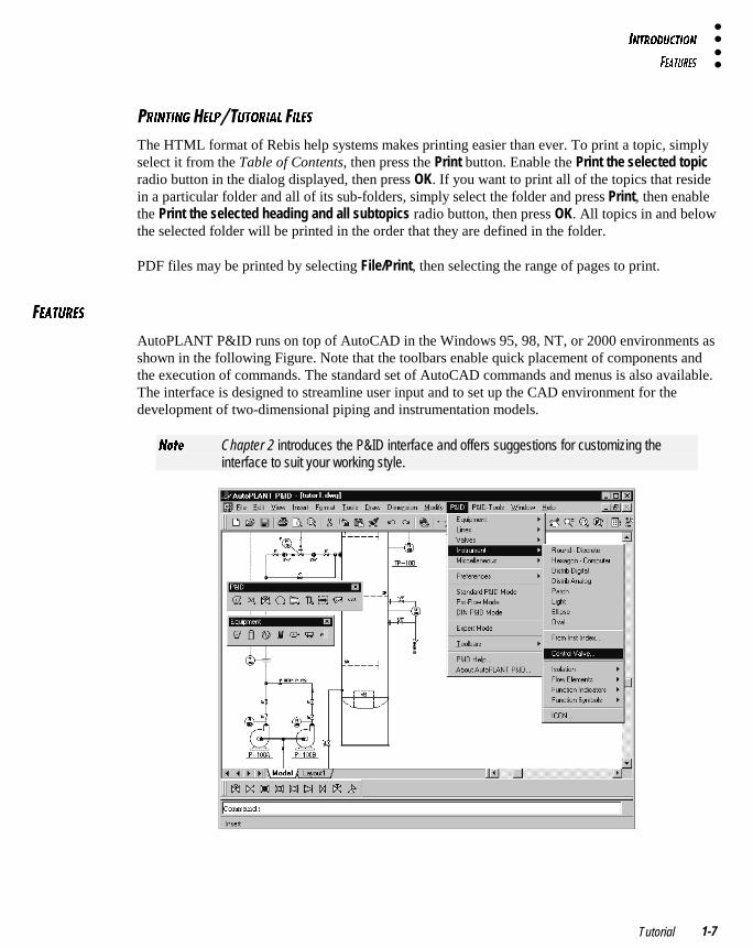
AutoPLANT P&ID runs on top of AutoCAD in the Windows 95, 98, NT, or 2000 environments asshown in the following Figure. Note that the toolbars enable quick placement of components andthe execution of commands. The standard set of AutoCAD commands and menus is also available.The interface is designed to streamline user input and to set up the CAD environment for thedevelopment of two-dimensional piping and instrumentation models.
>_dU Chapter 2 introduces the P&ID interface and offers suggestions for customizing theinterface to suit your working style.
9>DB?4E3D9?>
651DEB5C
AutoPLANT® P&ID Version 16.01-8
�
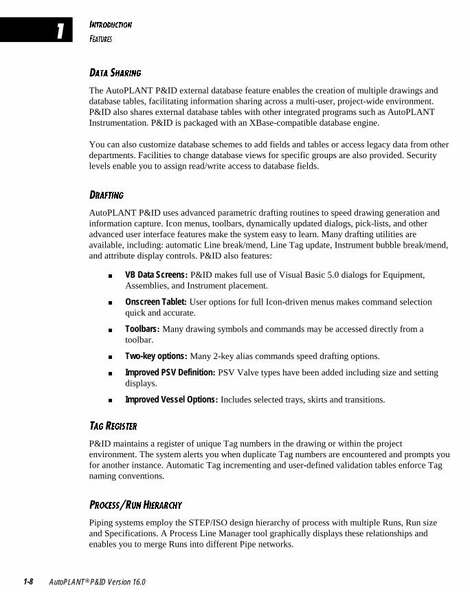
�1D1 �81B9>7
The AutoPLANT P&ID external database feature enables the creation of multiple drawings anddatabase tables, facilitating information sharing across a multi-user, project-wide environment.P&ID also shares external database tables with other integrated programs such as AutoPLANTInstrumentation. P&ID is packaged with an XBase-compatible database engine.
You can also customize database schemes to add fields and tables or access legacy data from otherdepartments. Facilities to change database views for specific groups are also provided. Securitylevels enable you to assign read/write access to database fields.
�B16D9>7
AutoPLANT P&ID uses advanced parametric drafting routines to speed drawing generation andinformation capture. Icon menus, toolbars, dynamically updated dialogs, pick-lists, and otheradvanced user interface features make the system easy to learn. Many drafting utilities areavailable, including: automatic Line break/mend, Line Tag update, Instrument bubble break/mend,and attribute display controls. P&ID also features:
� VB Data Screens: P&ID makes full use of Visual Basic 5.0 dialogs for Equipment,Assemblies, and Instrument placement.
� Onscreen Tablet: User options for full Icon-driven menus makes command selectionquick and accurate.
� Toolbars: Many drawing symbols and commands may be accessed directly from atoolbar.
� Two-key options: Many 2-key alias commands speed drafting options.
� Improved PSV Definition: PSV Valve types have been added including size and settingdisplays.
� Improved Vessel Options: Includes selected trays, skirts and transitions.
�17 �579CD5B
P&ID maintains a register of unique Tag numbers in the drawing or within the projectenvironment. The system alerts you when duplicate Tag numbers are encountered and prompts youfor another instance. Automatic Tag incrementing and user-defined validation tables enforce Tagnaming conventions.
�B?35CC �E> �95B1B38I
Piping systems employ the STEP/ISO design hierarchy of process with multiple Runs, Run sizeand Specifications. A Process Line Manager tool graphically displays these relationships andenables you to merge Runs into different Pipe networks.
9>DB?4E3D9?>
651DEB5C
Tutorial 1-9
�?>C9CD5>3I �853;5B
The Consistency Checker provides interactive checking of connectivity and consistency such asbranch Lines that exceed the size of a header, or Valve sizes matching associated Pipe. Interactiveviewing and printed reports are also available.
�I=2?<C ���CC5=2<95C
P&ID includes over 400 symbols that conform to ISA standards. P&ID contains a complete set ofpiping and Instrument Line fonts, such as Major, Minor, Pneumatic, and Electric. DIN line stylesare also supported. A library tool supports symbol customization and management. New symbolscan be created and intelligently linked to the database.
�B71>9J54���?>C9CD5>D<I �33EB1D5 �B1G9>7 �9<5C
� Data Storage Options: Two data storage options are available:
� Store all data in the drawing. Only a single document needs to be saved.
� Store non-graphical data in a single external database file, providing externalaccess to the data without having to perform import/export functions.
� Automatic Updates: Drawing intelligence and annotation are updated when edits havebeen made to the external database.
� Intelligent Line Annotation: When Line attributes are updated, Line annotations at alloccurrences on the drawing are updated.
� To/From Control: Provides automatic lookup and reuse of To/From data across multipledrawings. An active list of open To/From arrows can be used to initiate Line routing.
� Tag Numbers: Ability to ensure unique Tag numbers across multiple drawings.
� Assemblies Across Multiple Drawings: Make, insert, and delete Assemblies in differentdrawings. Assemblies may be previewed prior to insertion and can be instructed to breaka Process Line where they are inserted.
� Mass Balance Import Tables: Import a Mass Balance Table from HYSIM.
E<D9@<5 �95GC 6?B �?>�7B1@8931< �1D1
Data from P&ID can be displayed in multiple views, including the Design View, which presentsdata associated with the item during the design phase. The Maintenance View displays dataassociated with the item after installation. All views are fully customizable including read/writeprivileges.
9>DB?4E3D9?>
12?ED D89C DED?B91<
AutoPLANT® P&ID Version 16.01-10
�
�=@?BD �H@?BD �1@129<9D95C
P&ID drawings can be imported into a project environment with full consistency checking. Inaddition, P&IDs created in a project-wide environment can be exported as a stand-alone drawingincluding all related data files.
�5@?BDC
One-step menu commands enable you to quickly create Line Lists, Valve Lists, Equipment Lists,and Instrument Indexes.
�2?ED D89C ED?B91<
This Tutorial is designed to teach you the features of the AutoPLANT P&ID and AutoPLANTDocument Manager applications. The Tutorial is divided into three sections — Basic, Advanced,and Supplemental Applications.
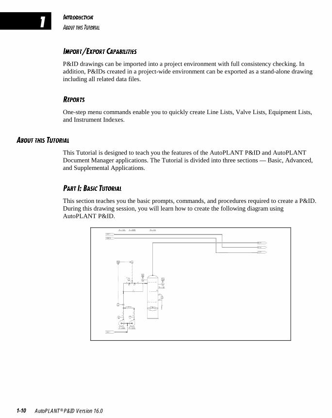
�1BD ����1C93 �ED?B91<
This section teaches you the basic prompts, commands, and procedures required to create a P&ID.During this drawing session, you will learn how to create the following diagram usingAutoPLANT P&ID.

9>DB?4E3D9?>
12?ED D89C DED?B91<
Tutorial 1-11
�1BD �����4F1>354 �ED?B91<
These chapters familiarize you with the features of the AutoPLANT P&ID program related toproject environments including:
� How to convert a stand-alone drawing into an on-line project environment drawing.
� How to perform consistency checks.
� How to create complicated assemblies for insertion into project drawings.
� How to link documents created with external programs.
�1BD ������E@@<5=5>D1< �@@<931D9?>C
This chapter introduces you to the AutoPLANT Document Manager application which enables youto organize, revise, and preview project documents.
9>DB?4E3D9?>
4?3E=5>D1D9?> 3?>F5>D9?>C
AutoPLANT® P&ID Version 16.01-12
�
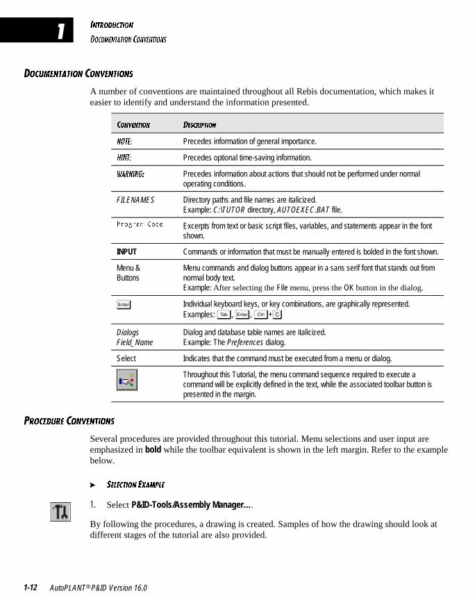
�?3E=5>D1D9?> �?>F5>D9?>C
A number of conventions are maintained throughout all Rebis documentation, which makes iteasier to identify and understand the information presented.
3?>F5>D9?> 45C3B9@D9?>
>?D5* Precedes information of general importance.
89>D* Precedes optional time-saving information.
G1B>9>7* Precedes information about actions that should not be performed under normaloperating conditions.
FILENAMES Directory paths and file names are italicized.Example: C:\TUTOR directory, AUTOEXEC.BAT file.
3URJUDP &RGH Excerpts from text or basic script files, variables, and statements appear in the fontshown.
INPUT Commands or information that must be manually entered is bolded in the font shown.
Menu &Buttons
Menu commands and dialog buttons appear in a sans serif font that stands out fromnormal body text.Example: After selecting the File menu, press the OK button in the dialog.
� Individual keyboard keys, or key combinations, are graphically represented.Examples: �, �, �+�
DialogsField_Name
Dialog and database table names are italicized.Example: The Preferences dialog.
Select Indicates that the command must be executed from a menu or dialog.
Throughout this Tutorial, the menu command sequence required to execute acommand will be explicitly defined in the text, while the associated toolbar button ispresented in the margin.
�B?354EB5 �?>F5>D9?>C
Several procedures are provided throughout this tutorial. Menu selections and user input areemphasized in bold while the toolbar equivalent is shown in the left margin. Refer to the examplebelow.
� C5<53D9?> 5H1=@<5
!� Select P&ID-Tools/Assembly Manager….
By following the procedures, a drawing is created. Samples of how the drawing should look atdifferent stages of the tutorial are also provided.
9>DB?4E3D9?>
D538>931< CE@@?BD 1>4 DB19>9>7
Tutorial 1-13
538>931< E@@?BD 1>4 B19>9>7
Rebis' trained personnel are available to provide quality support to customers on all currentproduct lines. To inquire about technical support options, contact Rebis’ corporate headquarters at(925) 933-2525.
� Explore On-line Help for an answer to your question.
�I@5C ?6 �538>931< �E@@?BD
• Maintenance, Enhancement and Support (MES): Users who have purchased an MES contractreceive priority Technical Support on a toll-free 800 support line. In addition, on-line supportis provided via the internet. As an MES customer, Rebis will do its best to resolve yourproblem immediately.
>_dU Please contact your Rebis Inside Sales Representative for more information on MES.
� Internet Support: Online Support is a reserved area for active MES subscribers. A few benefitsare described below:
• Input and track support incidents related to your organization. You will be automaticallynotified via email when the status of your support incident has changed. New incidents godirectly into our Technical Support database, and you can track the incidents remotelyover the web. You can even change the status of your incident live!
• View our Solutions Database. Much more than a set of FAQs, this is a comprehensivedatabase of solutions compiled and maintained by our Tech Support staff.
• View Software Bugs. Rebis is confident about our products, and we want to help youresolve any problems you may be experiencing. Because of this, we expose our Trackerdatabase to our customers.
You can see the advantages of obtaining an MES contract: Search the knowledge browser fora list of solutions, see if your problem has been reported already as a bug, add a new incidentand track it... all from the web and without requiring a phone call!
The Rebis Support URL is www.rebis.com/support.
� Fax Support: Fax traditional inquiries to (985) 893-5293; 24hrs, 7days/week.

9>DB?4E3D9?>
@B5�CD1BD 3853;<9CD
AutoPLANT® P&ID Version 16.01-14
�
�B5�D1BD �853;<9CD
�>CD1<< �ED?�����������B?7B1= �9<5C
Before you can begin this Tutorial you must install the AutoPLANT P&ID Version 16.0 programfiles on to your hard disk and configure your computer system to run the software. Theseprocedures are explained in the Installation and Configuration Guide provided with your CD.
�B51D5 ���?B;9>7 �ED?B91< �9B53D?BI
As part of this tutorial, you will create drawings and diagrams. As this is generated, a database iscreated “on the fly” which contains information about the objects. In an effort to consolidate thisinformation, create a project directory called TUTOR and periodically save the drawing in thislocation. After the tutorial is finished, you can delete the directory and its files.
��������������� ���������
This tutorial introduces you to some of the basic features and functions of theAutoPLANT P&ID application. This section also provides detailed explanations ofmany P&ID prompts.
CHAPTER 2: GETTING STARTED
CHAPTER 3: EQUIPMENT, PROCESS LINES, AND CONTROL STATIONS
CHAPTER 4: FLOW LOOPS, VALVES, AND INSTRUMENTS
CHAPTER 5: ASSEMBLIES, EQUIPMENT TRIM, FLANGES, & ARROWS
CHAPTER 6: PROCESS MANAGER AND EDITING FEATURES
� � � � � �
�

������� ������
In this chapter, you will learn some of the basic features of the AutoPLANT P&IDapplication. You will also learn how to launch AutoPLANT P&ID, select a project, andstart a new drawing.
STARTING P&ID 2-2
STARTING A NEW DRAWING AND SELECTING A PROJECT 2-2
A TOUR OF THE INTERFACE 2-5
� � � � � � � � �
�
75DD9>7 CD1BD54
CD1BD9>7 @�94
AutoPLANT® P&ID Version 16.02-2
�
D1BD9>7 � ��
� D? CD1BD @�94
!� Install and configure the software as instructed in the Installation and Configuration insertprovided with your CD.
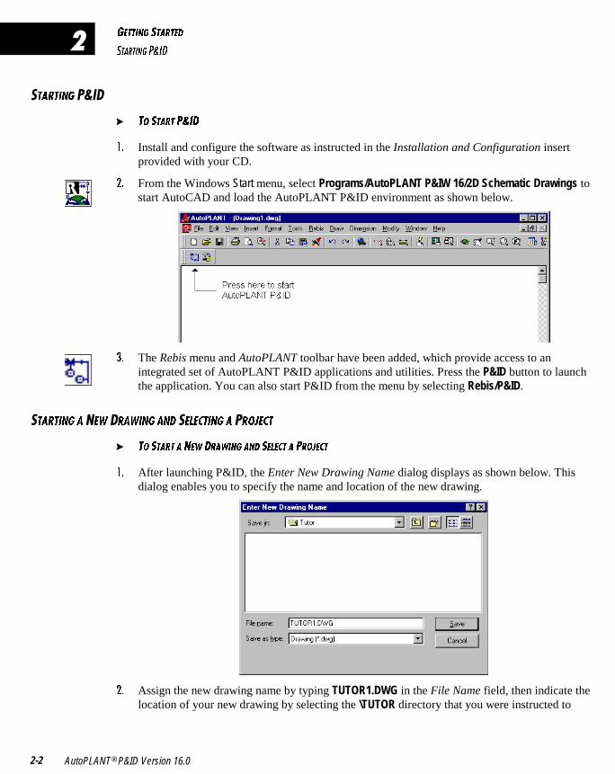
"� From the Windows Start menu, select Programs/AutoPLANT P&IW 16/2D Schematic Drawings tostart AutoCAD and load the AutoPLANT P&ID environment as shown below.
#� The Rebis menu and AutoPLANT toolbar have been added, which provide access to anintegrated set of AutoPLANT P&ID applications and utilities. Press the P&ID button to launchthe application. You can also start P&ID from the menu by selecting Rebis/P&ID.
D1BD9>7 1 �5G �B1G9>7 1>4 5<53D9>7 1 �B?:53D
� D? CD1BD 1 >5G 4B1G9>7 1>4 C5<53D 1 @B?:53D
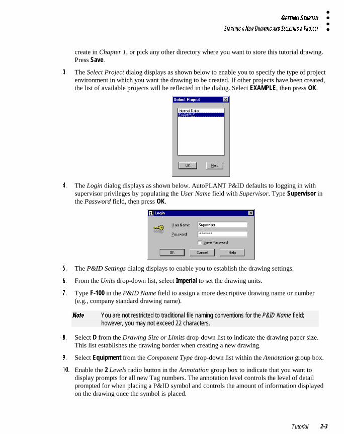
!� After launching P&ID, the Enter New Drawing Name dialog displays as shown below. Thisdialog enables you to specify the name and location of the new drawing.
"� Assign the new drawing name by typing TUTOR1.DWG in the File Name field, then indicate thelocation of your new drawing by selecting the \TUTOR directory that you were instructed to
75DD9>7 CD1BD54
CD1BD9>7 1 >5G 4B1G9>7 1>4 C5<53D9>7 1 @B?:53D
Tutorial 2-3
create in Chapter 1, or pick any other directory where you want to store this tutorial drawing.Press Save.
#� The Select Project dialog displays as shown below to enable you to specify the type of projectenvironment in which you want the drawing to be created. If other projects have been created,the list of available projects will be reflected in the dialog. Select EXAMPLE, then press OK.
$� The Login dialog displays as shown below. AutoPLANT P&ID defaults to logging in withsupervisor privileges by populating the User Name field with Supervisor. Type Supervisor inthe Password field, then press OK.
%� The P&ID Settings dialog displays to enable you to establish the drawing settings.
&� From the Units drop-down list, select Imperial to set the drawing units.
'� Type F-100 in the P&ID Name field to assign a more descriptive drawing name or number(e.g., company standard drawing name).
>_dU You are not restricted to traditional file naming conventions for the P&ID Name field;however, you may not exceed 22 characters.
(� Select D from the Drawing Size or Limits drop-down list to indicate the drawing paper size.This list establishes the drawing border when creating a new drawing.
)� Select Equipment from the Component Type drop-down list within the Annotation group box.
! � Enable the 2 Levels radio button in the Annotation group box to indicate that you want todisplay prompts for all new Tag numbers. The annotation level controls the level of detailprompted for when placing a P&ID symbol and controls the amount of information displayedon the drawing once the symbol is placed.
75DD9>7 CD1BD54
CD1BD9>7 1 >5G 4B1G9>7 1>4 C5<53D9>7 1 @B?:53D
AutoPLANT® P&ID Version 16.02-4
�
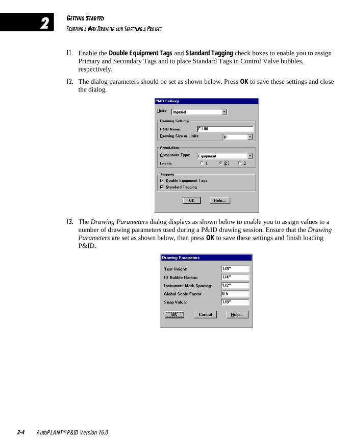
!!� Enable the Double Equipment Tags and Standard Tagging check boxes to enable you to assignPrimary and Secondary Tags and to place Standard Tags in Control Valve bubbles,respectively.
!"� The dialog parameters should be set as shown below. Press OK to save these settings and closethe dialog.
!#� The Drawing Parameters dialog displays as shown below to enable you to assign values to anumber of drawing parameters used during a P&ID drawing session. Ensure that the DrawingParameters are set as shown below, then press OK to save these settings and finish loadingP&ID.
75DD9>7 CD1BD54
1 D?EB ?6 D85 9>D5B6135
Tutorial 2-5
��?EB ?6 D85 �>D5B6135
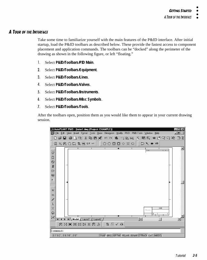
Take some time to familiarize yourself with the main features of the P&ID interface. After initialstartup, load the P&ID toolbars as described below. These provide the fastest access to componentplacement and application commands. The toolbars can be “docked” along the perimeter of thedrawing as shown in the following figure, or left “floating.”
!� Select P&ID/Toolbars/PID Main.
"� Select P&ID/Toolbars/Equipment.
#� Select P&ID/Toolbars/Lines.
$� Select P&ID/Toolbars/Valves.
%� Select P&ID/Toolbars/Instruments.
&� Select P&ID/Toolbars/Misc Symbols.
'� Select P&ID/Toolbars/Tools.
After the toolbars open, position them as you would like them to appear in your current drawingsession.
75DD9>7 CD1BD54
1 D?EB ?6 D85 9>D5B6135
AutoPLANT® P&ID Version 16.02-6
�
Experiment with the placement of these toolbars as you will be accessing them frequently duringthe tutorial drawing sessions. In the example above, the Equipment and Lines toolbars were movedto the left of the drawing area, the Valves and Tools toolbars were moved to the bottom of thedrawing area, and the P&ID, Instruments, and Misc Symbols toolbars were docked along the top ofthe drawing area.
The size of the toolbar icons can also be customized. Toggle the display of large or small buttonsaccording to your preference and monitor size by right-clicking on any button in a toolbar, thenselecting Customize…. When AutoCAD’s Toolbars dialog appears, enable/disable the LargeButtons option as desired, then press Close.
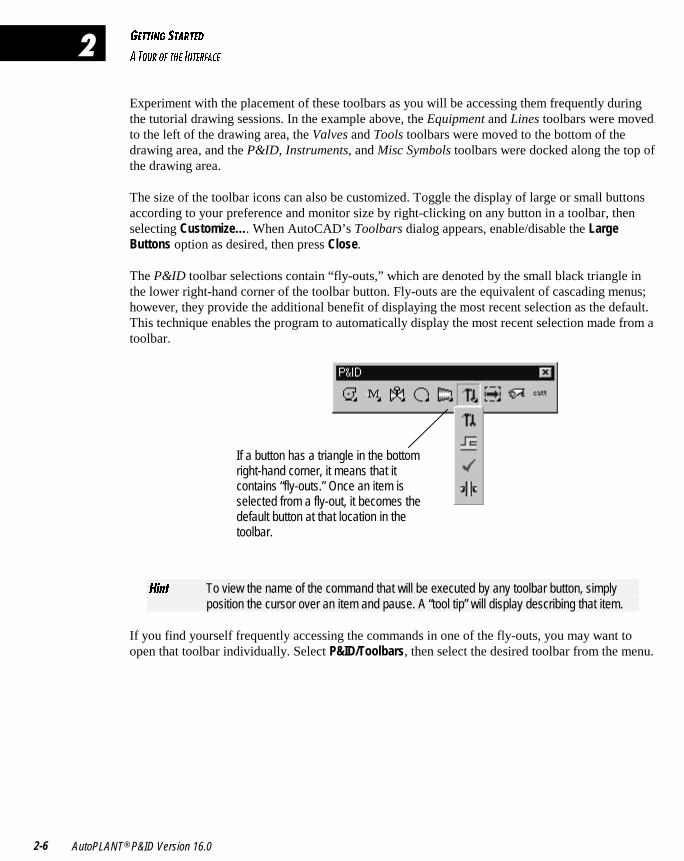
The P&ID toolbar selections contain “fly-outs,” which are denoted by the small black triangle inthe lower right-hand corner of the toolbar button. Fly-outs are the equivalent of cascading menus;however, they provide the additional benefit of displaying the most recent selection as the default.This technique enables the program to automatically display the most recent selection made from atoolbar.
If a button has a triangle in the bottomright-hand corner, it means that itcontains “fly-outs.” Once an item isselected from a fly-out, it becomes thedefault button at that location in thetoolbar.
8Y^d To view the name of the command that will be executed by any toolbar button, simplyposition the cursor over an item and pause. A “tool tip” will display describing that item.
If you find yourself frequently accessing the commands in one of the fly-outs, you may want toopen that toolbar individually. Select P&ID/Toolbars, then select the desired toolbar from the menu.
������������ ����������� ��������������
In this chapter, you will learn how to place a Pump and Tower in your drawing,connect the Equipment using a 6” Major Process Line, and build a Control Stationusing Gate Valves, Control Valves, and Reducers.
PLACING EQUIPMENT 3-2
DRAWING PROCESS LINES 3-7
BUILDING A CONTROL STATION 3-9
� � � � � � � � �
�
5AE9@=5>D� @B?35CC <9>5C� 1>4 3?>DB?< CD1D9?>C
@<139>7 5AE9@=5>D
AutoPLANT® P&ID Version 16.03-2
�
�<139>7 �AE9@=5>D
In this section, you will learn how to place Equipment in your new drawing. You will begin by firstplacing Equipment so that when you start drawing Pipe, To/From information is automaticallyrecorded.
� D? @<135 1 @E=@ 9> 1 4B1G9>7
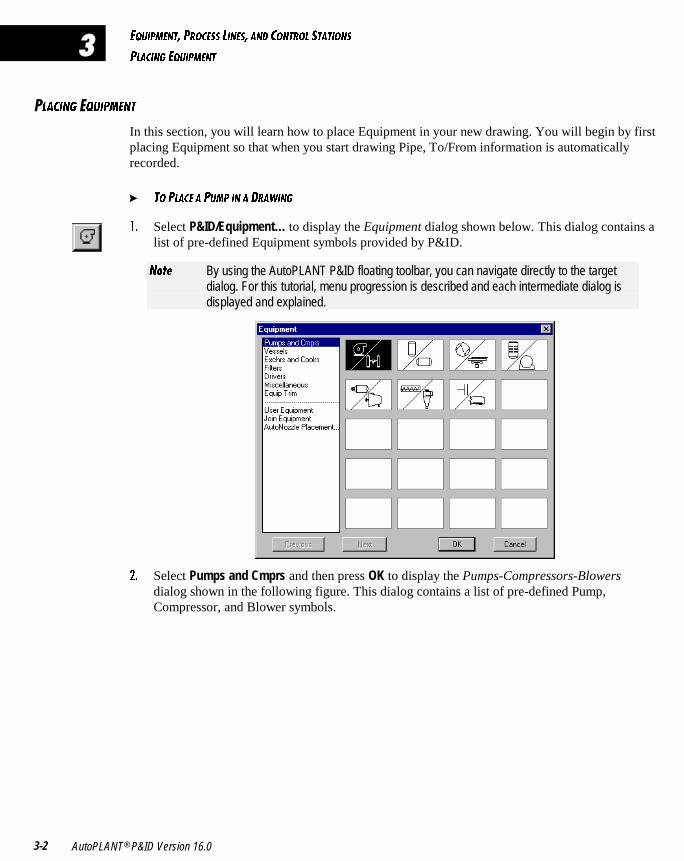
!� Select P&ID/Equipment… to display the Equipment dialog shown below. This dialog contains alist of pre-defined Equipment symbols provided by P&ID.
>_dU By using the AutoPLANT P&ID floating toolbar, you can navigate directly to the targetdialog. For this tutorial, menu progression is described and each intermediate dialog isdisplayed and explained.
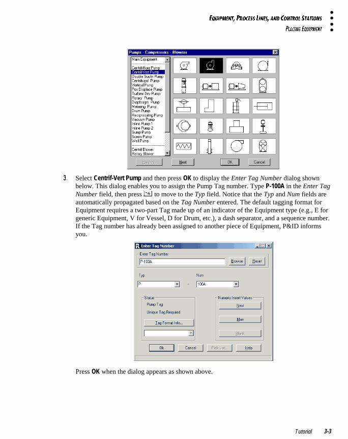
"� Select Pumps and Cmprs and then press OK to display the Pumps-Compressors-Blowersdialog shown in the following figure. This dialog contains a list of pre-defined Pump,Compressor, and Blower symbols.
5AE9@=5>D� @B?35CC <9>5C� 1>4 3?>DB?< CD1D9?>C
@<139>7 5AE9@=5>D
Tutorial 3-3
#� Select Centrif-Vert Pump and then press OK to display the Enter Tag Number dialog shownbelow. This dialog enables you to assign the Pump Tag number. Type P-100A in the Enter TagNumber field, then press v to move to the Typ field. Notice that the Typ and Num fields areautomatically propagated based on the Tag Number entered. The default tagging format forEquipment requires a two-part Tag made up of an indicator of the Equipment type (e.g., E forgeneric Equipment, V for Vessel, D for Drum, etc.), a dash separator, and a sequence number.If the Tag number has already been assigned to another piece of Equipment, P&ID informsyou.
Press OK when the dialog appears as shown above.
5AE9@=5>D� @B?35CC <9>5C� 1>4 3?>DB?< CD1D9?>C
@<139>7 5AE9@=5>D
AutoPLANT® P&ID Version 16.03-4
�
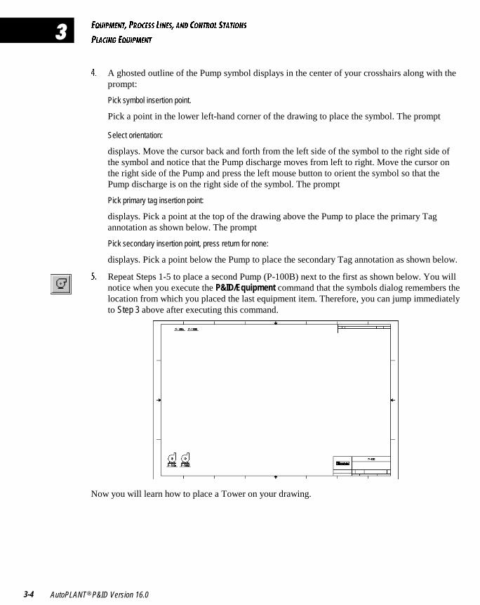
$� A ghosted outline of the Pump symbol displays in the center of your crosshairs along with theprompt:
Pick symbol insertion point.
Pick a point in the lower left-hand corner of the drawing to place the symbol. The prompt
Select orientation:
displays. Move the cursor back and forth from the left side of the symbol to the right side ofthe symbol and notice that the Pump discharge moves from left to right. Move the cursor onthe right side of the Pump and press the left mouse button to orient the symbol so that thePump discharge is on the right side of the symbol. The prompt
Pick primary tag insertion point:
displays. Pick a point at the top of the drawing above the Pump to place the primary Tagannotation as shown below. The prompt
Pick secondary insertion point, press return for none:
displays. Pick a point below the Pump to place the secondary Tag annotation as shown below.
%� Repeat Steps 1-5 to place a second Pump (P-100B) next to the first as shown below. You willnotice when you execute the P&ID/Equipment command that the symbols dialog remembers thelocation from which you placed the last equipment item. Therefore, you can jump immediatelyto Step 3 above after executing this command.
Now you will learn how to place a Tower on your drawing.
5AE9@=5>D� @B?35CC <9>5C� 1>4 3?>DB?< CD1D9?>C
@<139>7 5AE9@=5>D
Tutorial 3-5
� D? @<135 1 D?G5B 9> 1 4B1G9>7
!� Select P&ID/Equipment… to display the Pumps-Compressors-Blowers dialog.
"� Select Main Equipment, then press OK to display the Equipment dialog.
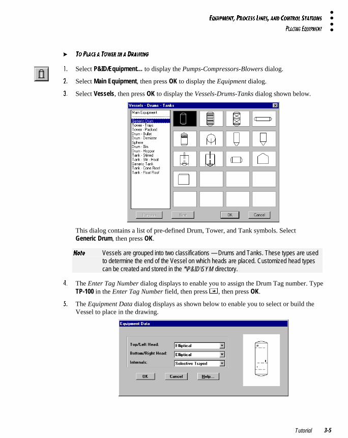
#� Select Vessels, then press OK to display the Vessels-Drums-Tanks dialog shown below.
This dialog contains a list of pre-defined Drum, Tower, and Tank symbols. SelectGeneric Drum, then press OK.
>_dU Vessels are grouped into two classifications — Drums and Tanks. These types are usedto determine the end of the Vessel on which heads are placed. Customized head typescan be created and stored in the *\P&ID\SYM directory.
$� The Enter Tag Number dialog displays to enable you to assign the Drum Tag number. TypeTP-100 in the Enter Tag Number field, then press v, then press OK.
%� The Equipment Data dialog displays as shown below to enable you to select or build theVessel to place in the drawing.
5AE9@=5>D� @B?35CC <9>5C� 1>4 3?>DB?< CD1D9?>C
@<139>7 5AE9@=5>D
AutoPLANT® P&ID Version 16.03-6
�
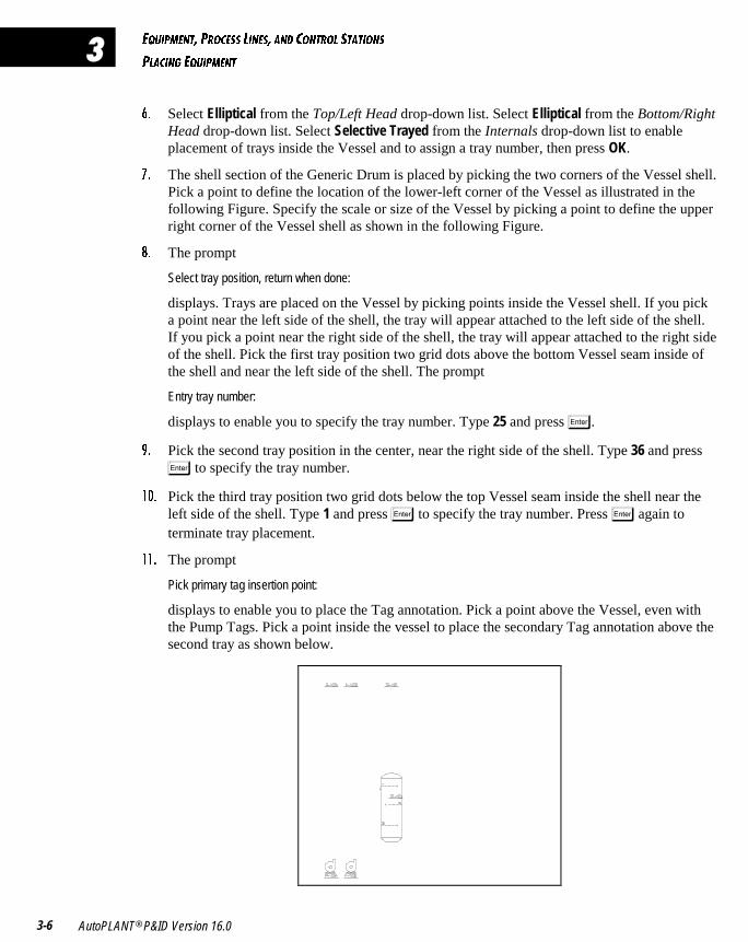
&� Select Elliptical from the Top/Left Head drop-down list. Select Elliptical from the Bottom/RightHead drop-down list. Select Selective Trayed from the Internals drop-down list to enableplacement of trays inside the Vessel and to assign a tray number, then press OK.
'� The shell section of the Generic Drum is placed by picking the two corners of the Vessel shell.Pick a point to define the location of the lower-left corner of the Vessel as illustrated in thefollowing Figure. Specify the scale or size of the Vessel by picking a point to define the upperright corner of the Vessel shell as shown in the following Figure.
(� The prompt
Select tray position, return when done:
displays. Trays are placed on the Vessel by picking points inside the Vessel shell. If you picka point near the left side of the shell, the tray will appear attached to the left side of the shell.If you pick a point near the right side of the shell, the tray will appear attached to the right sideof the shell. Pick the first tray position two grid dots above the bottom Vessel seam inside ofthe shell and near the left side of the shell. The prompt
Entry tray number:
displays to enable you to specify the tray number. Type 25 and press �.
)� Pick the second tray position in the center, near the right side of the shell. Type 36 and press
� to specify the tray number.
! � Pick the third tray position two grid dots below the top Vessel seam inside the shell near theleft side of the shell. Type 1 and press � to specify the tray number. Press � again toterminate tray placement.
!!� The prompt
Pick primary tag insertion point:
displays to enable you to place the Tag annotation. Pick a point above the Vessel, even withthe Pump Tags. Pick a point inside the vessel to place the secondary Tag annotation above thesecond tray as shown below.
5AE9@=5>D� @B?35CC <9>5C� 1>4 3?>DB?< CD1D9?>C
4B1G9>7 @B?35CC <9>5C
Tutorial 3-7
�B1G9>7 �B?35CC �9>5C
� D? 4B1G @B?35CC <9>5C
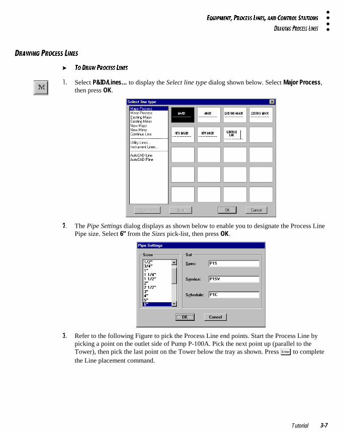
!� Select P&ID/Lines… to display the Select line type dialog shown below. Select Major Process,then press OK.
"� The Pipe Settings dialog displays as shown below to enable you to designate the Process LinePipe size. Select 6” from the Sizes pick-list, then press OK.
#� Refer to the following Figure to pick the Process Line end points. Start the Process Line bypicking a point on the outlet side of Pump P-100A. Pick the next point up (parallel to theTower), then pick the last point on the Tower below the tray as shown. Press � to completethe Line placement command.
5AE9@=5>D� @B?35CC <9>5C� 1>4 3?>DB?< CD1D9?>C
4B1G9>7 @B?35CC <9>5C
AutoPLANT® P&ID Version 16.03-8
�
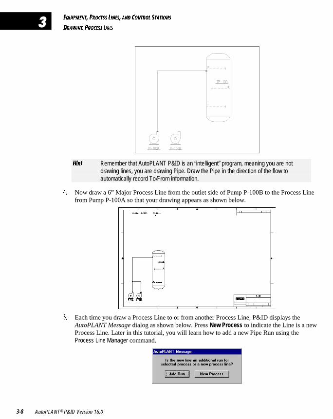
8Y^d Remember that AutoPLANT P&ID is an “intelligent” program, meaning you are notdrawing lines, you are drawing Pipe. Draw the Pipe in the direction of the flow toautomatically record To/From information.
$� Now draw a 6” Major Process Line from the outlet side of Pump P-100B to the Process Linefrom Pump P-100A so that your drawing appears as shown below.
%� Each time you draw a Process Line to or from another Process Line, P&ID displays theAutoPLANT Message dialog as shown below. Press New Process to indicate the Line is a newProcess Line. Later in this tutorial, you will learn how to add a new Pipe Run using theProcess Line Manager command.
5AE9@=5>D� @B?35CC <9>5C� 1>4 3?>DB?< CD1D9?>C
2E9<49>7 1 3?>DB?< CD1D9?>
Tutorial 3-9
�E9<49>7 1 �?>DB?< D1D9?>
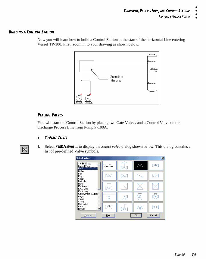
Now you will learn how to build a Control Station at the start of the horizontal Line enteringVessel TP-100. First, zoom in to your drawing as shown below.
Zoom in tothis area.
�<139>7 1<F5C
You will start the Control Station by placing two Gate Valves and a Control Valve on thedischarge Process Line from Pump P-100A.
� D? @<135 F1<F5C
!� Select P&ID/Valves… to display the Select valve dialog shown below. This dialog contains alist of pre-defined Valve symbols.
5AE9@=5>D� @B?35CC <9>5C� 1>4 3?>DB?< CD1D9?>C
2E9<49>7 1 3?>DB?< CD1D9?>
AutoPLANT® P&ID Version 16.03-10
�
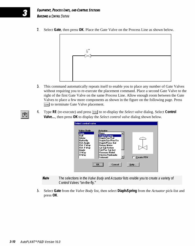
"� Select Gate, then press OK. Place the Gate Valve on the Process Line as shown below.
#� This command automatically repeats itself to enable you to place any number of Gate Valveswithout requiring you to re-execute the placement command. Place a second Gate Valve to theright of the first Gate Valve on the same Process Line. Allow enough room between the GateValves to place a few more components as shown in the figure on the following page. Press
� to terminate Gate Valve placement.
$� Type RE (re-execute) and press � to re-display the Select valve dialog. Select ControlValve…, then press OK to display the Select control valve dialog shown below.
>_dU The selections in the Valve Body and Actuator lists enable you to create a variety ofControl Valves “on-the-fly.”
%� Select Gate from the Valve Body list, then select Diaph/Spring from the Actuator pick-list andpress OK.
5AE9@=5>D� @B?35CC <9>5C� 1>4 3?>DB?< CD1D9?>C
2E9<49>7 1 3?>DB?< CD1D9?>
Tutorial 3-11
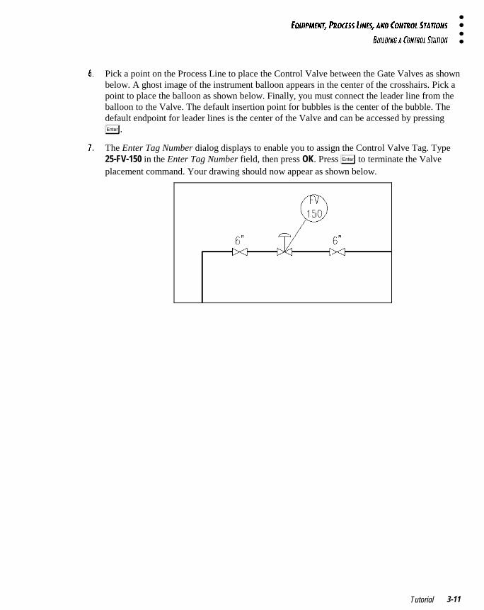
&� Pick a point on the Process Line to place the Control Valve between the Gate Valves as shownbelow. A ghost image of the instrument balloon appears in the center of the crosshairs. Pick apoint to place the balloon as shown below. Finally, you must connect the leader line from theballoon to the Valve. The default insertion point for bubbles is the center of the bubble. Thedefault endpoint for leader lines is the center of the Valve and can be accessed by pressing
�.
'� The Enter Tag Number dialog displays to enable you to assign the Control Valve Tag. Type25-FV-150 in the Enter Tag Number field, then press OK. Press � to terminate the Valveplacement command. Your drawing should now appear as shown below.
5AE9@=5>D� @B?35CC <9>5C� 1>4 3?>DB?< CD1D9?>C
2E9<49>7 1 3?>DB?< CD1D9?>
AutoPLANT® P&ID Version 16.03-12
�
B1G9>7 1 �I@1CC �9>5
In this section, you will draw a Bypass Line, then place a Globe Valve on the Line.
� D? 4B1G 1 2I@1CC <9>5
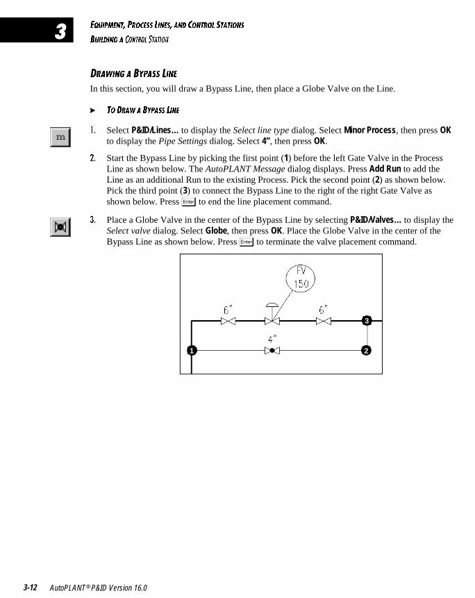
!� Select P&ID/Lines… to display the Select line type dialog. Select Minor Process, then press OKto display the Pipe Settings dialog. Select 4”, then press OK.
"� Start the Bypass Line by picking the first point (1) before the left Gate Valve in the ProcessLine as shown below. The AutoPLANT Message dialog displays. Press Add Run to add theLine as an additional Run to the existing Process. Pick the second point (2) as shown below.Pick the third point (3) to connect the Bypass Line to the right of the right Gate Valve asshown below. Press � to end the line placement command.
#� Place a Globe Valve in the center of the Bypass Line by selecting P&ID/Valves… to display theSelect valve dialog. Select Globe, then press OK. Place the Globe Valve in the center of theBypass Line as shown below. Press � to terminate the valve placement command.
1 2
3
5AE9@=5>D� @B?35CC <9>5C� 1>4 3?>DB?< CD1D9?>C
2E9<49>7 1 3?>DB?< CD1D9?>
Tutorial 3-13
�<139>7 �54E35BC
In this section, you will place Reducers on both sides of the Control Valve.
� D? @<135 B54E35BC
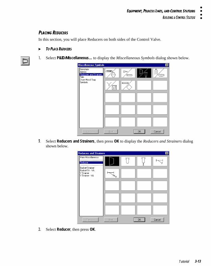
!� Select P&ID/Miscellaneous… to display the Miscellaneous Symbols dialog shown below.
"� Select Reducers and Strainers, then press OK to display the Reducers and Strainers dialogshown below.
#� Select Reducer, then press OK.
5AE9@=5>D� @B?35CC <9>5C� 1>4 3?>DB?< CD1D9?>C
2E9<49>7 1 3?>DB?< CD1D9?>
AutoPLANT® P&ID Version 16.03-14
�
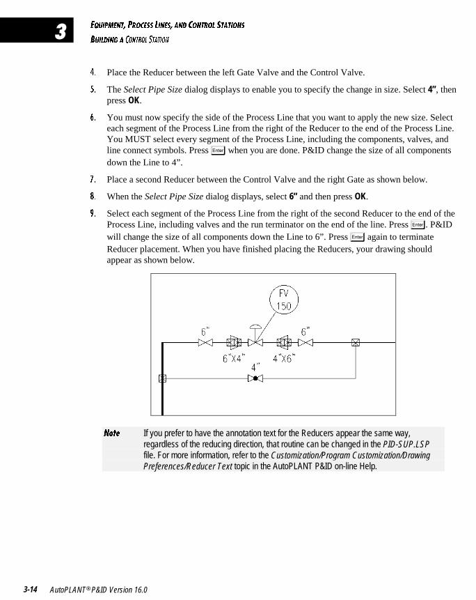
$� Place the Reducer between the left Gate Valve and the Control Valve.
%� The Select Pipe Size dialog displays to enable you to specify the change in size. Select 4”, thenpress OK.
&� You must now specify the side of the Process Line that you want to apply the new size. Selecteach segment of the Process Line from the right of the Reducer to the end of the Process Line.You MUST select every segment of the Process Line, including the components, valves, andline connect symbols. Press � when you are done. P&ID change the size of all componentsdown the Line to 4”.
'� Place a second Reducer between the Control Valve and the right Gate as shown below.
(� When the Select Pipe Size dialog displays, select 6” and then press OK.
)� Select each segment of the Process Line from the right of the second Reducer to the end of theProcess Line, including valves and the run terminator on the end of the line. Press �. P&IDwill change the size of all components down the Line to 6”. Press � again to terminateReducer placement. When you have finished placing the Reducers, your drawing shouldappear as shown below.
>_dU If you prefer to have the annotation text for the Reducers appear the same way,regardless of the reducing direction, that routine can be changed in the PID-SUP.LSPfile. For more information, refer to the Customization/Program Customization/DrawingPreferences/Reducer Text topic in the AutoPLANT P&ID on-line Help.
������������������ ������������
In this chapter, you will learn how to create a Flow Loop, place Flow Valves on aProcess Line, and place Instrumentation in your drawing.
CREATING A FLOW LOOP 4-2
PLACING VALVES 4-8
PLACING INSTRUMENT SYMBOLS 4-10
� � � � � � � � �
�
6<?G <??@C� F1<F5C� 1>4 9>CDBE=5>DC
3B51D9>7 1 6<?G <??@
AutoPLANT® P&ID Version 16.04-2
�
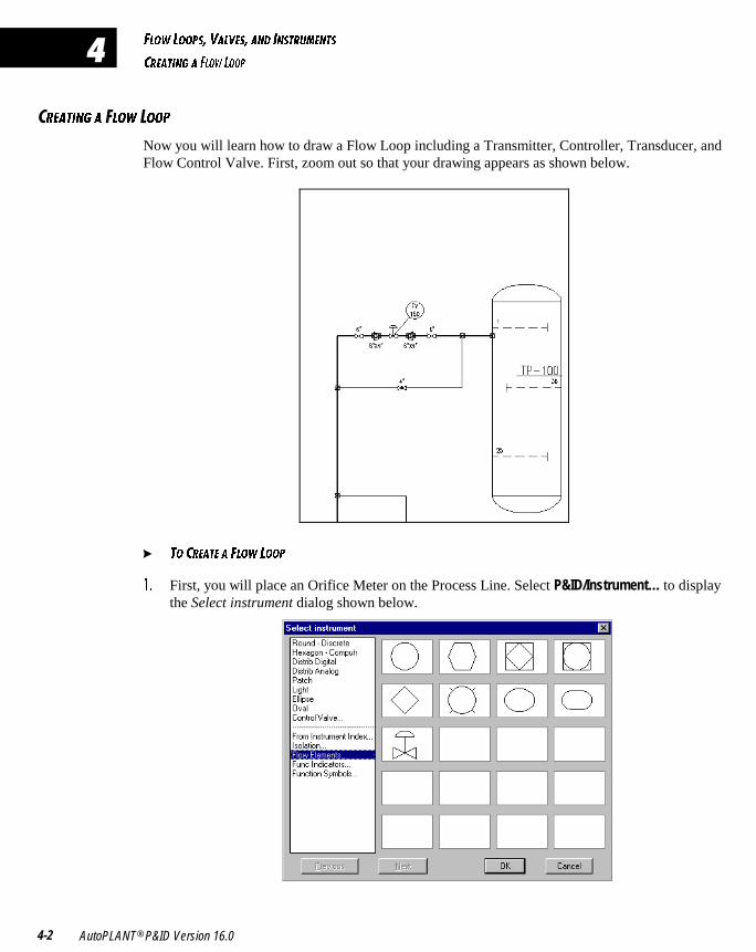
�B51D9>7 1 �<?G �??@
Now you will learn how to draw a Flow Loop including a Transmitter, Controller, Transducer, andFlow Control Valve. First, zoom out so that your drawing appears as shown below.
� D? 3B51D5 1 6<?G <??@
!� First, you will place an Orifice Meter on the Process Line. Select P&ID/Instrument… to displaythe Select instrument dialog shown below.
6<?G <??@C� F1<F5C� 1>4 9>CDBE=5>DC
3B51D9>7 1 6<?G <??@
Tutorial 4-3
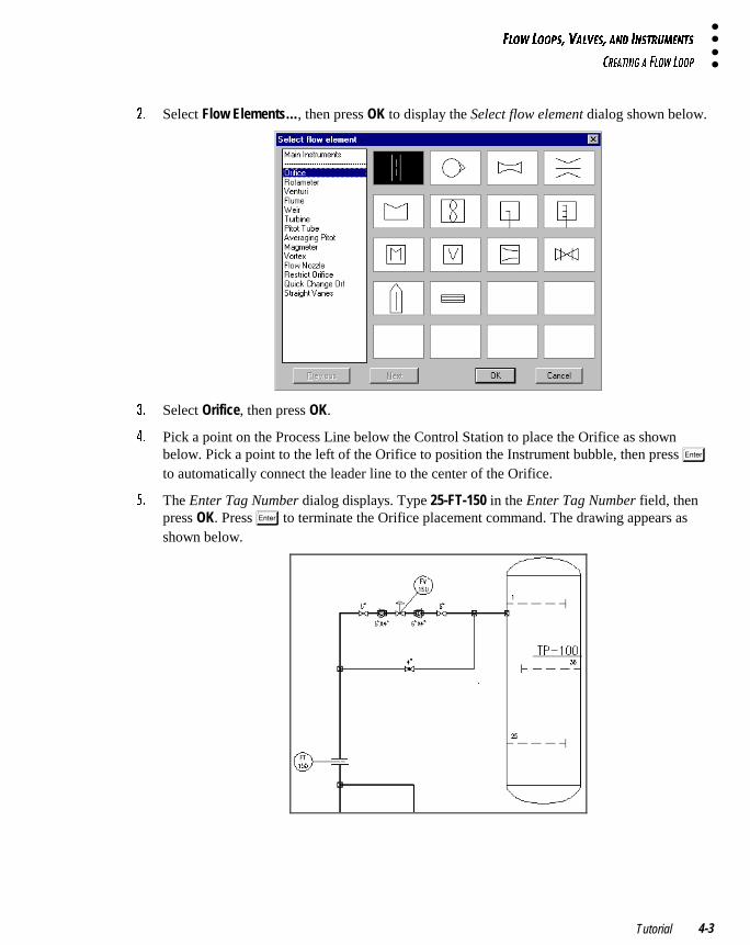
"� Select Flow Elements…, then press OK to display the Select flow element dialog shown below.
#� Select Orifice, then press OK.
$� Pick a point on the Process Line below the Control Station to place the Orifice as shownbelow. Pick a point to the left of the Orifice to position the Instrument bubble, then press �to automatically connect the leader line to the center of the Orifice.
%� The Enter Tag Number dialog displays. Type 25-FT-150 in the Enter Tag Number field, thenpress OK. Press � to terminate the Orifice placement command. The drawing appears asshown below.
6<?G <??@C� F1<F5C� 1>4 9>CDBE=5>DC
3B51D9>7 1 6<?G <??@
AutoPLANT® P&ID Version 16.04-4
�
&� You will now insert a Flow Controller. Select P&ID/Instrument… to display the Select flowelement dialog. Select Main Instruments, then press OK to display the Select instrument dialog.
'� Select Distrib Analog, then press OK.
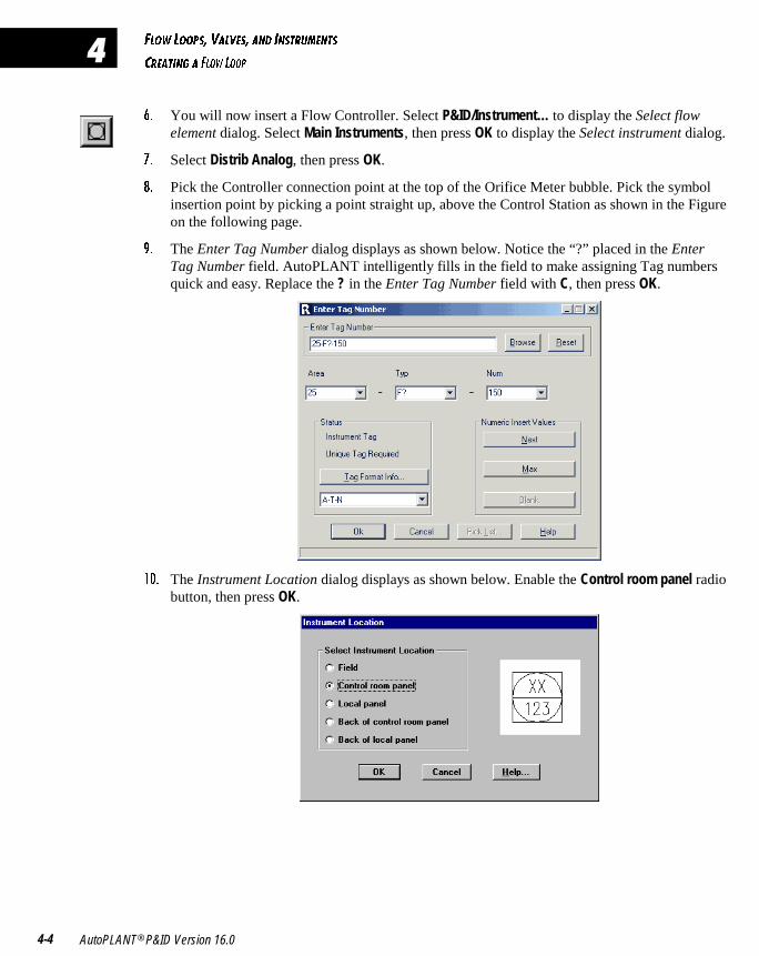
(� Pick the Controller connection point at the top of the Orifice Meter bubble. Pick the symbolinsertion point by picking a point straight up, above the Control Station as shown in the Figureon the following page.
)� The Enter Tag Number dialog displays as shown below. Notice the “?” placed in the EnterTag Number field. AutoPLANT intelligently fills in the field to make assigning Tag numbersquick and easy. Replace the ? in the Enter Tag Number field with C, then press OK.
! � The Instrument Location dialog displays as shown below. Enable the Control room panel radiobutton, then press OK.
6<?G <??@C� F1<F5C� 1>4 9>CDBE=5>DC
3B51D9>7 1 6<?G <??@
Tutorial 4-5
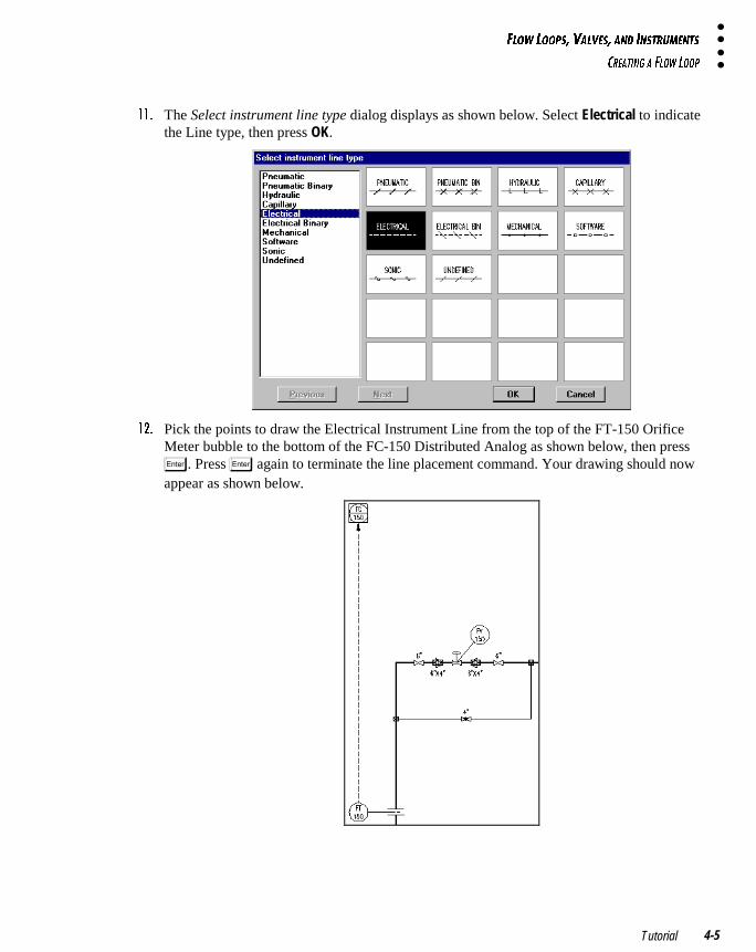
!!� The Select instrument line type dialog displays as shown below. Select Electrical to indicatethe Line type, then press OK.
!"� Pick the points to draw the Electrical Instrument Line from the top of the FT-150 OrificeMeter bubble to the bottom of the FC-150 Distributed Analog as shown below, then press
�. Press � again to terminate the line placement command. Your drawing should nowappear as shown below.
6<?G <??@C� F1<F5C� 1>4 9>CDBE=5>DC
3B51D9>7 1 6<?G <??@
AutoPLANT® P&ID Version 16.04-6
�
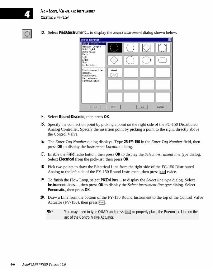
!#� Select P&ID/Instrument… to display the Select instrument dialog shown below.
!$� Select Round-Discrete, then press OK.
!%� Specify the connection point by picking a point on the right side of the FC-150 DistributedAnalog Controller. Specify the insertion point by picking a point to the right, directly abovethe Control Valve.
!&� The Enter Tag Number dialog displays. Type 25-FY-150 in the Enter Tag Number field, thenpress OK to display the Instrument Location dialog.
!'� Enable the Field radio button, then press OK to display the Select instrument line type dialog.Select Electrical from the pick-list, then press OK.
!(� Pick two points to draw the Electrical Line from the right side of the FC-150 DistributedAnalog to the left side of the FY-150 Round Instrument, then press � twice.
!)� To finish the Flow Loop, select P&ID/Lines… to display the Select line type dialog. SelectInstrument Lines…, then press OK to display the Select instrument line type dialog. SelectPneumatic, then press OK.
" � Draw a Line from the bottom of the FY-150 Round Instrument to the top of the Control ValveActuator (FV-150), then press �.
8Y^d You may need to type QUAD and press � to properly place the Pneumatic Line on thearc of the Control Valve Actuator.
6<?G <??@C� F1<F5C� 1>4 9>CDBE=5>DC
3B51D9>7 1 6<?G <??@
Tutorial 4-7
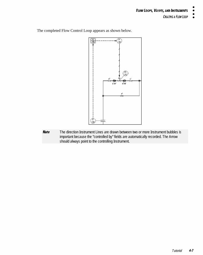
The completed Flow Control Loop appears as shown below.
>_dU The direction Instrument Lines are drawn between two or more Instrument bubbles isimportant because the "controlled by" fields are automatically recorded. The Arrowshould always point to the controlling Instrument.
6<?G <??@C� F1<F5C� 1>4 9>CDBE=5>DC
@<139>7 F1<F5C
AutoPLANT® P&ID Version 16.04-8
�
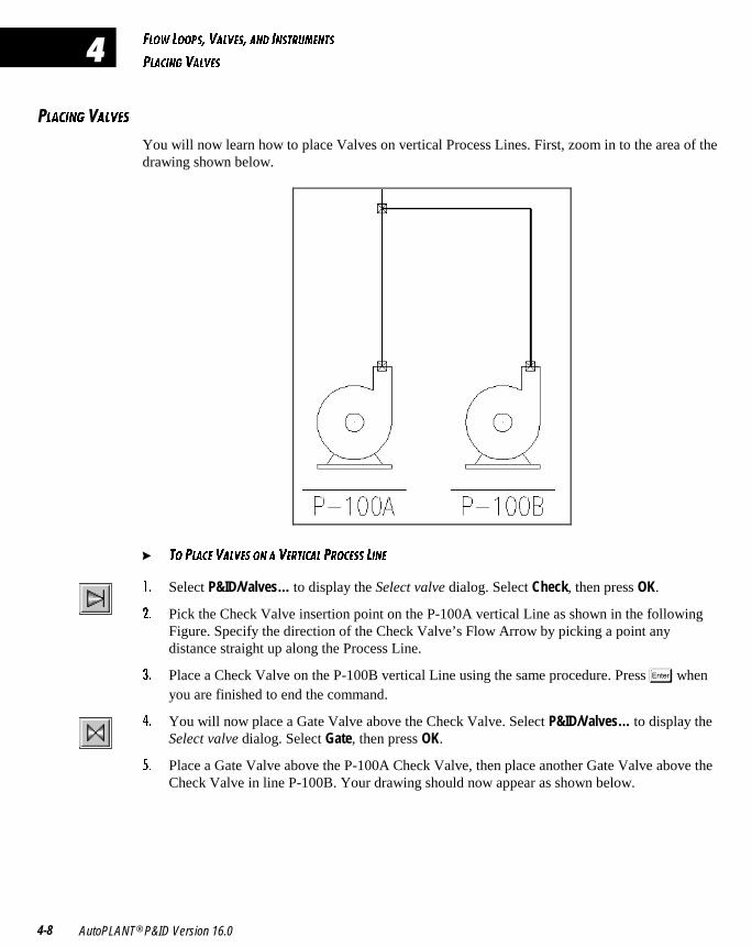
�<139>7 1<F5C
You will now learn how to place Valves on vertical Process Lines. First, zoom in to the area of thedrawing shown below.
� D? @<135 F1<F5C ?> 1 F5BD931< @B?35CC <9>5
!� Select P&ID/Valves… to display the Select valve dialog. Select Check, then press OK.
"� Pick the Check Valve insertion point on the P-100A vertical Line as shown in the followingFigure. Specify the direction of the Check Valve’s Flow Arrow by picking a point anydistance straight up along the Process Line.
#� Place a Check Valve on the P-100B vertical Line using the same procedure. Press � whenyou are finished to end the command.
$� You will now place a Gate Valve above the Check Valve. Select P&ID/Valves… to display theSelect valve dialog. Select Gate, then press OK.
%� Place a Gate Valve above the P-100A Check Valve, then place another Gate Valve above theCheck Valve in line P-100B. Your drawing should now appear as shown below.
6<?G <??@C� F1<F5C� 1>4 9>CDBE=5>DC
@<139>7 F1<F5C
Tutorial 4-9
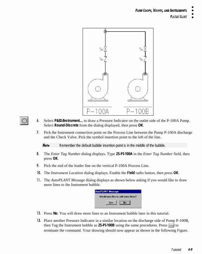
&� Select P&ID/Instrument… to draw a Pressure Indicator on the outlet side of the P-100A Pump.Select Round-Discrete from the dialog displayed, then press OK.
'� Pick the Instrument connection point on the Process Line between the Pump P-100A dischargeand the Check Valve. Pick the symbol insertion point to the left of the line.
>_dU Remember the default bubble insertion point is in the middle of the bubble.
(� The Enter Tag Number dialog displays. Type 25-PI-100A in the Enter Tag Number field, thenpress OK.
)� Pick the end of the leader line on the vertical P-100A Process Line.
! � The Instrument Location dialog displays. Enable the Field radio button, then press OK.
!!� The AutoPLANT Message dialog displays as shown below asking if you would like to drawmore lines to the Instrument bubble.
!"� Press No. You will draw more lines to an Instrument bubble later in this tutorial.
!#� Place another Pressure Indicator in a similar location on the discharge side of Pump P-100B,then Tag the Instrument bubble as 25-PI-100B using the same procedures. Press � toterminate the command. Your drawing should now appear as shown in the following Figure.
6<?G <??@C� F1<F5C� 1>4 9>CDBE=5>DC
@<139>7 9>CDBE=5>D CI=2?<C
AutoPLANT® P&ID Version 16.04-10
�
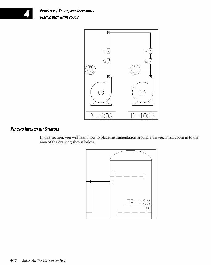
�<139>7 �>CDBE=5>D �I=2?<C
In this section, you will learn how to place Instrumentation around a Tower. First, zoom in to thearea of the drawing shown below.
6<?G <??@C� F1<F5C� 1>4 9>CDBE=5>DC
@<139>7 9>CDBE=5>D CI=2?<C
Tutorial 4-11
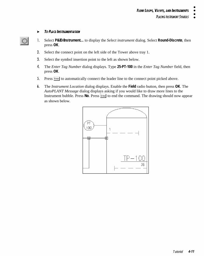
� D? @<135 9>CDBE=5>D1D9?>
!� Select P&ID/Instrument… to display the Select instrument dialog. Select Round-Discrete, thenpress OK.
"� Select the connect point on the left side of the Tower above tray 1.
#� Select the symbol insertion point to the left as shown below.
$� The Enter Tag Number dialog displays. Type 25-PT-100 in the Enter Tag Number field, thenpress OK.
%� Press � to automatically connect the leader line to the connect point picked above.
&� The Instrument Location dialog displays. Enable the Field radio button, then press OK. TheAutoPLANT Message dialog displays asking if you would like to draw more lines to theInstrument bubble. Press No. Press � to end the command. The drawing should now appearas shown below.
6<?G <??@C� F1<F5C� 1>4 9>CDBE=5>DC
@<139>7 9>CDBE=5>D CI=2?<C
AutoPLANT® P&ID Version 16.04-12
�
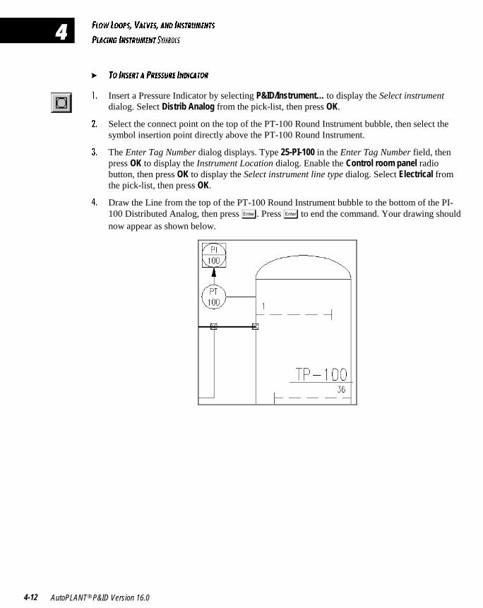
� D? 9>C5BD 1 @B5CCEB5 9>4931D?B
!� Insert a Pressure Indicator by selecting P&ID/Instrument… to display the Select instrumentdialog. Select Distrib Analog from the pick-list, then press OK.
"� Select the connect point on the top of the PT-100 Round Instrument bubble, then select thesymbol insertion point directly above the PT-100 Round Instrument.
#� The Enter Tag Number dialog displays. Type 25-PI-100 in the Enter Tag Number field, thenpress OK to display the Instrument Location dialog. Enable the Control room panel radiobutton, then press OK to display the Select instrument line type dialog. Select Electrical fromthe pick-list, then press OK.
$� Draw the Line from the top of the PT-100 Round Instrument bubble to the bottom of the PI-100 Distributed Analog, then press �. Press � to end the command. Your drawing shouldnow appear as shown below.

���������������������������������������
In this chapter, you will learn how to build an Assembly using the Assembly Manager,place a Vessel skirt on a Vessel, place a Flange on a Vessel Level Gauge andProcess Line, and place To/From and Flow Arrows.
BUILDING AN ASSEMBLY 5-2
PLACING LEVEL GAUGES 5-5
PLACING DRAINS 5-7
PLACING EQUIPMENT TRIM 5-10
PLACING FLANGES 5-11
PLACING ARROWS 5-13
� � � � � � � � �
�
1CC5=2<95C� 5AE9@=5>D DB9=� 6<1>75C� 1>4 1BB?GC
2E9<49>7 1> 1CC5=2<I
AutoPLANT® P&ID Version 16.05-2
�
�E9<49>7 �> �CC5=2<I
In this section, you will build an Assembly from the Instrumentation that you placed in theprevious chapter. You will find the Assembly Manager is one of the most versatile tools of theAutoPLANT P&ID application.
� D? 2E9<4 1> 1CC5=2<I
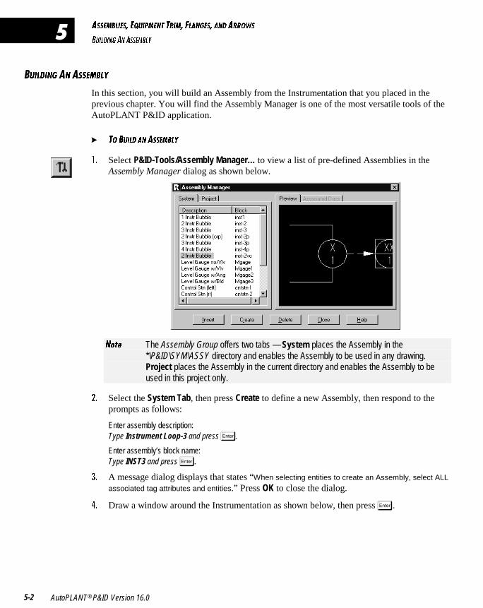
!� Select P&ID-Tools/Assembly Manager… to view a list of pre-defined Assemblies in theAssembly Manager dialog as shown below.
>_dU The Assembly Group offers two tabs — System places the Assembly in the*\P&ID\SYM\ASSY directory and enables the Assembly to be used in any drawing.Project places the Assembly in the current directory and enables the Assembly to beused in this project only.
"� Select the System Tab, then press Create to define a new Assembly, then respond to theprompts as follows:
Enter assembly description: Type Instrument Loop-3 and press �.
Enter assembly’s block name: Type INST3 and press �.
#� A message dialog displays that states “When selecting entities to create an Assembly, select ALL
associated tag attributes and entities.” Press OK to close the dialog.
$� Draw a window around the Instrumentation as shown below, then press �.
1CC5=2<95C� 5AE9@=5>D DB9=� 6<1>75C� 1>4 1BB?GC
2E9<49>7 1> 1CC5=2<I
Tutorial 5-3
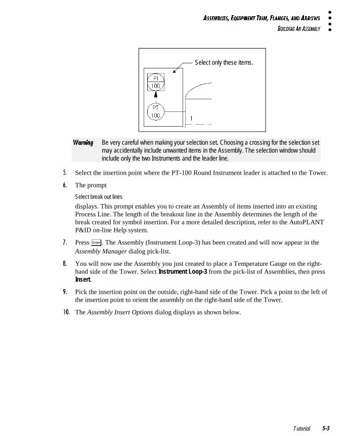
Select only these items.
GQb^Y^W Be very careful when making your selection set. Choosing a crossing for the selection setmay accidentally include unwanted items in the Assembly. The selection window shouldinclude only the two Instruments and the leader line.
%� Select the insertion point where the PT-100 Round Instrument leader is attached to the Tower.
&� The prompt
Select break out lines
displays. This prompt enables you to create an Assembly of items inserted into an existingProcess Line. The length of the breakout line in the Assembly determines the length of thebreak created for symbol insertion. For a more detailed description, refer to the AutoPLANTP&ID on-line Help system.
'� Press �. The Assembly (Instrument Loop-3) has been created and will now appear in theAssembly Manager dialog pick-list.
(� You will now use the Assembly you just created to place a Temperature Gauge on the right-hand side of the Tower. Select Instrument Loop-3 from the pick-list of Assemblies, then pressInsert.
)� Pick the insertion point on the outside, right-hand side of the Tower. Pick a point to the left ofthe insertion point to orient the assembly on the right-hand side of the Tower.
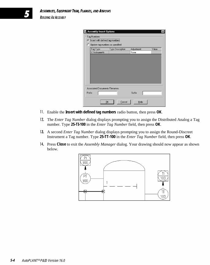
! � The Assembly Insert Options dialog displays as shown below.
1CC5=2<95C� 5AE9@=5>D DB9=� 6<1>75C� 1>4 1BB?GC
2E9<49>7 1> 1CC5=2<I
AutoPLANT® P&ID Version 16.05-4
�
!!� Enable the Insert with defined tag numbers radio button, then press OK.
!"� The Enter Tag Number dialog displays prompting you to assign the Distributed Analog a Tagnumber. Type 25-TI-100 in the Enter Tag Number field, then press OK.
!#� A second Enter Tag Number dialog displays prompting you to assign the Round-DiscreetInstrument a Tag number. Type 25-TT-100 in the Enter Tag Number field, then press OK.
!$� Press Close to exit the Assembly Manager dialog. Your drawing should now appear as shownbelow.
1CC5=2<95C� 5AE9@=5>D DB9=� 6<1>75C� 1>4 1BB?GC
@<139>7 <5F5< 71E75C
Tutorial 5-5
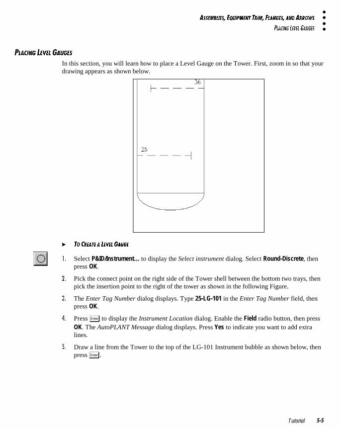
�<139>7 �5F5< �1E75C
In this section, you will learn how to place a Level Gauge on the Tower. First, zoom in so that yourdrawing appears as shown below.
� D? 3B51D5 1 <5F5< 71E75
!� Select P&ID/Instrument… to display the Select instrument dialog. Select Round-Discrete, thenpress OK.
"� Pick the connect point on the right side of the Tower shell between the bottom two trays, thenpick the insertion point to the right of the tower as shown in the following Figure.
#� The Enter Tag Number dialog displays. Type 25-LG-101 in the Enter Tag Number field, thenpress OK.
$� Press � to display the Instrument Location dialog. Enable the Field radio button, then pressOK. The AutoPLANT Message dialog displays. Press Yes to indicate you want to add extralines.
%� Draw a line from the Tower to the top of the LG-101 Instrument bubble as shown below, thenpress �.
1CC5=2<95C� 5AE9@=5>D DB9=� 6<1>75C� 1>4 1BB?GC
@<139>7 <5F5< 71E75C
AutoPLANT® P&ID Version 16.05-6
�
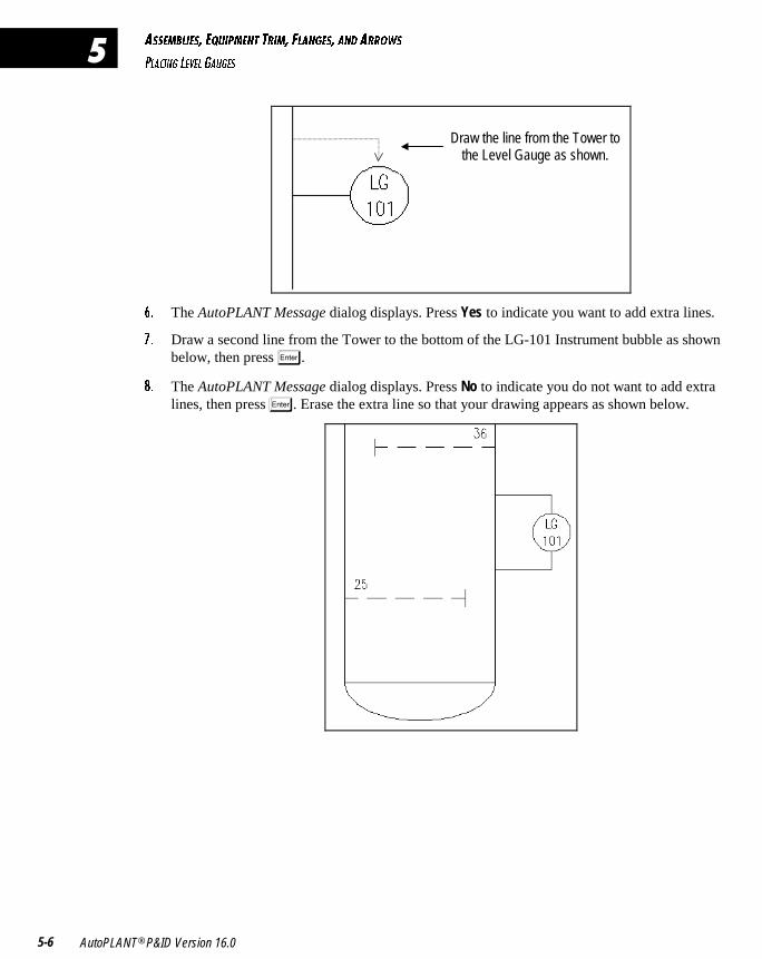
Draw the line from the Tower to the Level Gauge as shown.
&� The AutoPLANT Message dialog displays. Press Yes to indicate you want to add extra lines.
'� Draw a second line from the Tower to the bottom of the LG-101 Instrument bubble as shownbelow, then press �.
(� The AutoPLANT Message dialog displays. Press No to indicate you do not want to add extralines, then press �. Erase the extra line so that your drawing appears as shown below.
1CC5=2<95C� 5AE9@=5>D DB9=� 6<1>75C� 1>4 1BB?GC
@<139>7 4B19>C
Tutorial 5-7
�<139>7 �B19>C
� D? @<135 1 4B19>
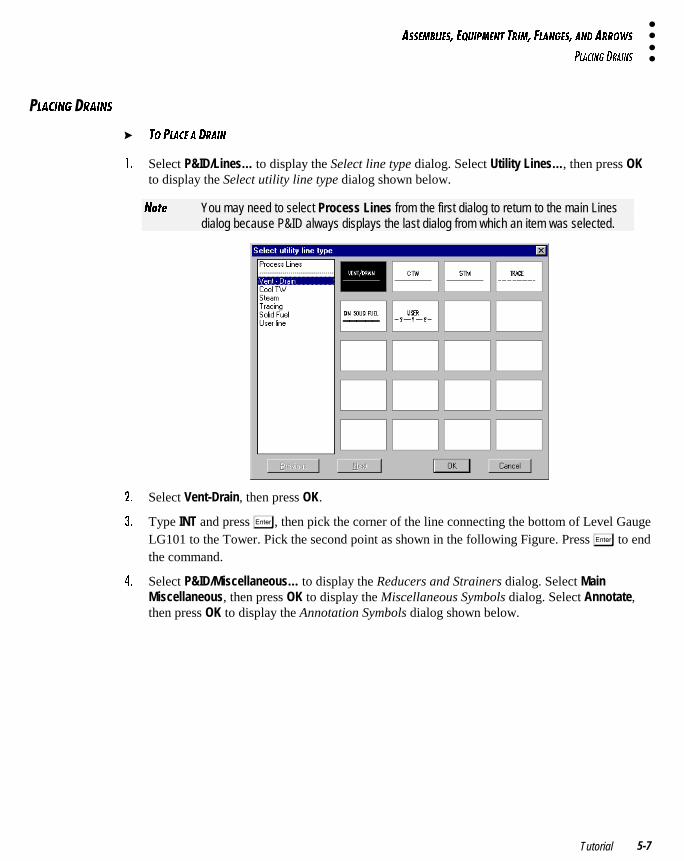
!� Select P&ID/Lines… to display the Select line type dialog. Select Utility Lines…, then press OKto display the Select utility line type dialog shown below.
>_dU You may need to select Process Lines from the first dialog to return to the main Linesdialog because P&ID always displays the last dialog from which an item was selected.
"� Select Vent-Drain, then press OK.
#� Type INT and press �, then pick the corner of the line connecting the bottom of Level GaugeLG101 to the Tower. Pick the second point as shown in the following Figure. Press � to endthe command.
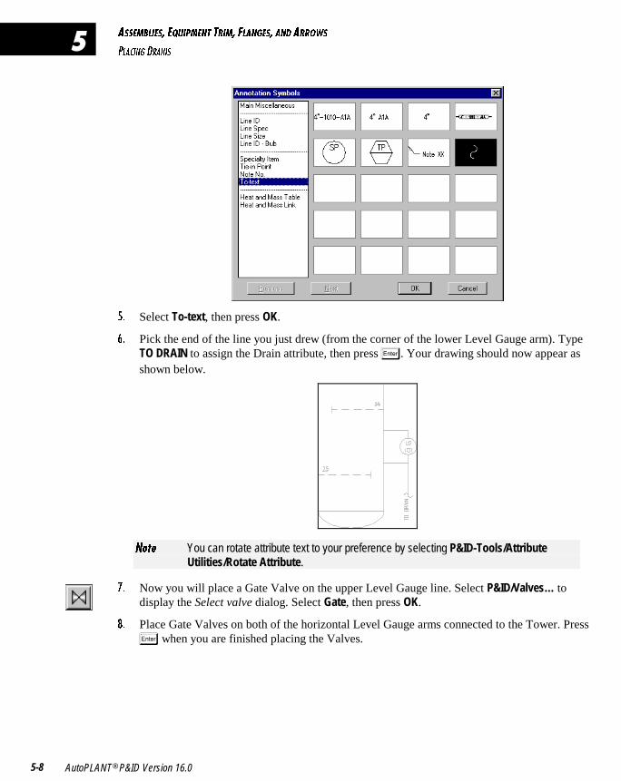
$� Select P&ID/Miscellaneous… to display the Reducers and Strainers dialog. Select MainMiscellaneous, then press OK to display the Miscellaneous Symbols dialog. Select Annotate,then press OK to display the Annotation Symbols dialog shown below.
1CC5=2<95C� 5AE9@=5>D DB9=� 6<1>75C� 1>4 1BB?GC
@<139>7 4B19>C
AutoPLANT® P&ID Version 16.05-8
�
%� Select To-text, then press OK.
&� Pick the end of the line you just drew (from the corner of the lower Level Gauge arm). TypeTO DRAIN to assign the Drain attribute, then press �. Your drawing should now appear asshown below.
>_dU You can rotate attribute text to your preference by selecting P&ID-Tools/AttributeUtilities/Rotate Attribute.
'� Now you will place a Gate Valve on the upper Level Gauge line. Select P&ID/Valves… todisplay the Select valve dialog. Select Gate, then press OK.
(� Place Gate Valves on both of the horizontal Level Gauge arms connected to the Tower. Press
� when you are finished placing the Valves.
1CC5=2<95C� 5AE9@=5>D DB9=� 6<1>75C� 1>4 1BB?GC
@<139>7 4B19>C
Tutorial 5-9
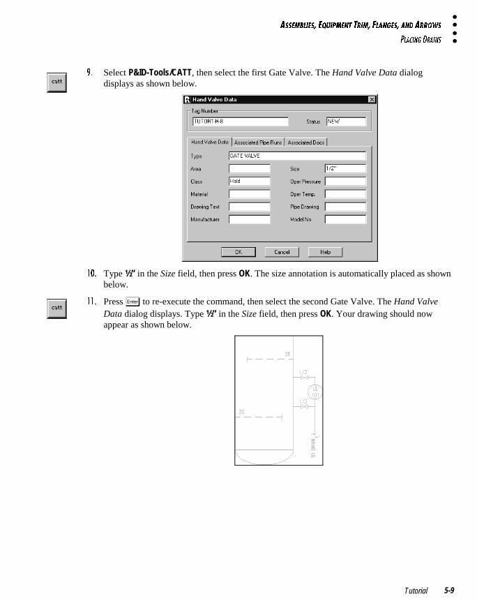
)� Select P&ID-Tools/CATT, then select the first Gate Valve. The Hand Valve Data dialogdisplays as shown below.
! � Type ½” in the Size field, then press OK. The size annotation is automatically placed as shownbelow.
!!� Press � to re-execute the command, then select the second Gate Valve. The Hand ValveData dialog displays. Type ½” in the Size field, then press OK. Your drawing should nowappear as shown below.
1CC5=2<95C� 5AE9@=5>D DB9=� 6<1>75C� 1>4 1BB?GC
@<139>7 5AE9@=5>D DB9=
AutoPLANT® P&ID Version 16.05-10
�
�<139>7 �AE9@=5>D �B9=
In this section, you will learn how to place a Vessel skirt.
� D? @<135 5AE9@=5>D DB9=
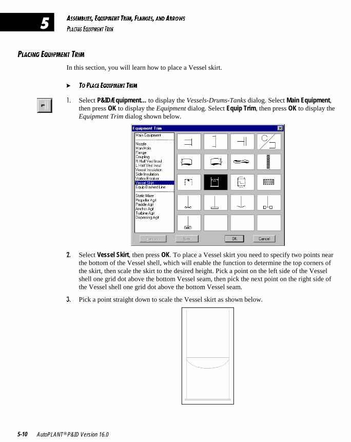
!� Select P&ID/Equipment… to display the Vessels-Drums-Tanks dialog. Select Main Equipment,then press OK to display the Equipment dialog. Select Equip Trim, then press OK to display theEquipment Trim dialog shown below.
"� Select Vessel Skirt, then press OK. To place a Vessel skirt you need to specify two points nearthe bottom of the Vessel shell, which will enable the function to determine the top corners ofthe skirt, then scale the skirt to the desired height. Pick a point on the left side of the Vesselshell one grid dot above the bottom Vessel seam, then pick the next point on the right side ofthe Vessel shell one grid dot above the bottom Vessel seam.
#� Pick a point straight down to scale the Vessel skirt as shown below.
1CC5=2<95C� 5AE9@=5>D DB9=� 6<1>75C� 1>4 1BB?GC
@<139>7 6<1>75C
Tutorial 5-11
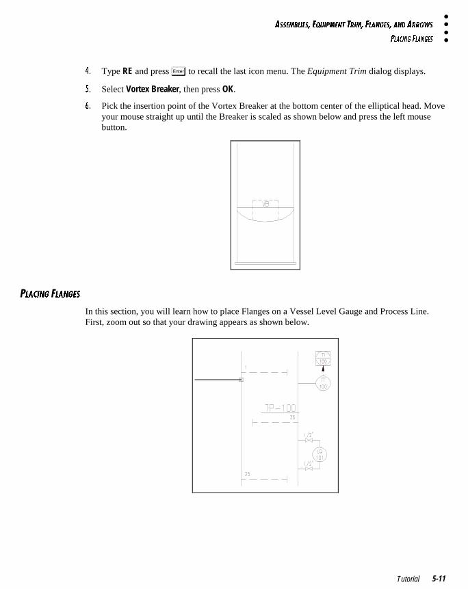
$� Type RE and press � to recall the last icon menu. The Equipment Trim dialog displays.
%� Select Vortex Breaker, then press OK.
&� Pick the insertion point of the Vortex Breaker at the bottom center of the elliptical head. Moveyour mouse straight up until the Breaker is scaled as shown below and press the left mousebutton.
�<139>7 �<1>75C
In this section, you will learn how to place Flanges on a Vessel Level Gauge and Process Line.First, zoom out so that your drawing appears as shown below.
1CC5=2<95C� 5AE9@=5>D DB9=� 6<1>75C� 1>4 1BB?GC
@<139>7 6<1>75C
AutoPLANT® P&ID Version 16.05-12
�
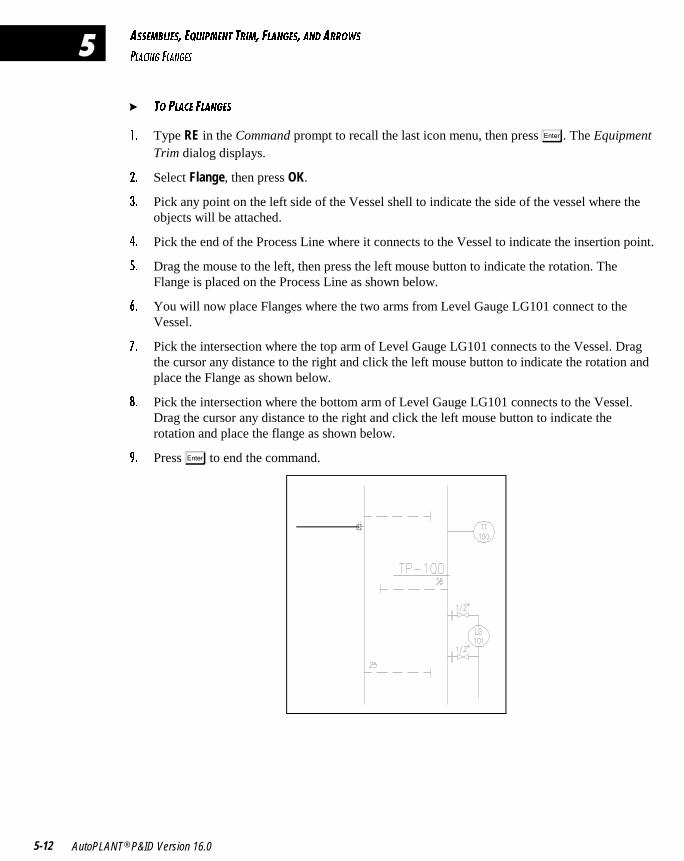
� D? @<135 6<1>75C
!� Type RE in the Command prompt to recall the last icon menu, then press �. The EquipmentTrim dialog displays.
"� Select Flange, then press OK.
#� Pick any point on the left side of the Vessel shell to indicate the side of the vessel where theobjects will be attached.
$� Pick the end of the Process Line where it connects to the Vessel to indicate the insertion point.
%� Drag the mouse to the left, then press the left mouse button to indicate the rotation. TheFlange is placed on the Process Line as shown below.
&� You will now place Flanges where the two arms from Level Gauge LG101 connect to theVessel.
'� Pick the intersection where the top arm of Level Gauge LG101 connects to the Vessel. Dragthe cursor any distance to the right and click the left mouse button to indicate the rotation andplace the Flange as shown below.
(� Pick the intersection where the bottom arm of Level Gauge LG101 connects to the Vessel.Drag the cursor any distance to the right and click the left mouse button to indicate therotation and place the flange as shown below.
)� Press � to end the command.
1CC5=2<95C� 5AE9@=5>D DB9=� 6<1>75C� 1>4 1BB?GC
@<139>7 1BB?GC
Tutorial 5-13
�<139>7 �BB?GC
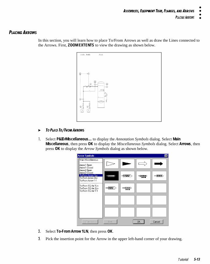
In this section, you will learn how to place To/From Arrows as well as draw the Lines connected tothe Arrows. First, ZOOM EXTENTS to view the drawing as shown below.
� D? @<135 D?�6B?= 1BB?GC
!� Select P&ID/Miscellaneous… to display the Annotation Symbols dialog. Select MainMiscellaneous, then press OK to display the Miscellaneous Symbols dialog. Select Arrows, thenpress OK to display the Arrow Symbols dialog as shown below.
"� Select To-From Arrow 1LN, then press OK.
#� Pick the insertion point for the Arrow in the upper left-hand corner of your drawing.
1CC5=2<95C� 5AE9@=5>D DB9=� 6<1>75C� 1>4 1BB?GC
@<139>7 1BB?GC
AutoPLANT® P&ID Version 16.05-14
�
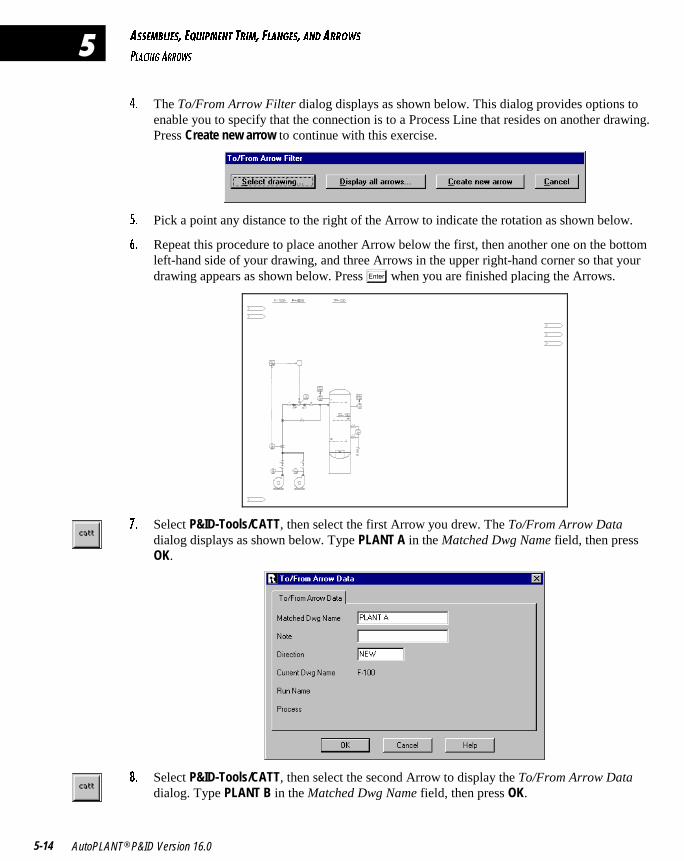
$� The To/From Arrow Filter dialog displays as shown below. This dialog provides options toenable you to specify that the connection is to a Process Line that resides on another drawing.Press Create new arrow to continue with this exercise.
%� Pick a point any distance to the right of the Arrow to indicate the rotation as shown below.
&� Repeat this procedure to place another Arrow below the first, then another one on the bottomleft-hand side of your drawing, and three Arrows in the upper right-hand corner so that yourdrawing appears as shown below. Press � when you are finished placing the Arrows.
'� Select P&ID-Tools/CATT, then select the first Arrow you drew. The To/From Arrow Datadialog displays as shown below. Type PLANT A in the Matched Dwg Name field, then pressOK.
(� Select P&ID-Tools/CATT, then select the second Arrow to display the To/From Arrow Datadialog. Type PLANT B in the Matched Dwg Name field, then press OK.
1CC5=2<95C� 5AE9@=5>D DB9=� 6<1>75C� 1>4 1BB?GC
@<139>7 1BB?GC
Tutorial 5-15
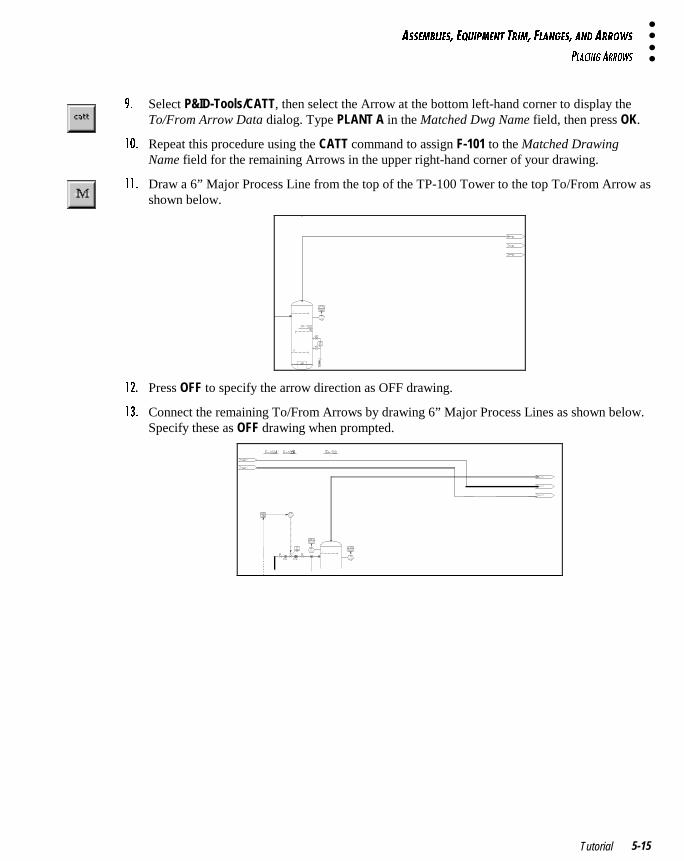
)� Select P&ID-Tools/CATT, then select the Arrow at the bottom left-hand corner to display theTo/From Arrow Data dialog. Type PLANT A in the Matched Dwg Name field, then press OK.
! � Repeat this procedure using the CATT command to assign F-101 to the Matched DrawingName field for the remaining Arrows in the upper right-hand corner of your drawing.
!!� Draw a 6” Major Process Line from the top of the TP-100 Tower to the top To/From Arrow asshown below.
!"� Press OFF to specify the arrow direction as OFF drawing.
!#� Connect the remaining To/From Arrows by drawing 6” Major Process Lines as shown below.Specify these as OFF drawing when prompted.
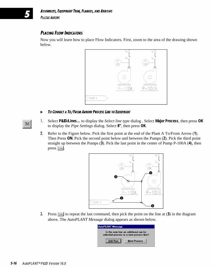
1CC5=2<95C� 5AE9@=5>D DB9=� 6<1>75C� 1>4 1BB?GC
@<139>7 1BB?GC
AutoPLANT® P&ID Version 16.05-16
�
�<139>7 <?G �>4931D?BC
Now you will learn how to place Flow Indicators. First, zoom to the area of the drawing shownbelow.
� D? 3?>>53D 1 D?�6B?= 1BB?G @B?35CC <9>5 D? 5AE9@=5>D
!� Select P&ID/Lines… to display the Select line type dialog . Select Major Process, then press OKto display the Pipe Settings dialog. Select 8”, then press OK.
"� Refer to the Figure below. Pick the first point at the end of the Plant A To/From Arrow (1).Then Press ON. Pick the second point below and between the Pumps (2). Pick the third pointstraight up between the Pumps (3). Pick the last point in the center of Pump P-100A (4), thenpress �.
3
4
2
1
#� Press � to repeat the last command, then pick the point on the line at (3) in the diagramabove. The AutoPLANT Message dialog appears as shown below.
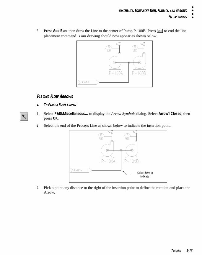
1CC5=2<95C� 5AE9@=5>D DB9=� 6<1>75C� 1>4 1BB?GC
@<139>7 1BB?GC
Tutorial 5-17
$� Press Add Run, then draw the Line to the center of Pump P-100B. Press � to end the lineplacement command. Your drawing should now appear as shown below.
�<139>7 <?G �BB?GC
� D? @<135 1 6<?G 1BB?G
!� Select P&ID/Miscellaneous… to display the Arrow Symbols dialog. Select Arrow1 Closed, thenpress OK.
"� Select the end of the Process Line as shown below to indicate the insertion point.
Select here toindicate
#� Pick a point any distance to the right of the insertion point to define the rotation and place theArrow.
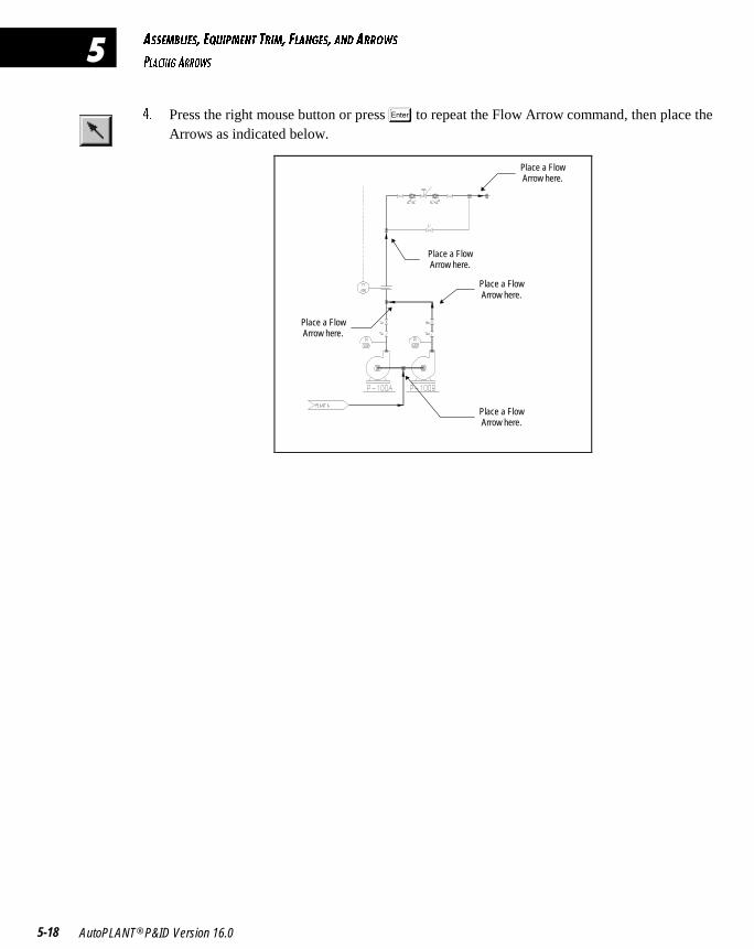
1CC5=2<95C� 5AE9@=5>D DB9=� 6<1>75C� 1>4 1BB?GC
@<139>7 1BB?GC
AutoPLANT® P&ID Version 16.05-18
�
$� Press the right mouse button or press � to repeat the Flow Arrow command, then place theArrows as indicated below.
Place a FlowArrow here.
Place a FlowArrow here.
Place a FlowArrow here.
Place a FlowArrow here.
Place a FlowArrow here.
��� ����������������������������
In this chapter, you will learn how to use the Process Line Manager to reassign aPipe Run to an existing Process Line. You will also learn how to remove and replacea Valve, change and toggle attributes, move secondary Equipment Tags, and breaka Process Line intersection.
USING PROCESS MANAGER TO REASSIGN A PIPE RUN 6-2
EDITING FEATURES 6-5
� � � � � � � � �
�
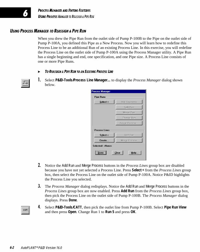
@B?35CC=1>175B 1>4 549D9>7 651DEB5C
EC9>7 @B?35CC=1>175B D? B51CC97> 1 @9@5 BE>
AutoPLANT® P&ID Version 16.06-2
�
�C9>7 �B?35CC�1>175B D? �51CC97> 1 �9@5 �E>
When you drew the Pipe Run from the outlet side of Pump P-100B to the Pipe on the outlet side ofPump P-100A, you defined this Pipe as a New Process. Now you will learn how to redefine thisProcess Line to be an additional Run of an existing Process Line. In this exercise, you will redefinethe Process Line on the outlet side of Pump P-100A using the Process Manager utility. A Pipe Runhas a single beginning and end, one specification, and one Pipe size. A Process Line consists ofone or more Pipe Runs.
� D? B51CC97> 1 @9@5 BE> D? 1> 5H9CD9>7 @B?35CC <9>5
!� Select P&ID-Tools/Process Line Manager… to display the Process Manager dialog shownbelow.
"� Notice the Add Run and Merge Process buttons in the Process Lines group box are disabledbecause you have not yet selected a Process Line. Press Select < from the Process Lines groupbox, then select the Process Line on the outlet side of Pump P-100A. Notice P&ID highlightsthe Process Line you selected.
#� The Process Manager dialog redisplays. Notice the Add Run and Merge Process buttons in theProcess Lines group box are now enabled. Press Add Run from the Process Lines group box,then pick the Process Line on the outlet side of Pump P-100B. The Process Manager dialogdisplays. Press Done.
$� Select P&ID-Tools/CATT, then pick the outlet line from Pump P-100B. Select Pipe Run Viewand then press Open. Change Run 1 to Run 5 and press OK.
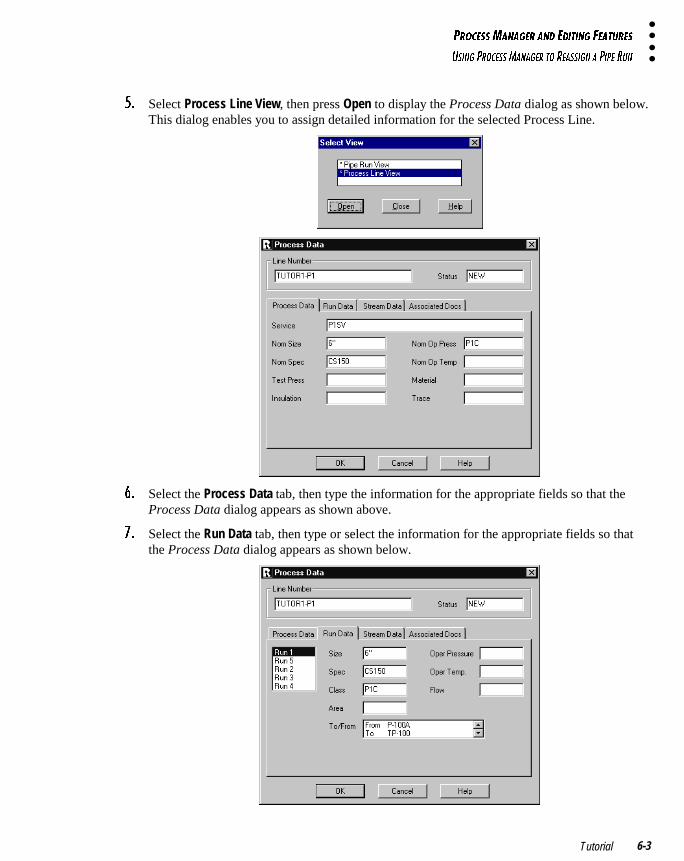
@B?35CC=1>175B 1>4 549D9>7 651DEB5C
EC9>7 @B?35CC=1>175B D? B51CC97> 1 @9@5 BE>
Tutorial 6-3
%� Select Process Line View, then press Open to display the Process Data dialog as shown below.This dialog enables you to assign detailed information for the selected Process Line.
&� Select the Process Data tab, then type the information for the appropriate fields so that theProcess Data dialog appears as shown above.
'� Select the Run Data tab, then type or select the information for the appropriate fields so thatthe Process Data dialog appears as shown below.
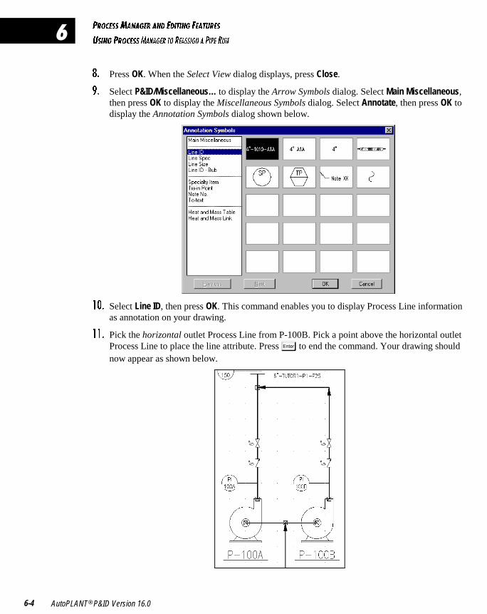
@B?35CC=1>175B 1>4 549D9>7 651DEB5C
EC9>7 @B?35CC=1>175B D? B51CC97> 1 @9@5 BE>
AutoPLANT® P&ID Version 16.06-4
�
(� Press OK. When the Select View dialog displays, press Close.
)� Select P&ID/Miscellaneous… to display the Arrow Symbols dialog. Select Main Miscellaneous,then press OK to display the Miscellaneous Symbols dialog. Select Annotate, then press OK todisplay the Annotation Symbols dialog shown below.
! � Select Line ID, then press OK. This command enables you to display Process Line informationas annotation on your drawing.
!!� Pick the horizontal outlet Process Line from P-100B. Pick a point above the horizontal outletProcess Line to place the line attribute. Press � to end the command. Your drawing shouldnow appear as shown below.
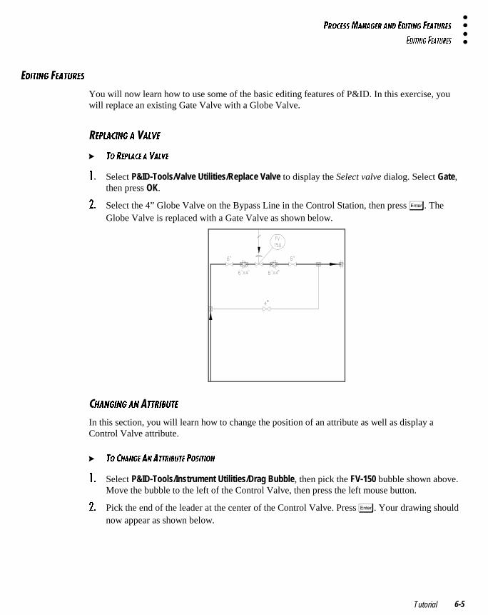
@B?35CC=1>175B 1>4 549D9>7 651DEB5C
549D9>7 651DEB5C
Tutorial 6-5
�49D9>7 �51DEB5C
You will now learn how to use some of the basic editing features of P&ID. In this exercise, youwill replace an existing Gate Valve with a Globe Valve.
�5@<139>7 1 1<F5
� D? B5@<135 1 F1<F5
!� Select P&ID-Tools/Valve Utilities/Replace Valve to display the Select valve dialog. Select Gate,then press OK.
"� Select the 4” Globe Valve on the Bypass Line in the Control Station, then press �. TheGlobe Valve is replaced with a Gate Valve as shown below.
�81>79>7 1> �DDB92ED5
In this section, you will learn how to change the position of an attribute as well as display aControl Valve attribute.
� D? 381>75 1> 1DDB92ED5 @?C9D9?>
!� Select P&ID-Tools/Instrument Utilities/Drag Bubble, then pick the FV-150 bubble shown above.Move the bubble to the left of the Control Valve, then press the left mouse button.
"� Pick the end of the leader at the center of the Control Valve. Press �. Your drawing shouldnow appear as shown below.
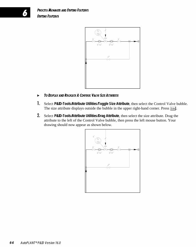
@B?35CC=1>175B 1>4 549D9>7 651DEB5C
549D9>7 651DEB5C
AutoPLANT® P&ID Version 16.06-6
�
� D? 49C@<1I 1>4 B5<?31D5 1 3?>DB?< F1<F5 C9J5 1DDB92ED5
!� Select P&ID-Tools/Attribute Utilities/Toggle Size Attribute, then select the Control Valve bubble.The size attribute displays outside the bubble in the upper right-hand corner. Press �.
"� Select P&ID-Tools/Attribute Utilities/Drag Attribute, then select the size attribute. Drag theattribute to the left of the Control Valve bubble, then press the left mouse button. Yourdrawing should now appear as shown below.
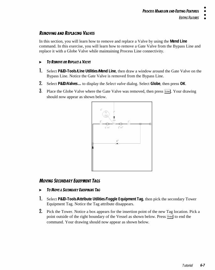
@B?35CC=1>175B 1>4 549D9>7 651DEB5C
549D9>7 651DEB5C
Tutorial 6-7
�5=?F9>7 1>4 �5@<139>7 1<F5C
In this section, you will learn how to remove and replace a Valve by using the Mend Linecommand. In this exercise, you will learn how to remove a Gate Valve from the Bypass Line andreplace it with a Globe Valve while maintaining Process Line connectivity.
� D? B5=?F5 ?B B5@<135 1 F1<F5
!� Select P&ID-Tools/Line Utilities/Mend Line, then draw a window around the Gate Valve on theBypass Line. Notice the Gate Valve is removed from the Bypass Line.
"� Select P&ID/Valves… to display the Select valve dialog. Select Globe, then press OK.
#� Place the Globe Valve where the Gate Valve was removed, then press �. Your drawingshould now appear as shown below.
?F9>7 �53?>41BI �AE9@=5>D �17C
� D?=?F5 1 C53?>41BI 5AE9@=5>D D17
!� Select P&ID-Tools/Attribute Utilities/Toggle Equipment Tag, then pick the secondary TowerEquipment Tag. Notice the Tag attribute disappears.
"� Pick the Tower. Notice a box appears for the insertion point of the new Tag location. Pick apoint outside of the right boundary of the Vessel as shown below. Press � to end thecommand. Your drawing should now appear as shown below.
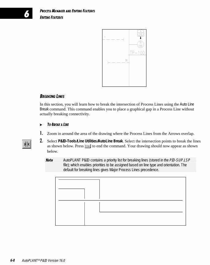
@B?35CC=1>175B 1>4 549D9>7 651DEB5C
549D9>7 651DEB5C
AutoPLANT® P&ID Version 16.06-8
�
�B51;9>7 9>5C
In this section, you will learn how to break the intersection of Process Lines using the Auto LineBreak command. This command enables you to place a graphical gap in a Process Line withoutactually breaking connectivity.
� D? 2B51; 1 <9>5
!� Zoom in around the area of the drawing where the Process Lines from the Arrows overlap.
"� Select P&ID-Tools/Line Utilities/AutoLine Break. Select the intersection points to break the linesas shown below. Press � to end the command. Your drawing should now appear as shownbelow.
>_dU AutoPLANT P&ID contains a priority list for breaking lines (stored in the PID-SUP.LSPfile); which enables priorities to be assigned based on line type and orientation. Thedefault for breaking lines gives Major Process Lines precedence.

������������������ ����������
This tutorial introduces you to some of the advanced features and functions of theAutoPLANT P&ID application. This section also provides exercises to operate in theExpert Mode of operation.
CHAPTER 7: EXPERT MODE, TO/FROM ARROWS, CONSISTENCY
CHECKS, AND EXTERNAL FILES
CHAPTER 8: PSVS, ASSEMBLIES, AND EXCHANGE DRAWINGS
� � � � � �
��
����������������������������� ������� �� �� ���
�����������������
This section of the AutoPLANT P&ID tutorial explores the advanced featuresavailable in a project environment and familiarizes you with the Expert Mode ofoperation. During this chapter, you will match To/From Arrows, perform a consistencycheck, and associate documents with a component.
ENABLING EXPERT MODE 7-2
MATCHING TO/FROM ARROWS 7-2
RUNNING CONSISTENCY CHECKS 7-3
LINKING EXTERNAL FILES 7-5
� � � � � � � � �
�
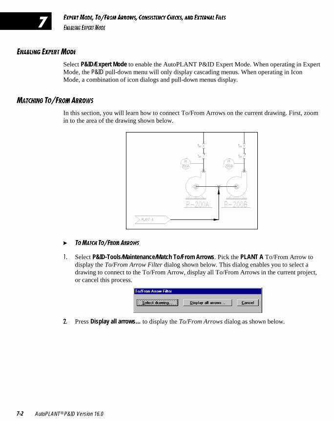
5H@5BD=?45� D?�6B?= 1BB?GC� 3?>C9CD5>3I 3853;C� 1>4 5HD5B>1< 69<5C
5>12<9>7 5H@5BD=?45
AutoPLANT® P&ID Version 16.07-2
�
�>12<9>7 �H@5BD�?45
Select P&ID/Expert Mode to enable the AutoPLANT P&ID Expert Mode. When operating in ExpertMode, the P&ID pull-down menu will only display cascading menus. When operating in IconMode, a combination of icon dialogs and pull-down menus display.
�1D389>7 �?��B?= �BB?GC
In this section, you will learn how to connect To/From Arrows on the current drawing. First, zoomin to the area of the drawing shown below.
� �?�1D38 �?��B?= �BB?GC
!� Select P&ID-Tools/Maintenance/Match To/From Arrows. Pick the PLANT A To/From Arrow todisplay the To/From Arrow Filter dialog shown below. This dialog enables you to select adrawing to connect to the To/From Arrow, display all To/From Arrows in the current project,or cancel this process.
"� Press Display all arrows… to display the To/From Arrows dialog as shown below.
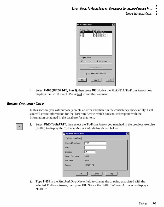
5H@5BD=?45� D?�6B?= 1BB?GC� 3?>C9CD5>3I 3853;C� 1>4 5HD5B>1< 69<5C
BE>>9>7 3?>C9CD5>3I 3853;C
Tutorial 7-3
#� Select F-100 (TUTOR1-P6, Run 1), then press OK. Notice the PLANT A To/From Arrow nowdisplays the F-100 match. Press � to end the command.
�E>>9>7 ?>C9CD5>3I 853;C
In this section, you will purposely create an error and then run the consistency check utility. Firstyou will create information for the To/From Arrow, which does not correspond with theinformation contained in the database for that item.
!� Select P&ID-Tools/CATT, then select the To/From Arrow you matched in the previous exercise(F-100) to display the To/From Arrow Data dialog shown below.
"� Type F-101 in the Matched Dwg Name field to change the drawing associated with theselected To/From Arrow, then press OK. Notice the F-100 To/From Arrow now displays“F-101.”
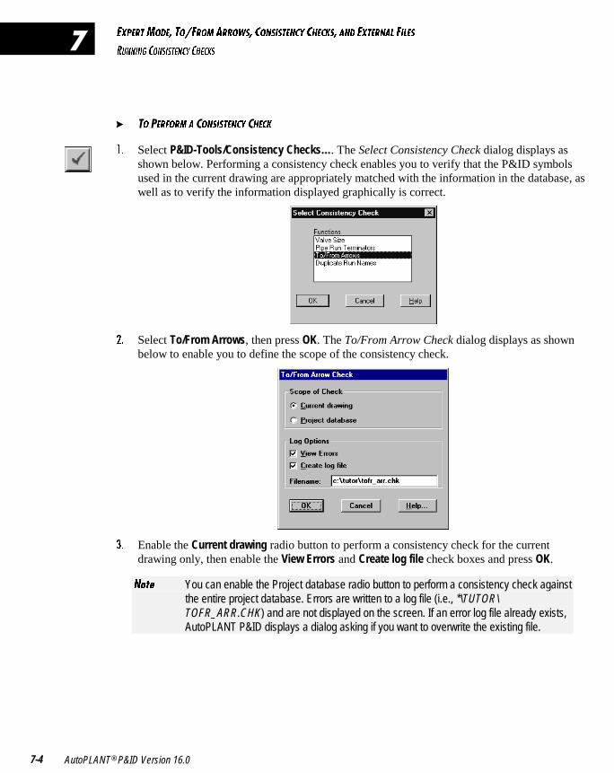
5H@5BD=?45� D?�6B?= 1BB?GC� 3?>C9CD5>3I 3853;C� 1>4 5HD5B>1< 69<5C
BE>>9>7 3?>C9CD5>3I 3853;C
AutoPLANT® P&ID Version 16.07-4
�
� �? �5B6?B= 1 ?>C9CD5>3I 853;
!� Select P&ID-Tools/Consistency Checks…. The Select Consistency Check dialog displays asshown below. Performing a consistency check enables you to verify that the P&ID symbolsused in the current drawing are appropriately matched with the information in the database, aswell as to verify the information displayed graphically is correct.
"� Select To/From Arrows, then press OK. The To/From Arrow Check dialog displays as shownbelow to enable you to define the scope of the consistency check.
#� Enable the Current drawing radio button to perform a consistency check for the currentdrawing only, then enable the View Errors and Create log file check boxes and press OK.
>_dU You can enable the Project database radio button to perform a consistency check againstthe entire project database. Errors are written to a log file (i.e., *\TUTOR\TOFR_ARR.CHK) and are not displayed on the screen. If an error log file already exists,AutoPLANT P&ID displays a dialog asking if you want to overwrite the existing file.
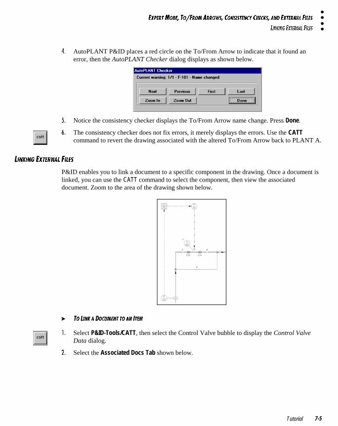
5H@5BD=?45� D?�6B?= 1BB?GC� 3?>C9CD5>3I 3853;C� 1>4 5HD5B>1< 69<5C
<9>;9>7 5HD5B>1< 69<5C
Tutorial 7-5
$� AutoPLANT P&ID places a red circle on the To/From Arrow to indicate that it found anerror, then the AutoPLANT Checker dialog displays as shown below.
%� Notice the consistency checker displays the To/From Arrow name change. Press Done.
&� The consistency checker does not fix errors, it merely displays the errors. Use the CATTcommand to revert the drawing associated with the altered To/From Arrow back to PLANT A.
�9>;9>7 �HD5B>1< �9<5C
P&ID enables you to link a document to a specific component in the drawing. Once a document islinked, you can use the CATT command to select the component, then view the associateddocument. Zoom to the area of the drawing shown below.
� �? �9>; 1 �?3E=5>D D? 1> D5=
!� Select P&ID-Tools/CATT, then select the Control Valve bubble to display the Control ValveData dialog.
"� Select the Associated Docs Tab shown below.
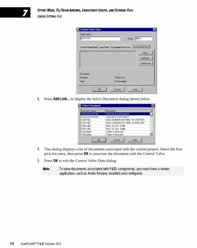
5H@5BD=?45� D?�6B?= 1BB?GC� 3?>C9CD5>3I 3853;C� 1>4 5HD5B>1< 69<5C
<9>;9>7 5HD5B>1< 69<5C
AutoPLANT® P&ID Version 16.07-6
�
#� Press Add Link… to display the Select Document dialog shown below.
$� This dialog displays a list of documents associated with the current project. Select the firstpick-list entry, then press OK to associate the document with the Control Valve.
%� Press OK to exit the Control Valve Data dialog.
>_dU To view documents associated with P&ID components, you must have a viewerapplication, such as Rebis Review, installed and configured.
����������������������� �������������
In this chapter, you will continue to explore the advanced features available in theExpert Mode of operation. You will also learn how to add a Process Safety Valve(PSV) to a Tower, add an Assembly to a Process Line, and create an ExchangeDrawing.
ADDING A PSV TO A TOWER 8-2
ATTACHING AN ASSEMBLY TO A PROCESS LINE 8-6
CREATING AN EXCHANGE DRAWING 8-7
CONCLUSION 8-8
� � � � � � � �
�
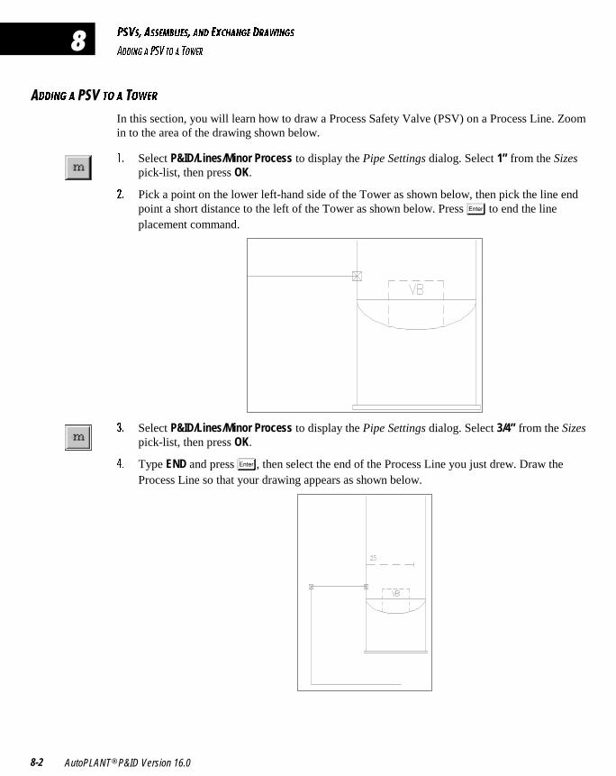
@CFC� 1CC5=2<95C� 1>4 5H381>75 4B1G9>7C
1449>7 1 @CF D? 1 D?G5B
AutoPLANT® P&ID Version 16.08-2
�
�449>7 1 ���D? 1 �?G5B
In this section, you will learn how to draw a Process Safety Valve (PSV) on a Process Line. Zoomin to the area of the drawing shown below.
!� Select P&ID/Lines/Minor Process to display the Pipe Settings dialog. Select 1” from the Sizespick-list, then press OK.
"� Pick a point on the lower left-hand side of the Tower as shown below, then pick the line endpoint a short distance to the left of the Tower as shown below. Press � to end the lineplacement command.
#� Select P&ID/Lines/Minor Process to display the Pipe Settings dialog. Select 3/4” from the Sizespick-list, then press OK.
$� Type END and press �, then select the end of the Process Line you just drew. Draw theProcess Line so that your drawing appears as shown below.
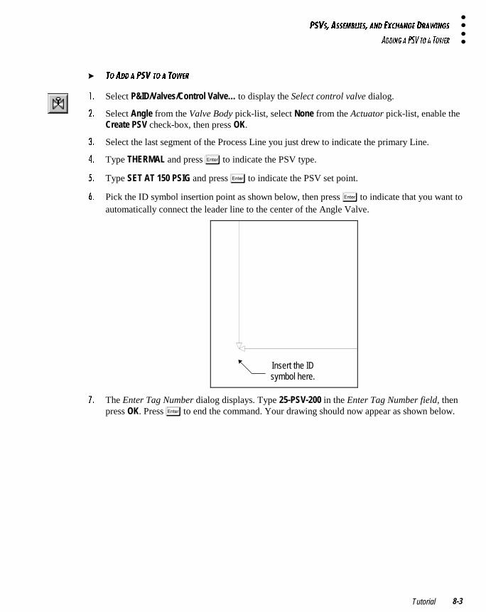
@CFC� 1CC5=2<95C� 1>4 5H381>75 4B1G9>7C
1449>7 1 @CF D? 1 D?G5B
Tutorial 8-3
� D? 144 1 @CF D? 1 D?G5B
!� Select P&ID/Valves/Control Valve… to display the Select control valve dialog.
"� Select Angle from the Valve Body pick-list, select None from the Actuator pick-list, enable theCreate PSV check-box, then press OK.
#� Select the last segment of the Process Line you just drew to indicate the primary Line.
$� Type THERMAL and press � to indicate the PSV type.
%� Type SET AT 150 PSIG and press � to indicate the PSV set point.
&� Pick the ID symbol insertion point as shown below, then press � to indicate that you want toautomatically connect the leader line to the center of the Angle Valve.
Insert the IDsymbol here.
'� The Enter Tag Number dialog displays. Type 25-PSV-200 in the Enter Tag Number field, thenpress OK. Press � to end the command. Your drawing should now appear as shown below.
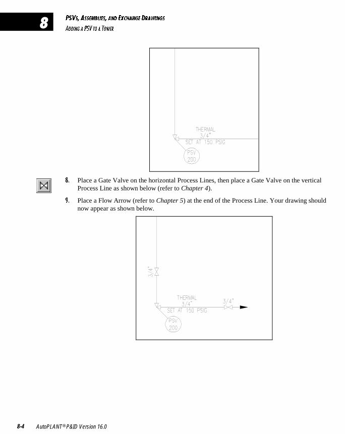
@CFC� 1CC5=2<95C� 1>4 5H381>75 4B1G9>7C
1449>7 1 @CF D? 1 D?G5B
AutoPLANT® P&ID Version 16.08-4
�
(� Place a Gate Valve on the horizontal Process Lines, then place a Gate Valve on the verticalProcess Line as shown below (refer to Chapter 4).
)� Place a Flow Arrow (refer to Chapter 5) at the end of the Process Line. Your drawing shouldnow appear as shown below.
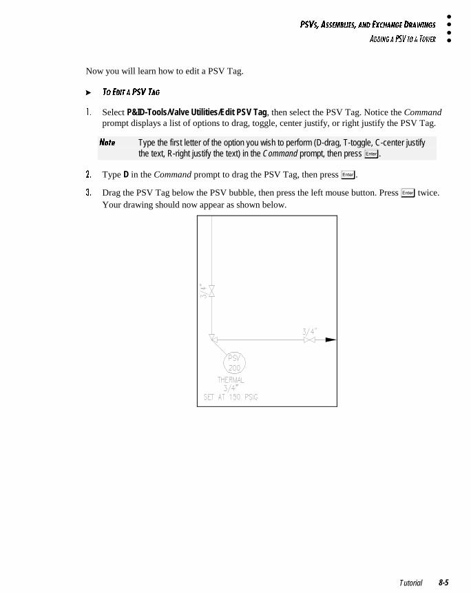
@CFC� 1CC5=2<95C� 1>4 5H381>75 4B1G9>7C
1449>7 1 @CF D? 1 D?G5B
Tutorial 8-5
Now you will learn how to edit a PSV Tag.
� D? 549D 1 @CF D17
!� Select P&ID-Tools/Valve Utilities/Edit PSV Tag, then select the PSV Tag. Notice the Commandprompt displays a list of options to drag, toggle, center justify, or right justify the PSV Tag.
>_dU Type the first letter of the option you wish to perform (D-drag, T-toggle, C-center justifythe text, R-right justify the text) in the Command prompt, then press �.
"� Type D in the Command prompt to drag the PSV Tag, then press �.
#� Drag the PSV Tag below the PSV bubble, then press the left mouse button. Press � twice.Your drawing should now appear as shown below.
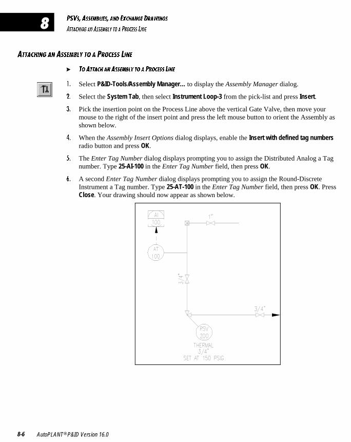
@CFC� 1CC5=2<95C� 1>4 5H381>75 4B1G9>7C
1DD1389>7 1> 1CC5=2<I D? 1 @B?35CC <9>5
AutoPLANT® P&ID Version 16.08-6
�
�DD1389>7 1> �CC5=2<I D? 1 �B?35CC �9>5
� D? 1DD138 1> 1CC5=2<I D? 1 @B?35CC <9>5
!� Select P&ID-Tools/Assembly Manager… to display the Assembly Manager dialog.
"� Select the System Tab, then select Instrument Loop-3 from the pick-list and press Insert.
#� Pick the insertion point on the Process Line above the vertical Gate Valve, then move yourmouse to the right of the insert point and press the left mouse button to orient the Assembly asshown below.
$� When the Assembly Insert Options dialog displays, enable the Insert with defined tag numbersradio button and press OK.
%� The Enter Tag Number dialog displays prompting you to assign the Distributed Analog a Tagnumber. Type 25-AI-100 in the Enter Tag Number field, then press OK.
&� A second Enter Tag Number dialog displays prompting you to assign the Round-DiscreteInstrument a Tag number. Type 25-AT-100 in the Enter Tag Number field, then press OK. PressClose. Your drawing should now appear as shown below.
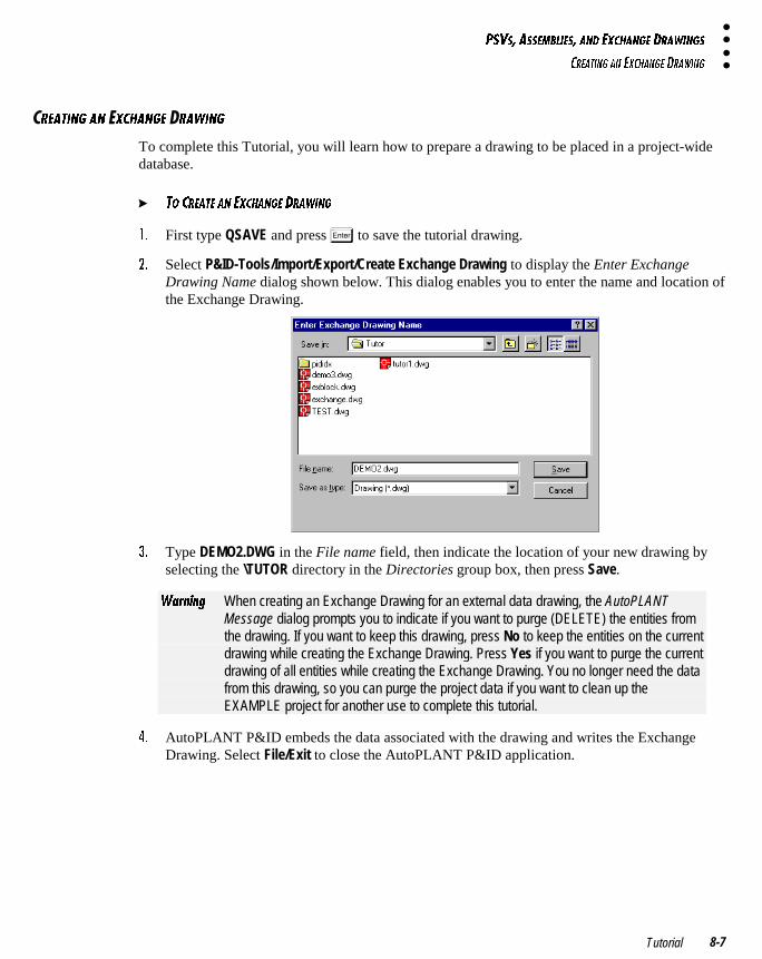
@CFC� 1CC5=2<95C� 1>4 5H381>75 4B1G9>7C
3B51D9>7 1> 5H381>75 4B1G9>7
Tutorial 8-7
B51D9>7 1> �H381>75 �B1G9>7
To complete this Tutorial, you will learn how to prepare a drawing to be placed in a project-widedatabase.
� D? 3B51D5 1> 5H381>75 4B1G9>7
!� First type QSAVE and press � to save the tutorial drawing.
"� Select P&ID-Tools/Import/Export/Create Exchange Drawing to display the Enter ExchangeDrawing Name dialog shown below. This dialog enables you to enter the name and location ofthe Exchange Drawing.
#� Type DEMO2.DWG in the File name field, then indicate the location of your new drawing byselecting the \TUTOR directory in the Directories group box, then press Save.
GQb^Y^W When creating an Exchange Drawing for an external data drawing, the AutoPLANTMessage dialog prompts you to indicate if you want to purge (DELETE) the entities fromthe drawing. If you want to keep this drawing, press No to keep the entities on the currentdrawing while creating the Exchange Drawing. Press Yes if you want to purge the currentdrawing of all entities while creating the Exchange Drawing. You no longer need the datafrom this drawing, so you can purge the project data if you want to clean up theEXAMPLE project for another use to complete this tutorial.
$� AutoPLANT P&ID embeds the data associated with the drawing and writes the ExchangeDrawing. Select File/Exit to close the AutoPLANT P&ID application.

@CFC� 1CC5=2<95C� 1>4 5H381>75 4B1G9>7C
3?>3<EC9?>
AutoPLANT® P&ID Version 16.08-8
�
?>3<EC9?>
You have now completed the P&ID Tutorial, but in no way has the learning process ended. Youshould take the time to review specific examples in this Tutorial, and experiment with them as theyapply to your drawing environment. Refer to the P&ID on-line Help for a more detailedexplanation of available features and functions. Customization issues are also covered extensivelyin the Help.

����������������� �����
This section introduces the AutoPLANT Document Manager application that isshipped free of charge with your AutoPLANT software. This utility is used fororganizing, revising, and previewing documents on a project-by-project basis.Document Manager also provides its own on-line help file which covers the availablefeatures and functions.
CHAPTER 9: DOCUMENT MANAGER
� � � � �
���
�������������
This chapter introduces you to the AutoPLANT Document Manager application,which enables you to organize, revise, and preview project documents created withregistered Rebis applications. This section explains how to start Document Managerand provides an introduction to the user interface, including toolbars. During thissession, you will learn how to modify the project document tree, add documents to aproject, and add revision marks to a document.
WHAT IS DOCUMENT MANAGER? 9-2
INSTALLATION 9-2
FEATURES 9-2
STARTING DOCUMENT MANAGER AND OPENING A PROJECT 9-5
A TOUR OF THE INTERFACE 9-7
DOCUMENT MANAGER ON-LINE HELP 9-9
VIEWING A PROJECT CONFIGURATION 9-10
REGISTERING AN APPLICATION IN DOCUMENT MANAGER 9-11
ADDING A DOCUMENT TO A PROJECT TREE 9-13
ADDING REVISION MARKS TO A DOCUMENT 9-14
� � � � � � � �
�
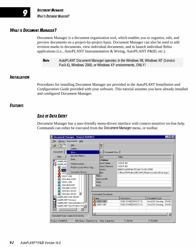
4?3E=5>D=1>175B
G81D 9C 4?3E=5>D=1>175B/
AutoPLANT® P&ID Version 16.09-2
�
81D 9C �?3E=5>D�1>175B�
Document Manager is a document organization tool, which enables you to organize, edit, andpreview documents on a project-by-project basis. Document Manager can also be used to addrevision marks to documents, view individual documents, and to launch individual Rebisapplications (i.e., AutoPLANT Instrumentation & Wiring, AutoPLANT P&ID, etc.).
>_dU AutoPLANT Document Manager operates in the Windows 98, Windows NT (ServicePack 6), Windows 2000, or Windows XP environments, ONLY!
�>CD1<<1D9?>
Procedures for installing Document Manager are provided in the AutoPLANT Installation andConfiguration Guide provided with your software. This tutorial assumes you have already installedand configured Document Manager.
�51DEB5C
�1C5 ?6 1D1 �>DBI
Document Manager has a user-friendly menu-driven interface with context-sensitive on-line help.Commands can either be executed from the Document Manager menu, or toolbar.
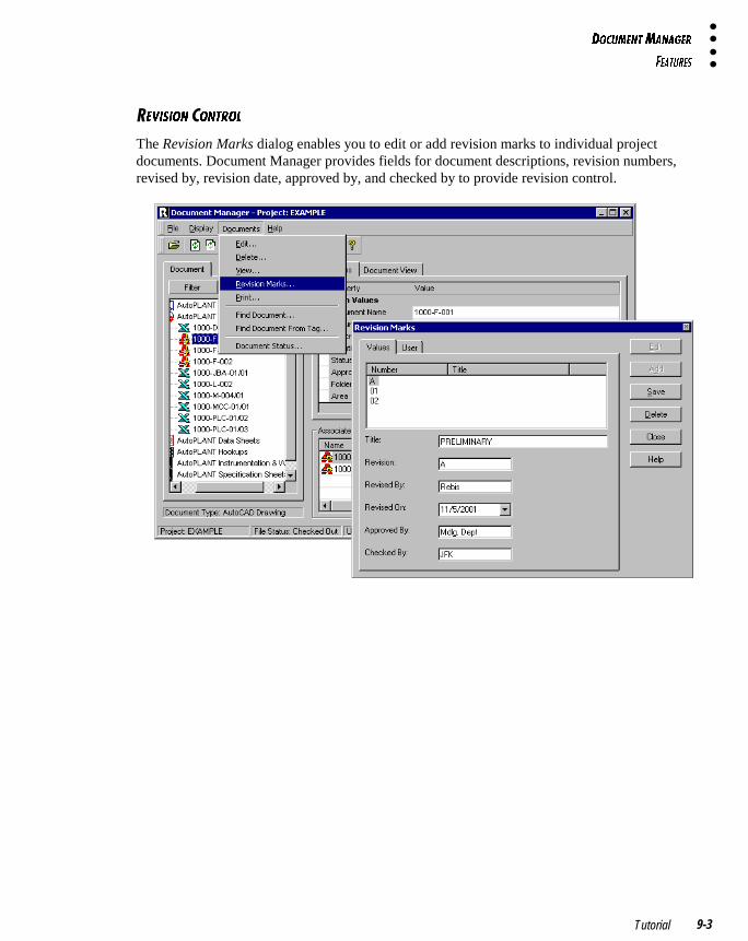
4?3E=5>D=1>175B
651DEB5C
Tutorial 9-3
5F9C9?> �?>DB?<
The Revision Marks dialog enables you to edit or add revision marks to individual projectdocuments. Document Manager provides fields for document descriptions, revision numbers,revised by, revision date, approved by, and checked by to provide revision control.
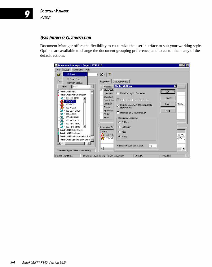
4?3E=5>D=1>175B
651DEB5C
AutoPLANT® P&ID Version 16.09-4
�
�C5B �>D5B6135 �ECD?=9J1D9?>
Document Manager offers the flexibility to customize the user interface to suit your working style.Options are available to change the document grouping preference, and to customize many of thedefault actions.
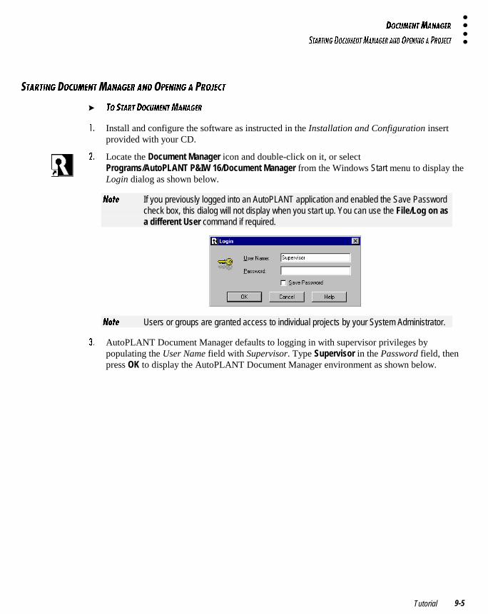
4?3E=5>D=1>175B
CD1BD9>7 4?3E=5>D=1>175B 1>4 ?@5>9>7 1 @B?:53D
Tutorial 9-5
�D1BD9>7 �?3E=5>D�1>175B 1>4 �@5>9>7 1 �B?:53D
� D? CD1BD 4?3E=5>D=1>175B
!� Install and configure the software as instructed in the Installation and Configuration insertprovided with your CD.
"� Locate the Document Manager icon and double-click on it, or selectPrograms/AutoPLANT P&IW 16/Document Manager from the Windows Start menu to display theLogin dialog as shown below.
>_dU If you previously logged into an AutoPLANT application and enabled the Save Passwordcheck box, this dialog will not display when you start up. You can use the File/Log on asa different User command if required.
>_dU Users or groups are granted access to individual projects by your System Administrator.
#� AutoPLANT Document Manager defaults to logging in with supervisor privileges bypopulating the User Name field with Supervisor. Type Supervisor in the Password field, thenpress OK to display the AutoPLANT Document Manager environment as shown below.
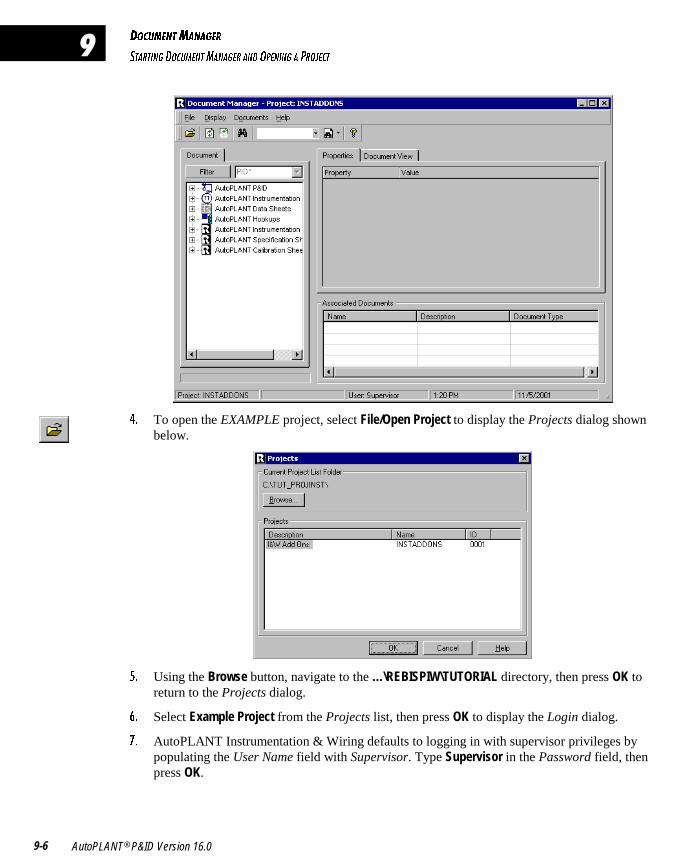
4?3E=5>D=1>175B
CD1BD9>7 4?3E=5>D=1>175B 1>4 ?@5>9>7 1 @B?:53D
AutoPLANT® P&ID Version 16.09-6
�
$� To open the EXAMPLE project, select File/Open Project to display the Projects dialog shownbelow.
%� Using the Browse button, navigate to the …\REBISPIW\TUTORIAL directory, then press OK toreturn to the Projects dialog.
&� Select Example Project from the Projects list, then press OK to display the Login dialog.
'� AutoPLANT Instrumentation & Wiring defaults to logging in with supervisor privileges bypopulating the User Name field with Supervisor. Type Supervisor in the Password field, thenpress OK.
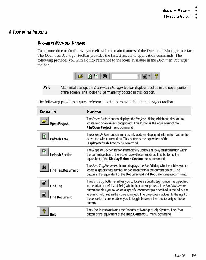
4?3E=5>D=1>175B
1 D?EB ?6 D85 9>D5B6135
Tutorial 9-7
�?EB ?6 D85 �>D5B6135
?3E=5>D 1>175B �??<21B
Take some time to familiarize yourself with the main features of the Document Manager interface.The Document Manager toolbar provides the fastest access to application commands. Thefollowing provides you with a quick reference to the icons available in the Document Managertoolbar.
>_dU After initial startup, the Document Manager toolbar displays docked in the upper portionof the screen. This toolbar is permanently docked in this location.
The following provides a quick reference to the icons available in the Project toolbar.
D??<21B 93?> 45C3B9@D9?>
Open ProjectThe Open Project button displays the Projects dialog which enables you tolocate and open an existing project. This button is the equivalent of theFile/Open Project menu command.
Refresh TreeThe Refresh Tree button immediately updates displayed information within theactive tab with current data. This button is the equivalent of theDisplay/Refresh Tree menu command.
Refresh SectionThe Refresh Section button immediately updates displayed information withinthe current section of the active tab with current data. This button is theequivalent of the Display/Refresh Section menu command.
Find Tag/DocumentThe Find Tag/Document button displays the Find dialog which enables you tolocate a specific tag number or document within the current project. Thisbutton is the equivalent of the Documents/Find Document menu command.
Find Tag
Find Document
The Find Tag button enables you to locate a specific tag number (as specifiedin the adjacent left-hand field) within the current project. The Find Documentbutton enables you to locate a specific document (as specified in the adjacentleft-hand field) within the current project. The drop-down pick-list to the right ofthese toolbar icons enables you to toggle between the functionality of thesebuttons.
HelpThe Help button activates the Document Manager Help System. The Helpbutton is the equivalent of the Help/Contents… menu command.
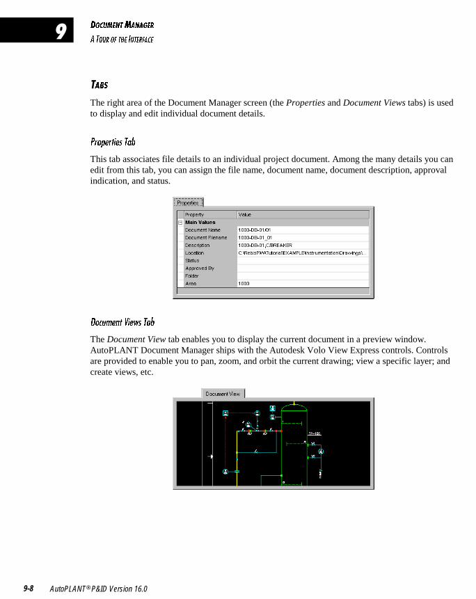
4?3E=5>D=1>175B
1 D?EB ?6 D85 9>D5B6135
AutoPLANT® P&ID Version 16.09-8
�
�12C
The right area of the Document Manager screen (the Properties and Document Views tabs) is usedto display and edit individual document details.
@b_`UbdYUc DQR
This tab associates file details to an individual project document. Among the many details you canedit from this tab, you can assign the file name, document name, document description, approvalindication, and status.
4_Se]U^d FYUgc DQR
The Document View tab enables you to display the current document in a preview window.AutoPLANT Document Manager ships with the Autodesk Volo View Express controls. Controlsare provided to enable you to pan, zoom, and orbit the current drawing; view a specific layer; andcreate views, etc.
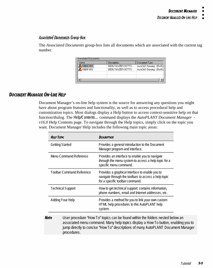
4?3E=5>D=1>175B
4?3E=5>D=1>175B ?>�<9>5 85<@
Tutorial 9-9
1cc_SYQdUT 4_Se]U^dc 7b_e`�2_h
The Associated Documents group-box lists all documents which are associated with the current tagnumber.
�?3E=5>D�1>175B �>��9>5 �5<@
Document Manager’s on-line help system is the source for answering any questions you mighthave about program features and functionality, as well as to access procedural help andcustomization topics. Most dialogs display a Help button to access context-sensitive help on thatfunction/dialog. The Help/Contents… command displays the AutoPLANT Document Manager -v16.0 Help Contents page. To navigate through the Help topics, simply click on the topic youwant. Document Manager Help includes the following main topic areas:
85<@ D?@93 45C3B9@D9?>
Getting Started Provides a general introduction to the DocumentManager program and interface.
Menu Command Reference Provides an interface to enable you to navigatethrough the menu system to access a help topic for aspecific menu command.
Toolbar Command Reference Provides a graphical interface to enable you tonavigate through the toolbars to access a help topicfor a specific toolbar command.
Technical Support How to get technical support: contains information,phone numbers, email and Internet addresses, etc.
Adding Your Help Provides a method for you to link your own customHTML help procedures to this AutoPLANT helpsystem.
>_dU User procedure “How To” topics can be found within the folders nested below anassociated menu command. Many help topics display a How To button, enabling you tojump directly to concise “How To” descriptions of many AutoPLANT Document Managerprocedures.
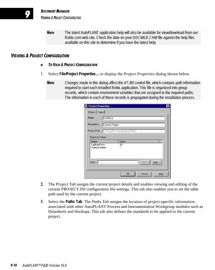
4?3E=5>D=1>175B
F95G9>7 1 @B?:53D 3?>697EB1D9?>
AutoPLANT® P&ID Version 16.09-10
�
>_dU The latest AutoPLANT application help will also be available for view/download from ourRebis.com web site. Check the date on your DOCMGR.CHM file against the help filesavailable on this site to determine if you have the latest help.
�95G9>7 �B?:53D �?>697EB1D9?>
� D? F95G 1 @B?:53D 3?>697EB1D9?>
!� Select File/Project Properties… to display the Project Properties dialog shown below.
>_dU Changes made in this dialog affect the AT.INI control file, which contains path informationrequired to start each installed Rebis application. This file is organized into grouprecords, which contain environment variables that are assigned to the required paths.The information in each of these records is propagated during the installation process.
"� The Project Tab assigns the current project details and enables viewing and editing of thecurrent PROJECT.INI configuration file settings. This tab also enables you to set the tablepath used by the current project.
#� Select the Paths Tab. The Paths Tab assigns the location of project-specific informationassociated with other AutoPLANT Process and Instrumentation Workgroup modules such asDatasheets and Hookups. This tab also defines the standards to be applied to the currentproject.
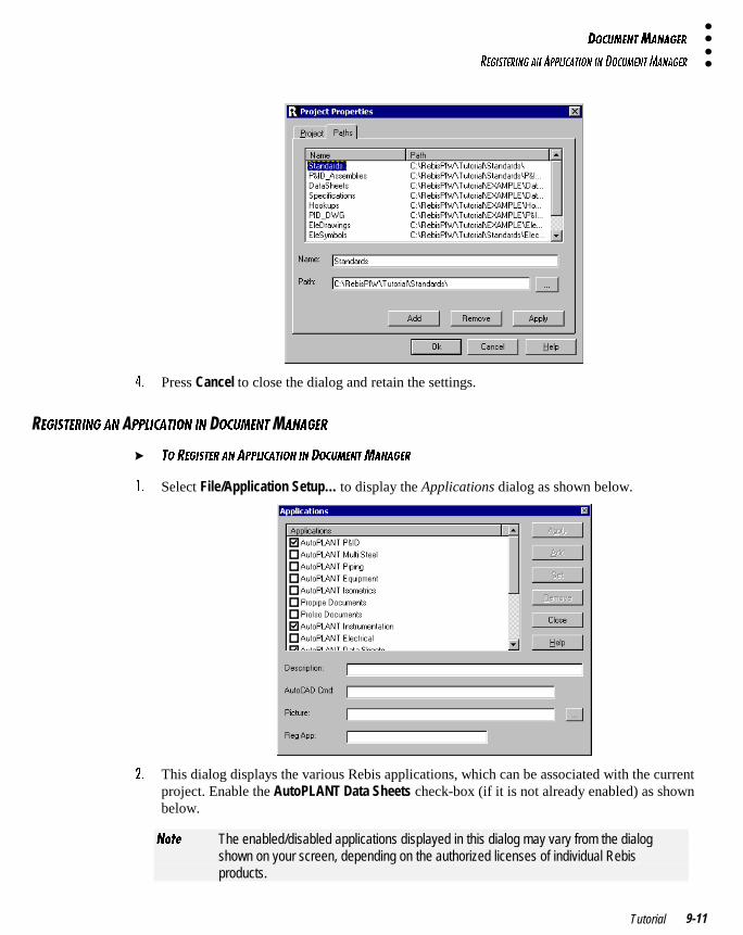
4?3E=5>D=1>175B
B579CD5B9>7 1> 1@@<931D9?> 9> 4?3E=5>D=1>175B
Tutorial 9-11
$� Press Cancel to close the dialog and retain the settings.
�579CD5B9>7 1> @@<931D9?> 9> �?3E=5>D�1>175B
� D? B579CD5B 1> 1@@<931D9?> 9> 4?3E=5>D=1>175B
!� Select File/Application Setup… to display the Applications dialog as shown below.
"� This dialog displays the various Rebis applications, which can be associated with the currentproject. Enable the AutoPLANT Data Sheets check-box (if it is not already enabled) as shownbelow.
>_dU The enabled/disabled applications displayed in this dialog may vary from the dialogshown on your screen, depending on the authorized licenses of individual Rebisproducts.
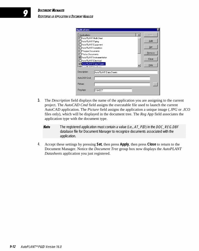
4?3E=5>D=1>175B
B579CD5B9>7 1> 1@@<931D9?> 9> 4?3E=5>D=1>175B
AutoPLANT® P&ID Version 16.09-12
�
#� The Description field displays the name of the application you are assigning to the currentproject. The AutoCAD Cmd field assigns the executable file used to launch the currentAutoCAD application. The Picture field assigns the application a unique image (.JPG or .ICOfiles only), which will be displayed in the document tree. The Reg App field associates theapplication type with the document type.
>_dU The registered application must contain a value (i.e., AT_PID) in the DOC_REG.DBFdatabase file for Document Manager to recognize documents associated with theapplication.
$� Accept these settings by pressing Set, then press Apply, then press Close to return to theDocument Manager. Notice the Document Tree group box now displays the AutoPLANTDatasheets application you just registered.
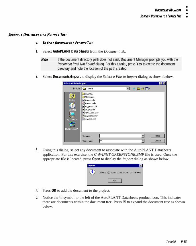
4?3E=5>D=1>175B
1449>7 1 4?3E=5>D D? 1 @B?:53D DB55
Tutorial 9-13
449>7 1 �?3E=5>D D? 1 �B?:53D �B55
� D? 144 1 4?3E=5>D D? 1 @B?4E3D DB55
!� Select AutoPLANT Data Sheets from the Document tab.
>_dU If the document directory path does not exist, Document Manager prompts you with theDocument Path Not Found dialog. For this tutorial, press Yes to create the documentdirectory and note the location of the path created.
"� Select Documents/Import to display the Select a File to Import dialog as shown below.
#� Using this dialog, select any document to associate with the AutoPLANT Datasheetsapplication. For this exercise, the C:\WINNT\GREENSTONE.BMP file is used. Once theappropriate file is located, press Open to display the Import dialog as shown below.
$� Press OK to add the document to the project.
%� Notice the symbol to the left of the AutoPLANT Datasheets product icon. This indicatesthere are documents within the document tree. Press to expand the document tree as shownbelow.
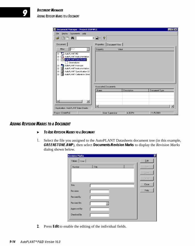
4?3E=5>D=1>175B
1449>7 B5F9C9?>=1B;C D? 1 4?3E=5>D
AutoPLANT® P&ID Version 16.09-14
�
449>7 �5F9C9?>�1B;C D? 1 �?3E=5>D
� D? 144 B5F9C9?>=1B;C D? 1 4?3E=5>D
!� Select the file you assigned to the AutoPLANT Datasheets document tree (in this example,GREENSTONE.BMP), then select Documents/Revision Marks to display the Revision Marksdialog shown below.
"� Press Edit to enable the editing of the individual fields.
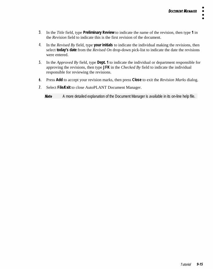
4?3E=5>D=1>175B
Tutorial 9-15
#� In the Title field, type Preliminary Review to indicate the name of the revision, then type 1 inthe Revision field to indicate this is the first revision of the document.
$� In the Revised By field, type your initials to indicate the individual making the revisions, thenselect today’s date from the Revised On drop-down pick-list to indicate the date the revisionswere entered.
%� In the Approved By field, type Dept. 1 to indicate the individual or department responsible forapproving the revisions, then type JFK in the Checked By field to indicate the individualresponsible for reviewing the revisions.
&� Press Add to accept your revision marks, then press Close to exit the Revision Marks dialog.
'� Select File/Exit to close AutoPLANT Document Manager.
>_dU A more detailed explanation of the Document Manager is available in its on-line help file.