atomistic simulations of plasma-material interactions in
TRANSCRIPT

UNIVERSITY OF HELSINKI REPORT SERIES IN PHYSICS
HU-P-D257
Atomistic simulations of plasma-materialinteractions in fusion reactors
Elnaz Safi
Division of Materials Physics
Department of Physics
Faculty of Science
University of HelsinkiHelsinki, Finland
ACADEMIC DISSERTATION
To be presented, with the permission of the Faculty of Science of the University of Helsinki, forpublic criticism in auditorium XIII of the Main Building of the University of Helsinki, on
March 3rd 2018, at 12 o’clock noon.
HELSINKI 2018

ISBN 978-951-51-4105-7 (printed version)ISSN 0356-0961
Helsinki 2018Unigrafia Print
ISBN 978-951-51-4106-4 (PDF version)http://ethesis.helsinki.fi
Helsinki 2018Electronic Publications @ University of Helsinki
I
Elnaz Safi, Atomistic simulations of plasma-material interactions in fusion reactors, Uni-versity of Helsinki, 2018, 52 p. + appendices, University of Helsinki Report Series in Physics,HU-P-D257, ISSN 0356-0961, ISBN 978-951-51-4105-7 (printed version), ISBN 978-951-51-4106-4 (PDF version)
Abstract
With increasing demand for the energy in last decades, replacing scarce fossil fuels with newenergy resources is inevitable. Currently, there is no clear alternative to the old and regularenergy production methods for a clean future. However, nuclear fusion power may offer prac-tical, power-plant-scale energy production with an unlimited fuel supply.
A major challenge to overcome in the fusion reaction is to produce more energy than it con-sumes under extremely harsh operating conditions. In the last few decades, a wide range ofstudies have been carried out to investigate fusion performance and fusion reactor designs.
ITER will be the first experimental tokamak-like nuclear fusion reactor to produce net energy,based on deuterium–tritium plasma. Due to the ITER design and operation requirements, ex-treme conditions are expected for plasma-facing components, such as very large thermal loads,temperature and particle fluxes. Therefore, selecting appropriate materials for different com-ponents of the device is critical and highly demanding.
The main candidates for the first wall materials in future fusion reactor, ITER are tungsten forthe divertor plates and beryllium for the main wall. Moreover, special low-activation ferriticsteels are developed for being used as structural materials in blanket modules. In addition, var-ious steels containing of iron and carbon are being considered for the main wall of the DEMO.
The plasma cannot be confined infinitely and to control the contact between the escaped plasmaand the wall, the area of interaction is restricted to divertor or limiter structures, leading to ero-sion of them. This phenomenon can become a show stopper by limiting the lifetime of wallmaterials. Therefore, characterizing the erosion behaviour and morphology changes of thesecomponents and understanding the underlying mechanism are essential toward predicting andultimately controlling the adverse effects of plasma surface interactions.
Experiments in the different tokamaks and linear plasma devices, as well as those using ionbeams are dedicated to study plasma surface interactions. However, experiments show a com-plex outcome and provide insufficient information to understand the underlying mechanism ifthe physics is poorly understood. In addition to experiments, computer simulations to studyplasma surface interaction have also contributed to a better understanding of future fusion re-actors and characterization of this mechanism in a wide range of time and length scales.
In this dissertation, the plasma wall interactions such as erosion and ion reflection for the first-wall materials of future fusion reactors have been studied by different computational methods.The interactions of different materials with plasma and impurity particles were modelled. Thework was mainly based on molecular dynamics (MD) simulations and an Object Kinetic Monte
II
Carlo (OKMC) algorithm to extend earlier results to a longer time and length scales and therebyenables direct comparison with performed experiments.
First, deuterium irradiation on pure Fe, Fe with 1% C impurity and Fe3C, under different irra-diation energies and substrate temperatures was modelled. C preferential sputtering to Fe wasreported, while D was found to be mainly trapped as D2 in bubbles. Furthermore, a MD studyto investigate the effect of plasma impurities D, Ar and Ne on the erosion and surface structureof W and Be was carried out for different fractions of Ar and Ne. In W, only noble gas impu-rities were responsible for surface erosion in the energy range studied here, and the sputteringmechanism was physical. For Be at impact energies higher than 100eV, the total Be sputteringyield in the presence of Ar and Ne impurities was found to be three times higher than for puredeuterium irradiation. The effect of surface temperature on the results was negligible.
Furthermore, the effect of reactor-relevant parameters on Be erosion behaviour and surfacechanges have been investigated using MD and subsequently a multi-scale approach (KMC-MD). This study gave us a better understanding of the erosion mechanism and improved theknowledge of molecular erosion and its underlying structure. Moreover, this approach was ableto offer a more precise database of erosion yields to the large-scale-impurity-transport codessuch as ERO. The findings correlate well with different experiments performed at the JET andPISCES-B devices.

Contents
Abstract I
Contents III
1 Introduction 1
2 Purpose and Structure 4
2.1 Summaries of the original publications . . . . . . . . . . . . . . . . . . . . . . 4
2.2 Author’s contribution . . . . . . . . . . . . . . . . . . . . . . . . . . . . . . . 6
2.3 Other publications with the author’s contribution . . . . . . . . . . . . . . . . 6
3 Plasma-material interactions 8
3.1 Thermonuclear fusion . . . . . . . . . . . . . . . . . . . . . . . . . . . . . . . 8
3.2 Tokamak-like fusion reactors . . . . . . . . . . . . . . . . . . . . . . . . . . . 9
3.3 Nature of plasma-wall interaction . . . . . . . . . . . . . . . . . . . . . . . . 10
3.4 Ion irradiation of materials . . . . . . . . . . . . . . . . . . . . . . . . . . . . 12
3.4.1 Nuclear stopping . . . . . . . . . . . . . . . . . . . . . . . . . . . . . 12
3.4.2 Electronic stopping . . . . . . . . . . . . . . . . . . . . . . . . . . . . 13
3.4.3 Implantation . . . . . . . . . . . . . . . . . . . . . . . . . . . . . . . 14
3.4.4 Reflection . . . . . . . . . . . . . . . . . . . . . . . . . . . . . . . . . 14
3.4.5 Erosion . . . . . . . . . . . . . . . . . . . . . . . . . . . . . . . . . . 15
4 Methods 17
4.1 Classical Molecular Dynamics . . . . . . . . . . . . . . . . . . . . . . . . . . 17
4.1.1 The MD algorithm . . . . . . . . . . . . . . . . . . . . . . . . . . . . 17
4.1.2 Interatomic Potentials . . . . . . . . . . . . . . . . . . . . . . . . . . 20
III

IV
4.2 Binary Collision Approximation . . . . . . . . . . . . . . . . . . . . . . . . . 23
4.3 Kinetic Monte Carlo . . . . . . . . . . . . . . . . . . . . . . . . . . . . . . . 24
4.3.1 Basic approach . . . . . . . . . . . . . . . . . . . . . . . . . . . . . . 25
4.3.2 Object Kinetic Monte Carlo . . . . . . . . . . . . . . . . . . . . . . . 26
5 Sputtering of Iron-based alloys for DEMO applications 28
6 Co-bombardment of W and Be 32
6.1 Impurity effects on sputtering . . . . . . . . . . . . . . . . . . . . . . . . . . . 32
6.2 Materials modification . . . . . . . . . . . . . . . . . . . . . . . . . . . . . . 33
7 Multi-scale modeling of Be erosion 36
8 Summary 43
Acknowledgments 45
Bibliography 46
Chapter 1
Introduction
One of the most important challenges of the 21st century is to develop new energy resourcesthat can fulfil the increasing demand for energy caused by the current population growth. Theprimary energy sources and fossil fuels such as coal, heavy crude oil and natural gas are becom-ing scarce [1] and their extraction becoming questionable from the economics point of view,therefore, new energy resources must replace them. In addition, these primary energy sourcesemit the green-house gas (CO2), which could affect the atmosphere and increase the globalwarming and climate change [2]. During the last decades, a few reliable and clean solutions asalternatives to fossil fuels have been under development; these include wind, solar and hydro-power energies. On the one hand, these renewable energy sources are greatly progressing fora safe and CO2-free future, and on the other hand, their efficiency highly depends on the geo-graphical location and climate conditions [3].
Nuclear fusion may offer a power plant scale energy production with an almost unlimited fuelsupply. It is safe, has no emission of harmful gases, no long lived radioactive waste and it isindependent from local weather and geographical conditions. Fusion is a process where largeamount of energy is produced by the same process that happens in stars. In fusion, light atomsfuse into new heavier elements that release the excess binding energy as heat. The most suit-able fusion reaction for an earthbound fusion is between two hydrogen (H) isotopes, deuterium(D) and tritium (T). When these two D and T nuclei fuse together (Fig. 1.1), on one hand,they form a neutron (n) with an energy of 14.1 MeV. Later, this hot neutron is captured, andits energy can be used just as in a conventional power plant; e.g. to heat a coolant fluid (e.g.water) for producing steam to run a turbine. On the other hand, a helium nucleus (He) with anenergy of 3.5 MeV is produced. Since the helium nuclei are charged, they will stay inside thefusion reactor and transfer their energy to the plasma, keeping it hot. Another benefit of fusionis the abundancy of its fuel components in the earth: about 33 g of D is available in every cubicmetre of sea water and T can be generated from lithium (Li), which is a common element inthe earth’s crust. Further, the fusion reaction is very efficient and a very large amount of energyis produced only by consuming a small amount of fuel; 250 kg of fuel could run a D-T fusionpower plant for a year [4].
1

2
Figure 1.1: D-T fusion [5]. the fusion of deuterium with tritium creates helium4, frees a remaining neutron,
and releases energy. Because E = ∆MC2, when two atoms are fused, a very small amount of mass can be
converted into a large amount of energy.
In thermonuclear fusion, the nuclei must be forced together in spite of repulsive electrostaticCoulomb force, by heating the fuel up to temperatures around 200 million degrees, for the D+Treaction. At these temperatures atoms are highly ionized and form a plasma. The primaryrequirements for fusion reaction are very precise and the process could easily stop if these re-quirements are not met during the process. This is the main reason why there is no fusionreactor up to this date which can produce more energy than it consumes. So far, the highestenergy gain factor (Q) was reached at the Joint European Torus (JET), the largest fusion reactorin the world, with Q = 0.64 in 1997 [6]. The power output is maximized by controlling essen-tial plasma parameters, such as the confinement time, the density and the temperature, whichcause major challenges. For this purpose different fusion devices have been developed, whilethe most favourable and promising one is the tokamak.
In a tokamak reactor, the plasma is confined by combining poloidal and toroidal magneticfield and isolated by a twisted-torus shaped vacuum vessel [7]. Due to finite plasma confine-ment, particles can escape from the core and either hit the surrounding wall or join to otherimpurities and He nuclei in the exhaust region, called divertor. The plasma will interact withthe inner surrounding walls of the reactor, the plasma facing components (PFCs). The PFCsinclude the main wall and the divertor. These plasma wall interactions (PWIs) can harm boththe wall and the plasma. The wall gets thinner due to erosion. If the eroded particles migrate tothe confined plasma, they will cause energy loss by radiation. Radiation losses depend on theatomic number of the impurity (Z) where heavier elements are more harmful [8]. Moreover,controlling the erosion is important to maximize the lifetime of wall materials.
The choice of materials exposed to plasma particles is critical to provide safe operation ofthe reactor and to be economically reasonable [9]. Examples of suitable plasma facing materi-als (PFMs) are tungsten (W) for the divertor region and beryllium (Be) for the first wall. W isselected because of its high sputtering threshold and low fuel retention [10]. Moreover, W hasgood power-handling capabilities due to its high melting point, however, it is a heavy (high-Z)material and so its erosion must be controlled. Be is a low-Z material which has been chosendue to its low plasma contamination, fuel retention and its oxygen gettering properties [11].Nevertheless, Be is only suitable to use in areas with lowest heat loads and weakest plasma-

3
surface interactions (PSIs) due to its low sputtering energy threshold. Moreover, the materialdamage will be beyond the tokamak first wall and divertor, since the energetic particles canpenetrate into the tokamak’s blanket area which is mainly made of high-strength copper andstainless steel. Special low-activation ferritic steels are developed for being used as structuralmaterials in blanket modules.
The behaviour of these materials in a reactor can be studied with experimental fusion devices.The road-map towards a future fusion power plant is built based in various devices. Due totheir main wall material choice, the most relevant devices for the present work are: JET, itssuccessor ITER (see Fig 1.2) and a demonstration reactor called DEMO. JET represents a purescientific experiment aiming to test different materials and plasma configurations for ITER. Thereactor scale experiment ITER is designed to deliver ten times the power it consumes, demon-strating that heat ignition can be achieved. The next foreseen device, DEMO, is expected to bethe first fusion power plant to prove that production of net electricity in the grid is possible [12].
However, plasma parameters and desired conditions for a full-scale power plant cannot bereproduced in current experimental facilities and a complete experimental device is difficultto reach. Computer simulations techniques, such as those used in this thesis are required toprovide a better insight on the experimental results, to achieve a theoretical conception of theexperimental systems, and to predict the following steps more accurately. Further, it provides abetter understanding of the behaviour of materials in a future fusion reactor and facilitates thedevelopment of a specific material.
The present thesis focuses on PWIs happening and expected in the fusion reactor main walland vacuum vessel. These results will provide more accurate data for further plasma-wall in-teraction studies, and will help in the interpretation of experiments.
Figure 1.2: Next-generation fusion reactor ITER tokamak with plasma volume of 840 cubic meters and
energy gain factor of 10 which produces 500 MW energy for a pulse of 100 seconds. [7].

Chapter 2
Purpose and Structure
The purpose of this thesis is to study the surface phenomena of main wall materials in a fusionreactor when subjected to energetic plasma particles. The developed models and the outcomewill help better understanding of the experiments and also will provide a more precise and es-sential database for larger scale plasma-wall interaction models.
This thesis consists of a brief summary and four original articles, already published or ac-cepted for publication in international peer-review journals. The publications are given in theappendix and referred to with bold Roman numbers in the text.
The structure of this thesis is as follows. In the present section, the articles are summarizedand the author’s contribution to each of them is explained. In section 3, the basic concepts offusion reactor and plasma-surface interactions are described. All methods and models used inthis thesis are described in section 4. Sections 5, 6 and 7 summarize the main outcomes of thethesis. In section 8 the work is summarized and the acknowledgement and references are foundafterwards. At the end, the publications this thesis is based on are attached.
2.1 Summaries of the original publications
Publication I: Atomistic simulations of deuterium irradiation on iron-based alloys in fu-ture fusion reactorsE. Safi, J. Polvi, A. Lasa and K. Nordlund, Nuclear Materials and Energy 9, 571-575 (2016)
In this study, surface erosion and morphology changes of Iron-based alloys were in-vestigated under D ion irradiation by molecular dynamics (MD) simulations. Thisstudy helped in predicting the life-time and viability of reactors with steel walls.In the presence of carbon (C), C sputtering was preferential to iron (Fe) and thesurface was enriched with Fe. In general, our results revealed that if steels areused as a plasma-facing material, the presence of C in them will result in chemicalsputtering of carbon-containing molecules.
4
5
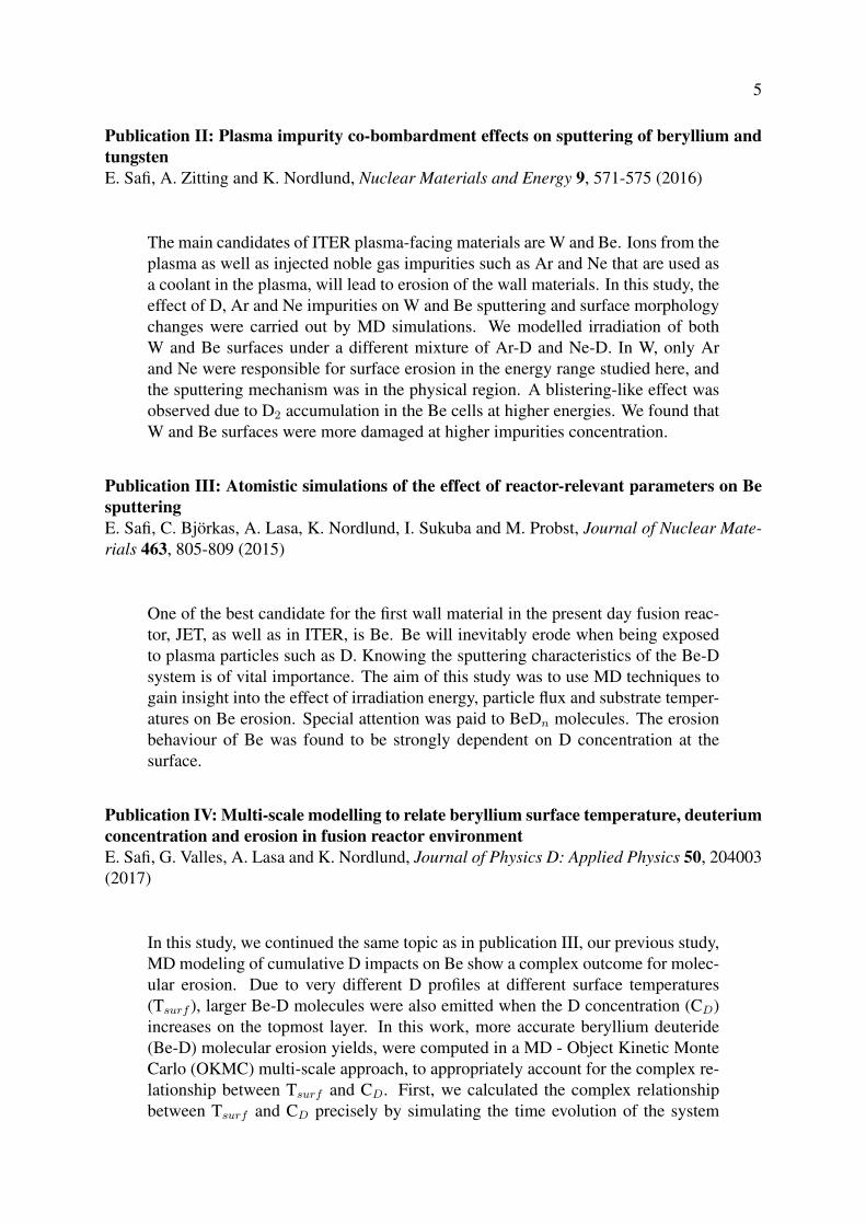
Publication II: Plasma impurity co-bombardment effects on sputtering of beryllium andtungstenE. Safi, A. Zitting and K. Nordlund, Nuclear Materials and Energy 9, 571-575 (2016)
The main candidates of ITER plasma-facing materials are W and Be. Ions from theplasma as well as injected noble gas impurities such as Ar and Ne that are used asa coolant in the plasma, will lead to erosion of the wall materials. In this study, theeffect of D, Ar and Ne impurities on W and Be sputtering and surface morphologychanges were carried out by MD simulations. We modelled irradiation of bothW and Be surfaces under a different mixture of Ar-D and Ne-D. In W, only Arand Ne were responsible for surface erosion in the energy range studied here, andthe sputtering mechanism was in the physical region. A blistering-like effect wasobserved due to D2 accumulation in the Be cells at higher energies. We found thatW and Be surfaces were more damaged at higher impurities concentration.
Publication III: Atomistic simulations of the effect of reactor-relevant parameters on BesputteringE. Safi, C. Björkas, A. Lasa, K. Nordlund, I. Sukuba and M. Probst, Journal of Nuclear Mate-rials 463, 805-809 (2015)
One of the best candidate for the first wall material in the present day fusion reac-tor, JET, as well as in ITER, is Be. Be will inevitably erode when being exposedto plasma particles such as D. Knowing the sputtering characteristics of the Be-Dsystem is of vital importance. The aim of this study was to use MD techniques togain insight into the effect of irradiation energy, particle flux and substrate temper-atures on Be erosion. Special attention was paid to BeDn molecules. The erosionbehaviour of Be was found to be strongly dependent on D concentration at thesurface.
Publication IV: Multi-scale modelling to relate beryllium surface temperature, deuteriumconcentration and erosion in fusion reactor environmentE. Safi, G. Valles, A. Lasa and K. Nordlund, Journal of Physics D: Applied Physics 50, 204003(2017)
In this study, we continued the same topic as in publication III, our previous study,MD modeling of cumulative D impacts on Be show a complex outcome for molec-ular erosion. Due to very different D profiles at different surface temperatures(Tsurf ), larger Be-D molecules were also emitted when the D concentration (CD)increases on the topmost layer. In this work, more accurate beryllium deuteride(Be-D) molecular erosion yields, were computed in a MD - Object Kinetic MonteCarlo (OKMC) multi-scale approach, to appropriately account for the complex re-lationship between Tsurf and CD. First, we calculated the complex relationshipbetween Tsurf and CD precisely by simulating the time evolution of the system

6
using an OKMC technique. These simulations provide a CD profile for any Tsurf
and incoming D energy. We then describe how this profile can be implementedas a starting configuration in MD simulations. We finally used MD simulations toinvestigate the effect of temperature and impact energy on the erosion of Be dueto D plasma irradiation. Increasing the surface temperature leads to a lower CD
at the surface, because of the tendency of D atoms to avoid being accommodatedin a vacancy, and de-trap from impurity sites and diffuse fast toward bulk. At thenext step, total and molecular Be erosion yields due to D irradiation were analyzedusing MD simulations.
2.2 Author’s contribution
The author of this thesis performed all MD simulations, as well as BCA tests of publication I,and wrote the entire manuscript. Technical set-up for part of the MD simulations was suggestedby Dr. J. Polvi.
The author supervised and also performed half of the simulations by herself in publicationII and wrote most of the publication.
In publication III, the author carried out most of the simulations and analysis, guided by Dr. A.Lasa, and wrote most of the publication.
The MD and OKMC simulations and analysis presented in and writing of publication IV weredone entirely by the author. The OKMC set-up was guided by and extensively discussed withDr. G. Valles.
2.3 Other publications with the author’s contribution
In addition, the author, Elnaz Safi, has contributed in the MD simulations and manuscriptswriting of the following publications, which, however, are not part of this thesis:
The relationship between gross and net erosion of beryllium at elevated temperatureR. P. Doerner, I. Jepu, D. Nishijima, E. Safi, L. Bukonte, A. Lasa, K. Nordlund and T. Schwarz-Selinger, Journal of Nuclear Materials 463, 777-780 (2015)
Temperature dependence of underdense nanostructure formation in tungsten under he-lium irradiationG. Valles, I. Martin-Bragado, K. Nordlund, A. Lasa, C. Bjorkas, E. Safi, J. M. Perlado and A.Rivera, Journal of Nuclear Materials 490, 108-114 (2017)

7
Molecular dynamics simulations of helium bubble growth in tungstenT. Bilyk, C. Björkas, E. Safi and K. Nordlund , Journal of Nuclear Materials Submitted forpublication (2017)
Chapter 3
Plasma-material interactions
Plasma-material interaction (PMI) effects are among the most important problems to be solvedalong the way towards fusion as a reliable energy source. PMI issues in fusion devices areexpected to have a strong impact on plasma performance, and affect the operation of devices aswell as the choice of plasma-facing materials (PFMs)[13].
3.1 Thermonuclear fusion
Thermonuclear fusion is the main source of energy in the universe, as it is the energy source ofstars. Fusion energy is generated in the sun when the nuclei of light elements, such as hydrogen,fuse together to form heavier elements. As given by Einstein’s famous formula, E = ∆mc2,energy (E) is gained because of the change in the nucleus mass (∆m), where c is the speed oflight.
However, because of the strong Coulomb repulsion of the nuclei, fusion reactions happen athigh temperatures. The nuclei collide at high kinetic energies and a small fraction of them fusetogether in a plasma environment, releasing a large amount of energy. For example, this is thereaction of choice in ITER:
2D + 3T → n+ 4He+ 17.6MeV. (3.1)
Due to momentum conservation, most (80%) of the energy of the D-T fusion is carried awayby neutrons (n). Some of these neutrons can be trapped in a blanket containing lithium (Li),leading to
6Li+ n→ 3T + 4He+ 4.78MeV. (3.2)
These reactions are the easiest ones to achieve so far [14]. According to these reactions, 2Dand 6Li are the ultimate fuels for fusion. Since the fusion reaction is not a chain reaction, afusion reactor is safe from nuclear explosion and the life time of the radioactive component, T,is short, 12.3 years.
8
9
3.2 Tokamak-like fusion reactors
Since the plasma particles are ionized, the plasma can be confined in a suitable toroidallyclosed magnetic surfaces [15]. The most developed design for plasma magnetic confinementis the tokamak. This method is also the basis for the design of near future fusion reactors.Figure 1.2 illustrates the tokamak configuration, where the plasma is surrounded by differentwalls. This magnetic system consists of superconducting toroidal and poloidal field coils, acentral solenoid and a set of correction coils that magnetically confine, shape and control theplasma inside a vacuum vessel [16]. In order to prevent the entry of impurities from the airoutside and the escape of the fuel from inside the chamber, as well as to protect the magneticcoils, the vessel of a tokamak is vacuum-proof. Moreover, the volume of the fusion plasma isdetermined by the size of the vacuum vessel; the larger the vessel, the greater amount of powercan be produced. The interior surface of the vacuum vessel in ITER will be covered by a Liblanket, where part of the fuel is produced.
The limiter is a material surface within the tokamak vessel which defines the edge of the plasmaand therefore avoids contact between the plasma and the vessel by limiting the plasma edge in-teractions with the main wall. The divertor is also a separate region in the reactor, where theexhausted ions leave the reactor. Both components are necessary for the tokamak-like fusionreactors [17].
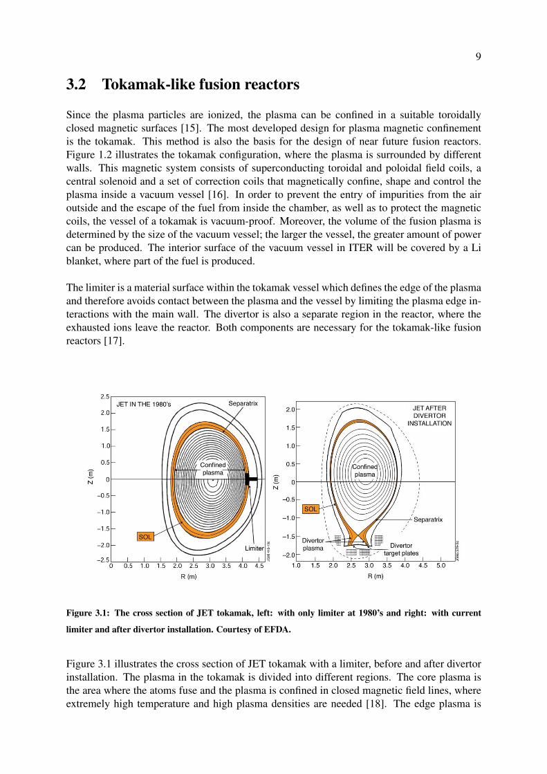
Figure 3.1: The cross section of JET tokamak, left: with only limiter at 1980’s and right: with current
limiter and after divertor installation. Courtesy of EFDA.
Figure 3.1 illustrates the cross section of JET tokamak with a limiter, before and after divertorinstallation. The plasma in the tokamak is divided into different regions. The core plasma isthe area where the atoms fuse and the plasma is confined in closed magnetic field lines, whereextremely high temperature and high plasma densities are needed [18]. The edge plasma is
10
cooler, while the hotter plasma is at the center; limiter and divertor materials are exposed to theedge plasma. The plasma that escapes the closed magnetic field lines is called exhaust and thelast flux surface that separates the closed field lines of the core plasma from the open ones ofthe edge plasma is the separatrix. The part of the edge plasma where particles will penetrateradially during their journey from the separatrix towards the walls is the scrape off layer (SOL).The SOL transports most of the exhaust to the divertor plates along the field lines [19].
The tokamak main wall and limiter components are mostly eroded in the limiter phase of theplasma; in current tokamaks with Be main wall and limiters, and future tokamaks with possiblyFe-based alloys main wall and limiters. In addition, these eroded particles with other impuritiestogether with high deuterium flux will be transported to and irradiate the divertor surface.
The erosion of PFCs can become a show-stopper by limiting the life time of components.Thus, choosing a proper material for divertor and limiter in future fusion reactor is highly crit-ical. ITER was originally planned to begin operations with a divertor target made of carbonfiber-reinforced carbon composite (CFC). CFC is a material that has high thermal conductivity.However, the CFC has recently been discarded as the divertor material due to excessive fuelretention (see section 3.3). Thereafter, the interests returned to using full metallic first wall,mainly W and Be. In 2011, JET started operating ITER-like wall (ILW), with Be for first wallmaterial and W for divertor region [20]. The similar decision has been done for ITER to explorethe full high-Z material configuration and Fe-based alloys for DEMO.
3.3 Nature of plasma-wall interaction
Plasma-wall interactions (PWIs) are among the most important challenges along the way toconstruct the future fusion reactor. In a fusion reactor, a very hot plasma (≈ 200 million degreesCelsius) is kept away from the wall of the chamber by using a strong magnetic field. However,this confinement cannot be perfect and the exhausted particles leave the reactor. Thus, the ionsfrom the edge plasma will hit the PFCs. These interactions may cause problems as they involvehigh heat and particle fluxes from plasma. Therefore, the best candidates for PFMs are onesthat are heat-resistant, thermally conductive, resistant to physical and chemical erosion, andshow low fuel retention.
These three crucial issues are the main PWI concerns [21] :1. Life time of PFMs.2. Dust production from eroded PFMs.3. Tritium(T) inventory in the vacuum vessel.
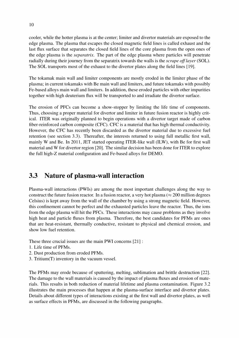
The PFMs may erode because of sputtering, melting, sublimation and brittle destruction [22].The damage to the wall materials is caused by the impact of plasma fluxes and erosion of mate-rials. This results in both reduction of material lifetime and plasma contamination. Figure 3.2illustrates the main processes that happen at the plasma-surface interface and divertor plates.Details about different types of interactions existing at the first wall and divertor plates, as wellas surface effects in PFMs, are discussed in the following paragraphs.
11
Figure 3.2: Schematic of complex plasma-surface interactions involving hydrogen (H), deuterium (D), tri-
tium (T), and gamma ray (γ) interactions with near-surface lattice atoms. Image reproduced from [23]
In fusion science, dust particles will mainly result from erosion of thick deposits or damagedwall components which are due to PWI processes. Dust is particles in the nanometer (nm) ormicrometer (µm) size range inside the vacuum vessel. Dust particles can result from variouserosion processes. Also the size of dust particles is important. Some of them are too heavy tobe moved by the plasma and tend to remain at the bottom of the vacuum vessel. They can beremoved by vacuum chamber cleaning during the shutdown period. In contrast, smaller dustparticles usually have a high sticking coefficient and make the cleaning procedure harder. SinceC is not a component of the divertor anymore, dust production plays a relatively minor role infusion devices and it seems not to be an operation hazard in comparison with the two otherPWI issues [24].
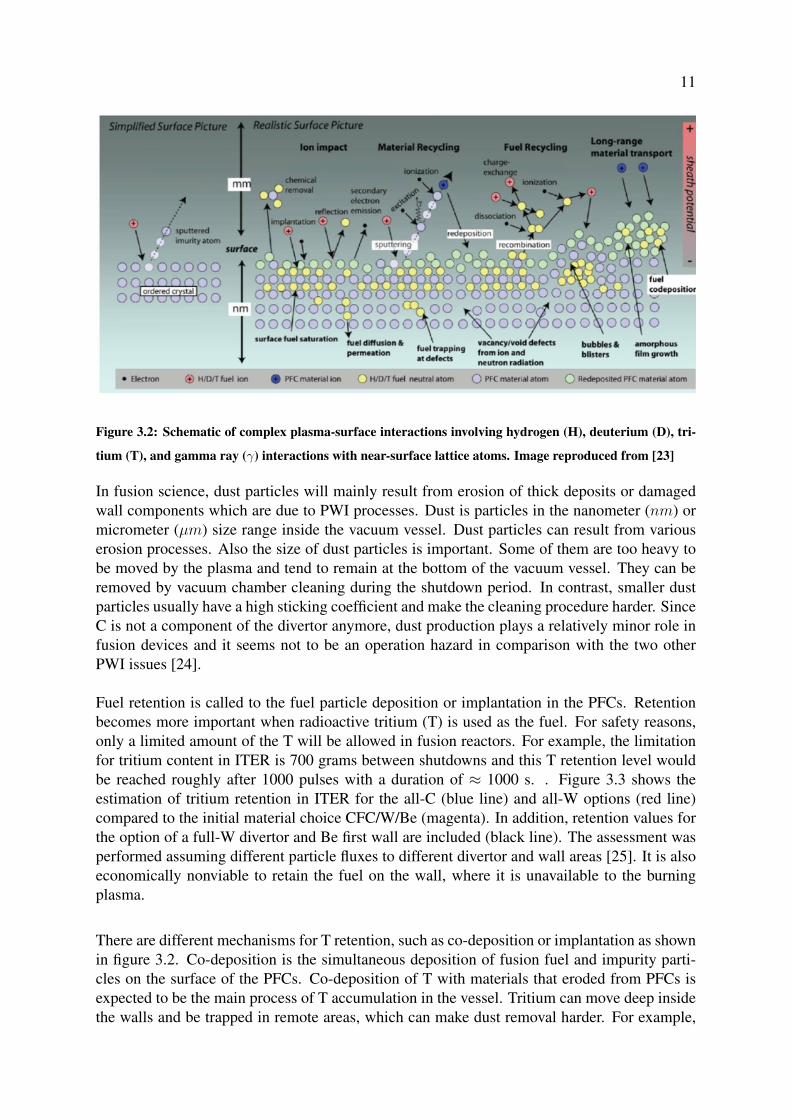
Fuel retention is called to the fuel particle deposition or implantation in the PFCs. Retentionbecomes more important when radioactive tritium (T) is used as the fuel. For safety reasons,only a limited amount of the T will be allowed in fusion reactors. For example, the limitationfor tritium content in ITER is 700 grams between shutdowns and this T retention level wouldbe reached roughly after 1000 pulses with a duration of ≈ 1000 s. . Figure 3.3 shows theestimation of tritium retention in ITER for the all-C (blue line) and all-W options (red line)compared to the initial material choice CFC/W/Be (magenta). In addition, retention values forthe option of a full-W divertor and Be first wall are included (black line). The assessment wasperformed assuming different particle fluxes to different divertor and wall areas [25]. It is alsoeconomically nonviable to retain the fuel on the wall, where it is unavailable to the burningplasma.
There are different mechanisms for T retention, such as co-deposition or implantation as shownin figure 3.2. Co-deposition is the simultaneous deposition of fusion fuel and impurity parti-cles on the surface of the PFCs. Co-deposition of T with materials that eroded from PFCs isexpected to be the main process of T accumulation in the vessel. Tritium can move deep insidethe walls and be trapped in remote areas, which can make dust removal harder. For example,

12
Figure 3.3: Estimation of in-vessel tritium retention in ITER for different plasma-facing materials. Image
reproduced from[21]
the erosion of carbon leads to the production of hydrocarbons and eventually results in theirre-deposition on the wall and in remote areas by trapping T. Co-deposition also occurs whenBe is used as the main wall of the reactor.T retention also happens by implantation mechanism where ions can go through the materialand implant there.
3.4 Ion irradiation of materials
In this section, the interaction of edge plasma with wall components is explained. PWIs consistof all kind of interactions between particles coming from plasma, such as high energy neu-trons or hydrogen, with every component of a reactor such as main wall components, breedingblanket and structural materials. Both surface and bulk effects can occur in components due tothese interactions. However, the present thesis focuses on plasma surface interactions (PSIs) inatomistic level that happen in the first wall of the reactor and the divertor region.
3.4.1 Nuclear stopping
When a bombarding ion enters a target, it experiences a series of collisions with target atomsuntil the ion stops at some depth in the target, which is called the penetration depth. The col-lisions between these atoms are governed by the interaction potential between them. Nuclear
13
stopping is elastic and the classical interaction between atoms drives from the attractive chem-ical binding between them and the repulsive Coulomb forces between nuclei. The energy Ttransferred from a projectile with mass M1 and kinetic energy E0 to a stationary atom withmass M2 in a collision can be solved by using the center of mass (CM) frame and calculatingthe scattering interaction [26, 27], which gives
T = 4M1M2
(M1 +M2)2E0 cos2 θ, (3.3)
where θ is the scattering angle. To calculate the magnitude of the nuclear stopping, the energytransfer cross section σ(E0, T ) can be used, where σ gives the probability of a collision withan energy transfer T. The energy transfer cross section can be constructed by the full trajecto-ries of colliding particles, which are determined from interaction potential between particles.Therefore, the path of colliding particles at all time must be such that the sum of the potentialand kinetic energies equals the kinetic energy of trajectories. The nuclear stopping power isthen given by
Sn(E0) = −dE0
dx
1
N=
∫ Tmax
Tmin
Tσ(E0, T )dT, (3.4)
where N is the atomic density.
3.4.2 Electronic stopping
Electronic stopping Se is caused by interaction between atomic projectiles and bound electrons.The slowing down mechanism is due to the inelastic collision between electrons in the targetand recoils going through it [28]. The energy lost by recoils is spent through the electron cloudinto thermal vibrations of the target atoms. This phenomenon is well known for very high en-ergy recoils, where the kinetic energy of recoil is on the order of MeV, while nuclear stoppingis dominant at lower recoil energies, especially for heavier projectiles. This phenomena is de-scribed well theoretically by the Bethe formula [29] for electronic stopping at high energies.For low kinetic energy range where the ion carries atomic electrons, the electronic stopping ofcharged ions is described by modern Bethe-Bloch theory [30].
For low energy recoils that are not completely ionized, it is more complicated to calculateSe theoretically [31]. By using Brandt-Kitagawa theory [32], the charge state of the ion istaken into account. Therefore, Se is best to be determined semi-empirically by correlating bothexperimental and theoretical values by using e.g. the SRIM/TRIM code tabulations [33, 34].
Figure 3.4 shows the ratio between nuclear and electronic stopping power. For light ions slow-ing down in heavy targets, the nuclear stopping power is weaker than the electronic at all energyranges.

14
Figure 3.4: Ratio between nuclear and electronic stopping power. The maximum of the nuclear stopping
curve is usually at energies between 10-100 keV, where as the electronic stopping power maximum is at
MeV energies [35].
3.4.3 Implantation
An incoming particle from the edge plasma is either implanted in the target material or backscateredduring an irradiation event. when an ion penetrates into a material and implants in a substrate.Different kind of phenomena may occur in the substrate, such as trapping, de-trapping, desorp-tion, bubble formation and so on.
The main wall and the divertor of a fusion reactor is constantly irradiated by a large H-isotopeflux coming from the edge plasma. Depending on the incoming ion energy and angle as well assubstrate temperature of the material, H ions either penetrate deep in the bulk or are implantednear the surface of material. As the incoming ion energy increases, H ions penetrate deeper inthe bulk and diffuse toward it as interstitials or get trapped in a defect which is created in thewall by the neutron irradiation and become immobile. In contrast, implanted H ions near thesurface can recombine to form H2 or hybrid molecules with the host surface atoms and releaseback to the surface as plasma impurities [36]. Furthermore, H ions mainly trap in defects andthe implanted H may agglomerate to form larger defects such as voids, bubbles and blisters (seesection 3.4.5) in solid materials [37]. Due to different characteristics of materials in defects andself-trapping, H bubble formation may happen in totally different depth in different materials.
Hydrogen isotope retention in plasma-facing materials due to implantation has been exten-sively studied for the JET device [38]. Different factors have been reported to affect H retentionin PFMs such as the presence of trapping impurities in materials, incoming particle flux andenergy and net damage in materials.
3.4.4 Reflection
Incoming ions from the plasma can be reflected back from the surface of the wall materialsand be injected back to the plasma. For energetic ions, the incident particle transfers its chargeand momentum and loses its energy to the target atom in a collision event and leaves the target

15
material after penetrating into a certain depth of the target material [39]. For lower incomingion energy ranges, the reflection happens close to surface and the ion does not penetrate deepinto the material. However, an ion is only reflected if the energy of the particle is above thebinding energy of the surface. One of the important factors which effect the incoming particlereflection coefficient Rn is the mass of the target materials. For example, R n for the 100 eV Dions is ≈ 0.4 in W, whereas the Rn for 100 eV D on Be was found to be 0.2 (Publication II).Moreover, increasing surface temperature lessens the amount of reflected D ions.
3.4.5 Erosion
Sputtering
The erosion of the PFCs surface is a highly critical issue [40]. Sputtering of materials is aprocess in which atoms or molecules are ejected from material’s surface due to the bombard-ment by incoming particles from the edge plasma [41]. The sputtering yield Y of the removedsurface atoms is determined by
Y =nsput
nimpacts
, (3.5)
where nsput represents the number of sputtered atoms and nimpacts represents the total numberof bombarded ions. Sputtering depends on a number of parameters such as mass ratio of in-cident particles to surface atoms, incoming particle energy and flux and angle of incident ion,as well as surface temperature [40]. Generally there are three main sputtering mechanisms:electronic sputtering, physical, and chemical sputtering.
Electronic sputtering occurs due to energetic electrons such as in a transition electron mi-croscopy or because of very high-energy ion bombardment, where the electronic excitationcan cause sputtering. However, the focus of this work is on physical and chemical sputtering.
Physical sputtering can happen in all materials independent of their structures. It results fromthe transfer of kinetic energy of the incoming particle to the target atoms on the surface layers.Bond breaking and therefore sputtering will happen if the energy received in the direction nor-mal to the surface is sufficient to overcome the surface binding energy SE [42]. Three regimesexist in this process: 1. If the energy is not enough to produce collision cascades, the sputteringoccurs as a single knock-off event. 2. A linear cascade event can happen when a few cascades,but no sub-cascades are created. 3. When the incoming ion is heavy enough, the collisionsoccur very close to each other. In this case the binary collision approximation (BCA) [43] isnot valid anymore (neither at low energies) and the collisional process should be understoodas a complicated process of many-body interactions between thousands of atoms. This phe-nomenon also causes a heat spike [44].
Chemical sputtering occurs when the incoming particles form chemical compounds with thesurface atoms by breaking and forming new bonds. Therefore, chemical sputtering is highlydependent on the surface materials and on the surface temperature, leading to processes suchas thermal desorption and evaporation. To prevent such processes, a cooling system should be

16
designed in the reactor’s first wall to control the wall’s temperature to be always safely belowa critical temperature. The erosion of hydrocarbons in fusion reactors is an examples of thechemical sputtering. On the other hand, molecules can form at the surface of certain materialsby swift chemical sputtering (SCS). In the SCS process, an energetic particle penetrates be-tween two substrate atoms, causing their bond to break, which release a surface atom togetherwith any other atom bound to it. Both C and Be experience SCS effect under low energy H iso-topes irradiation [45, 46]. The SCS played an important role during our studies for this thesisin the simulation of Be sputtering under low energy D irradiation (Publication III and IV).
Blistering
A large amount of PFMs can be eroded by the blistering phenomena under high irradiationfluxes and implantation fluences [47]. When irradiated ions are implanted in the target andagglomerate together, they displace the target atoms from their lattice sites, cluster together,and eventually form bubbles.This bubble formation near the surface in thick and loosely boundco-deposits can be observed as blisters [48]. Due to high ion gas pressure which is appliedin the same direction as irradiated ion, the blister is ruptured and the above layers fly off.In publication II, H-induced blister formation is reported at the depth of projected range. Infusion devices, this effect results in emission of wall materials which have a serious effects onthe power loss of the plasma.
Chapter 4
Methods
Several experimental devices exist to study the behavior of materials under irradiation in fusionreactors, such as small fusion reactors and linear plasma devices. However, the experimen-tal studies cannot always explain the exact mechanisms participating in the PWIs. Thereforemodelling can be used to complete the study of PWIs, building a bridge between theory andexperiments. Computer modelling has a very significant role in fusion research besides theexperimental studies in an extremely controlled condition. In this chapter, the basic princi-ples of classical molecular dynamics (MD), binary collision approximation (BCA) and kineticmonte carlo (KMC) are explained and briefly characterized. Special attention is paid to the MDinteraction models, which were used in all the publications of this thesis.
4.1 Classical Molecular Dynamics
Molecular dynamics (MD) is a simulation method based on solving classical equations of mo-tion for each atom in the system. Currently, MD can be used on systems with millions ofatoms. The popularity and applications of MD have been increased with increasing computa-tional power since its first use in the 1950’s [49]. In MD simulations the computational time isusually a linear function of the number of atoms in the system.
4.1.1 The MD algorithm
MD solves Newton’s equation of motion for atoms. It can be based on quantum-mechanicalinteractions, but the simulations used in this thesis are based on the classical MD method,the Born–Oppenheimer approximation [50]. This approximation states that the dynamics ofelectrons is so fast that they reach the equilibrium well before the nuclei do. Thus, the twosubsystems may be treated separately. The forces interacting between atoms are given by a socalled interatomic potential. The effect of the electrons is approximated as a single potentialenergy surface and electronic effects like the formation of atomic bonds, are included in theinteratomic potential which is used.
17
18
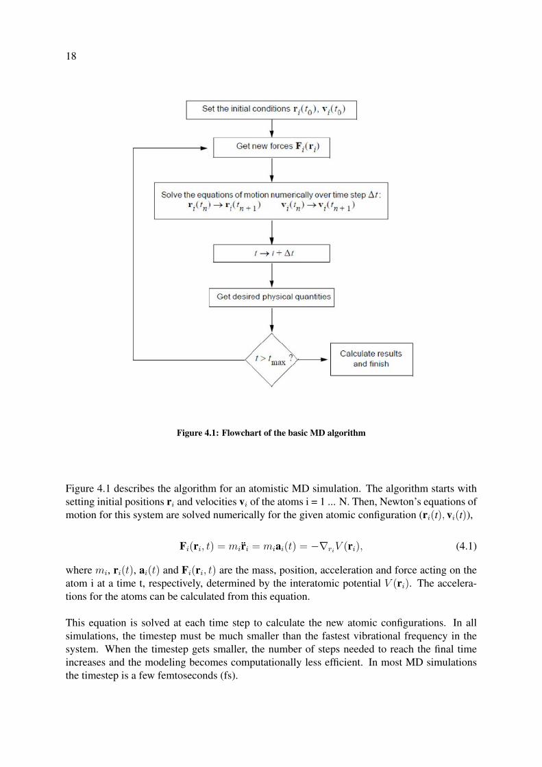
Figure 4.1: Flowchart of the basic MD algorithm
Figure 4.1 describes the algorithm for an atomistic MD simulation. The algorithm starts withsetting initial positions ri and velocities vi of the atoms i = 1 ... N. Then, Newton’s equations ofmotion for this system are solved numerically for the given atomic configuration (ri(t), vi(t)),
Fi(ri, t) = mir̈i = miai(t) = −∇riV (ri), (4.1)
where mi, ri(t), ai(t) and Fi(ri, t) are the mass, position, acceleration and force acting on theatom i at a time t, respectively, determined by the interatomic potential V (ri). The accelera-tions for the atoms can be calculated from this equation.
This equation is solved at each time step to calculate the new atomic configurations. In allsimulations, the timestep must be much smaller than the fastest vibrational frequency in thesystem. When the timestep gets smaller, the number of steps needed to reach the final timeincreases and the modeling becomes computationally less efficient. In most MD simulationsthe timestep is a few femtoseconds (fs).

19
The integrations of Eq. 4.1 are done numerically at each time step, using an accurate andefficient integrator algorithm. For example, the Gear 5 predictor-corrector algorithm [50] isemployed in the MD code PARCAS [51] used in this thesis to achieve numerically stable so-lutions. In a predictor-corrector method, first a prediction for the result is made and then thisresult is corrected in a second step. The corrector step can use different methods to refine theresult by using the old data. After computing the accelerations, the new positions for the atomscan be calculated. With the given timestep (∆t) the new predicted position can be calculated as
ri+1 = ri + vi∆t+1
2ai∆t
2 +1
6bi∆t
3 +1
24ci∆t4 +
1
120di∆t
5, (4.2)
where ri and vi are the old position and velocity, respectively, and ai is the calculated acceler-ation where bi, ci and di are the 3rd to 5th time derivative of ri, respectively. The new velocityof the atom is determined by
vi+1 = vi + ai∆t, (4.3)
After calculation of new positions and velocities, the list of nearby atoms for each atom in thesystem must be updated, usually done every ∼10 simulation steps.
Moreover, periodic boundary conditions (pbc) are used to simulate bulk materials and infinitelylong wires without having to simulate too many atoms. The substrate cells were created bythermalizing the desired structure representing the bulk structure of the material. In this config-uration, the pbc are applied in three (x, y and z) directions in this relaxation. Next, for openingthe surface of the cell and to prepare it for irradiation at z direction, the pbc are applied only inthe x and y directions.
Most often the temperature of the system must be controlled throughout the simulation. Therecan be a variation of the initial temperature of system; a cooling of the system to release theexcess of energy introduced by recoils, heating up to relax the system or the system is keptat constant temperature during the whole simulation. In this method, the initial temperatureis achieved by using Boltzmann distributed temperatures for all atoms, so all atoms will nothave exactly the same kinetic energy. In PARCAS, the temperature is controlled by using theBerendsen thermostat method [52]. Here the system temperature T is controlled by coupling itto an external heat bath at a temperature T0. Thus, the system’s temperature will relax expo-nentially to the desired T0 with a time constant τ ,
dT
dt=T0 − T (t)
τ, (4.4)
where T (t) is the temperature of the system at time t. In MD, this is implemented as a frictionterm in the equation of motion (Eq. 4.1), since the temperature of the system is defined by thevelocities of the atoms in it,
miai(t) = Fi(ri, t)−miγ(T0T− 1)vi, (4.5)

20
where τt = (2γ)−1 is the time constant. Therefore, the system temperature T is coupled to thedesired T0 by scaling the momentum of the particles by a damping constant λ, where
λ =
√1 +
∆t
τt(T0T− 1), (4.6)
In a similar way to the temperature control, the pressure control can be achieved by scaling thepositions instead of the velocities of atoms. Depending on the simulation setup, it is desiredto maintain the system at constant pressure and let the volume V of the simulation box fluctu-ate. To achieve this, the Berendsen pressure control [52] scales the atom coordinates and thesimulation cell dimensions by multiplying them by,
µ = 3
√1− ∆t
τP(P − P0), (4.7)
where P0 is the average pressure of the system, P is the desired pressure and τP is the timeconstant that determines the pressure scaling rate, as in the temperature control.
During our simulations, the temperature was controlled at all times; first, thermalizing thesubstrates while creating them, and later during the irradiation events in order to to remove theexcess energy introduced by the projectile. In contrast, the pressure control was only appliedwhen creating the substrates, while no pressure control was applied in the system during irra-diation events.
In PARCAS some of the electronic effects which has already been explained is included inthe algorithm. For instance, electronic stopping is modeled by scaling the recoil velocity ateach time step ∆t by
∆µ = ∆tSe
m, (4.8)
where Se is the electronic stopping and m is the recoil mass. During this thesis, Se is appliedto all atoms with a kinetic energy larger than 1.0 eV which are not eroded.
4.1.2 Interatomic Potentials
The result and accuracy of MD simulations depends on the forces acting between the atoms.Therefore, the most critical part of the MD simulation algorithm is the calculation of theseforces from the interatomic potential V (ri) (see Eq. 4.1). So, developing desired potentialmodels that can describe the interaction between atoms in a solid well, is vital. These po-tentials depend on different parameters. In general, they consist of attractive and repulsiveterms, to account for the attractive and repulsive interactions between electrons and nuclei,due to the different charge signs, at different interatomic distances. Although these potentialsare classical, their parametrization and formalism is usually derived from quantum mechanicalprinciples.

21
Brenner-Tersoff-like analytical bond-order potentials
An analytical bond-order potential (ABOP) is able to describe variations of the local chemicalenvironment, such as bond-breaking. Examples of ABOPs include the Tersoff potential [53],the Brenner potential [54], the Finnis-Sinclair potentials [55] and the second-moment tight-binding potentials [56]. The ABOPs were initially developed by Tersoff to describe covalentsolids, but it was shown by Brenner and Albe [57] to be extendable to metals.
For a Brenner-Tersoff like potential, the bonding strength between two atoms depends on thenumber of neighbors around, where more neighbors results in a weaker bond. Moreover, thereactivity of ABOPs can describe breaking and formation of bonds. This is important in anysystem with chemical reactions. Although, this can result in computationally expensive simu-lations. The total energy in a Brenner-Tersoff like ABOP is expressed as a sum over individualbond energies:
E =∑i>j
fij(rij)[V Rij (rij)−
Bij +Bji
2︸ ︷︷ ︸Bij
V Aij (rij)
], (4.9)
where rij is the distance between the atoms i and j, and V Rij (rij) and V A
ij (rij) are the repulsiveand attractive terms of the potential, respectively.These are pair potentials given by Morse-like terms,
V R(r) = D0
S−1exp(− β√
2S(r − r0)), (4.10)
V A(r) = SD0
S−1exp(− β
√2/S(r − r0)
), (4.11)
whereD0 is the dimer binding energy, r0 is the equilibrium bond distance and S is an adjustableparameter. The parameter β can be determined by the ground state oscillation frequency of thedimer.
The cut-off function fij(rij), defines the interaction range, which is usually restricted to thenearest neighbor and given by,
f(r) =
1, r ≤ R−D, (4.12a)1
2− 1
2sin[π(r −R)/(2D)], |R− r| ≤ D, (4.12b)
0, r ≥ R +D, (4.12c)
where R and D are parameters determining the cutoff range and interval, respectively.
The bond-order parameter Bij in Eq. 4.9, introduces the three-body interactions and angu-lar dependence to the potential,
Bij = (1 + χij)− 1
2 , (4.13)
22
whereχij =
∑k(6=i,j)
fik(rik)gik(θijk) exp[2µik(rij − rik)], (4.14)
Here, µik is a fitting parameter and again the cutoff function is included, while the indicesmonitor the type dependence of the parameters, which is important for the description of com-pounds. The angular function gik is of the form:
g(θijk) = γ
(1 +
c2
d2− c2
[d2 + (h+ cos θijk)2]
), (4.15)
where γ, c, d and h are adjustable parameters. In the case of c = 0, where the angular functionbecomes a constant, the total potential resembles an embedded atom method (EAM) potential,used to model the pure metal interaction. EAM potential is explained in details during thissection.
The ABOPs are suitable for studies regarding plasma–wall interactions in fusion reactors, sincethey are able to model non-equilibrium phenomena such as particle irradiation, sputtering andthe formation of mixed materials. They can describe pure metals such as Be and W well.Therefore, it is an appropriate tool to model the full W-C-Be-H system. This Brenner-Tersofflike potential was used for publications II-IV and is explained in Refs. [58, 59]. In publicationI to model the ternary Fe-C-D systems, the Brenner-Tersoff like potential which is suitablefor describing both metallic and covalent bonds, was used [60]. The potential calculation wasmodified in such a way that C-C, C-D and D-D parameters are given by Brenner’s secondparametrization [54], while for bonds involving Fe atoms, the Fe–C Tersoff potential [61] wasused.
The embedded atom method
The embedded atom method (EAM) is a model that is suitable for metals, where atoms aretreated to be planted in a sea of electrons [62]. The energy in EAM is expressed as a functionof the electron density,
E =∑i
Fi(ρi), (4.16)
where Fi is the embedding energy, and ρi is the electron density of an impurity at the atomsite i. To determine the term Fi, The Finnis-Sinclair solution [55] can be derived from second-momentum approximation of the tight-binding theory in solids [63],
Fi(ρi) = −A√ρi, (4.17)
where A is a fitting parameter.Practically, a correction term to represent the pair potential must be added to the total energyfor the short-range repulsive interaction. The total energy of a system is given by,
E =∑i
Fi
(∑j 6=i
ρj(rij)
)+
1
2
∑i,j 6=i
Vij(rij), (4.18)
23
The short-distance interaction
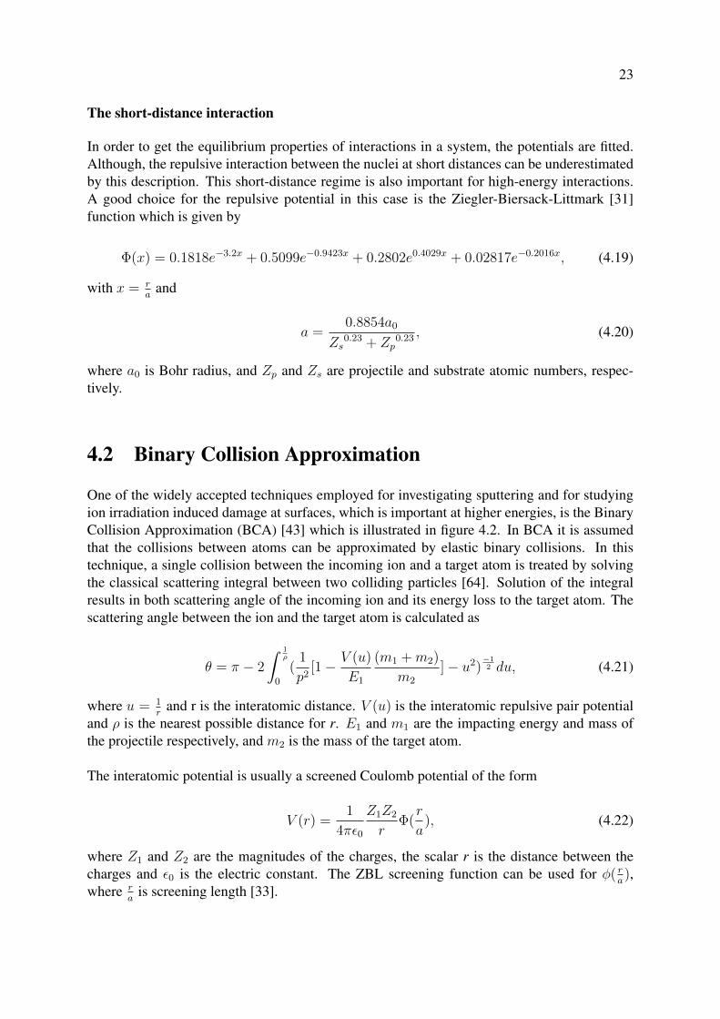
In order to get the equilibrium properties of interactions in a system, the potentials are fitted.Although, the repulsive interaction between the nuclei at short distances can be underestimatedby this description. This short-distance regime is also important for high-energy interactions.A good choice for the repulsive potential in this case is the Ziegler-Biersack-Littmark [31]function which is given by
Φ(x) = 0.1818e−3.2x + 0.5099e−0.9423x + 0.2802e0.4029x + 0.02817e−0.2016x, (4.19)
with x = ra
and
a =0.8854a0
Zs0.23 + Zp
0.23 , (4.20)
where a0 is Bohr radius, and Zp and Zs are projectile and substrate atomic numbers, respec-tively.
4.2 Binary Collision Approximation
One of the widely accepted techniques employed for investigating sputtering and for studyingion irradiation induced damage at surfaces, which is important at higher energies, is the BinaryCollision Approximation (BCA) [43] which is illustrated in figure 4.2. In BCA it is assumedthat the collisions between atoms can be approximated by elastic binary collisions. In thistechnique, a single collision between the incoming ion and a target atom is treated by solvingthe classical scattering integral between two colliding particles [64]. Solution of the integralresults in both scattering angle of the incoming ion and its energy loss to the target atom. Thescattering angle between the ion and the target atom is calculated as
θ = π − 2
∫ 1ρ
0
(1
p2[1− V (u)
E1
(m1 +m2)
m2
]− u2)−12 du, (4.21)
where u = 1r
and r is the interatomic distance. V (u) is the interatomic repulsive pair potentialand ρ is the nearest possible distance for r. E1 and m1 are the impacting energy and mass ofthe projectile respectively, and m2 is the mass of the target atom.
The interatomic potential is usually a screened Coulomb potential of the form
V (r) =1
4πε0
Z1Z2
rΦ(r
a), (4.22)
where Z1 and Z2 are the magnitudes of the charges, the scalar r is the distance between thecharges and ε0 is the electric constant. The ZBL screening function can be used for φ( r
a),
where ra
is screening length [33].
24
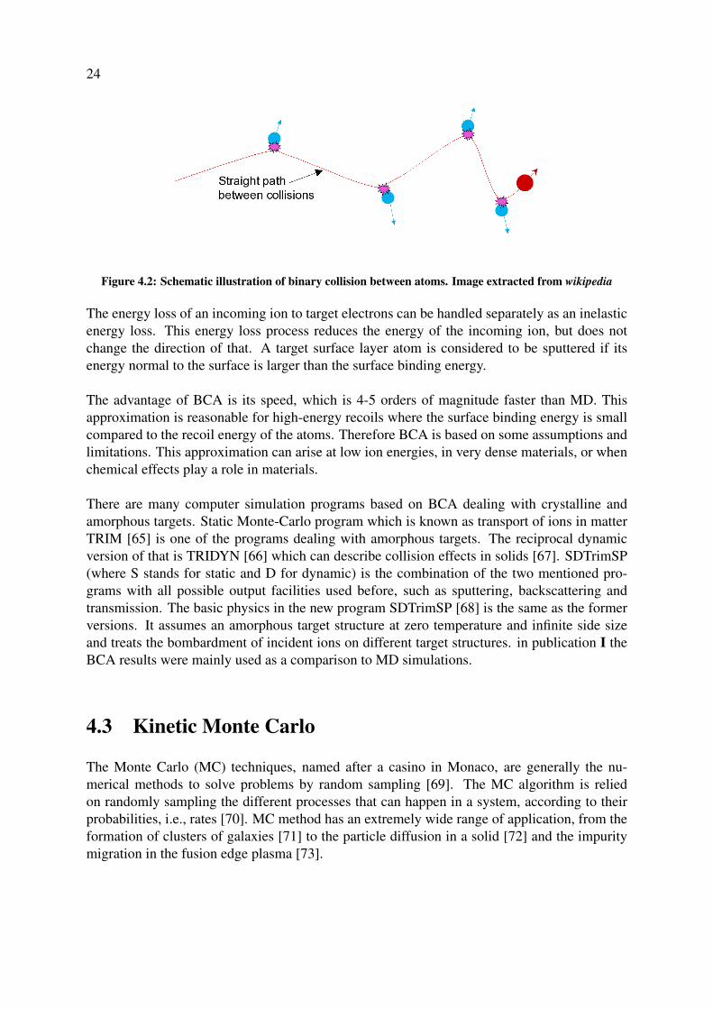
Figure 4.2: Schematic illustration of binary collision between atoms. Image extracted from wikipedia
The energy loss of an incoming ion to target electrons can be handled separately as an inelasticenergy loss. This energy loss process reduces the energy of the incoming ion, but does notchange the direction of that. A target surface layer atom is considered to be sputtered if itsenergy normal to the surface is larger than the surface binding energy.
The advantage of BCA is its speed, which is 4-5 orders of magnitude faster than MD. Thisapproximation is reasonable for high-energy recoils where the surface binding energy is smallcompared to the recoil energy of the atoms. Therefore BCA is based on some assumptions andlimitations. This approximation can arise at low ion energies, in very dense materials, or whenchemical effects play a role in materials.
There are many computer simulation programs based on BCA dealing with crystalline andamorphous targets. Static Monte-Carlo program which is known as transport of ions in matterTRIM [65] is one of the programs dealing with amorphous targets. The reciprocal dynamicversion of that is TRIDYN [66] which can describe collision effects in solids [67]. SDTrimSP(where S stands for static and D for dynamic) is the combination of the two mentioned pro-grams with all possible output facilities used before, such as sputtering, backscattering andtransmission. The basic physics in the new program SDTrimSP [68] is the same as the formerversions. It assumes an amorphous target structure at zero temperature and infinite side sizeand treats the bombardment of incident ions on different target structures. in publication I theBCA results were mainly used as a comparison to MD simulations.
4.3 Kinetic Monte Carlo
The Monte Carlo (MC) techniques, named after a casino in Monaco, are generally the nu-merical methods to solve problems by random sampling [69]. The MC algorithm is reliedon randomly sampling the different processes that can happen in a system, according to theirprobabilities, i.e., rates [70]. MC method has an extremely wide range of application, from theformation of clusters of galaxies [71] to the particle diffusion in a solid [72] and the impuritymigration in the fusion edge plasma [73].

25
4.3.1 Basic approach
One approach for simulation of the time evolution of a system by the MC method, is calledKinetic Monte Carlo (KMC). The main idea behind KMC is to use transition rates between thestates, formulated with the time increment.
The KMC algorithm starts by taking all the possible transitions of the system Ri and theirtransition rates ri should be listed and therefore the cumulative function is calculated accord-ingly,
Ri =i∑
k=1
rk, i = 1...N. (4.23)
In the next step, by generating a uniform random number, µ ∈ [0, 1], an event i is found forwhich
Ri−1 < µRN < Ri (4.24)
The chosen event i is carried out within the code and further consequences that event i mightlead to, are investigated. After that, the time t is updated, t → t + ∆t. ∆t is calculated bygenerating a new uniform random number ν ∈ (0, 1],
∆t = − ln(ν)
RN
, (4.25)
Finally, all the wanted properties of the system are calculated and the output is reported. Be-fore choosing a new event, all the rates and cumulative functionRi are updated. The mentionedsteps and algorithms are repeated until the desired number of events and time is reached.
KMC algorithm deals only with rates, therefore just by knowing the set of rates in a system, thesystem can be easily simulated without considering its thermodynamics. The big advantage ofKMC is that, as the cumulative function Ri is recalculated every step depending on the objectspresent in the system, the time scale ∆t of the steps will follow the system evolution automati-cally. The system can switch to shorter or longer time scale according to the remaining objectsin the system. For instance, if slow-moving objects are left in the system after fast-movingobjects have reacted and gone, the time scale will get automatically longer for the remainingobjects. Because of this feature of KMC, in many simulations, the initial time scale is of orderof fs, whereas the final one can be in the order of minutes or even years.
On the other hand, the main drawback of KMC is that all possible rates ri and possible re-actions need to be known in advance to develop a KMC algorithm. However, most of the ratescan be obtained from experimental data or calculated from other atomistic simulations methodssuch as BCA or MD, or, quantum mechanical calculations i.e. density functional theory (DFT)[74]. Another disadvantage of KMC might be from computational efficiency point of view dueto creating all the lists and recalculating ri in each time step, especially when there are a largenumber of possible transitions in the system.
26
4.3.2 Object Kinetic Monte Carlo
When the modeled processes in KMC are enforced for objects such as impurities, dislocationsor defects, the method is known as Object Kinetic Monte Carlo (OKMC). OKMC is one of thebest and preferred techniques to study defect evolution in solid materials [75, 76]. The modelassumes that there are several different states in a system and the transitions between thesestates are known and independent of time. These transitions are the input parameters of thealgorithm, and the dynamic evolution of the system out of equilibrium is followed by OKMC[77–79]. Since OKMC only takes into account defects (self-interstitial atoms, vacancies, im-purities and their clusters) but not the lattice atoms themselves, simulation boxes of the orderof few micrometers and large time scales of the order of hours (even days) can be simulated.Different OKMC algorithms exist, depending on the modelled processes, objects, probabilitiesand interactions. One of such models designed to study long term evolution of damage in irra-diated solids, for instance in fusion reactor materials, is called MMonCa [80].
In MMonCa, the objects are defined as defects that introduce undesired effects on materialapplications. MMonCa needs two sorts of input data: (i) an activation energy and a prefactorfor each transition that might happen, such as migration or dissociation of defects and (ii) theinitial positions of the defects present at the beginning of the simulation.
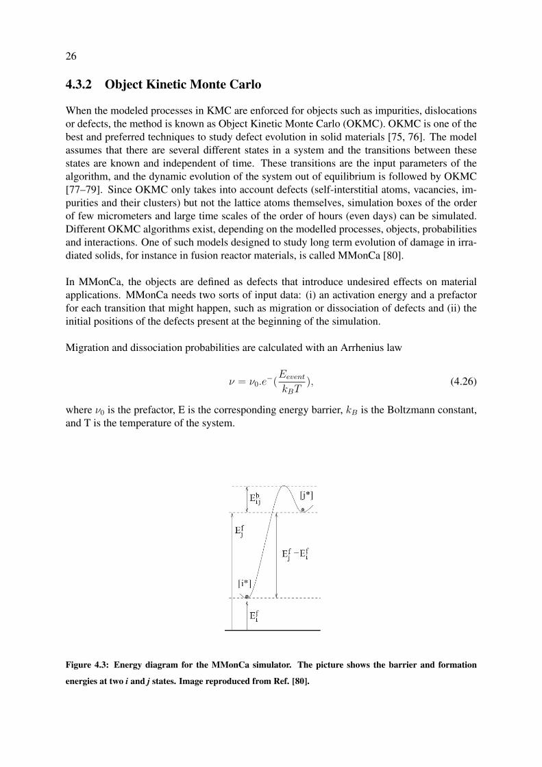
Migration and dissociation probabilities are calculated with an Arrhenius law
ν = ν0.e−(Eevent
kBT), (4.26)
where ν0 is the prefactor, E is the corresponding energy barrier, kB is the Boltzmann constant,and T is the temperature of the system.
Figure 4.3: Energy diagram for the MMonCa simulator. The picture shows the barrier and formation
energies at two i and j states. Image reproduced from Ref. [80].

27
The physical meaning of these energy barriers is illustrated in Fig. 4.3. In this simulator, defectevolution in solids is followed by three modules:1) objects or defects and all their possible transition rates and interactions2) computing time evolution by a rate manager3) creating spatial transitions and defect interactions by a space manager
Previously, the MMonCa has been successfully applied to study low energy helium irradiationon tungsten for a wide range of temperatures, to determine tungsten fuzz growth [81]. In thisthesis, in publication IV, we used MMonCa to investigate the effect of surface temperature onthe D depth profile in Be. The barrier for migration and formation of all mobile objects are ob-tained from literature, mostly with DFT calculations. In our OKMC simulations, many aspectsof D migrations and defect diffusion in ITER first-wall relevant conditions, were examined.

Chapter 5
Sputtering of Iron-based alloys for DEMO
applications
Various steels are being examined as PFMs for the main wall of DEMO. Since steels are alloysof Fe and C, it is highly critical to quantify the erosion of both elements when being exposed toplasma particles. In publication I the effect of D irradiation on ferrite, Fe with 1% C impurityand the cementite surface erosion and morphology changes was investigated. For that reason,cumulative bombardment of D ions on above mentioned surfaces was carried out by MD anddynamic BCA simulations varying impact energies and substrate temperatures. The exact de-tails of the simulation set up can be found in I. It should be noted that, during the simulations,an atom or cluster of atoms was considered sputtered and taken out of the system if they wereno longer bonded to the surface of the sample.
In general, the sputtering yield of both Fe and C were found to increase with impact energy.The effect of substrate temperature for the surfaces studied in I was found to be negligible.
Figure 5.1 illustrates Fe sputtering yields in pure Fe and Fe-1%C from MD and compared tothe experimental outcome by Hintz [82] and Bohdansky [83], varying impact energies. Thefigure shows excellent agreement between simulation and experiments.
We found that the number of reflected D atoms varied greatly with the impact energy andthe trapped D in Fe-based C-containing alloys forms D2 molecules. Moreover, in the Fe-1%Cand Fe3C simulation cells, C atoms where found to trap more D ions, which resulted in lowerD reflection in comparison with the pure Fe simulation cell at 500K. Figure 5.2 shows the frac-tion of D ions not implanted in the Pure Fe and Fe-1%C, simulation cells. For impact energieshigher than 100eV, a large fraction of irradiated D went through the simulation cell, and ionswere retained in the bulk.
Further, after a few hundred irradiations the Fe3C lattice started to lose its crystallinity in Drich areas, while the percentage of amorphous volume increases with increasing D influence.Moreover, the surface erosion is not homogeneous, which leads to surface roughening. These
28

29
Figure 5.1: A comparison of Fe sputtering yields in ferrite and Fe-1%C between MD simulation and exper-
iments at different impact energy. During the simulations the substrate temperature was set to 500K. From
publication I.
findings correlate well with previous MD study of cumulative irradiation of Fe3C with Fe re-coils [84]. As shown in Fig. 5.3, at energies higher than 70eV, D ions were implanted deeper inthe cell, forming D2 bubbles. For even higher energies, we predicted to see the same event thathappened in WC [85], where with increasing D influence, the D2 accumulation could result ina blistering-like effect. However the higher C percentage in the system simplifies the formationof D2 molecules in the system.
The key result of I is the preferential C sputtering during the bombardment in Fe3C speciallyin the 40-150eV energy range, where the surface was enriched with Fe. Figure 5.4 illustratesthat C sputtering dominates over Fe sputtering in cementite. However, the sputtered C atomswere mainly in atomic form and the number of each sputtered species after 3000 D impacts onFe3C at different energies are shown in a table in publication I. Analysing the sputtering mech-anism of Fe and C showed that it is dominantly of physical origin at impact energies higherthan 100eV, while at lower impact energies, the sputtering mechanism was of both physicaland chemical origin.
On the whole, the results in publication I show that if steels are used at PFMs, the existenceof C in them will cause chemical sputtering of C-containing molecules. Carbon transport andinventory calculations are required to assess whether this will lead to re-deposition of signifi-cant amounts of C during prolonged operation, and specially C-bound tritium, elsewhere in thereactor.

30
Figure 5.2: The D reflection of pure Fe at different temperatures and Fe-1%C at 500K as a function of
energy, obtained after 5000 cumulative D impacts. From publication I.
Figure 5.3: Structure of Fe3C after 3000 D impacts with different impact energies, for a substrate temper-
ature of 500K. Red, yellow and grey spheres represent Fe, C and D atoms, respectively. From publication
I.

31
Figure 5.4: Total Fe and C sputtering yield as a function of impact energy of Fe3C erosion by 3000 cumula-
tive D irradiation. From publication I.
Chapter 6
Co-bombardment of W and Be
In fusion reactors, to lessen the particle and local power load onto wall materials, impurityseeding to the plasma is needed as a method to remove excessive heat flux [86]. For instancein ITER, this can be achieved by puffing noble gas impurities in vacuum vessel manually [87].These plasma impurities interact with PFCs and can cause sputtering and modification of wallcomponents, as well as affecting both D release and retention in W and Be [88–90]. Theinteraction between plasma impurities such as D, Ne and Ar with W and Be using MD werestudied in publication II by irradiation of a mixture of x%Ar or Ne with (100-x)%D (x=0, 5, 10and 20) on both W and Be surfaces varying the impact energy and surface temperature. Furtherdetails regarding to the simulation set up and method can be found in publication II.
6.1 Impurity effects on sputtering
Overall, W and Be erosion yields were higher in the presence of Ar and Ne plasma impuritiesin comparison with pure D irradiation. The magnitude of sputtering yields increased with in-creasing impact energy, while the effect of substrate temperature for the surfaces studied herewas negligible.
W sputtering yields for pure D bombardments were zero for the cases studied here due tothe high energy threshold of D sputtering As shown in Fig. 6.1, adding a few percentage of im-purities to D ions can significantly affect W total sputtering yields, especially at higher energyof the impurity ions, which correlates well with previous experimental and modelling works[85, 88]. Moreover, the W molecular sputtering yield is really low, which is not enough forstatistical analysis. However the existence of multiple such events is still an important result,where the analysis confirmed that W-W bond breaking phenomena combined with the high en-ergies of the impurities means that the WD sputtering mechanism is likely physical rather thanchemical sputtering. Furthermore, impurity bombardment on the Be surface results in higherBe sputtering yields, and increasing the energy of impurity ion increased single Be sputteringyields (figure 6.2). The effect of impurities on BeDn molecular sputtering is less significantand most of the sputtered species were BeD molecules.
32

33
Figure 6.1: Total W sputtering yield as a function of impact energy at different surface temperature for
2000 (a) Ar-D and (b) Ne-D cumulative co-bombardment of W cells. From publication II.
A key result in II is that at impact energies lower than 50eV, adding noble gas impurities to Dbombardments would not significantly affect the W and Be erosion yield. Furthermore, sput-tering mechanism in low ion irradiation energy range is due to the swift chemical sputteringphenomenon, which means that Ar and Ne have very low probabilities to cause swift chemicalsputtering. However, noble gases affect the total erosion of both W and Be targets at impactenergies higher than 100 eV where physical sputtering is possible significantly. These find-ings correlate well with another MD modelling of H, He, Ne, Ar-bombardment of amorphoushydrocarbon structures, performed by P. Träskelin et. al. [91].
6.2 Materials modification
Deuterium reflection decreased with increasing ion energy in W and Be. This is simply dueto increased kinetic energy which makes it easier to penetrate into the material instead of re-flecting from the surface. During ion irradiation, the structure of both W and Be samples weredamaged. At energies of 50 eV and below, amorphization of the W and Be surfaces were ob-served as the irradiation went on, i.e. the deuterium ions gathered at the surface, changing thestructure from crystalline to non-crystalline due to the high concentration of deuterium.
For W simulations, at higher energies the surface itself remained almost completely intactduring pure D bombardment, with damage happening deeper in the lattice. However, when no-ble gas impurities were introduced, at higher impact energies the surface experienced notabledamage, it remained crystalline, but became much rougher. The amount of damage the sur-face received increased with both ion energy and impurity concentration. Figure 6.3 represents

34
Figure 6.2: Total Be sputtering yield as a function of impact energy at different surface temperature for
2000 (a) Ar-D and (b) Ne-D cumulative co-bombardment of Be cells. From publication II.
W surface structures at 800K surface temperature due to 10% Ne-90%D co-bombardmentsat different impact energies. The structures reflect that D penetrates deeper into the surfacewith increasing impact energy, and is spread over a wider area. There is also more deuterium,which is consistent with D reflection decreasing with ion energy. Furthermore, concentrationof noble gas impurities seems to have minimal effect on the D depth profile, except at higherenergies where increased impurity concentration seems to cause slight depletion of D at thesurface. Higher impurity concentrations lead to increasing D reflection yield, therefore thedamage caused to the surface prevents deuterium atoms from building up near the surface.
Moreover, in Be, for energies lower than 100eV, a large fraction of D atoms and almost all theirradiated noble gases were reflected back from surfaces. For ion impact energies higher than100eV, and therefore higher ion penetration depth, a large fraction of D atoms went through thesample and a small number of Ar and Ne atoms were also implanted, which results in observ-ing amorphization deeper in the simulation cells. For this energy range, the D clustered in thecenter of the cell, mainly forming D2 molecules. In a few cases, this D2 accumulation resultsin separation of a D2 layer, where the top layer of the cell was ruptured due to the high D2 gaspressure, which can apply a force in z direction (blistering-like effect). The layers above flewoff and the simulation was stopped in this case. However, surface rupture in W simulations wasnot observed here.

35
Figure 6.3: Surface morphology of W cells after 2000 10% Ne-90% D co-bombardments at different impact
energies, for surface temperature of 800K. The W atoms are represented by red spheres, D atoms and Ne
impurities are smaller light blue and yellow spheres, respectively. From publication II.

Chapter 7
Multi-scale modeling of Be erosion
As Be has been chosen for the main wall material of ITER, investigating the sputtering char-acteristics of the Be–D system is of vital importance. The purpose of publication III is to useMD techniques to gain insight into the effect of irradiation energy, particle flux and substratetemperatures on the Be erosion due to D irradiation under fusion relevant conditions. In thispublication special attention is paid to release of BeDn molecules. To estimate the stability ofBeDn molecules after sputtering, we also carried out quantum mechanical calculations of themolecules. Thermodynamic data for neutral BeDn gas molecules were calculated using differ-ent approaches [92, 93].
In general, the Be surface morphology showed significant change at different surface temper-atures under D irradiation with different energies. After only a few D impacts, the Be surfacewas damaged, the Be atoms had D atoms bound to them, and the deposition of D at the Besurface was able to cause surface amorphization at higher temperatures. Moreover, the erosionwas not homogeneous, leading to surface roughening. Be surface morphology changes dueto D irradiation is shown in figure 7.1. For the lowest substrate temperature (200K), the Datoms agglomerate in the center of the cell, mainly forming D2 molecules and become ratherimmobile. The D concentration in this area increased with increasing D fluence. At 600K, theimplanted D atoms migrated back and piled up around the surface, ending up mostly bound toBe atoms at the surface. At this temperature range, D could easily be desorbed when formingD2 molecules, increasing the fraction of D released in molecular form. With increasing temper-ature, the atomic motion at the surface increased, resulting in a higher probability for atomicbonds to break, and thus D was able to desorb before even having time to form D2 molecules.The highest temperature, 1440 K, is close to the Be melting point, leading to an increased Besputtering due to the increased atomic vibrations that weaken the atomic bonds at high temper-atures. At this temperature, around half of the cell was sputtered after 2000 D impacts.
We found that D implantation behaviour in Be at different surface temperatures highly affectsthe Be erosion behavior. As illustrated in figure 7.2, with increasing temperature, the Be sput-tering yield increased at low impact energies (<150eV). At temperatures higher than 600K,there was a sharp increase in the yields because of surface deuteration and desorption at thistemperature range. The molecular erosion showed a strong dependence on the topmost surface
36

37
Figure 7.1: Surface morphology of Be cells after 2000 impacts at different temperatures, for a particle flux
of 2.02*1024 (cm−2 s−1) (10 ps/impact). The D atoms are represented by small purple spheres and the Be
atoms are the larger pink spheres. From publication III.
D concentration. At temperature lower than 500K, the D concentration at the topmost layerand consequent molecular erosion are low, and the main eroded molecular species was seen tobe BeD. At higher temperatures (T≈ 600 K), because of high D surface concentration the totalsputtering yield of Be atoms increased rapidly and BeD2 and BeD3 molecules became the maineroded species, reducing the sputtered BeD:Be fraction. However, we studied the stability anddissociation of the larger molecules and found that the BeDn molecules would dissociate assoon as they entered the edge plasma, mainly forming atomic Be and D2 molecules, and notcontributing significantly to the signals measuring the fraction of Be eroded as BeD. At evenhigher temperatures (T > 1000K), the Be was eroded in atomic form and as BeD molecules.These findings are presented in figure 7.3, and the simulated temperature dependence of theBeD release was in agreement with experiments performed at JET, which showed a linear dropin the BeD:Be ratio, i.e. Be sputtered as BeD, with increasing temperature in the range of500–700K [94].
Our study in publication III, MD simulation of cumulative D impacts on Be surfaces, showeda complex outcome for molecular erosion. Due to very different D surface content at differ-ent surface temperatures, larger Be–D molecules were also emitted when the D concentrationincreased in the topmost layer. These results were non-physical for reactor-like conditions,caused by MD being limited to short time scales, and consequently high irradiation fluxes [95].Therefore, the purpose for publication IV was to investigate erosion of equilibrium Be surfaces,in a KMC-MD multi-scale approach. The complex relationship between surface temperatureand D surface content was appropriately calculated by a longer time-scale approach, the KMCtechnique. The KMC outcome provides initial substrate structures for MD closer to experimen-tal condition, which allows gaining insight into the effect of surface temperature and irradiationenergy on Be erosion.
In our OKMC simulations, many aspects of D migrations and defect diffusion in ITER first-wall relevant conditions, were examined. Eventually, the D distribution profiles at different
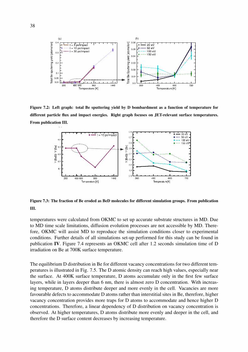
38
Figure 7.2: Left graph: total Be sputtering yield by D bombardment as a function of temperature for
different particle flux and impact energies. Right graph focuses on JET-relevant surface temperatures.
From publication III.
Figure 7.3: The fraction of Be eroded as BeD molecules for different simulation groups. From publication
III.
temperatures were calculated from OKMC to set up accurate substrate structures in MD. Dueto MD time scale limitations, diffusion evolution processes are not accessible by MD. There-fore, OKMC will assist MD to reproduce the simulation conditions closer to experimentalconditions. Further details of all simulations set-up performed for this study can be found inpublication IV. Figure 7.4 represents an OKMC cell after 1.2 seconds simulation time of Dirradiation on Be at 700K surface temperature.
The equilibrium D distribution in Be for different vacancy concentrations for two different tem-peratures is illustrated in Fig. 7.5. The D atomic density can reach high values, especially nearthe surface. At 400K surface temperature, D atoms accumulate only in the first few surfacelayers, while in layers deeper than 6 nm, there is almost zero D concentration. With increas-ing temperature, D atoms distribute deeper and more evenly in the cell. Vacancies are morefavourable defects to accommodate D atoms rather than interstitial sites in Be, therefore, highervacancy concentration provides more traps for D atoms to accommodate and hence higher Dconcentrations. Therefore, a linear dependency of D distribution on vacancy concentration isobserved. At higher temperatures, D atoms distribute more evenly and deeper in the cell, andtherefore the D surface content decreases by increasing temperature.

39
Figure 7.4: OKMC simulation cell after D irradiation at 700K surface temperature.
The key result of this OKMC simulation is that a strong temperature dependency of D concen-tration on the number of vacancies is observed during the simulations. At the early stages ofour simulation, all vacancies were filled with up to 5 D atoms and all other incoming D atomsdiffused in the cell as interstitial. D atoms tend to accommodate in a vacant site rather thanbecoming interstitial. As the simulation goes on, at lower temperatures, D atoms remain invacancies and form immobile D5V defects. At higher temperatures, D atoms are de-trappedfrom vacancies regularly because of their lower binding energy and diffuse fast toward bulk asan interstitial.
The final D profiles at 5% vacancy concentration (reasonable for mixed crystalline, and co-and re-deposited layers) to set up accurate substrate structures in MD at different temperaturesare shown in figure 7.6.
Figure 7.5: Equilibrium D distribution in Be for different vacancy concentration at 400 K (left) and 700 K
(right). The number of D atoms in different layers is normalized to the number of Be atoms in bulk. From
publication IV.

40
Figure 7.6: Equilibrium D distribution in Be at 5% vacancy concentration to set-up MD initial structures
at different surface temperatures. From publication IV.
In the MD part of the work, there was no interest in further evolving the surfaces and hence thenon-cumulative simulations were performed. With increasing surface temperature and hencereduced D surface concentration, the erosion yield of Be increased within the error bar, for ionenergies greater than 10 eV. At lower surface temperatures where D concentrations are higher(there are more D neighbours to surface Be atoms), the probability of hitting a Be atom withincoming ion is lower than higher surface temperature, which leads to lower total Be erosionyield. With increasing impact energy, the total Be erosion yield increases with temperature,where it peaks at 100eV. For energies higher than 100eV, a reduction in total yield is observed,which is due to larger penetration depth of D ions at higher energies, which lowers the surfaceinteractions.
A comparison of modelled and measured total Be sputtering yield at 300K surface tempera-ture as a function of incident ion energy is presented in figure 7.7. The experimental yieldswere measured in PISCES-B facility, using a polycrystalline Be sample [96]. The differencebetween MD and experimental total Be yields is considerable, especially for impact energieshigher than 60eV. However, the experimental yields still follow the same trend as in MD simu-lations.
The fraction of Be atoms that are sputtered as BeD molecules is illustrated in figure 7.8. In-creasing both surface temperature and impact energy lead to a reduction of the BeD erosionyield. At higher temperatures and hence lower D concentration, there are less D atoms thanwhat is initially bound to Be atoms, which lead to lower BeD erosion yield. Moreover, as theimpact energy increases, single Be atoms are eroded via physical sputtering rather than swiftchemical sputtering, lowering the BeD molecular fraction.

41
Figure 7.7: Comparison of modeled (by MD) and measured (by PISCES-B) total Be sputtering yield by D
irradiation as a function of impact energies at 300 K surface temperature. The Eckstein fit is also plotted
by a factor of 0.5. From publication IV.
Figure 7.8: The fraction of Be eroded as BeD molecules as a function of surface temperatures for different
impact energies. From publication IV.
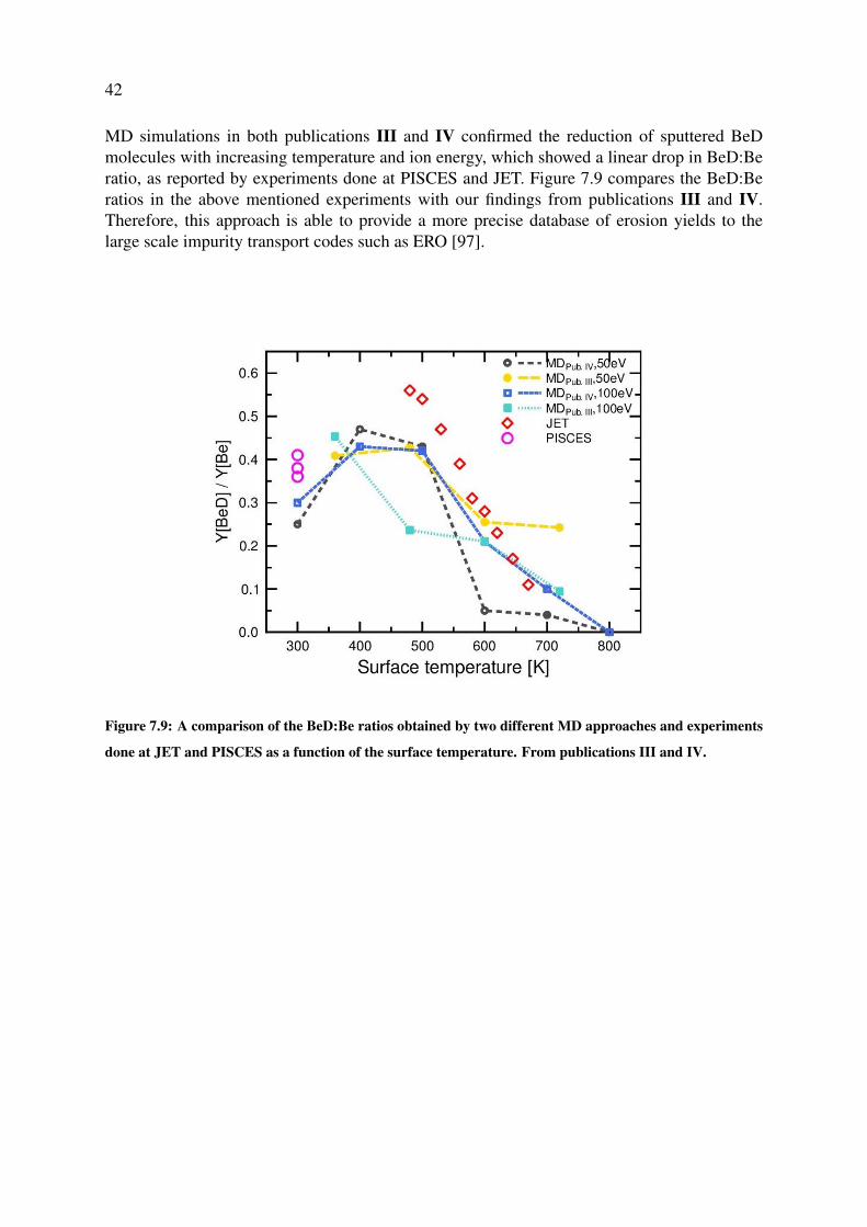
42
MD simulations in both publications III and IV confirmed the reduction of sputtered BeDmolecules with increasing temperature and ion energy, which showed a linear drop in BeD:Beratio, as reported by experiments done at PISCES and JET. Figure 7.9 compares the BeD:Beratios in the above mentioned experiments with our findings from publications III and IV.Therefore, this approach is able to provide a more precise database of erosion yields to thelarge scale impurity transport codes such as ERO [97].
Figure 7.9: A comparison of the BeD:Be ratios obtained by two different MD approaches and experiments
done at JET and PISCES as a function of the surface temperature. From publications III and IV.

Chapter 8
Summary
In this dissertation, the plasma surface interactions expected in the first wall of a fusion reactorhave been investigated by several atomistic simulation methods.
First, the viability of iron-based alloys for steel as wall material was studied. The surfaceerosion and morphology changes due to deuterium irradiation were investigated. Fe sputteringyield had a positive correlation with impact energy, while the effect of substrate temperature forthe surfaces studied here was negligible. In iron carbide, because of C preferential sputteringduring the irradiation, the surface was enriched with Fe. Analysing the sputtering mechanism ofFe and C showed that at lower impact energies, the sputtering mechanism was of both physicaland chemical origin while at energies higher than 100 eV, the physical sputtering dominated.Furthermore, the initial lattice structure was observed to become completely amorphised at theD implantation zone, and the trapped D in iron-based carbon-containing alloys was found toform D2 molecules. In general, we found that if steels are used as plasma-facing material, theexistence of C in them will lead to chemical sputtering. C transport and inventory calculationsare therefore needed to quantify the amount of C in reactor.
The effect of plasma impurity co-bombardment (D, Ar and Ne) on sputtering and surface mor-phology of W and Be was also studied. Special attention was paid to the magnitude of W andBe erosion yields due to the existence and varying the fraction of irradiated Ar and Ne impu-rities. Overall, W and Be sputtering yields were higher in the presence of Ar and Ne plasmaimpurities in comparison with pure D ion irradiation, and its magnitude increased with increas-ing impact energy, while the effect of substrate temperatures for the surfaces studied here wasnegligible. However, noble gases affect significantly the total erosion of both W and Be targetsat impact energies higher than 100 eV, where physical sputtering is possible. In both materials,after a few hundred bombardments the sample surface was damaged, and cell structures hadchanged from crystalline to amorphous at lower ion energy, and blistering-like effect was ob-served due to D2 accumulation in Be cells at higher energies.
The main part of this dissertation concerned the effect of reactor-relevant parameters on Beerosion and surface morphology. For that purpose, the study was started with a cumulative Dirradiation on Be by MD, scanning over different parameters. We found that the D implantation
43
44
and Be surface morphology varied greatly with temperature. The molecular erosion showed astrong dependence on the topmost surface D concentration. The simulated temperature depen-dence of the BeD release was in agreement with experiments performed at JET, which showeda linear drop in the BeD:Be ratio, i.e., Be sputtered as BeD, with increasing temperature inthe range of 500–700 K. However, due to very different D surface contents at different tem-peratures, large amounts of BeD2 and BeD3 molecules were emitted, where these results werenon-physical for reactor-like conditions, caused by the MD limitation in time. Therefore, wedesigned a KMC-MD multi-scale approach to investigate Be erosion in an equilibrated sur-face that the KMC outcome provides initial substrate structures for MD closer to experimentalconditions. KMC simulations provided a D surface concentration profile for any surface tem-perature and incoming D energy. The results revealed a strong dependence of the D surfacecontent on temperature. Increasing the surface temperature leads to a lower D concentration atthe surface, because of the tendency of D atoms to avoid being accommodated in a vacancy,and de-trapping from impurity sites and hence diffuse fast toward bulk. At the next step, theKMC D profile was implemented as a starting configuration in MD simulations, and then totaland molecular Be erosion yields due to D irradiation were analysed. Increasing the temperatureand impact energy was found to decrease the fraction of Be atoms that were sputtered as BeDmolecules due to the lower D surface concentrations at higher temperatures. These findingscorrelate well with different experiments performed at the JET and PISCES-B devices.
The mechanisms and processes identified during this dissertation improve the understandingof plasma surface interactions, such as erosion and implantation and their effect on the fu-sion reactor main wall. The database obtained from this work is helpful for gaining insight onthe erosion and re-deposition, along with emission profile and chemical erosion of molecules,which are then accurately modelled by larger scale codes such as ERO calculations. It is there-fore necessary to continue with the atomistic simulation of plasma-facing materials, scanningover different and wider parameter ranges, together with and in comparison to other modellingmethods and experiments.

Acknowledgments
I wish to thank the former head of the Department of Physics at the University of Helsinki,Prof. Juhani Keinonen, and the current head, Prof. Hannu Koskinen, as well as the head ofthe Accelerator Laboratory, Prof. Jyrki Räisänen, for providing the facilities for the researchpresented in this thesis. Financial support from the EFDA, TEKES-EURATOM and the MA-TRENA are greatly appreciated.
I’m deeply grateful to my supervisor, Prof. Kai Nordlund, for the motivation and positiveattitude. Thank you for providing both support and freedom, and a wonderful atmosphere inwhich to work. From you I have learned a lot. I am also thankful to Dr. Carolina Björkas andDr. Ane Lasa for your guidance, effort and determination for a well done work and fruitfuldiscussions.
I would also like to thank my colleagues and friends at the lab that make the lab far morethan a working place. Thank you Jussi for your unconditional help and friendship and for al-ways being there for me; Antti for your calm attitude and answering any question with yoursmile anytime I asked. I also would like to thank my office-mates during the last four years;Caro, Ane, Jussi, Alma, Andrea and Junlei.
My time in Finland has been far from student life. I am truly thankful to all my friends spe-cially Hilal for her unconditional support. I wish to thank my parents and my brothers for theirlove, trust, motivating me and unlimited support during my whole life and even from thousandskilometres away.
Helsinki, October 24th, 2017
45

Bibliography
[1] International Energy Agency. Key World Energy Statistics.www.iea.org/publications/freepublications/publication/KeyWorld2016.pdf.
[2] Burn An energy journal. The connection between greenhouse gases, climate change,and global warning. www.burnanenergyjournal.com/the-connection-between greenhouse-gases-climate-change-and-global-warming.
[3] Paul Mobbs The Free Rang Network. Renewable energy, the potential and the limitations.www.fraw.org.uk/mei/archive/handouts/e-series/e04/e04-renewable-energy.html.
[4] The Joint European Torus. www.jet.efda.org.
[5] D-T Fusion. Science learning. www.legacy.sciencelearn.org.nz/Contexts/Gases-and-Plasmas/Sci-Media/Images/D-T-fusion.
[6] W. J. Nuttall. Fusion as an energy source: Challenges and opportunities. Institute ofPhysics: Report, 2008.
[7] ITER Physics Basis Editors and ITER Physics Expert Group Chairs and Co-Chairs andITER Joint Central Team and Physics Integration Unit. Iter physics basis. Nuclear Fusion,39:2137–2638, 1999.
[8] D. Kh. Morozov, E. O. Baranova, and I. Yu. Senichenkov. Impurity radiation from atokamak plasma. Plasma Physics Report, 22:906–922, 2007.
[9] D. J. Ward and S. L. Dudarev. Economically competitive fusion. Materials Today,11(12):46, 2008.
[10] R. A. Pitts, S. Carpentier, F. Escourbiac, T. Hirai, V. Komarov, S. Lisgo, A. S. Kukushkin,A. Loarte, M. Merola, A. Sashala Naik, R. Mitteau, M. Sugihara, B. Bazylev, and P. C.Stangeby. A full tungsten divertor for ITER: Physics issues and design status. Journal ofNuclear Materials, 438:S48–S56, July 2013.
[11] G. Federici. Plasma wall interactions in ITER. Physica Scripta Volume T, 124:1–8, May2006.
[12] Preparing For ITER and Developing DEMO https://www.euro-fusion.org/programme/.
[13] G. Janeschitz, ITER JCT, and HTs. Plasma-wall interaction issues in iter. Journal ofNuclear Materials, 290-293:1–11, 2001.
46

47
[14] A. W. Kleyn, N. J. Lopez Cardazo, and U. Samm. Plasma-surcace interaction in thecontext of iter. Physical Chemistry Chemical Physics, 8:1761–1774, 2006.
[15] Rainer Behrisch. Plasma-facing materials for fusion devices. Journal of Surface Investi-gation. X-ray, Synchrotron and Neutron Techniques, 4(4):549–562, 2010.
[16] The ITER Organization http://www.iter.org/.
[17] T. N. Todd and C. G. Windsor. Progress in magnetic confinement fusion research. Con-temporary Physics, 39(4):255–282, 1998.
[18] B J Green, ITER International Team, and Participant Teams. Iter: burning plasma physicsexperiment. Plasma Physics and Controlled Fusion, 45(5):687, 2003.
[19] et. al. B. Lipschultz. Plasma–surface interaction, scrape-off layer and divertor physics:implications for iter. Nuclear Fusion, 47(9):1189, 2007.
[20] G F Matthews, M Beurskens, S Brezinsek, M Groth, E Joffrin, A Loving, M Kear, M-LMayoral, R Neu, P Prior, V Riccardo, F Rimini, M Rubel, G Sips, E Villedieu, P de Vries,M L Watkins, and EFDA-JET contributors. Jet iter-like wall—overview and experimentalprogramme. Physica Scripta, 2011(T145):014001, 2011.
[21] et. al. J. Roth. Recent analysis of key plasma wall interactions issues for {ITER}. Journalof Nuclear Materials, 390–391:1 – 9, 2009. Proceedings of the 18th International Confer-ence on Plasma-Surface Interactions in Controlled Fusion DeviceProceedings of the 18thInternational Conference on Plasma-Surface Interactions in Controlled Fusion Device.
[22] V Philipps, P Wienhold, A Kirschner, and M Rubel. Erosion and redeposition of wallmaterial in controlled fusion devices. Vacuum, 67(3–4):399 – 408, 2002. 7th EuropeanVacuum Meeting/3rd European Topical Conference on Hard Coatings.
[23] Steven J. Zinkle. Challenges in developing materials for fusion technology - past, presentand future. Fusion Science and Technology, 64(2):65–75, 2013.
[24] S. Brezinsek, T. Loarer, V. Philipps, H.G. Esser, S. Grünhagen, R. Smith, R. Felton,J. Banks, P. Belo, A. Boboc, J. Bucalossi, M. Clever, J.W. Coenen, I. Coffey, S. De-vaux, D. Douai, M. Freisinger, D. Frigione, M. Groth, A. Huber, J. Hobirk, S. Jach-mich, S. Knipe, K. Krieger, U. Kruezi, S. Marsen, G.F. Matthews, A.G. Meigs, F. Nave,I. Nunes, R. Neu, J. Roth, M.F. Stamp, S. Vartanian, U. Samm, and JET EFDA contribu-tors. Fuel retention studies with the iter-like wall in jet. Nuclear Fusion, 53(8):083023,2013.
[25] G. De Temmerman, M.J. Baldwin, R.P. Doerner, D. Nishijima, and K. Schmid. An em-pirical scaling for deuterium retention in co-deposited beryllium layers. Nuclear Fusion,48(7):075008, 2008.
[26] K. Nordlund, N. Runeberg, and D. Sundholm. Repulsive interatomic potentials calculatedusing Hartree-Fock and density-functional theory methods. Nucl. Instr. Meth. Phys. Res.B, 132:45–54, 1997.
[27] Gary S. Was. Springer Berlin Heidelberg, 2007.

48
[28] J. Lindhard, M. Scharff, and H. E. Schiøtt. Range concepts and heavy ion ranges. Kgl.Danske Vid. Selskab, Mat.- Fys. Medd., 33 (14):1–42, 1963.
[29] H. Bethe. Zur theorie des durchgangs schneller korpuskularstrahlen durch materie. An-nalen der Physik, 397(3):325–400, 1930.
[30] J. F. Ziegler. Stopping of energetic light ions in elemental matter. J. Appl. Phys.,85(3):1249, 1999.
[31] J. F. Ziegler, J. P. Biersack, and U. Littmark. The Stopping and Range of Ions in Matter.Pergamon, New York, 1985.
[32] Werner Brandt and M. Kitagawa. Effective stopping-power charges of swift ions in con-densed matter. Phys. Rev. B, 25(9):5631, 1982.
[33] J. F. Ziegler, J. P. Biersack, and M. D. Ziegler. SRIM - The Stopping and Range of Ions inMatter. SRIM Co., Chester, Maryland, USA, 2008.
[34] J. F. Ziegler. SRIM-2013 software package, available online at http://www.srim.org.
[35] K. Nordlund. Energy loss of energetic ions , available at http://beam.helsinki.fi/ knord-lun/mdh/rangetext.html.
[36] R.A. Anderl, R.A. Causey, J.W. Davis, R.P. Doerner, G. Federici, A.A. Haasz, G.R.Longhurst, W.R. Wampler, and K.L. Wilson. Hydrogen isotope retention in berylliumfor tokamak plasma-facing applications. Journal of Nuclear Materials, 273(1):1 – 26,1999.
[37] J.B. Condon and T. Schober. Hydrogen bubbles in metals. Journal of Nuclear Materials,207:1 – 24, 1993.
[38] C. H. Skinner, A. A. Haasz, V. Kh. Alimov, N. Bekris, R. A. Causey, R. E. H. Clark, J. P.Coad, J. W. Davis, R. P. Doerner, M. Mayer, A. Pisarev, J. Roth, and T. Tanabe. Recentadvances on hydrogen retention in iter’s plasma-facing materials: Beryllium, carbon, andtungsten. Fusion Science and Technology, 54(4):891–945, 2008.
[39] C.H. Wu and North Atlantic Treaty Organization. Scientific Affairs Division. HydrogenRecycling at Plasma Facing Materials. NATO science series: Mathematics, physics, andchemistry. Springer Netherlands, 2000.
[40] J. Roth. Review and Status of Physical Sputtering and Chemical Erosion of Plasma FacingMaterials, pages 203–224. Springer Berlin Heidelberg, Berlin, Heidelberg, 2005.
[41] R. Behrisch and W. Eckstein (ed.). Sputtering by Particle Bombardment: Experimentsand Computer Calculations from Threshold to MeV Energies. Springer, Berlin, 2007.
[42] P. Sigmund. Mechanisms and theory of physical sputtering by particle impact. Nucl. Instr.Meth. Phys. Res. B, 27:1, 1987.
[43] M. T. Robinson and Ian M. Torrens. Computer simulation of atomic-displacement cas-cades in solids in the binary-collision approximation. Phys. Rev. B, 9(12):5008, 1974.

49
[44] Dirk Naujoks. Plasma-material interaction in controlled fusion, volume 39. SpringerScience & Business Media, 2006.
[45] K. Nordlund, E. Salonen, A. V. Krasheninnikov, and J. Keinonen. Swift chemical sput-tering of covalently bonded materials. Pure and Applied Chemistry, 78(6):1203–1212,2006.
[46] C. Björkas, K. Vörtler, K. Nordlund, D. Nishijima, and R. Doerner. Chemical sputteringof be due to d bombardment. New Journal of Physics, 11:123017, 2009.
[47] Rainer Behrisch and K Wittmaack. Sputtering by particle bombardment, volume 1.Springer Berlin, 1981.
[48] YU. V. Martynenko. The theory of blister formation. Radiation Effects, 45(1-2):93–101,1979.
[49] B. J. Alder and T. E. Wainwright. Studies in Molecular Dynamics. I. General Method. J.of Chem. Phys., 31(2):459, 1959.
[50] M. P. Allen and D. J. Tildesley. Computer Simulation of Liquids. Oxford University Press,Oxford, England, 1989.
[51] K. Nordlund, 2016. PARCAS computer code. The main principles of the molecular dy-namics algorithms are presented in [? ? ]. The adaptive time step and electronic stoppingalgorithms are the same as in [? ]. The 2016 version of the code is published in thesupplementary material to Ref. [? ].
[52] H. J. C. Berendsen, J. P. M. Postma, W. F. van Gunsteren, A. DiNola, and J. R. Haak.Molecular dynamics with coupling to external bath. J. Chem. Phys., 81(8):3684, 1984.
[53] J. Tersoff. New Empirical approach for the structure and energy of covalent systems.Phys. Rev. B, 37:6991, 1988.
[54] Donald W. Brenner. Empirical potential for hydrocarbons for use in simulating the chem-ical vapor deposition of diamond films. Phys. Rev. B, 42(15):9458, 1990. ; idem, 46, 1948(1992).
[55] M. W. Finnis and J. E. Sinclair. A simple empirical N-body potential for transition metals.Phil. Mag. A, 50(1):45, 1984. see also Erratum, ibid. 53 (1986) 161.
[56] Fabrizio Cleri and Vittorio Rosato. Tight-binding potentials for transition metals andalloys. Phys. Rev. B, 48:22–33, Jul 1993.
[57] Karsten Albe, Kai Nordlund, and Robert S. Averback. Modeling the metal-semiconductorinteraction: Analytical bond-order potential for platinum-carbon. Phys. Rev. B,65:195124, May 2002.
[58] N. Juslin, P. Erhart, P. Träskelin, J. Nord, K. O. E. Henriksson, K. Nordlund, E. Salonen,and K. Albe. Analytical interatomic potential for modelling non-equilibrium processes inthe W-C-H system. J. Appl. Phys., 98:123520, 2005.
50
[59] C. Björkas, N. Juslin, H. Timko, K. Vörtler, K. Henriksson, K. Nordlund, and P. Erhart.Interatomic potentials for be, be-c and be-h. Journal of Physics: Condensed Matter,21:445002, 2009.
[60] Pekko Kuopanportti, Erin Hayward, Chu-Chun Fu, Antti Kuronen, and Kai Nordlund.Interatomic fe-h potential for irradiation and embrittlement simulations. ComputationalMaterials Science, 111:525 – 531, 2016.
[61] K. O. E. Henriksson, C. Björkas, and K. Nordlund. Enabling atomistic simulations ofstainless steels: A bond-order potential for Fe-Cr-C system. J. Phys. Condens. Matt.,25(44):445401, 2013.
[62] Murray S. Daw, Stephen M. Foiles, and Micael I. Baskes. The embedded-atom method:a review of theory and applications. Mat. Sci. Rep., 9:251, 1993.
[63] N. W. Ashcroft and N. D. Mermin. Solid State Physics. Saunders College, Philadelphia,1976.
[64] R. Smith (ed.). Atomic & ion collisions in solids and at surfaces: theory, simulation andapplications. Cambridge University Prss, Cambridge, UK, 1997.
[65] J. F. Ziegler, 1992. TRIM-92 computer code, private communication.
[66] W. Möller and W. Eckstein. TRIDYN - a TRIM simulation code including dynamiccomposition changes. Nucl. Instr. Meth. Phys. Res. B, 2:814–818, 1984.
[67] W. Eckstein. Computer Simulations of Ion-Solid Interactions. Springer, Berlin, 1991. p.40.
[68] W. Eckstein, R. Dohmen, A. Mutzke, and R. Schneider. SDTrimSP: A Monte-Carlo Codefor Calculating Collision Phenomena in Randomized Targets. 2007.
[69] N. Metropolis and S. Ulam. The Monte Carlo Method. J. Amer. Stat. Assoc, 44, 1949.335.
[70] K. A. Fichthorn and W. H. Weinberg. Theoretical foundations of dynamical Monte Carlosimulations. J. Chem. Phys, 95(2):1090, 1991.
[71] H. T. MacGillivray and R. J. Dodd. Monte-carlo simulations of galaxy systems. Astro-physics and Space Science, 86(2):437–452, 1982.
[72] J.W. Tringe, N. Ileri, H.W. Levie, P. Stroeve, V. Ustach, R. Faller, and P. Renaud. Molec-ular dynamics and monte carlo simulations resolve apparent diffusion rate differences forproteins confined in nanochannels. Chemical Physics, 457:19 – 27, 2015.
[73] A. Kirschner, V. Philipps, J. Winter, and U. Kögler. Simulation of the plasma-wall in-teraction in a tokamak with the monte carlo code ero-textor. Nuclear Fusion, 40(5):989,2000.
[74] G. Kresse et al. Ab initio molecular dynamics for liquid metals. Phys. Rev. B, 47:558,1993. ibid., Phys. Rev. B, 49 (1994) 14251; Comput. Mat. Sci., 6 (1996) 15; Phys. Rev.B, 54 (1996) 11169.

51
[75] C S Becquart, M F Barthe, and A De Backer. Modelling radiation damage and he pro-duction in tungsten. Physica Scripta, 2011(T145):014048, 2011.
[76] C. S. Becquart and C. Domain. Modeling microstructure and irradiation effects. Metal-lurgical and Materials Transactions A, 42(4):852–870, 2011.
[77] A. B. Bortz, M. H. Kalos, and J. L. Lebowitz. A new algorithm for Monte Carlo Simula-tion of Ising Spin Systems. J. Computational Physics, 17:10–18, 1975.
[78] Arthur F. Voter. INTRODUCTION TO THE KINETIC MONTE CARLO METHOD, pages1–23. Springer Netherlands, Dordrecht, 2007.
[79] D.P. Landau and K. Binder. A Guide to Monte Carlo Simulations in Statistical Physics.Cambridge University Press, 2000.
[80] Ignacio Martin-Bragado, Antonio Rivera, Gonzalo Valles, Jose Luis Gomez-Selles, andMaría J. Caturla. Mmonca: An object kinetic monte carlo simulator for damage irradiationevolution and defect diffusion. Computer Physics Communications, 184(12):2703 – 2710,2013.
[81] G. Valles, C. González, I. Martin-Bragado, R. Iglesias, J.M. Perlado, and A. Rivera. Theinfluence of high grain boundary density on helium retention in tungsten. Journal ofNuclear Materials, 457:80 – 87, 2015.
[82] R. Behrisch, J. Roth, J. Bohdansky, A.P. Martinelli, B. Schweer, D. Rusbüldt, andE. Hintz. Dependence of light-ion sputtering yields of iron on ion fluence and oxygenpartial pressure. Journal of Nuclear Materials, 93:645 – 655, 1980.
[83] J. Bohdansky, J. Roth, and H. L. Bay. Erratum:An analytical formula and importantparameters for low-energy ion sputtering [J. Appl. Phys. 51, 2861 (1980)]. Journal ofApplied Physics, 52:1610, March 1981.
[84] K. O. E. Henriksson and K. Nordlund. Mechanical and elastic changes in cementite Fe3Csubjected to cumulative 1 keV Fe recoils. Nucl. Instr. Meth. Phys. Res. B, 338:119, 2014.
[85] K. Vörtler, C. Björkas, and K. Nordlund. The effect of plasma impurities on the sputteringof tungsten carbide. J. Phys.: Conden. Matter, 23(8):085002, 2010.
[86] A Kreter, T Dittmar, D Nishijima, R P Doerner, M J Baldwin, and K Schmid. Erosion, for-mation of deposited layers and fuel retention for beryllium under the influence of plasmaimpurities. Physica Scripta, 2014(T159):014039, 2014.
[87] R. Parker, G. Janeschitz, H.D. Pacher, D. Post, S. Chiocchio, G. Federici, P. Ladd, ITERJoint Central Team, and Home Teams. Plasma-wall interactions in iter. Journal fo NuclearMaterials, 241-243:1–26, 1997.
[88] A. Kallenbach, M. Balden, R. Dux, T. Eich, C. Giroud, A. Huber, G.P. Maddison,M. Mayer, K. McCormick, R. Neu, T.W. Petrie, T. Pütterich, J. Rapp, M.L. Reinke,K. Schmid, J. Schweinzer, and S. Wolfe. Plasma surface interactions in impurity seededplasmas. Journal of Nuclear Materials, 415(1):S19 – S26, 2011. Proceedings of the 19thInternational Conference on Plasma-Surface Interactions in Controlled Fusion.
52
[89] T. Nakano, N. Asakura, and H. Kubo. Contribution of ne ions to radiation enhancement injt-60u divertor plasmas. Journal of Nuclear Materials, 438:S291 – S296, 2013. Proceed-ings of the 20th International Conference on Plasma-Surface Interactions in ControlledFusion Devices.
[90] M. Ishida, H.T. Lee, and Y. Ueda. The influence of neon or argon impurities on deuteriumpermeation in tungsten. Journal of Nuclear Materials, 463:1062 – 1065, 2015. PLASMA-SURFACE INTERACTIONS 21.
[91] P. Träskelin, K. Nordlund, and J. Keinonen. H, He, Ne, Ar-bombardment of amorphoushydrocarbon structures. J. Nucl. Mater, 357:1–8, 2006.
[92] TURBOMOLE V5.10. Turbomole GmbH. Karlsruhe, 2008.
[93] F. Virot, M. Barrachin, S. Souvi, and L. Cantrel. Theoretical prediction of thermody-namic properties of tritiated beryllium molecules and application to iter source term. Fu-sion Engineering and Design, 89(7):1544 – 1550, 2014. Proceedings of the 11th In-ternational Symposium on Fusion Nuclear Technology-11 (ISFNT-11) Barcelona, Spain,15-20 September, 2013.
[94] S. Brezinsek, M.F. Stamp, D. Nishijima, D. Borodin, S. Devaux, K. Krieger, S. Marsen,M. O’Mullane, C. Bjoerkas, A. Kirschner, and JET EFDA contributors. Study of physicaland chemical assisted physical sputtering of beryllium in the jet iter-like wall. NuclearFusion, 54(10):103001, 2014.
[95] A Lasa, K Schmid, and K Nordlund. Modelling of w–be mixed material sputtering underd irradiation. Physica Scripta, 2014(T159):014059, 2014.
[96] D. Nishijima, R.P. Doerner, M.J. Baldwin, and G. De Temmerman. Erosion yields ofdeposited beryllium layers. Journal of Nuclear Materials, 390:132 – 135, 2009. Proceed-ings of the 18th International Conference on Plasma-Surface Interactions in ControlledFusion Device.
[97] A. Kirschner, V. Philipps, J. Winter, and U. Kögler. Simulation of the plasma-wall in-teraction in a tokamak with the monte carlo code ero-textor. Nuclear Fusion, 40(5):989,2000.