atomistic simulations of damage in silica glass and graphite due to irradiation alison kubota 1,...
TRANSCRIPT
Atomistic Simulations of Damage in Silica Glass and Graphite Due to
Irradiation
Alison Kubota1, Maria-Jose Caturla1,Tomas Diaz de la Rubia1,
Stephen A. Payne2, Susana Reyes3, Jeff Latkowski4
1 CMS, 2 LS&T, 3 PAT, 4 Eng., Lawrence Livermore National Laboratory
Laser IFE meetingNovember 13-14, 2001
Introduction
The purpose of this work is to understand the detailed atomistic mechanism of neutron irradiation damage and annealing in fused silica and graphite through atomistic
simulations guided by experiments.
High neutron fluxes will reach both the first wall and the optics in a fusion reactor
The damage produced by this radiation will change the mechanical, thermal and optical properties of these materials

Neu
tron
Flu
x
1014
1015
1016
1017
1018
1019
1020
10-7 10-6 10-5 10-4
Neutron flux vs. time at the final optic (n/cm2-s)
Neutron flux (n/cm2-s)
Neutron flux (n/cm2-s)
Time (s)
Neutron fluxes in the Sombrero reactor
108
109
1010
1011
10-4 10-3 10-2 10-1 100 101 102
Neutron fluence vs. energy at the final optic
Neutron fluence (n/cm2)
Neutron fluence (n/cm2)
Energy (meV)
Neu
tron
Flu
ence
1017
1018
1019
1020
1021
1022
10-7 10-6 10-5 10-4
Neutron flux vs. time at the chamber wall
flux (n/cm2-s)
Neutron flux (n/cm2-s)
Time (seconds)
Neu
tron
Flu
x
1010
1011
1012
1013
10-4 10-3 10-2 10-1 100 101 102
Neutron fluence vs. energy at the first wall
Neutron fluence (n/cm2)Neutron fluence (n/cm2)
Energy (MeV)
Neu
tron
Flu
ence
We need to understand the effect of these fluxes in materials properties
Chamber wall Optics
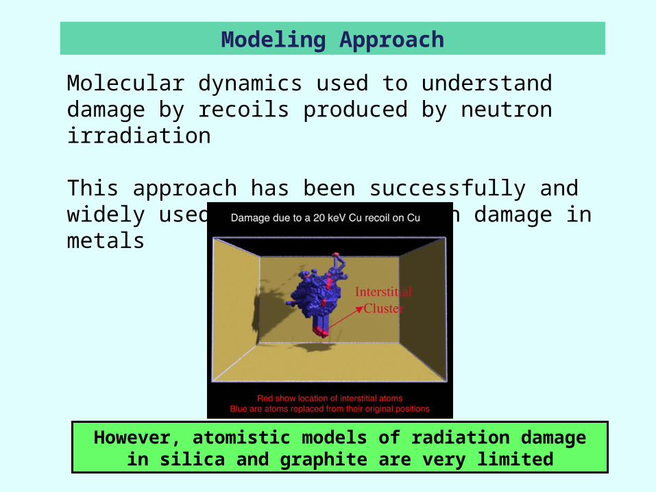
Modeling Approach
Molecular dynamics used to understand damage by recoils produced by neutron irradiation
This approach has been successfully and widely used to study radiation damage in metals
However, atomistic models of radiation damage in silica and graphite are very limited

Neutron irradiation can induce obscuration of the optics through color centers
Spectroscopic observations show increase in defect densities (NBOHC, ODC, E’) with MeV neutron irradiation.
These defect concentrations are shown to decrease with annealing, though the annealing mechanism is not well understood.
There are some suggestions that cascade overlap can also contribute to reduced defect densities
Damage in Silica Glass: issues
Induced optical absorption in silica glasses from neutron and
gamma irradiation
Absorption spectra during annealing at 350°C
C. D. Marshall, J. A. Speth, S. A. Payne, Non-Crystalline Solids, 212 (1997) 59

Introduction to Molecular Dynamics Modeling
Molecular Dynamics for processes far-from-equilibrium, with atomic-scale detail. MD involves the integration of Newton’s Equation,
dxi2/dt2 = -iV(r1,…,rn)
with V(r1,…,rn) taken as modified Born-Mayer-Huggins potentials of Garofalini for Si-O systems,
V2ij = Aij exp(-rij/ij) + ZiZj/rij erfc(rij/ij) + Splined Universal Potential
(For High Energy Interactions)
V3ijk = Si-O-Si and O-Si-O Bond-Angle-Dependent Term
The Garofalini Potentials have been used in numerous studies examining the bulk, surface and interfacial properties of fused silica.
Simulations run with MDCASK LLNL software on a 1024-processor IBM SP2 and a 512-processor Compaq cluster.
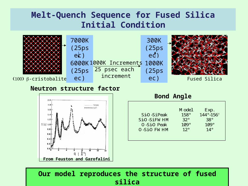
Melt-Quench Sequence for Fused Silica Initial Condition
-cristobalite Fused Silica
6000K(25psec)
7000K(25psec)
300K(25psec)
1000K(25psec)
Model Exp.Si-O-Si Peak 158° 144°-156°
Si-O-Si FWHM 32° 38°O-Si-O Peak 109° 109°
O-Si-O FWHM 12° 14°
1000K Increments25 psec each
increment
Bond AngleNeutron structure factor
From Feuston and Garofalini
Our model reproduces the structure of fused silica
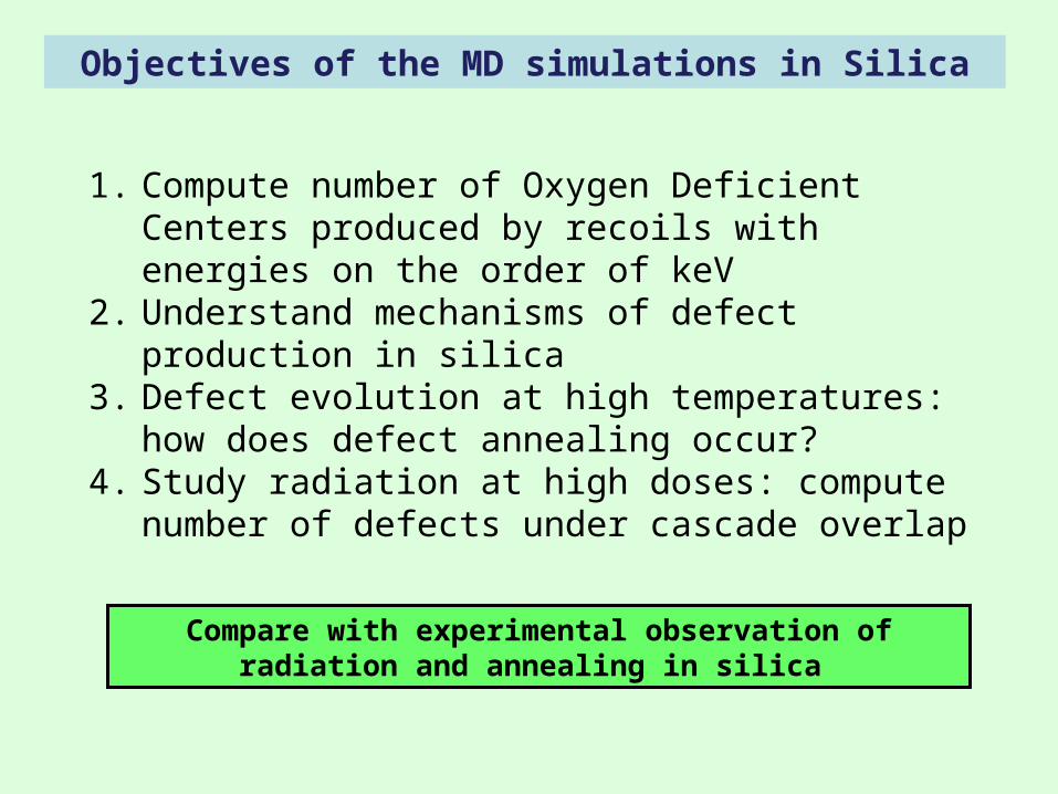
Objectives of the MD simulations in Silica
1. Compute number of Oxygen Deficient Centers produced by recoils with energies on the order of keV
2. Understand mechanisms of defect production in silica3. Defect evolution at high temperatures: how does defect
annealing occur?4. Study radiation at high doses: compute number of defects
under cascade overlap
Compare with experimental observation of radiation and annealing in silica

CascadeOverlap
Annealing(600K)
Undamaged Fused Silica
Damaged Fused Silica
Cascade Simulation
Temperature Bath Cascade Simulation
Is there recovery?
Simulation Procedure
Questions: •What is the mechanism for defect annealing?
•Is there recovery due to cascade overlap?

During the cascade, ODC defects are formed along the cascade
tracks
Many (not all) of the defects are annihilated after the full evolution
of the cascade.
1 keV PKA in Fused Silica
Cascade tracks shown with color corresponding to particle energy. Replacements are those 4-fold coordinated Si whose O neighbors have
changed.
Primary Knock-On Atom
14.3
nm
Replacement
Oxygen Deficient Center
0.08 ps 1.45 ps

2 keV PKA in Fused Silica
Cascade tracks shown with color corresponding to particle energy. Oxygen deficient center (ODC) defects shown as red, while replacements are shown
blue.
Primary Knock-On Atom
14.3
nm
0.06 ps 0.78 ps
TRIM2000 estimates the maximum cascade extent to be ~16nm.
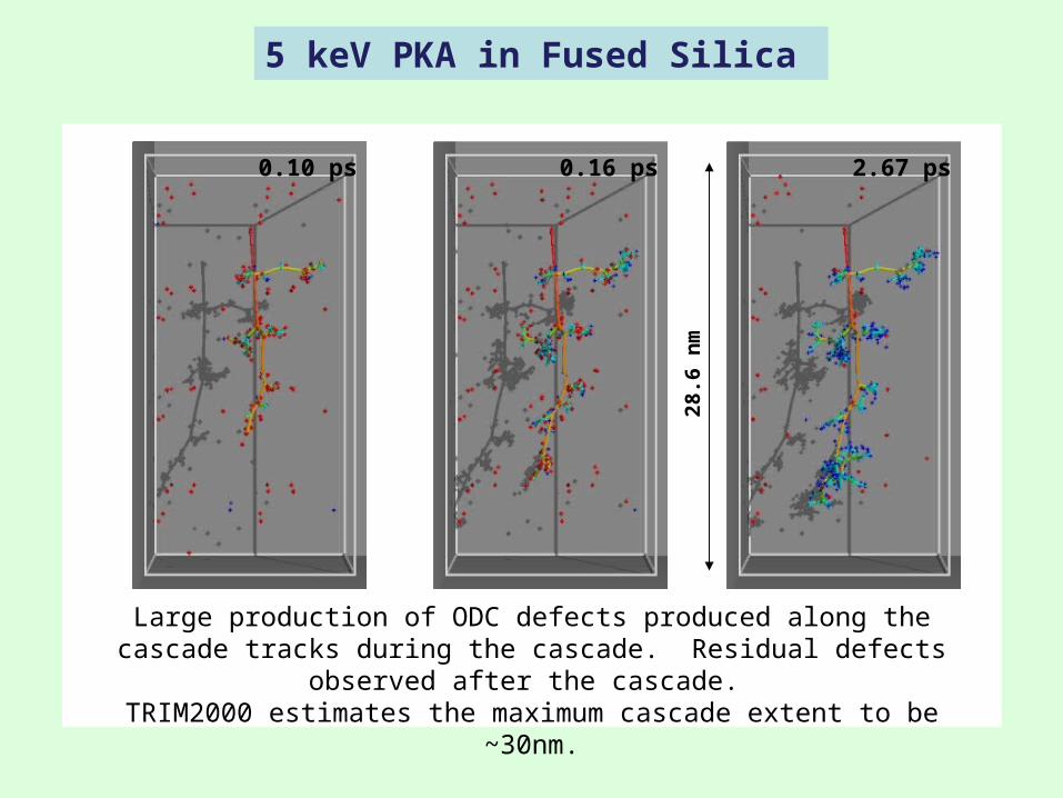
5 keV PKA in Fused Silica
Large production of ODC defects produced along the cascade tracks during the cascade. Residual defects observed after the cascade.
TRIM2000 estimates the maximum cascade extent to be ~30nm.28
.6 n
m
2.67 ps0.10 ps 0.16 ps

Displacements from 5 keV PKA in Fused Silica
2.67 ps 2.67 ps
Displaced atoms are mostly oxygen.
Red segments are Si DisplacementsBlue segments are O Displacements
Displaced atoms are those whose position has moved further than 2Å
from its initial position.
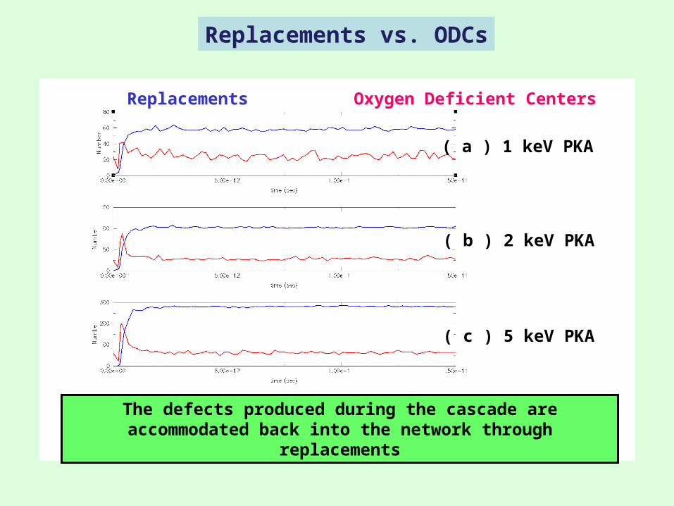
Replacements vs. ODCs
The defects produced during the cascade are accommodated back into the network through replacements
( a ) 1 keV PKA
( b ) 2 keV PKA
( c ) 5 keV PKA
Replacements Oxygen Deficient Centers

Multiple cascades show that the number of defects does not increase linearly with additional overlapped cascades.
Replacements
ODC Defects
Effect of cascade overlap
2nd Cascade
1st Cascade
2 keV PKA in Fused Silica: Damage Overlap
Primary Knock-On Atom
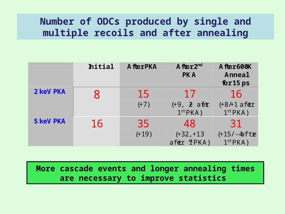
More cascade events and longer annealing times are necessary to improve statistics
Initial After PKA After 2nd
PKAAfter 600K
Annealfor 15 ps
2 keV PKA 8 15(+7)
17(+9, +2 after
1st PKA)
16(+8/+1 after
1st PKA)5 keV PKA 16 35
(+19)48
(+32, +13after 1st PKA)
31(+15/-4 after
1st PKA)
Number of ODCs produced by single and multiple recoils and after annealing

0.07 ps 0.20 ps 1.36 ps
2 keV Recoil in Fused Silica (0.4% OH Content)
ODC
NBOHC
ReplacementCascade Track
2 keV
5 eV
200 eV
20 eV
Structural Defects During the cascade,
ODC and NBO defects are produced along the cascade tracks.
Most of the structural defects recombine and change partners. The remaining residual defects are
precursors to electronic defects.
We are starting to study damage in the presence of OH
Replacements
NBO Defects
2 keV PKA in Fused Silica
ODC Defects
Self-healing properties demonstrated in simulations at very short time scales
Determine the detailed mechanism of self-healing, such as defect transport models, ring contraction models, and viscous flow
models.
Examine the effect of hydrogen (OH, H2O) on defect formation and transport.
Understand the effectiveness of cascade overlap on defect annihilation in fused silica.
Direction of the Model Development for Optics Damage

Defects produced by neutron irradiation can induce:
•Dimensional Changes: swelling
•Changes in Thermal Conductivity
•Production of traps for Tritium
Damage in Carbon materials (Graphite): issues

We are Modeling Radiation Damage in Graphite,Tritium Diffusion and Tritium Retention
Simulation model
Molecular dynamics simulations to study the defects produced during irradiation in graphite
We have implemented a bond-order potential for Carbon-Hydrogen systems in our parallel molecular dynamics code. This is the most accurate empirical potential for Graphite to this date.
Goal of the simulations
Understand defect formation in graphite at the atomistic level and quantify number of defects with energy of recoils
Understand Tritium diffusion in the presence of defects generated during irradiation
Combine results of defect production with detailed neutron flux calculations at the first wall and understand the effects of pulse irradiation in final
microstructure

Interatomic potentialBrenner’s Reactive Bond-Order Formalism
Multibody Bond-Order Potential to model C/H and C/H/O systems.
Stabilizes sp2 and sp3 carbon based on local bonding environment.
Used in studies of particle impacts with graphite (Beardmore and Smith, 1995) and polymers (Smith, 1996)
O(n) scalable, comparable to Tersoff potential in complexity
Parallel code for Bond-Order potentials implemented at LLNL (ASCI Blue, TC2K)
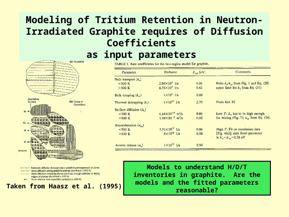
Modeling of Tritium Retention in Neutron-Irradiated Graphite requires of Diffusion Coefficients
as input parameters
Taken from Haasz et al. (1995)
Models to understand H/D/T inventories in graphite. Are the models and the fitted
parameters reasonable?

Atomistic Modeling Provides Details into the Formationand Behavior of Defects Produced during
Neutron Irradiation
Damage produced by a 200 eV C recoil along the c-direction in graphite
Vacant sites
Interstitials
Radiation produces vacant sites in the lattice that could act as trapping sites for Tritium
Calculations of defect structures and energetics will have to be validated with first principles calculations and compared to previous models
Our calculations show a strong binding between a single vacancy and H ~ 3.8 eV

MD simulations show that amorphization of SiC requires of the formation of antisitesAmorphization is heterogeneous
SiC
Radiation induced amorphization in SiCA. Romano, S. Yip and Ju Li (MIT) and M. J. Caturla and B. D. Wirth (LLNL)
12.50 % Si FPs 25 % Si FPs
12.5 % Si FPs 25 % Si FPsNo antisites
50% antisites (W.J. Weber, Nucl. Inst. Meth. Phys. B166-167 (2000),98)
0.0
0.2
0.4
0.6
0.8
1.0
50% Antisites
Defected Fraction, f
d
Fraction of Si Interstitials0.00 0.05 0.10 0.15 0.20 0.25
1 - exp[-k(x/Φ)m]
NoAntisites
Direction of the Model Development for Damage in Graphite
We have developed the computational capability to study radiation damage in C/H systems at the atomistic level with large scale MD
simulations
Compute number of defects produced in graphite during irradiation with energies of ~ keV
Study the atomistic mechanisms for Tritium diffusion in graphite
Study the binding of Tritium to different Vacancy complexes produced during irradiation
The computed activation energies are input parameters for continuum models for defect diffusion
The work was performed under the auspices of the U.S. Department of Energy by University of California Lawrence Livermore National
Laboratory under contract No. W-7405-Eng-48