atomistic mechanisms of metal-assisted hydrogen storage in
TRANSCRIPT

OAK RIDGE NATIONAL LABORATORYU. S. DEPARTMENT OF ENERGY
Atomistic Mechanisms of Metal-Assisted Hydrogen Storage in Nanostructured Carbons
Nidia C. Gallego*, Cristian Contescu, Fred Baker, Xianxian Wu 1Chong-L. Fu, James Morris, Rachel Aga 1Steve Pennycook, Klaus van Benthem 1
Dan D. Edie, Halil Tekinalp 2
1 Materials Science and Technology DivisionOak Ridge National Laboratory, Oak Ridge, TN 37831-6087, USA
2Center for Advanced Engineering Fibers and FilmsClemson University, Clemson, SC 29634-0909, USA
DOE Hydrogen Program - Annual Merit Review MeetingArlington, VA – May 19, 2006

OAK RIDGE NATIONAL LABORATORYU. S. DEPARTMENT OF ENERGY
Collaborative Project between ORNL and Clemson University
• Project Starting Date: August 2005
• Funding: $450k/yr− One-time supplement $117k

OAK RIDGE NATIONAL LABORATORYU. S. DEPARTMENT OF ENERGY
The thrust of this project is the development of a broader science foundation for identification of
the atomistic mechanisms of metal-assisted hydrogen storage in nanostructured carbons.
To help answer the question: “do carbon materials or modified carbon materials have
potential for hydrogen storage?”

OAK RIDGE NATIONAL LABORATORYU. S. DEPARTMENT OF ENERGY
Hydrogen Storage Capacities of Carbon MaterialsHydrogen Storage Data Literature Reference
H2 Uptake(wt%)
Temperature(K)
Pressure(MPa)
1st Authorof Paper
PublicationYear
GNF (herringbone) 68 294 11.4 Chambers 1998
GNF (platelet) 54 294 11.4 Chambers 1998
K-MWNT ~ 1.8 < 313 0.1 Yang 2000
Li-MWNT 20 ~ 473-673 0.1 Chen 1999
K-MWNT 14 < 313 0.1 Chen 1999
GNF (tubular) 11 294 11.4 Chambers 1998
CNF ~ 10 294 10.1 Fan 1999
GNF ~ 10 294 8-12 Gupta 2000
SWNT (high purity) 8.3 80 7.2 Ye 1999
SWNT (low purity) 5-10 294 0.04 Dillon 1997
CNF ~ 5 294 10.1 Cheng 2000
SWNT (50% purity) 4.2 294 10.1 Liu 1999
MWNT < 1 294 e-chem Beguin 2000
SWNT ~ 0.1 300-520 0.1 Hirscher 2000
Various < 0.1 294 3.5 Tibbets 2001
Activated Carbon ~ 1 294 12 Baker (1995)
CarbonMaterial

OAK RIDGE NATIONAL LABORATORYU. S. DEPARTMENT OF ENERGY
Carbon-only Systems: Low Storage Capacity at Room Temperature
• Physisorption of H2 in activated carbons− Very low at room temperature− Increases greatly at cryogenic temperatures− Scales with surface area
0.00
0.05
0.10
0.15
0.20
0.25
0.30
0.35
0 500 1000 1500 2000 2500BET Surface Area [m2/g]
H2
Upt
ake
at 2
0 ba
r, 29
4 K
[w
t%]
As-produced CNT
Anshan Fibers
Purified CNT
CMT Monolith SMM-19
Wood-based carbon
CMT Monolith SMS-48
Coal-based carbon
Hydrogen Adsorption Isotherms at Room Temperature
0.0
0.1
0.2
0.3
0.4
0 50 100 150 200 250 300
Pressure [psi]
Wei
ght G
ain
[%]
Wood-derived carbon
Coal-derived carbon
Hydrogen Adsorption Isotherma at RT
0.00
0.03
0.06
0.09
0.12
0.15
0.18
0 100 200 300
Pressure [psi]
Wei
ght G
ain
[%]
As-produced NTPurified NT
Carbon nanotubes
• Physisorption on carbon nanotubes− Capacity is not greater, both on as-produced
and purified NT− Isotherms are of different type
Gallego (ORNL) unpublished results (2002-2003)
Wood based Carbon at 77 K
0123456
0 50 100 150 200Pressure [bar]
Mas
s up
take
[%]
AdsorptionDesorption
but higher at cryogenic temp.

OAK RIDGE NATIONAL LABORATORYU. S. DEPARTMENT OF ENERGY
Hydrogen Storage Enhancement by Added Metals
Hydrogen Storage Data Literature Reference
H2 Uptake(wt%)
Temperature(K)
Pressure(MPa)
1st Authorof Paper
PublicationYear
Pt / ACF < 0.1 300 0.1 Ozaki 2000
~ 60 % Ti/SWNT 1.5 300 0.1 Hirscher 2001
20 % Ni (Co) / carbon 2.8 773 3-5 Zhong 2002
NiMgO / MWNT 3.6 300 6.9 Lueking 2003
Fe, Ni, Co / GNF 6.5 300 12 Browning 2002
Pd / ACF; Pd / ACF 0.3 303 3 Takagi 2004
Pd / CNT 1.5 573 0.1 Yoo 2004
2.5 % Pd / CNT 0.66 300 2 Zacharia 2005
1.5 % V / CNT 0.69 300 2 Zacharia 2005
6 % Ni / MWNT 2.8 300 4 Kim 2005
25 % Ni, 1.5 % Y / SWNT 0.1 300 6 Costa 2005
15 % Ni, 2 % Y / SWNT 3 77 0.04 Callejas 2004
Carbon Materialand Metal Content

OAK RIDGE NATIONAL LABORATORYU. S. DEPARTMENT OF ENERGY
Carbon as a catalyst support
Carbon alone
1 % Pt / carbon
Expected, if all Pt on surface
350 oC; 600 Torr H2
• 1960s: GE pioneers PEM fuel cells using Pt/carbon black electrocatalyst
• 1964: Robell, Ballou and Boudart attempted to measure Pt dispersion by chemisorption of H2.
• Much more H2 was adsorbed than expected, if all Pt atoms were surface atoms.
Fast adsorption, dissociativeSlow (activated) surface diffusion
Robell, Balou, Boudart, J. Phys. Chem. (1964)Burstein, Lewin, Petrow, Physik Z. (1933)
• H2 spillover = dissociation + slow surface diffusion + remote storage

OAK RIDGE NATIONAL LABORATORYU. S. DEPARTMENT OF ENERGY
The Rationale of Our Approach
In catalytic systems, spillover works like a H-pump• H2 dissociates into H atoms on metal particles (Group VIII catalyst)• H atoms are consumed in reactions with another reagent (hydrogenation etc)
In hydrogen storage systems, the H-pump needs a stable “well” for storage of H atoms:
• H2 dissociates into H atoms on Group VIII catalyst• H atoms must find stable positions for storage on carbon nanostructures
The optimal system for H storage must have the catalyst sites (metal particles) and the “well” (defective carbon
nanostructure) in a close spatial relationship.

OAK RIDGE NATIONAL LABORATORYU. S. DEPARTMENT OF ENERGY
Basic Assumptions
The enhancement of H2 storage in metal-doped nanostructured carbons results from synergetic combination of two factors:
• Hydrogen spillover − metal as a catalyst
• Availability of appropriate carbon nanostructures− metal as a structure former

OAK RIDGE NATIONAL LABORATORYU. S. DEPARTMENT OF ENERGY
Tasks• Theory & Simulation
− First-principles calculations of H2 and H interaction with graphene sheets− Grand Canonical Monte Carlo (GCMC simulations) of hydrogen absorption/desorption − (POSTER Presentation)
• Synthesis of Pd-Doped Activated Carbon Fiber (ACF) from an Isotropic Pitch Precursor− Role of pitch chemistry in stabilization and dispersion of metal nanoparticles− Effect of metal precursors on stabilization and dispersion of metal nanoparticles in pitch− Effect of heat treatment conditions on dispersion of metal particles− Metal selection
• Materials Characterization− Metal nanoparticles: formation and properties− Nanostructure of carbon in the neighborhood of metal particles− Surface and pore size distributions measurements− Hydrogen storage measurements− Identification of hydrogen-containing entities
OAK RIDGE NATIONAL LABORATORYU. S. DEPARTMENT OF ENERGY
Development of Metal-Containing Activated Carbon Fibers

OAK RIDGE NATIONAL LABORATORYU. S. DEPARTMENT OF ENERGY
Characterization / Application
Activation
Activated carbon fibers
Oxidation / Stabilization
Carbonization
Mixing
Melt-spinning
Isotropic pitch
Metal salt

OAK RIDGE NATIONAL LABORATORYU. S. DEPARTMENT OF ENERGY
STEM Characterization of Pd-containing ACF
30 nm
100 nm
100 nm
Z-contrast images
EDS

OAK RIDGE NATIONAL LABORATORYU. S. DEPARTMENT OF ENERGY
TS
G
G
G
G
High Resolution STEM of Carbon Nanostructure Around a ~ 5 nm Size Pd Particle
5 nm
Pd
Pd particleSmall domains of parallel (but disordered) graphene layers Larger domains of turbostratic carbon

OAK RIDGE NATIONAL LABORATORYU. S. DEPARTMENT OF ENERGY
Understanding the development of Pd particles throughout the ACF production
processPitch selection and mixing
Heat treating
Control dispersion and particle size of metal particles in the ACF

OAK RIDGE NATIONAL LABORATORYU. S. DEPARTMENT OF ENERGY
Oligomeric Pitches From Petroleum by-Products
Dickinson, 1985
MW=920Mesogen
MW=380
Crude Oil
Gas, Distillates
Vacuum Residua
Fluid Catalytic Cracking
Heavy Gas Oil Fraction
Lights
Heat-Soaking
Heavy OilsFCC Decant
Oil
Isotropic Pitch
0.000
0.001
0.002
0.003
0.004
0.005
250 500 750 1000 1250MW
Nor
mal
ized
Inte
nsity Monomer
Dimer
TrimerTetramer

OAK RIDGE NATIONAL LABORATORYU. S. DEPARTMENT OF ENERGY
Goal: Maximize the dispersion of metal-containing particles by tailoring the molecular composition of the precursor pitch.
ΔT
Extruder and Metering Pump
A Power Supply
Packed Section of Column
Level Detector
Solvent Pump
T
T
T
T
T
TPre-heater
Regulating ValveP
Overhead Product
Bottom Product
Reflux Finger
Control of Precursor Pitch by Dense Gas Extraction

OAK RIDGE NATIONAL LABORATORYU. S. DEPARTMENT OF ENERGY
Extraction of Commercial Pitches
• Commercially available A-240 and M-50 pitch are being evaluated• Different operating conditions yield different bottom products • Significant quantities of bottom product are attainable
0.000
0.001
0.002
0.003
0.004
250 500 750 1000 1250m/z, Daltons
Nor
mal
ized
Inte
nsity
FeedIsothermalThermal Gradient
SampleBottom
Flowrate(g/hr)
Softening Point (oC)
Feed - 88Isothermal 27 278Gradient 6 360

OAK RIDGE NATIONAL LABORATORYU. S. DEPARTMENT OF ENERGY
On-going work at Clemson includes:
• Fractionation of pitch in order to optimize spinnabilityand chemical interactions with metals
• Characterization of molecular structure and composition of optimum pitch fraction
• Study the effect of mixing parameters and metal precursor on particle dispersion
• Optimize heat treatment conditions in order to minimize metal particle sintering

OAK RIDGE NATIONAL LABORATORYU. S. DEPARTMENT OF ENERGY
Transformation during Heat Treatment
Particle size (nm):
44 (Pd)
4 (PdO)0
200
400
600
800
1000
1200
10 20 30 40 50 60 70 802θo
CPS
Carbonized
Stabilized
Pd (111)
Pd (200)
Pd (220)
PdO (101)
260oC
1000oC

OAK RIDGE NATIONAL LABORATORYU. S. DEPARTMENT OF ENERGY
Transformation during carbonization (in-situ XRD)
25oC
175oC
275oC375oC
875oC975oC
75oC
825oC775oC
675oC575oC
475oC
25oC
PdO
Pd

OAK RIDGE NATIONAL LABORATORYU. S. DEPARTMENT OF ENERGY
Transformation during carbonization (in-situ XRD) Observations:
PdO peak disappeared after ~ 275oC
Above 675oC, a small shoulder which should be Pd (111) peak appeared. This peak grows with increasing temperature.
The strongest Pd peaks was seen in the pattern of the sample after cooling down to 25oC.

OAK RIDGE NATIONAL LABORATORYU. S. DEPARTMENT OF ENERGY
Understanding Particle Growth During Carbonization and Activation
Oxidized fiber
30 nm
800 ºC, Ar
30 nm
1000 ºC, Ar
30 nm
Activated, 900 ºC, CO2
30 nm
0
0.02
0.04
0.06
0.08
0.1
0 200 400 600 800
Temperature (oC)
Der
iv. W
eigh
t (%
/o C)
K-230, in ArK-230, in CO2K-230-Pd, in ArK-230-Pd, in CO2
PdOPd
Carbonization
Activation in CO2
60
70
80
90
100
0 200 400 600 800
Temperature (oC)
Wei
ght L
oss
(%)
K-230, in ArK-230, in CO2K-230-Pd, in ArK-230-Pd, in CO2
250 ºC, Ar
30 nm

OAK RIDGE NATIONAL LABORATORYU. S. DEPARTMENT OF ENERGY
0% BO
20% BO
47% BO
62% BO
73% BO
Crystallite size (nm) of Pd
calculated from (111) peaks:
0% 4720% 7047% 6262% 9673% 69
During Activation:• Pd crystallite size increases• Graphite 002 peak decreases

OAK RIDGE NATIONAL LABORATORYU. S. DEPARTMENT OF ENERGY
Pd-containing fiber before activation (0% BO)
Pd-containing fiber after CO2 activation (20% BO)
Carbon Structures Revealed by HREM

OAK RIDGE NATIONAL LABORATORYU. S. DEPARTMENT OF ENERGY
Observations
Presence of Pd during carbonization affects the atomic and electronic structure of carbon.After the stabilization step, Pd was well dispersed in carbon by current preparation procedures.The conversion of PdO to Pd in inert gas occurred at temperatures > 200oC.The sintering of Pd nanoparticles was observed during both carbonization and activation steps.

OAK RIDGE NATIONAL LABORATORYU. S. DEPARTMENT OF ENERGY
On-going work
• Optimization of heat treating process in order to control particle sintering and preserve high dispersion− one-step carbonization/activation
• Understanding the effect of metal particles on local carbon structure and electronic properties − Continue work with in-situ x-ray analysis− High resolution STEM and EELS analysis using aberration
corrected microscope (POSTER)

OAK RIDGE NATIONAL LABORATORYU. S. DEPARTMENT OF ENERGY
Hydrogen Uptake on Metal-Containing Activated Carbon Fibers

OAK RIDGE NATIONAL LABORATORYU. S. DEPARTMENT OF ENERGY
Gravimetric Adsorption Instrument
• 200 & 1000 mg sample capacity• Balance resolution of 1 μg • Up to 20 bar pressure below 500ºC• 1 bar pressure at 1000ºC• On-line mass spectrometer
IGA System (Hiden Analytical)
Procedure
• Sample size ~ 100 mg• Outgas to 10-6 mbar at 300ºC• Measure He density (buoyancy)• Slow pressurizing rate• Long equilibrium time• In-line MS monitoring

OAK RIDGE NATIONAL LABORATORYU. S. DEPARTMENT OF ENERGY
Hydrogen isotherm (at 30oC) of Pd sponge shows hydride formation and hysteresis at low pressure
0
0.2
0.4
0.6
0.8
0 0.2 0.4 0.6 0.8 1
Pressure (MPa)
Mas
s up
take
(%
)
Blue = adsorptionRed = desorption
0.66 % H → PdH0.706
0
0.2
0.4
0.6
0.8
0 0.005 0.01
OAK RIDGE NATIONAL LABORATORYU. S. DEPARTMENT OF ENERGY
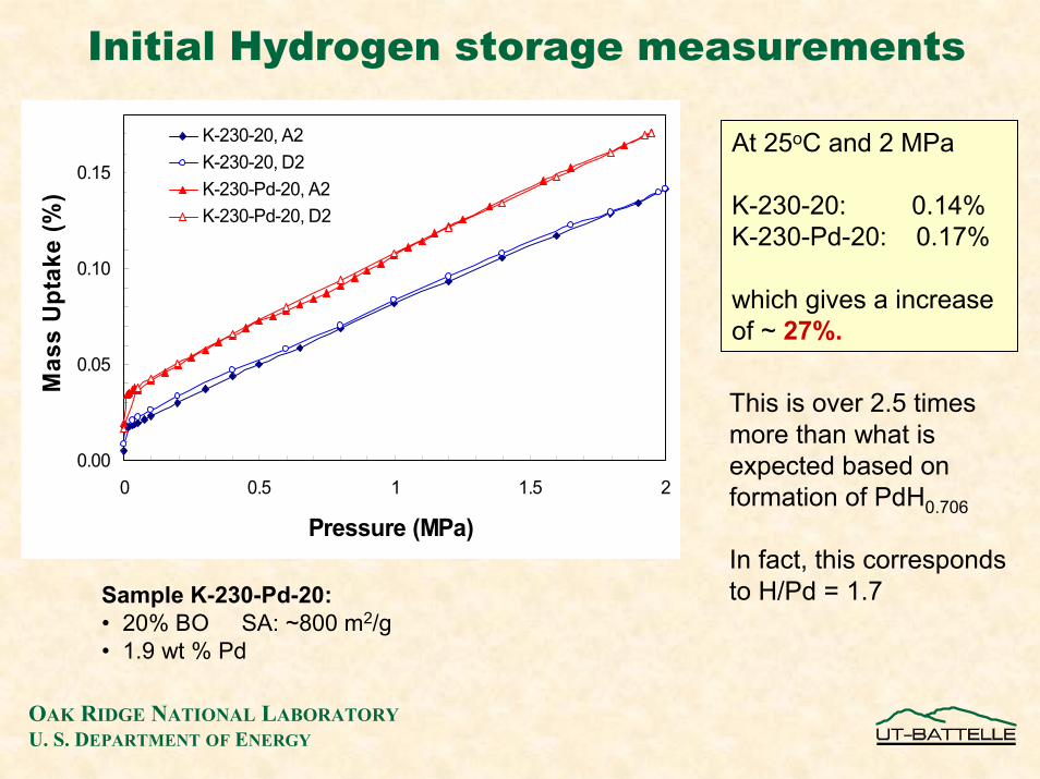
Initial Hydrogen storage measurements
At 25oC and 2 MPa
K-230-20: 0.14%K-230-Pd-20: 0.17%
which gives a increase of ~ 27%.
0.00
0.05
0.10
0.15
0 0.5 1 1.5 2
Pressure (MPa)
Mas
s U
ptak
e (%
)
K-230-20, A2K-230-20, D2K-230-Pd-20, A2K-230-Pd-20, D2
This is over 2.5 times more than what is expected based on formation of PdH0.706
In fact, this corresponds to H/Pd = 1.7Sample K-230-Pd-20:
• 20% BO SA: ~800 m2/g• 1.9 wt % Pd

OAK RIDGE NATIONAL LABORATORYU. S. DEPARTMENT OF ENERGY
Pd peak after exposure to H2 (shows reversal of hydride peak to Pd)
Pd peak under vacuum
Pd peak under H2 (1 bar) (shows hydride formation)
Hydride Formation at 1 bar H2 Pressure
In-situ High-Pressure X-ray Diffraction Studies

OAK RIDGE NATIONAL LABORATORYU. S. DEPARTMENT OF ENERGY
• Use Anton PAAR stage for high pressure (10 bar) in-situ XRD measurements under H2 loading at RT
• Monitor changes on carbon 002 peak caused by exposure to high pressure H2− Do expansions of carbon lattice occur ?− Do irreversible changes in carbon structures occur on cycling ?
• Identify changes in Pd phase and particle size with increasing H2pressure − Correlate with high pressure H2 adsorption / desorption results
On-going Work

OAK RIDGE NATIONAL LABORATORYU. S. DEPARTMENT OF ENERGY
Summary• Conditions for mixing Pd salt in the pitch precursor were found, which
ensure good dispersion of PdO in spun and stabilized fibers
• Using TGA, STEM, and in-situ high temperature XRD, the effect of heat treatment conditions on dispersion and phase composition of Pd was understood
• A strategy was designed for limiting the sintering of Pd by combining carbonization and activation in a single step
• Aberration-corrected HR-STEM and EELS spectra are being used to characterize local atomic and electronic structures on carbon atoms in Pd-ACF. It was found that presence of Pd during carbonization affects local structures on carbon atoms.
• Using in-situ controlled atmosphere XRD it was shown that Pd hydride is reversibly formed on contact with H2, and the degree of transformation is pressure-dependent.
• H2 sorption was monitored gravimetrically (RT, 20 bar) in well controlled conditions. Presence of Pd (1.9 %) induces a 27% enhancement of adsorption, corresponding to H/Pd = 1.7. This is an indirect proof of H2 spillover on Pd-ACF (even at 20 % b/o).

OAK RIDGE NATIONAL LABORATORYU. S. DEPARTMENT OF ENERGY
Future Work• Identify pitch fractions with uniform chemical composition and good spinnability
and use for controlled synthesis of Pd-doped fibers• With Dan Edie – Clemson Univ.
• Confirm spillover mechanism− Demonstrate enhanced adsorption in physical mixtures containing a H atom source
(Pd-ACF) and a H receptor (ACF) • with Ralph Yang – Univ. Missouri
− Direct evidence from neutron scattering studies • with Danny Neumann - NIST
− Identify the role of “chemical bridges” at Pd-carbon interface • HRTEM
• Confirm the role of Pd as a defect former in carbon structure− Sub-Angstrom resolution STEM in combination with EELS and in-depth analysis of
XRD and neutron diffraction data• Confirm dynamic effects of H2 on carbon structures
− In-situ high pressure XRD − Neutron scattering
• Use accurate H2 adsorption measurements at cryogenic temperatures and < 1 bar to characterize micropores accessed by H2 , and predict H2 adsorption at high pressures and temperatures based on DFT models
• with Jacek Jagiello – Quantachrome

OAK RIDGE NATIONAL LABORATORYU. S. DEPARTMENT OF ENERGY
Acknowledgments
• This work was sponsored by a grant from Office of Basic Energy Sciences, Division of Materials Science and Engineering, U.S. Department of Energy under contract No. DE-AC05-00OR22725 with UT-Battelle, LLC
• Oak Ridge National Laboratory is managed for Department of Energy by U.T. Battelle