atmospheric compensation and tracking using active ... · • higgs, barclay, murphy, and...
TRANSCRIPT

• HIGGS, BARCLAY, MURPHY, AND PRIMMERMANAtmospheric Compensation and Tracking Using Active Illumination
VOLUME 11, NUMBER 1, 1998 LINCOLN LABORATORY JOURNAL 5
Atmospheric Compensationand Tracking UsingActive IlluminationCharles Higgs, Herbert T. Barclay, Daniel V. Murphy, and Charles A. Primmerman
■ The U.S. Air Force is developing the airborne laser (ABL), whose mission isto engage and destroy theater ballistic missiles such as the SCUD while thesemissiles are in their boost phase. This mission capability requires high-energylaser propagation over long horizontal paths (200 to 300 km) through the upperatmosphere. To be effective in the presence of atmospheric turbulence, the ABLmust utilize precision tracking and adaptive-optics compensation. Although thestrength of atmospheric turbulence at ABL altitudes (35,000 to 45,000 feet) isrelatively weak compared to sea level, the long horizontal laser-propagationpaths create severe challenges for the adaptive-optics and tracking systems. Anequally difficult challenge is created because the missile provides no beacon forthe adaptive-optics and tracking systems. The target missile must be activelyilluminated so that backscatter from the missile body can be used to form animage for the tracking system and provide a beacon for the adaptive-opticssystem. To understand this problem better and to improve system performance,we conducted propagation experiments at the Firepond telescope facility onMillstone Hill in Westford, Massachusetts. These tests utilized a 5.4-kmhorizontal propagation range between Millstone Hill and a fire tower in thetown of Groton, Massachusetts. These experiments, which demonstrated for thefirst time active tracking and adaptive compensation under ABL conditions,suggest that the ABL can meet its mission goals and perform at levels requiredfor effective theater missile defense.
T .. the airbornelaser (ABL) as a weapon system to engage anddestroy multiple ballistic missiles at ranges as
distant as several hundred kilometers. Current de-signs for the ABL envisage a Boeing 747 aircraftequipped with a 1.5-m nose-mounted beam director.The laser weapon will be a multimegawatt chemicaloxygen-iodine laser operating at a wavelength of 1.3microns. High-bandwidth adaptive-optics and track-ing systems are required to correct for the beam jitterand higher-order phasefront aberration caused by tur-bulence in the atmosphere.
Because the missile being targeted provides nobeacon (i.e., the missile is not cooperative) for theABL adaptive-optics and tracking systems, the missilemust be actively illuminated. This illumination is ac-complished by using two separate illuminator lasersystems. A track illuminator illuminates the nose-tipregion of the missile, as shown in Figure 1. Backscat-ter from the track illuminator is collected and used asinput to a high-bandwidth imaging tracker, and im-aging-tracker output is used to correct the high-fre-quency tilt jitter induced by atmospheric turbulence.
An adaptive-optics illuminator illuminates a re-

• HIGGS, BARCLAY, MURPHY, AND PRIMMERMANAtmospheric Compensation and Tracking Using Active Illumination
6 LINCOLN LABORATORY JOURNAL VOLUME 11, NUMBER 1, 1998
lation (i.e., temporal and spatial intensity fluctuationscaused by turbulence-induced phasefront variations)of both the image of the boosting missile target thatmust be tracked and the high-energy laser that mustengage it.
Making the ABL an effective weapon system re-quires technology advances in many areas. Some ofthe most challenging areas are aircraft payload design,high-energy laser technology, optical sensor develop-ment, and atmospheric compensation and tracking.This article concerns laser-propagation experimentsand field studies we conducted at the Firepond tele-scope facility on Millstone Hill in Westford, Massa-chusetts. The purpose of these experiments was tobetter understand the problem of atmospheric com-pensation and tracking and to determine ways of im-proving ABL system performance.
Firepond experiments began in 1992 and werecompleted in 1997. The initial experiments were de-signed to investigate the limitations of basic atmo-
FIGURE 1. Airborne laser (ABL) illuminator geometry for active compensation and tracking of a boost-phase missilethrough atmospheric turbulence. The track illuminator (shown in blue) illuminates the nose-tip region of the missile toprovide backscatter for the tracker. The adaptive-optics illuminator (shown in green) illuminates a region farther back onthe missile body to provide a beacon for the adaptive-optics system. The high-energy laser (shown in red) is directedalong the same path as the adaptive-optics illuminator return, but because of missile motion the laser strikes the missileat a point displaced by a distance 2Lv/c, where v is the missile’s velocity, L is its range, and c is the speed of light. Thelikely platform for the ABL will be a modified Boeing 747 aircraft, equipped with a 1.5-m nose-mounted beam transmitterand a multimegawatt laser operating at a 1.3-µm wavelength. The ABL can engage targets at altitudes between cloud top(approximately 15 km) and booster burnout (approximately 60 km).
gion farther back on the missile body to provide abeacon for the adaptive-optics system. Output fromthe adaptive-optics system is used to compensate thehigher-order aberrations induced by atmospheric tur-bulence. The high-energy laser is directed along thesame path as the adaptive-optics illuminator return; itstrikes the missile at a point displaced by a distance2Lv/c, where v is the missile’s velocity, L is its range,and c is the speed of light. This distance 2Lv/c is howfar the missile moves during the time it takes for theilluminator return to reach the ABL and then for thehigh-energy laser beam to reach the missile.
In the familiar ground-to-space scenarios [1] inwhich adaptive optics works well, atmospheric turbu-lence is strong near the ground and weakens rapidlywith increasing altitude. The ABL mission, however,requires missile tracking and laser propagation acrosslong horizontal ranges over which atmospheric turbu-lence is weak but relatively constant. This type of la-ser-propagation path leads to severe intensity scintil-
Separate illuminator lasers fortracking and adaptive optics
12 km
15–60 km
100-to-400-km propagation range
High-energy laser
Ground
2Lv/c

• HIGGS, BARCLAY, MURPHY, AND PRIMMERMANAtmospheric Compensation and Tracking Using Active Illumination
VOLUME 11, NUMBER 1, 1998 LINCOLN LABORATORY JOURNAL 7
spheric compensation and tracking in the presence ofsevere scintillation [2]. These tests utilized a coopera-tive beacon that was produced by placing a laser-gen-erated point source at the target. Results from thesetests were important because they demonstrated thatadaptive-optics compensation could be effective evenfor the challenging propagation scenarios expectedfor ABL. Beginning in 1995 the Firepond facility wasreconfigured to include the more difficult problem ofactive illumination of the target, including illumina-tion with multiple beams (see the sidebar entitled“Multibeam Illumination”). Initially, the experimentsdealt only with active-tracking concerns [3]; thehigher-order atmospheric compensation was per-formed by using point-source beacons. Results fromthese tests confirmed the benefits of multibeam illu-mination for active tracking. The most recent experi-ments included active illumination for both thetracking and the adaptive-optics systems [4]. The ex-perimental configuration used for these tests con-formed closely to the ABL contractor’s concept for at-mospheric compensation and tracking.
Parameter Scaling
Although the Firepond experiments were conductedon a ground-level laser-propagation path, the resultsare applicable to the ABL program because the ex-periment was scaled in such a way that the turbulenceeffects on the Firepond laser beam near the groundwere the same as would be expected on the ABL beamat high altitude. One requirement for effective scalingis that the distribution of turbulence strength alongthe path should be the same at Firepond as it is for theABL. For many ABL engagement scenarios, the targetis engaged at altitudes much greater than the altitudeof the ABL, in which case turbulence is weaker nearthe target than at the aircraft. For those cases, only ap-proximate scaling can be achieved at Firepond, wherethe turbulence strength is expected to be fairly con-stant along the entire path. For some ABL scenarios,however, the target is engaged at low altitude, wherethe turbulence strength is expected to be nearly uni-form along the entire path. These scenarios, whichhave the highest scintillation and tend to be the moststressing for the adaptive optics, can be well matchedby the Firepond experiments. For nearly horizontal
engagement scenarios, proper scaling of the Firepondexperiments can be ensured by preserving four di-mensionless parameters [5]: turbulence strength, nor-malized isoplanatic angle, Fresnel number, and scin-tillation strength (Rytov variance).
The turbulence strength, D/r0 , is the ratio of trans-mitter diameter to atmospheric coherence length. Forthe particular ABL scenario under study at Firepondthe value of D/r0 is expected to range between 2 and6. The normalized isoplanatic angle, θ0/[λ/D], is theratio of isoplanatic angle to diffraction-limited angu-lar resolution. Qualitatively, the isoplanatic angle canbe thought of as the angular field of view over whichhigh-fidelity imaging is possible. For the ABL sce-nario its value will range between 1.2 at weak levels ofturbulence levels to 0.5 at higher levels of turbulence.It is unusual in adaptive-optics applications for thisvalue to be less than unity, since such a low valuemeans that even the system’s diffraction-limited reso-lution is larger than the maximum angle over whichgood imaging can be achieved. The Fresnel number,D2/λL, is the square of the transmitter diameter di-vided by the product of wavelength and propagationrange, and is an indicator of the importance of dif-fraction (the transformation of phasefront variationsinto intensity variations as the beam propagates). Forthe ABL scenario its value will range between 4 and14. Finally, the scintillation strength, or Rytov vari-ance, σR
2, is a measure of the severity of intensityscintillation caused by the distributed atmosphericturbulence. For the ABL scenario its value will rangebetween 0.1 and 0.5.
Note that the atmospheric coherence length r0,the isoplanatic angle θ0, and the scintillation strength
Table 1. Propagation Parameters forthe Firepond Facility and a Representative
Airborne Laser Scenario
Firepond ABL
Transmitter diameter D 15 cm 1.5 m
Laser wavelength λ 0.5 µm 1.3 µm
Propagation range L 5.4 km 220 km

• HIGGS, BARCLAY, MURPHY, AND PRIMMERMANAtmospheric Compensation and Tracking Using Active Illumination
8 LINCOLN LABORATORY JOURNAL VOLUME 11, NUMBER 1, 1998
M U L T I B E A M I L L U M I N A T I O N
of theatmospheric turbulence expectedfor airborne laser (ABL) engage-ment scenarios is relatively weakbecause of the expected high alti-tude of these encounters, the tur-bulence is uniformly distributedalong the entire propagation path.One result of this distributed tur-bulence is strong intensity scintil-lation, which produces nonuni-form illumination of the target.This nonuniform illuminationhas severe impact on the perfor-mance of an imaging tracker.
The multibeam illuminationapproach can reduce the intensityscintillation and improve trackerperformance by propagating notone but many separate illumina-tor beams. As indicated in FigureA, the illuminator laser is dividedinto multiple beams, each ofwhich is launched from a separateregion of the transmitter. In prac-tice, this division might be accom-plished by using a single laser withspecially designed optics and de-lay lines, or by using individuallasers. In the example shown here,four beams are produced from asingle laser. In either case, eachbeam must be incoherent withrespect to all the others. As thebeams propagate toward the tar-get, each beam samples a slightlydifferent atmospheric path and, asa result, each produces a differenttarget-plane irradiance profile.
When these individual profiles areoverlapped on target, they add in-coherently to produce a more uni-form irradiance profile.
The Firepond active-trackingtests reported here were per-
formed by using a multibeam illu-minator designed by Lockheed-Martin Missiles & Space, a mem-ber of the ABL contractor team.The design of the Lockheed illu-minator permits the power from a
FIGURE A. Multibeam illuminator. In our approach to multibeam illumination,output from a laser is divided into multiple mutually incoherent beams. Eachbeam (four beams are shown in this example) is propagated from a separateregion of the beam transmitter, but all beams are made to overlap on target.
Optics Laser
(a) (b) (c)
FIGURE B. Transmitter-beam configuration for multibeam-illuminator tests.These three diagrams show the multibeam footprint on the Firepond telescopeprimary mirror. Open-loop and closed-loop track data were recorded by using(a) one, (b) four, and (c) nine illuminators as shown. The total transmittedpower was held constant for all tests.

• HIGGS, BARCLAY, MURPHY, AND PRIMMERMANAtmospheric Compensation and Tracking Using Active Illumination
VOLUME 11, NUMBER 1, 1998 LINCOLN LABORATORY JOURNAL 9
single laser to be equally dividedamong nine beams, or be selec-tively diverted into one or morebeams. Regardless of configura-tion, the total propagated powerremains constant. For most of the
multibeam-illuminator compari-son tests performed at Firepondwe used a single-beam, four-beam, or nine-beam configura-tion, as illustrated in Figure B.
Before active-tracking tests be-
gan, we characterized the target-plane irradiance of this illumina-tor by replacing the missile modelwith a flat screen and recordingthe illuminated screen with agated CCD camera. Data were re-corded with a single-beam, four-beam, or nine-beam illuminatorconfiguration and for a range ofturbulence strengths. These mea-surements involved recordingmany one-millisecond exposuresat low frame rates in order to buildup a collection of statistically in-dependent realizations. Figure Cshows examples of CCD cameradata. In all three examples the to-tal transmitted power was ap-proximately the same. The turbu-lence strength was moderate witha Rytov variance of 0.25. The in-crease in target-plane irradianceuniformity for multibeam illumi-nation is clearly apparent.
For a more detailed compari-son, the (normalized) intensityvariance was calculated from eachrealization and averaged over alarge number of samples. FigureD, which plots average intensityvariance against Rytov variance,shows the results of this analysis.The data points are the averagevariances of thirty independentrealizations; the solid lines are thepredictions from propagation-code simulation. These results arein good agreement with propaga-tion-code predictions and show anearly threefold reduction in in-tensity variance when nine-beamillumination is used instead ofsingle-beam illumination.
FIGURE C. Examples of multibeam-illumination target-plane irradiance pro-files. Each image was recorded in the target plane by using either (a) one, (b)four, or (c) nine illuminator beams. Rytov variance was approximately 0.25 foreach case, the total transmitted power was constant, and the exposure timewas one millisecond. The uniform distribution of the irradiance profile in part cclearly would be more effective in illuminating a missile.
FIGURE D. Target-plane characterization measurements. Multibeam-illumina-tor data were obtained for single-beam illumination and nine-beam illumina-tion. The data points are the average target-plane intensity variance, calcu-lated from thirty one-millisecond realizations; the error bars represent theroot-mean-square (rms) intensity variation for that particular thirty-frame dataset. The solid lines are the predictions from steady-state propagation code.
0.80.60.40.200
0.5
1.0
1.5
Tar
get-
plan
e in
tens
ity v
aria
nce
Rytov variance
Single illuminator
Nine illuminators
2.0
(a) (b) (c)
• HIGGS, BARCLAY, MURPHY, AND PRIMMERMANAtmospheric Compensation and Tracking Using Active Illumination
10 LINCOLN LABORATORY JOURNAL VOLUME 11, NUMBER 1, 1998
σR2 are each related to the integrated strength of at-
mospheric turbulence along the propagation path, asfollows:
r k dz C zzLn
L
02 2
5 3
0
3 5
0 423=
∫
−
. ( ) ,/ /
θ02 2 5 3
0
3 5
2 91= −
∫
−
. ( )( ) ,//
k dz C z L zn
L
and
σ R n
Lk dz C z z
zL
2 7 6 2 5 6 5 6
00 561 1= −∫. ( ) ( ) ,/ / /
where Cn2 is the turbulence strength, L is the length
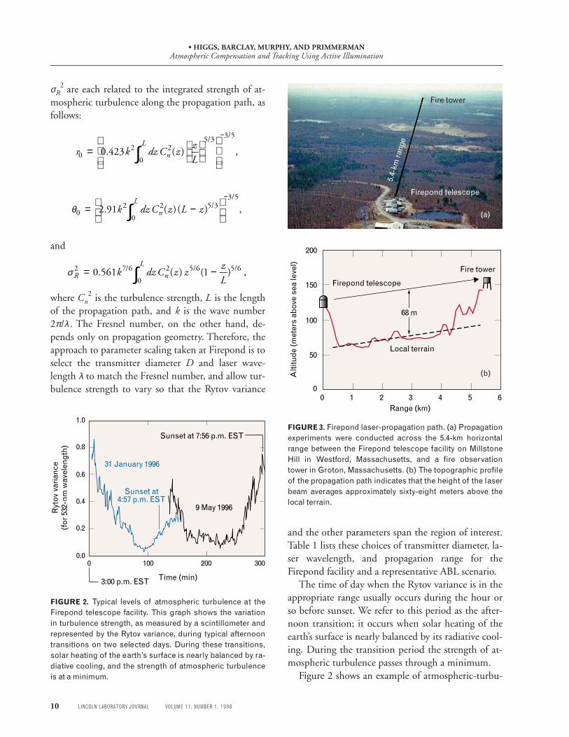
of the propagation path, and k is the wave number2π/λ. The Fresnel number, on the other hand, de-pends only on propagation geometry. Therefore, theapproach to parameter scaling taken at Firepond is toselect the transmitter diameter D and laser wave-length λ to match the Fresnel number, and allow tur-bulence strength to vary so that the Rytov variance
and the other parameters span the region of interest.Table 1 lists these choices of transmitter diameter, la-ser wavelength, and propagation range for theFirepond facility and a representative ABL scenario.
The time of day when the Rytov variance is in theappropriate range usually occurs during the hour orso before sunset. We refer to this period as the after-noon transition; it occurs when solar heating of theearth’s surface is nearly balanced by its radiative cool-ing. During the transition period the strength of at-mospheric turbulence passes through a minimum.
Figure 2 shows an example of atmospheric-turbu-
FIGURE 2. Typical levels of atmospheric turbulence at theFirepond telescope facility. This graph shows the variationin turbulence strength, as measured by a scintillometer andrepresented by the Rytov variance, during typical afternoontransitions on two selected days. During these transitions,solar heating of the earth’s surface is nearly balanced by ra-diative cooling, and the strength of atmospheric turbulenceis at a minimum.
30020010000.0
0.2
0.4
0.6
0.8
1.0
Time (min)
Ryt
ov v
aria
nce
(for
532
-nm
wav
elen
gth)
31 January 1996
9 May 1996
3:00 p.m. EST
Sunset at4:57 p.m. EST
Sunset at 7:56 p.m. ESTFIGURE 3. Firepond laser-propagation path. (a) Propagationexperiments were conducted across the 5.4-km horizontalrange between the Firepond telescope facility on MillstoneHill in Westford, Massachusetts, and a fire observationtower in Groton, Massachusetts. (b) The topographic profileof the propagation path indicates that the height of the laserbeam averages approximately sixty-eight meters above thelocal terrain.
0
50
100
150
200
0 1 2 3 4 5 6Range (km)
Alti
tude
(met
ers
abov
e se
a le
vel)
68 m
Local terrain
Fire tower
Firepond telescope
Fire tower
Firepond telescope
5.4-
km r
ange
(a)
(b)

• HIGGS, BARCLAY, MURPHY, AND PRIMMERMANAtmospheric Compensation and Tracking Using Active Illumination
VOLUME 11, NUMBER 1, 1998 LINCOLN LABORATORY JOURNAL 11
FIGURE 4. Firepond experimental configuration. Laser beams from the nine-beam track illuminator (blue) and the four-beamadaptive-optics illuminator (green) propagate from one quadrant of the Firepond telescope primary mirror across the 5.4-kmtest range to illuminate the scaled missile model in the fire tower. Backscatter from the missile is collected within a 15-cm aper-ture in another quadrant on the Firepond telescope primary mirror and directed to the imaging tracker and the wavefront sensor.The scoring-laser beam (red), which substitutes for the high-energy ABL in these experiments, samples the steering and de-formable mirrors to receive its tilt and high-order correction, and is directed back toward the missile and the diagnostics in thefire tower.
lence data for two selected days. The plot is a tempo-ral history of the scintillation strength, presented hereas Rytov variance. The raw data were recorded at ten-second intervals by a scintillometer lent to LincolnLaboratory by the National Oceanic and Atmo-spheric Administration (NOAA) Wave PropagationLaboratory [6]. The NOAA scintillometer compriseda 0.95-µm diode laser and transmitter located at theFirepond facility, and a 20-cm-diameter receiver lo-cated in the fire tower. The scintillometer provides ameasure of the average value of the atmospheric tur-bulence strength Cn
2 along the propagation path at1-Hz rate. With an appropriate choice of wavelengthand receiver diameter, the instrument can provide re-liable estimates of turbulence strength up to a Rytovvariance of nearly one. Beyond that value, saturation
effects begin to reduce its accuracy. In addition to thescintillometer at the Firepond facility, we equippedeach end of the propagation path with instruments tomeasure wind speed and direction, temperature, andrelative humidity, which gave us additional importantinformation about weather-related factors that influ-ence turbulence and scintillation.
Figure 3 shows the topography along the laser-propagation path from the Firepond facility to thefire tower in Groton. The height of the laser beamabove the local terrain is approximately sixty-eightmeters over most of the path; terrain under the beamis mainly coniferous forest. On the basis of the uni-formity of the terrain and the height of the beamabove ground, we believe the turbulence is reasonablyconstant along the path.
Wavefront sensor(views adaptive-optics illuminator
return from missile nose tip)
Four-beam illuminatorfor adaptive optics
(514-nm wavelength)
Imaging tracker(views image of
illuminated missile)
Fire tower
Nine-beam Illuminatorfor tracking
(488-nm wavelength)
Firepond telescope
Fast-steering mirror
241-actuatordeformable mirror
5.4-km propagation range
Scaledmissilemodel
Scoring laser
Far-fieldcamera
Centroiddetector
Target-plane diagnostics
Imaging optics
• HIGGS, BARCLAY, MURPHY, AND PRIMMERMANAtmospheric Compensation and Tracking Using Active Illumination
12 LINCOLN LABORATORY JOURNAL VOLUME 11, NUMBER 1, 1998
Experimental Configuration
Figure 4 shows a diagram of the Firepond active-tracking and adaptive-optics compensation facilityand horizontal propagation range. The 488-nm out-put from the multibeam track illuminator is mergedinto the Coudé path of the Firepond telescope andmade to propagate from a 20-cm subaperture in thelower quadrant of the primary mirror. Similarly, the514-nm output from the multibeam adaptive-opticsilluminator is made to propagate from the right quad-rant of the primary mirror. The track-illuminator andadaptive-optics-illuminator configurations are dis-cussed in greater detail below.
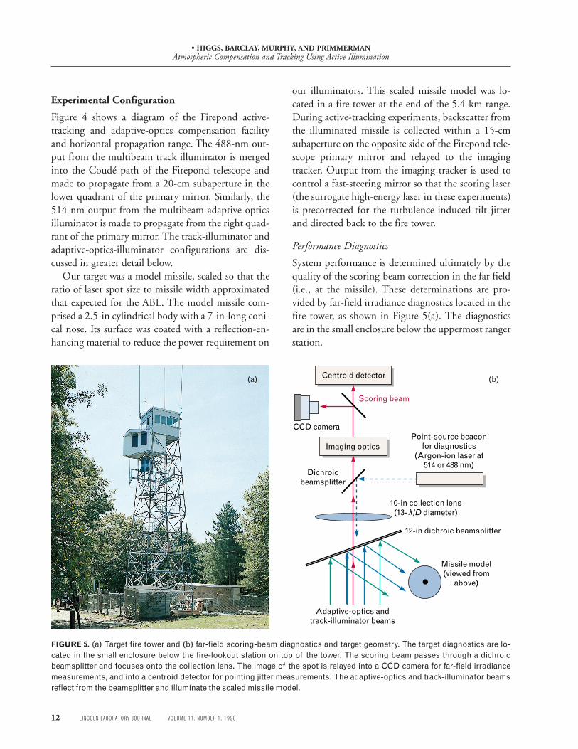
Our target was a model missile, scaled so that theratio of laser spot size to missile width approximatedthat expected for the ABL. The model missile com-prised a 2.5-in cylindrical body with a 7-in-long coni-cal nose. Its surface was coated with a reflection-en-hancing material to reduce the power requirement on
FIGURE 5. (a) Target fire tower and (b) far-field scoring-beam diagnostics and target geometry. The target diagnostics are lo-cated in the small enclosure below the fire-lookout station on top of the tower. The scoring beam passes through a dichroicbeamsplitter and focuses onto the collection lens. The image of the spot is relayed into a CCD camera for far-field irradiancemeasurements, and into a centroid detector for pointing jitter measurements. The adaptive-optics and track-illuminator beamsreflect from the beamsplitter and illuminate the scaled missile model.
our illuminators. This scaled missile model was lo-cated in a fire tower at the end of the 5.4-km range.During active-tracking experiments, backscatter fromthe illuminated missile is collected within a 15-cmsubaperture on the opposite side of the Firepond tele-scope primary mirror and relayed to the imagingtracker. Output from the imaging tracker is used tocontrol a fast-steering mirror so that the scoring laser(the surrogate high-energy laser in these experiments)is precorrected for the turbulence-induced tilt jitterand directed back to the fire tower.
Performance Diagnostics
System performance is determined ultimately by thequality of the scoring-beam correction in the far field(i.e., at the missile). These determinations are pro-vided by far-field irradiance diagnostics located in thefire tower, as shown in Figure 5(a). The diagnosticsare in the small enclosure below the uppermost rangerstation.
(a)
Missile model(viewed from
above)
Point-source beaconfor diagnostics
(Argon-ion laser at514 or 488 nm)
Dichroicbeamsplitter
12-in dichroic beamsplitter
Imaging optics
CCD camera
Centroid detector
10-in collection lens(13- /D diameter) λ
Adaptive-optics and track-illuminator beams
Scoring beam
(b)
• HIGGS, BARCLAY, MURPHY, AND PRIMMERMANAtmospheric Compensation and Tracking Using Active Illumination
VOLUME 11, NUMBER 1, 1998 LINCOLN LABORATORY JOURNAL 13
Figure 5(b) illustrates the scoring-beam diagnosticsand the target-plane geometry for illuminating thescaled missile model. Dichroic beamsplitters directthe scoring beam into the diagnostics and the illumi-nators toward the missile model. These beamsplittersalso permit the transmission of a point-source beaconused for baseline performance measurements and fordiagnostic comparisons. The image of the scoring-beam far-field irradiance is relayed into a 128 × 128-pixel CCD camera and a centroid detector. Both theCCD camera and the centroid detector have 13-λ/Dfields of view, determined by the imaging optics andthe collection lens. Data analyses have shown that thisfield of view is sufficient for closed-loop measure-ments of scoring-beam characteristics up to a Rytovvariance of about 0.7. At higher levels of turbulence,spillover of the scoring beam outside the collectionlens reduces the accuracy of the measurements.
Adaptive-Optics and Imaging-Tracker Configuration
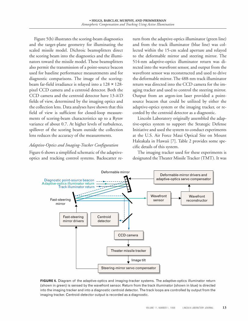
Figure 6 shows a simplified schematic of the adaptive-optics and tracking control systems. Backscatter re-
turn from the adaptive-optics illuminator (green line)and from the track illuminator (blue line) was col-lected within the 15-cm scaled aperture and relayedto the deformable mirror and steering mirror. The514-nm adaptive-optics illuminator return was di-rected into the wavefront sensor, and output from thewavefront sensor was reconstructed and used to drivethe deformable mirror. The 488-nm track illuminatorreturn was directed into the CCD camera for the im-aging tracker and used to control the steering mirror.Output from an argon-ion laser provided a point-source beacon that could be utilized by either theadaptive-optics system or the imaging tracker, or re-corded by the centroid detector as a diagnostic.
Lincoln Laboratory originally assembled the adap-tive-optics system to support the Strategic DefenseInitiative and used the system to conduct experimentsat the U.S. Air Force Maui Optical Site on MountHaleakala in Hawaii [7]. Table 2 provides some spe-cific details of this system.
The imaging tracker used for these experiments isdesignated the Theater Missile Tracker (TMT). It was
FIGURE 6. Diagram of the adaptive-optics and imaging-tracker systems. The adaptive-optics illuminator return(shown in green) is sensed by the wavefront sensor. Return from the track illuminator (shown in blue) is directedinto the imaging tracker and into a diagnostic centroid detector. The track loops are controlled by output from theimaging tracker. Centroid-detector output is recorded as a diagnostic.
Fast-steeringmirror
Fast-steeringmirror drivers
Wavefrontsensor
CCD camera
Wavefrontreconstructor
Deformable-mirror drivers andadaptive-optics servo compensator
Centroiddetector
Steering-mirror servo compensator
Image tilt
Deformable mirror
Adaptive-optics illuminator returnTrack illuminator return
Diagnostic point-source beacon
Theater missile tracker

• HIGGS, BARCLAY, MURPHY, AND PRIMMERMANAtmospheric Compensation and Tracking Using Active Illumination
14 LINCOLN LABORATORY JOURNAL VOLUME 11, NUMBER 1, 1998
designed and built at the Air Force Phillips Labora-tory and specifically configured to utilize output froma CCD camera built by Lincoln Laboratory. Essen-tially, the TMT is a high-speed data processor de-signed around a Mercury Quad i860s digital signalprocessor board. A Force Sparc 2c host workstationprovides the user interface and is used for data post-processing and algorithm development.
The TMT can perform centroid calculations atframe rates of 1 kHz with missile-image data from theentire 64 × 64-pixel focal-plane array, or process a16 × 16-pixel windowed subset of the data at a framerate of 2 kHz. Other track algorithms have beenimplemented on the TMT, including the full, win-dowed, and binary centroid algorithms, and threevariations of a correlation algorithm.
During closed-loop tracking, tilt error signals com-puted by the TMT are scaled appropriately and input
to a Type-1 servo system. The servo-system outputthen provides the drive signals to control the pointingof a fast-steering mirror. Error-rejection measure-ments made with this tracking system show that itsclosed-loop bandwidth (0-dB crossover) is approxi-mately 90 Hz. Table 3 provides some specific detailsof the TMT tracker.
Tracker and Adaptive-OpticsIlluminator Configuration
Figure 7 illustrates the transmitter and target-planebeam profiles of the illuminator laser beams. The leftside of the figure represents the Firepond telescope48-in primary mirror, and shows how the multibeamilluminator for tracking propagates from the upperquadrant. The multibeam footprint is containedwithin a 20-cm-diameter circle and comprises nineindividual 4-cm beams. Each beam, which is incoher-ent with respect to the others, is propagated to thetarget to form a 50-cm footprint on the missilemodel, as shown in the right side of the figure. Thebeams are aligned so that all the far-field patternsoverlap on target.
Similarly, the multibeam illuminator for adaptiveoptics is propagated from the right quadrant of theprimary mirror. Its footprint comprises four indi-vidual 4-cm beams contained within a 15-cm-diam-eter circle. As with the track illuminator, each adap-tive-optics illuminator beam is incoherent withrespect to the other beams. As indicated in the right
Table 2. Adaptive-Optics System Specifications
Deformable Mirror
Design ULE floating facesheetPMN actuators
Number of actuators 341 (241 active, 100 support)
Geometry 21 × 21 without corners
Stroke 4 microns
Wavefront Sensor
Type HartmannToe-to-tail configuration
Geometry 218 x-gradients218 y-gradients
Detectors Two 64 × 64 silicon CCDs3-kHz sampling rate
Dynamic range ±2 waves per subaperture
Reconstructor and Servo
Type Matrix multiply
Servo design Type 1 with digital accumulator
Bandwidth 120 Hz (0-dB crossover)
Table 3. Tracker System Specifications
Design Imaging
Detector 64 × 64-pixel silicon CCD
Pixel field of view 0.5 λ/D (1.7 microrad)
Algorithms supported Centroid(full, windowed, binary)Leading edge, correlation
Processor Mercury Quad i860swith Sparc 2c host
Servo Type 1
Bandwidth 90 Hz (0-dB crossover)

• HIGGS, BARCLAY, MURPHY, AND PRIMMERMANAtmospheric Compensation and Tracking Using Active Illumination
VOLUME 11, NUMBER 1, 1998 LINCOLN LABORATORY JOURNAL 15
figure, each beam is directed toward the missilemodel and aligned so that all the far-field patternsoverlap to form a 10-cm spot.
The reflected return from both illuminators is col-lected within a 15-cm scaled aperture located in thelower quadrant of the primary mirror. The outgoingscoring beam is propagated from this same apertureand directed back along the path of the adaptive-op-tics illuminator return.
Having the multibeam illuminators in one sectionof the Firepond telescope and the scoring beam in aseparate section is not just an experimental conve-nience. It also results in the track illuminator experi-encing a different atmospheric-turbulence profilefrom that seen by the scoring beam. This feature isimportant in order for the Firepond experiments tosimulate ABL scenarios properly. For the ABL, the il-luminators are likely to share the same transmittingaperture as the high-energy laser. The motion of theaircraft and target during the round-trip time offlight, however, will mean that the outgoing illumina-tors will not follow the same path as the high-energylaser and will not, therefore, be corrected for atmo-spheric turbulence.
Test Overview
We performed our initial tests with point-source bea-cons for both adaptive-optics and tracking, as dis-cussed earlier in the article. Results from these testsdemonstrated for the first time the feasibility of adap-tive-optics compensation under atmospheric-turbu-lence conditions expected for the ABL. Point-source-beacon results also provided baseline performancemeasurements against which the active-tracking andactive-compensation results could be compared.
The first active-illumination tests addressed track-ing issues. A nine-beam illuminator (provided byLockheed-Martin) was installed along with the TMTimaging tracker. The adaptive-optics system contin-ued to utilize the point-source beacon. In the begin-ning we performed tests with a number of differenttrack-illuminator configurations. Initially, the missilemodel was illuminated with a single illuminator; sub-sequent tests were performed with four-beam andnine-beam illumination. Results from these measure-ments have quantified the benefits of multibeam illu-mination for tracking [3].
Following the illuminator-configuration tests, weperformed active-tracking tests to compare a varietyof different tracking algorithms. All these tests wereconfigured for nine-beam illumination. Data were re-corded while using the conventional centroid algo-rithm, as well as variations such as the binary centroidalgorithm. Various correlation algorithms were com-pared along with a number of algorithms supplied bythe ABL contractor. Results of these tests are not re-ported here.
Next we installed a second multibeam illuminatorfor the adaptive-optics system. To simplify experi-mental procedures, we performed initial active-com-pensation tests with active illumination while thetracking was done with the point-source beacon.These tests addressed the impact of the extended tar-get on adaptive-optics performance [4]. Data were re-corded over a wide range of Rytov variances and withtwo adaptive-optics illuminator configurations:single-beam and four-beam illumination.
Finally, we performed tests with a configurationclosely resembling that planned for the actual ABLsystem: one multibeam illuminator for tracking and a
FIGURE 7. Transmitter and target-plane laser beam geom-etry. The drawing on the left indicates the positions of thenine-beam track illuminator, the four-beam adaptive-opticsilluminator, and the scoring beam on the primary mirror ofthe Firepond 48-in telescope. The drawing on the right indi-cates the target-plane footprints of these beams as they fallon the scaled missile model in the fire tower.
Nine-beam illuminatorfor tracking
Four-beam illuminatorfor adaptive optics
Firepond telescopeprimary mirror
Beam footprintat target
Transmitter/receiver aperture

• HIGGS, BARCLAY, MURPHY, AND PRIMMERMANAtmospheric Compensation and Tracking Using Active Illumination
16 LINCOLN LABORATORY JOURNAL VOLUME 11, NUMBER 1, 1998
second multibeam illuminator for adaptive-opticscompensation. Results from these tests demonstratethat conventional adaptive-optics and tracking, per-formed with active illumination of the target missile,effectively compensate turbulence-induced phase andtilt fluctuations under ABL conditions.
Active-Tracking Experimental Results
The discussion of our active-tracking results beginswith an overview of tests designed to compare differ-ent illuminator configurations. Both open-loop andclosed-loop tests were performed with either single-beam, four-beam, or nine-beam illumination; thesetests were designed to quantify the performance ben-efits of multibeam illumination. The tracker utilizedthe conventional centroid algorithm for all illumina-tor comparison tests.
Open-Loop Imagery
Before the TMT tracker was integrated into theFirepond tracking system, we made preliminary mea-surements to help quantify the effects of multibeamillumination and to prepare for closed-loop active-tracking tests. For these measurements, all performedopen loop (i.e., with the tracking servos off ), we illu-minated the missile model with either one or nine il-luminator beams, and collected images under a vari-ety of atmospheric-turbulence strengths. Data wererecorded over a range of Rytov variances between ap-proximately 0.07 and 0.6. Each data record containedabout 120 CCD images at a resolution of 64 × 64pixels and an integration time of one millisecond.
Figure 8 shows one example of these image data, inthis case for Rytov variance of approximately 0.2. Theimage in Figure 8(a) was recorded with only a singlebeam illuminating the missile model; the image inFigure 8(b) was recorded with nine illuminatingbeams. Both images are taken from single frames ofthe CCD camera. The image in Figure 8(b) illustratesthe ability of a multibeam illuminator to reduce im-age scintillation; the image is a better resemblance ofthe missile nose tip, but is still distorted. Images likethese clearly demonstrate that, even with the im-provement provided by multibeam illumination, pre-cision tracking under ABL conditions is a difficultchallenge.
Open-Loop Spectra
The reduction in scintillation and its benefit to animaging tracker can be quantified by comparing tilt-jitter spectra derived simultaneously from missile-image data (like those shown in Figure 8) and point-source-beacon data. Figure 9 shows such a compari-son. In this case, a single beam was used to illuminatethe scaled missile model during moderate turbulence(the Rytov variance was approximately 0.2). With thetrack loops open, we recorded thirteen-second timehistories of data from the imaging tracker (viewingthe illuminated missile model) and simultaneous datafrom the centroid detector (viewing the pointsource).
Figure 9(a) compares a tilt spectrum for themissile’s transverse axis with a spectrum derived fromthe simultaneously recorded point-source data. Fig-ure 9(b) shows a similar comparison for the missile’slongitudinal axis. Tilt errors derived from the missile’s
FIGURE 8. Missile model images produced with (a) single-beam illumination and (b) nine-beam illumination. Thedrawing in each figure shows the shape and orientation ofthe nose tip. In both cases the total illuminator power wasthe same. Multibeam illumination of the missile model re-duces image scintillation, but the image is still distorted.
(a)
(b)

• HIGGS, BARCLAY, MURPHY, AND PRIMMERMANAtmospheric Compensation and Tracking Using Active Illumination
VOLUME 11, NUMBER 1, 1998 LINCOLN LABORATORY JOURNAL 17
transverse axis clearly resemble those of the pointsource, and have similar cumulative power: 0.94 and0.76 λ /D rms, respectively. Given the narrow angularextent of the missile’s transverse axis, this result is notsurprising.
This similarity of the missile’s transverse-axis tiltspectrum to that of a point source does not, however,extend to the missile’s longitudinal axis. Comparisonof the two tilt spectra reveals a significant increase incumulative power for tilt signals derived from the il-luminated missile image: 1.5 λ/D rms from the mis-
sile image versus 0.98 λ /D for the point source. Thisincrease in tilt jitter, which starts at frequencies near10 Hz and extends out to the noise floor of the instru-ments, is the direct result of the scintillation seen inthe images recorded with single-beam illuminationshown in Figure 8(a).
Figure 10 shows a similar comparison when ninebeams are used to illuminate the scaled missile model.All these data were recorded open loop under moder-ate turbulence conditions (the Rytov variance was ap-proximately 0.23).
FIGURE 9. Comparison of point-source jitter spectra andmissile-image jitter spectra using single-beam illuminationof the missile model. Results are shown for (a) the missile’stransverse axis and (b) the longitudinal axis. The tilt spectrawere calculated from simultaneously recorded output fromthe imaging tracker and the centroid detector. The imagingtracker viewed only the illuminated missile; the centroid de-tector viewed the point-source beacon.
FIGURE 10. Comparison of point-source jitter spectra andmissile-image jitter spectra using nine-beam illumination ofthe missile model. Results are shown for (a) the missile’stransverse axis and (b) the longitudinal axis. The missile-im-age jitter spectra and the point-source jitter spectra were si-multaneously recorded, similar to the way the jitter spectradata for single-beam illumination tests were recorded in Fig-ure 9.
100010010110–6
10–5
10–4
10–3
10–2
10–1
100
Missile image 0.94 /D rms
Pow
er s
pect
ral d
ensi
ty [(
/D
)2 / H
z]
1000100101
Missile image 1.5 /D rms
Point source 0.76 /D rms
Point source 0.98 /D rms
Frequency (Hz)
Pow
er s
pect
ral d
ensi
ty [(
/D
)2 / H
z]
λ
λ
λ
λ
λ
10–6
10–5
10–4
10–3
10–2
10–1
100
λ
(a)
(b)
Transverse axis
Longitudinal axis
10–6
10–5
10–4
10–3
10–2
10–1
100
Pow
er s
pect
ral d
ensi
ty [(
/D
)2 / H
z]
100010010110–6
10–5
10–4
10–3
10–2
10–1
100
Frequency (Hz)
Pow
er s
pect
ral d
ensi
ty [(
/D
)2 / H
z]
1000100101
Missile image 0.83 /D rms
Missile image 0.76 /D rms
Point source 0.76 /D rms
Point source 0.82 /D rms
λ
λ
λ
λ
λ
(a)
λ
(b)
Transverse axis
Longitudinal axis
• HIGGS, BARCLAY, MURPHY, AND PRIMMERMANAtmospheric Compensation and Tracking Using Active Illumination
18 LINCOLN LABORATORY JOURNAL VOLUME 11, NUMBER 1, 1998
As with the single-beam illumination spectra datashown in Figure 9, tilt power spectra derived from thetransverse axis of the missile are similar to those com-puted from point-source tilt data. Both contain aboutthe same cumulative power: approximately 0.83 and0.76 λ /D rms, respectively. With nine-beam illumi-nation, however, this similarity in tilt spectra now ex-tends to the longitudinal axis as well. The overall cu-mulative powers are similar: 0.76 λ/D rms for the
missile versus 0.82 λ /D for the point source. The im-portant point is that illumination with nine beamshas significantly reduced the scintillation that mightotherwise appear as tilt to the imaging tracker.
Closed-Loop Comparisons
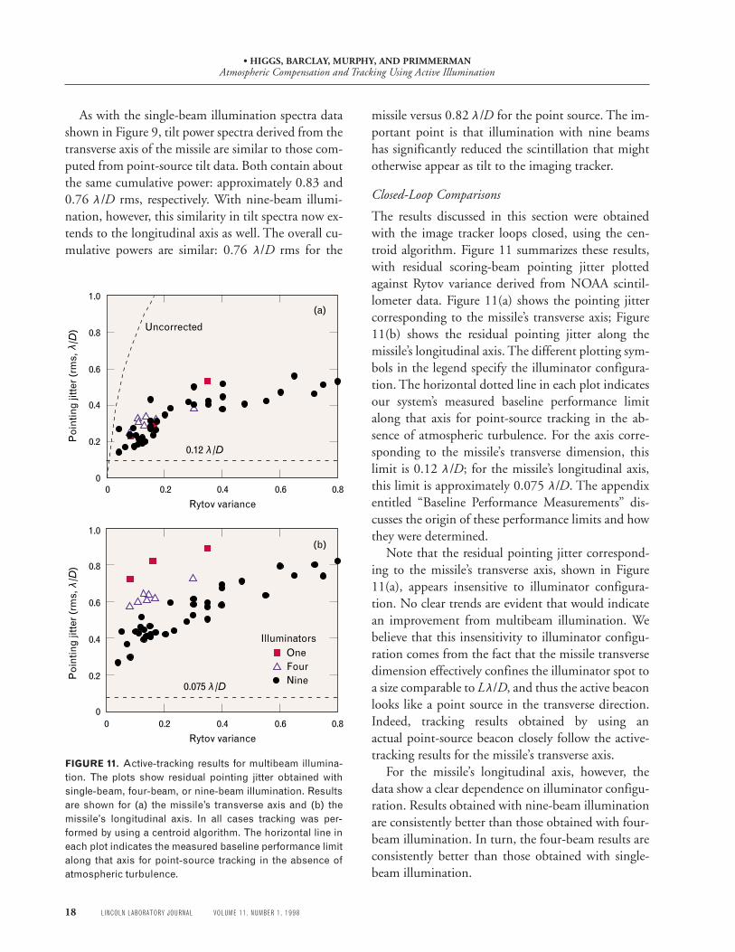
The results discussed in this section were obtainedwith the image tracker loops closed, using the cen-troid algorithm. Figure 11 summarizes these results,with residual scoring-beam pointing jitter plottedagainst Rytov variance derived from NOAA scintil-lometer data. Figure 11(a) shows the pointing jittercorresponding to the missile’s transverse axis; Figure11(b) shows the residual pointing jitter along themissile’s longitudinal axis. The different plotting sym-bols in the legend specify the illuminator configura-tion. The horizontal dotted line in each plot indicatesour system’s measured baseline performance limitalong that axis for point-source tracking in the ab-sence of atmospheric turbulence. For the axis corre-sponding to the missile’s transverse dimension, thislimit is 0.12 λ /D; for the missile’s longitudinal axis,this limit is approximately 0.075 λ/D. The appendixentitled “Baseline Performance Measurements” dis-cusses the origin of these performance limits and howthey were determined.
Note that the residual pointing jitter correspond-ing to the missile’s transverse axis, shown in Figure11(a), appears insensitive to illuminator configura-tion. No clear trends are evident that would indicatean improvement from multibeam illumination. Webelieve that this insensitivity to illuminator configu-ration comes from the fact that the missile transversedimension effectively confines the illuminator spot toa size comparable to Lλ/D, and thus the active beaconlooks like a point source in the transverse direction.Indeed, tracking results obtained by using anactual point-source beacon closely follow the active-tracking results for the missile’s transverse axis.
For the missile’s longitudinal axis, however, thedata show a clear dependence on illuminator configu-ration. Results obtained with nine-beam illuminationare consistently better than those obtained with four-beam illumination. In turn, the four-beam results areconsistently better than those obtained with single-beam illumination.
FIGURE 11. Active-tracking results for multibeam illumina-tion. The plots show residual pointing jitter obtained withsingle-beam, four-beam, or nine-beam illumination. Resultsare shown for (a) the missile’s transverse axis and (b) themissile’s longitudinal axis. In all cases tracking was per-formed by using a centroid algorithm. The horizontal line ineach plot indicates the measured baseline performance limitalong that axis for point-source tracking in the absence ofatmospheric turbulence.
0.80.60.40.200
0.2
0.4
0.6
0.8
1.0
0.80.60.40.200
0.2
0.4
0.6
0.8
1.0
Rytov variance
Rytov variance
Poi
ntin
g jit
ter (
rms,
/D
)P
oint
ing
jitte
r (rm
s,
/D)
OneFourNine
Illuminators
(b)
(a)
Uncorrected
λλ
0.12 /Dλ
0.075 /Dλ

• HIGGS, BARCLAY, MURPHY, AND PRIMMERMANAtmospheric Compensation and Tracking Using Active Illumination
VOLUME 11, NUMBER 1, 1998 LINCOLN LABORATORY JOURNAL 19
Active-Compensation Experimental Results
As we discussed earlier, active-compensation tests uti-lized a second illuminator to provide the beacon forthe adaptive-optics system, as shown in Figure 4. Forthese tests the adaptive-optics illuminator at 514-nmwavelength (in this case providing four beams) wasinserted into the Coudé path at the base of the tele-scope tower and made to propagate from the rightquadrant of the telescope primary.
The design of the four-beam illuminator for adap-tive optics is similar to the nine-beam track illumina-tor—each of the four separate beams is incoherentwith respect to the others, and each is aligned so as tooverlap on the scaled missile model. One importantdifference, however, is that—unlike the track illumi-nator that provides flood illumination of the mis-sile—the adaptive-optics illuminator forms a smallspot at a selected location on the missile body, as illus-trated earlier in Figure 7. Backscatter from the adap-tive-optics illuminator was collected within the same15-cm aperture used to propagate the scoring beam,and imaged into the wavefront sensor. Output fromthe wavefront sensor was used to control the surfaceof a deformable mirror to correct for the instanta-neous phasefront error caused by turbulence. Whenthe scoring beam was reflected from this deformablemirror, it was precorrected for the turbulence it expe-rienced as it propagated back to the target.
Minimizing the size of the adaptive-optics illumi-nator spot on the missile body is an important con-cern, because the adaptive-optics system performsbest when it views light from as small a spot as pos-sible, preferably a diffraction-limited point source. Asthe size of the adaptive-optics beacon approaches andperhaps exceeds the isoplanatic patch size (the spotsize subtended by the isoplanatic angle θ0), the abilityto correct the outgoing scoring beam is reduced. Thisproblem occurs because light originating from differ-ent locations within the illuminator spot travelsthrough different atmospheric paths and therefore ex-periences different turbulence aberrations along theway to the receiver aperture. As a result, the phasemeasured by the wavefront sensor is not representa-tive of the turbulence-induced phase distortion expe-rienced by the outgoing scoring beam.
Adaptive-Optics Illuminator Comparisons
To quantify the advantages, if any, of using multi-beam illumination to provide the adaptive-optics bea-con, we made measurements by using either a singleadaptive-optics illuminator or a four-beam illumina-tor. These tests were performed by using active illumi-nation for the adaptive-optics system, while using apoint-source beacon for the tracker.
Figure 12 shows the results of these comparisons.The data are scoring-beam Strehl ratio (the ratio ofthe measured peak intensity to that expected for a dif-fraction-limited spot) versus Rytov variance for threedifferent configurations. Results obtained by using asingle adaptive-optics illuminator are shown as theopen triangles; results obtained by using four-beamillumination are shown as solid triangles. For boththese cases, tracking was performed by using a point-source beacon. Results obtained by using a point-source beacon for both adaptive optics and trackingare shown by open circles.
Although we collected only a few data points withsingle-beam illumination, we can draw some tenta-tive conclusions. The two single-beam data pointsnear Rytov variance values of 0.45 and 0.60, respec-
FIGURE 12. Results from adaptive-optics illuminator com-parisons. The figure shows the scoring-beam Strehl ratioplotted versus Rytov variance. Results obtained by using asingle adaptive-optics illuminator are indicated by the opentriangles; results obtained by using four-beam illuminationare indicated by solid triangles. The tracker utilized a point-source beacon for both tests. Earlier point-source-beaconresults are indicated by the open circles.
0
0.2
0.4
0.6
0.8
1
0 0.2 0.4 0.6 0.8
Point-source beaconSingle-beam illuminationFour-beam illumination
Rytov variance
Sco
ring
-bea
m S
treh
l rat
io

• HIGGS, BARCLAY, MURPHY, AND PRIMMERMANAtmospheric Compensation and Tracking Using Active Illumination
20 LINCOLN LABORATORY JOURNAL VOLUME 11, NUMBER 1, 1998
tively, suggest that single-beam and four-beam per-formance are approximately the same. The twosingle-beam data points near Rytov variance values of0.08 and 0.18, however, suggest a slight decrease inperformance when single-beam illumination is used.
We believe this decreased performance results fromthe signal fading associated with single-beam illumi-nation. Figure 13 shows an example of the perfor-mance degradation associated with the fading ob-served when we use a single-beam adaptive-opticsilluminator. The left figure shows a two-second tem-poral history of the average wavefront-sensor pupil-plane intensity. The wavefront-sensor data were re-corded at a frame rate of 2 kHz, but were temporallyrebinned to match the 50-Hz recording rate of thescoring-beam far-field irradiance camera. From eachframe of the scoring-beam CCD data we computedan instantaneous Strehl ratio. The temporal history ofthat Strehl ratio is shown in the right side of Figure13. The degree of temporal correlation between thesetwo signals is most apparent during periods of fadingnear times from 0.1 to 0.3 seconds.
Illuminator comparisons aside, one striking featureapparent in the results of Figure 12 is the rather lowlevel of performance in general. Strehl ratios overmost of the ABL range of interest (Rytov variance ap-proximately 0.1 to 0.5) are between 0.3 and 0.15. Weobserved this level of performance during our initialpoint-source beacon tests [2], and attributed the re-sults to strong scintillation that is characteristic of
many ABL propagation scenarios. The wavefront-sensor pupil-plane intensity profiles in Figure 14 areexamples of this scintillation. The left image showsresults obtained with weak turbulence (Rytov vari-ance is approximately 0.05). Although some degree ofintensity nonuniformity is evident, the wavefront-sensor pupil is well filled. The right image shows re-sults obtained with stronger turbulence (Rytov vari-ance is approximately 0.4). The intensity scintillationis dramatic; some regions of the wavefront-sensor pu-pil are saturated, while many other regions are illumi-nated at levels below what is required to make a goodphase measurement. The precise impact of this scin-tillation on adaptive-optics performance depends on
FIGURE 13. Comparison of average wavefront-sensor pupil-plane intensity and scoring-beam Strehl ratio. The leftplot shows a two-second temporal history of the average wavefront-sensor pupil-plane irradiance. The data wererebinned to match the 50-Hz recording rate of the scoring-beam diagnostics. The right plot shows scoring-beamStrehl ratio measured during the same two-second period. The degree of temporal correlation between these twosignals is most apparent during periods of fading between 0.1 and 0.3 sec.
FIGURE 14. Examples of wavefront-sensor pupil-plane in-tensity profiles. Each image was produced from a singleframe of wavefront-sensor subaperture intensity data. Theintegration time was half a millisecond. The left image wasrecorded under weak turbulence conditions (Rytov varianceapproximately 0.05); the right image was recorded duringstronger turbulence (Rytov variance approximately 0.4).
Time (sec)
Ave
rage
wav
efro
nt-
se
nsor
inte
nsity
(cou
nts)
0.0 0.5 1.0 1.5 2.0
1500
1000
500
0
Mea
sure
d S
treh
l rat
io
0.0 0.5 1.0 1.5 2.0
1.0
0.8
0.6
0.4
0.2
0.0
Time (sec)

• HIGGS, BARCLAY, MURPHY, AND PRIMMERMANAtmospheric Compensation and Tracking Using Active Illumination
VOLUME 11, NUMBER 1, 1998 LINCOLN LABORATORY JOURNAL 21
such factors as wavefront-sensor dynamic range andnoise characteristics, as well as servo temporal band-width. Those details are not discussed here. As illus-trated in the qualitative examples shown in Figure 14,however, the strong scintillation clearly poses a diffi-cult challenge for the adaptive-optics system.
This source of performance degradation was notunexpected; results from simulations that model theadaptive-optics hardware response to strong scintilla-tion predict similar levels of low performance. Inaddition, analytical studies [8] show that the scintilla-tion is accompanied by beacon-phasefront disconti-nuities known as branch points. These studies showthat the stronger the scintillation, the higher theprobability of branch-point occurrence. Becausebranch points are not handled properly by conven-tional adaptive-optics wavefront reconstructors, sys-tem performance is degraded by their presence.
Expected ABL Configuration
We conducted a number of tests in which both theadaptive optics and the tracking were performed withactive illumination. The adaptive-optics beacon wasprovided by using four-beam illumination, and track-
ing was performed by using nine-beam illumination,as shown earlier in Figure 7.
Figure 15 shows sample scoring-beam far-field ir-radiance profiles. Output from the scoring-beam di-agnostics camera was recorded for three seconds andused to form these composite images. The upper halfof the figure shows results obtained without eitheradaptive-optics or tracking compensation. The far-field irradiance profiles are presented as mesh plots(left) and as false-color images (right). The Strehl ra-tio calculated from the three-second composite imageis approximately 0.04. When the adaptive-optics andtrack loops are closed, we obtain the results shown inthe lower half of the figure. In this case, the Strehl ra-tio calculated from the composite image data has in-creased to approximately 0.17.
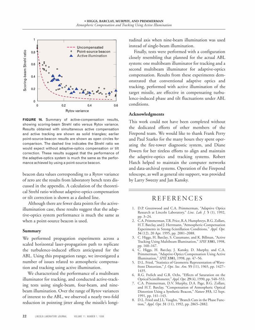
Figure 16, which shows scoring-beam Strehl ratioversus Rytov variance, summarizes the results frommany such tests. Results obtained by using active illu-mination for both adaptive-optics compensation andtracking are shown as solid triangles. For comparison,the figure also shows test results when a point-sourcebeacon was used for both adaptive-optics compensa-tion and tracking (open circles). The point-source-
FIGURE 15. Sample results from active compensation with active-tracking tests. The upper plots show a typicalscoring-beam far-field irradiance profile obtained without adaptive-optics or tracking correction. The Strehl ratio isapproximately 0.04. The lower plots show results obtained when both the adaptive-optics correction and trackingwere performed by using active illumination (four-beam illumination for the adaptive optics, and nine-beam illumi-nation for tracking). The Strehl ratio is approximately 0.17. In each case the Rytov variance was approximately 0.6.
Adaptive-optics and track loops open
Adaptive-optics and track loops closed
• HIGGS, BARCLAY, MURPHY, AND PRIMMERMANAtmospheric Compensation and Tracking Using Active Illumination
22 LINCOLN LABORATORY JOURNAL VOLUME 11, NUMBER 1, 1998
FIGURE 16. Summary of active-compensation results,showing scoring-beam Strehl ratio versus Rytov variance.Results obtained with simultaneous active compensationand active tracking are shown as solid triangles; earlierpoint-source-beacon results are shown as open circles forcomparison. The dashed line indicates the Strehl ratio wewould expect without adaptive-optics compensation or tiltcorrection. These results suggest that the performance ofthe adaptive-optics system is much the same as the perfor-mance achieved by using a point-source beacon.
0
0.2
0.4
0.6
0.8
1
0 0.2 0.4 0.6
UncompensatedPoint-source beaconActive illumination
Rytov variance
Sco
ring
-bea
m S
treh
l rat
io
beacon data values corresponding to a Rytov varianceof zero are the results from laboratory bench tests dis-cussed in the appendix. A calculation of the theoreti-cal Strehl ratio without adaptive-optics compensationor tilt correction is shown as a dashed line.
Although there are fewer data points for the active-illumination case, these results suggest that the adap-tive-optics system performance is much the same aswhen a point-source beacon is used.
Summary
We performed propagation experiments across ascaled horizontal laser-propagation path to replicatethe turbulence-induced effects anticipated for theABL. Using this propagation range, we investigated anumber of issues related to atmospheric compensa-tion and tracking using active illumination.
We characterized the performance of a multibeamilluminator for tracking, and conducted active-track-ing tests using single-beam, four-beam, and nine-beam illumination. Over the range of Rytov variancesof interest to the ABL, we observed a nearly two-foldreduction in pointing jitter along the missile’s longi-
tudinal axis when nine-beam illumination was usedinstead of single-beam illumination.
Finally, tests were performed with a configurationclosely resembling that planned for the actual ABLsystem: one multibeam illuminator for tracking and asecond multibeam illuminator for adaptive-opticscompensation. Results from these experiments dem-onstrated that conventional adaptive optics andtracking, performed with active illumination of thetarget missile, are effective in compensating turbu-lence-induced phase and tilt fluctuations under ABLconditions.
Acknowledgments
This work could not have been completed withoutthe dedicated efforts of other members of theFirepond team. We would like to thank Frank Perryand Paul Szarko for the many hours they spent oper-ating the fire-tower diagnostic system, and DianePowers for her tireless efforts to align and maintainthe adaptive-optics and tracking systems. RobertHatch helped to maintain the computer networksand data-archival systems. Operation of the Firepondtelescope, as well as general site support, was providedby Larry Sweezy and Jan Kansky.
R E F E R E N C E S1. D.P. Greenwood and C.A. Primmerman, “Adaptive Optics
Research at Lincoln Laboratory,” Linc. Lab. J. 5 (1), 1992,pp. 3–24.
2. C.A. Primmerman, T.R. Price, R.A. Humphreys, B.G. Zollars,H.T. Barclay, and J. Herrmann, “Atmospheric-CompensationExperiments in Strong-Scintillation Conditions,” Appl. Opt.34 (12), 20 Apr. 1995, pp. 2081–2088.
3. C. Higgs, H. Barclay, S. Cusumano, and K. Billman, “ActiveTracking Using Multibeam Illumination,” SPIE 3381, 1998,pp. 160–167.
4. C. Higgs, H. Barclay, J. Kansky, D. Murphy, and C.A.Primmerman, “Adaptive-Optics Compensation Using ActiveIllumination,” SPIE 3381, 1998, pp. 47–56.
5. D.L. Fried, “Statistics of Geometric Representation of Wave-front Distortion,” J. Opt. Soc. Am. 55 (11), 1965, pp. 1427–1435.
6. R.G. Frelich and G.R. Ochs, “Effects of Saturation on theOptical Scintillometer,” Appl. Opt. 29 (4), 1990, pp. 548–553.
7. C.A. Primmerman, D.V. Murphy, D.A. Page, B.G. Zollars,and H.T. Barclay, “Compensation of Atmospheric OpticalDistortion Using a Synthetic Beacon,” Nature 353, 12 Sept.1991, pp. 141–143.
8. D.L. Fried and J.L. Vaughn, “Branch Cuts in the Phase Func-tion,” Appl. Opt. 31 (11), 1992, pp. 2865–2882.

• HIGGS, BARCLAY, MURPHY, AND PRIMMERMANAtmospheric Compensation and Tracking Using Active Illumination
VOLUME 11, NUMBER 1, 1998 LINCOLN LABORATORY JOURNAL 23
A P P E N D I X :B A S E L I N E P E R F O R M A N C E M E A S U R E M E N T S
, tracking, and adap-tive-optics performance baseline, we conducted a se-ries of internal calibration tests using a fiber-optic“pseudo-star” point source installed at the f /200 fo-cus of the Firepond telescope. This internal-calibra-tion beacon is the diffraction-limited output of asingle-mode optical fiber, which can be configured toproduce either 488-nm or 514-nm light. Also in-stalled at the f /200 focus are a position sensor and aCCD camera similar to those used at the fire tower inGroton, Massachusetts, for target-plane diagnostics.The position sensor and the CCD camera record thetilt and far-field irradiance of the scoring beam whenthe tracking loops and adaptive-optics loops using thepseudo-star reference source as a beacon are closed.Under benign conditions in the laboratory (no scin-tillation and little turbulence) the performance mea-sured with these diagnostics represent the best perfor-mance we could hope to achieve; these residual errorsprovide a fundamental measure of our baseline per-formance. It is important to note, however, that thisbaseline measurement is relevant only to our currentconfiguration (i.e., servo bandwidth, sensor noise,noncommon path errors, and laboratory sources ofmechanical vibration) and does not reflect any funda-mental performance limits for the ABL.
In addition to determining performance baselines,we measured the noncommon path tilt errors, i.e., tilterrors experienced by either the scoring beam or thebeacon but not both. In our experimental configura-tion the noncommon path errors arise from twosources: (1) the scoring laser itself, including the opti-cal train that merges the output of the scoring laserinto the beacon path, and (2) the tracker optics andthe optical train leading to them. Tilt errors arisingfrom both these sources can be measured simulta-neously by folding the scoring beam back into thetracker from a point just beyond the tracker’s aper-ture-sharing element.
For each of the tracking algorithms used in the
Firepond tests, we measured the noise-equivalentangle [1]. For our typical tracker CCD signal levels,the contribution of the noise-equivalent angle to ourbaseline performance limit was small but measurable:for example, this angle was in the range of 0.005 to0.01 λ /D for the windowed centroid algorithm.
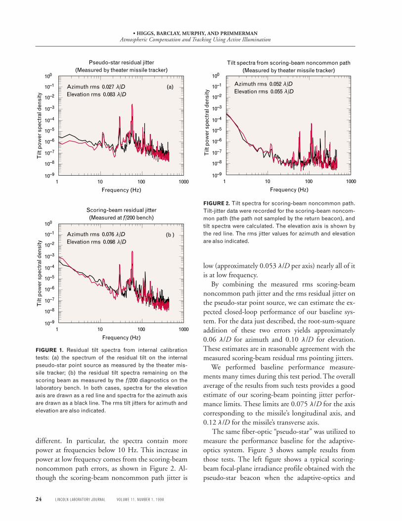
Figures 1 and 2 summarize the essential results ofour tracker performance tests. In Figure 1 we presenttypical spectra of the residual jitter when the trackingloops using the pseudo-star point source and the the-ater missile tracker are closed. In this case the theatermissile tracker employed a windowed centroid algo-rithm at a CCD frame rate of 1961 Hz. Figure 1(a)shows the closed-loop azimuth and elevation spectracalculated from the theater-missile-tracker data. Theresidual rms jitters are small: 0.027 λ/D for azimuthand 0.083 λ /D for elevation (because of the field-of-view rotation caused by the Coudé path, the elevationaxis corresponds to the missile’s transverse axis). Themost notable features in these spectra are the tilts atfrequencies near 30 and 60 Hz. Both the azimuth andelevation spectra contain a significant amount ofpower, with the elevation spectra containing the mostpower. We identified the origin of this tilt as arisingfrom a mechanical vibration. The primary contribu-tion to this vibration comes from a platform support-ing a portion of the telescope that merges the 12-cmdeformable-mirror beampath into the f /200 cone ofthe Firepond telescope. Because the 0-dB crossover inthe theater-missile-tracker error-rejection computa-tion is at approximately 90 Hz, little error rejection ofthis source of tilt error is possible.
Figure 1(b) shows the corresponding scoring-beamtilt spectra calculated from data recorded by thef /200 diagnostics on the laboratory bench. In thiscase the residual errors are somewhat larger than theresiduals reported by the theater missile tracker. Thescoring-beam azimuth and elevation rms jitters are0.076 and 0.098 λ /D, respectively. In addition to thelarger residual errors, the shape of the tilt spectra are
• HIGGS, BARCLAY, MURPHY, AND PRIMMERMANAtmospheric Compensation and Tracking Using Active Illumination
24 LINCOLN LABORATORY JOURNAL VOLUME 11, NUMBER 1, 1998
different. In particular, the spectra contain morepower at frequencies below 10 Hz. This increase inpower at low frequency comes from the scoring-beamnoncommon path errors, as shown in Figure 2. Al-though the scoring-beam noncommon path jitter is
FIGURE 1. Residual tilt spectra from internal calibrationtests: (a) the spectrum of the residual tilt on the internalpseudo-star point source as measured by the theater mis-sile tracker; (b) the residual tilt spectra remaining on thescoring beam as measured by the f/200 diagnostics on thelaboratory bench. In both cases, spectra for the elevationaxis are drawn as a red line and spectra for the azimuth axisare drawn as a black line. The rms tilt jitters for azimuth andelevation are also indicated.
FIGURE 2. Tilt spectra for scoring-beam noncommon path.Tilt-jitter data were recorded for the scoring-beam noncom-mon path (the path not sampled by the return beacon), andtilt spectra were calculated. The elevation axis is shown bythe red line. The rms jitter values for azimuth and elevationare also indicated.
low (approximately 0.053 λ/D per axis) nearly all of itis at low frequency.
By combining the measured rms scoring-beamnoncommon path jitter and the rms residual jitter onthe pseudo-star point source, we can estimate the ex-pected closed-loop performance of our baseline sys-tem. For the data just described, the root-sum-squareaddition of these two errors yields approximately0.06 λ/D for azimuth and 0.10 λ /D for elevation.These estimates are in reasonable agreement with themeasured scoring-beam residual rms pointing jitters.
We performed baseline performance measure-ments many times during this test period. The overallaverage of the results from such tests provides a goodestimate of our scoring-beam pointing jitter perfor-mance limits. These limits are 0.075 λ/D for the axiscorresponding to the missile’s longitudinal axis, and0.12 λ /D for the missile’s transverse axis.
The same fiber-optic “pseudo-star” was utilized tomeasure the performance baseline for the adaptive-optics system. Figure 3 shows sample results fromthose tests. The left figure shows a typical scoring-beam focal-plane irradiance profile obtained with thepseudo-star beacon when the adaptive-optics and
Scoring-beam residual jitter(Measured at f/200 bench)
100010010110–9
10–8
10–7
10–6
10–5
10–4
10–3
10–2
10–1
100
Frequency (Hz)
Tilt
pow
er s
pect
ral d
ensi
ty
Pseudo-star residual jitter (Measured by theater missile tracker)
100010010110–9
10–8
10–7
10–6
10–5
10–4
10–3
10–2
10–1
100
Frequency (Hz)
Tilt
pow
er s
pect
ral d
ensi
ty
Azimuth rms 0.027 /DElevation rms 0.083 /D
λλ
Azimuth rms 0.076 /DElevation rms 0.098 /D
λλ
(a)
(b )
Tilt spectra from scoring-beam noncommon path(Measured by theater missile tracker)
100010010110–9
10–8
10–7
10–6
10–5
10–4
10–3
10–2
10–1
100
Frequency (Hz)
Tilt
pow
er s
pect
ral d
ensi
ty
Azimuth rms 0.052 /DElevation rms 0.055 /D
λλ

• HIGGS, BARCLAY, MURPHY, AND PRIMMERMANAtmospheric Compensation and Tracking Using Active Illumination
VOLUME 11, NUMBER 1, 1998 LINCOLN LABORATORY JOURNAL 25
FIGURE 3. The figure on the left shows the measured scoring-beam profile (Strehl = 0.90) recorded on the adaptive-optics labo-ratory bench for the pseudo-star point-source beacon, without the effects of atmospheric turbulence and scintillation. The fig-ure on the right shows the calculated ideal diffracted-limited irradiance profile (Strehl = 1.0).
track loops are closed. This irradiance profile was de-termined from a 128-frame sequence recorded over athree-second interval. The measured Strehl ratio of0.90 provides a measurement of adaptive-optics andtracking-system performance in the absence of atmo-spheric turbulence. Other laboratory measurementsindicate this slightly degraded baseline performance isthe result of a noncommon path error in the diagnos-tic optics and a residual uncorrectable error on thesurface of the deformable mirror. For comparison, theimage on the right in Figure 3 shows the calculatedideal diffraction-limited focal-plane irradiance (Strehlratio = 1.0) we would observe for the same total flux.
R E F E R E N C E S1. S. Cusumano and C. Higgs, “The Noise Equivalent Angle of
the Windowed Algorithms,” LIAE Internal Report, Air ForcePhillips Laboratory, 21 Aug. 1996.

• HIGGS, BARCLAY, MURPHY, AND PRIMMERMANAtmospheric Compensation and Tracking Using Active Illumination
26 LINCOLN LABORATORY JOURNAL VOLUME 11, NUMBER 1, 1998
is a staff member in the Laserand Sensor Applicationsgroup. His research interestsare in the areas of adaptive andnonlinear optics. Currently, heis heading an effort to con-struct an airborne payload forairborne-laser tests against adynamic target. He received aB.S. degree in physics fromMiami University (Ohio) anda Ph.D. in physics from RiceUniversity.
. is an associate staff member inthe Laser and Sensor Applica-tions group. His area of re-search is atmospheric-turbu-lence correction with adaptiveoptics. He received a B.A.degree in physics and anM.S.E.E. degree in electro-optics from NortheasternUniversity. Before joiningLincoln Laboratory in 1985 heworked at the Frances BitterNational Magnet Laboratoryat MIT.
. is an assistant leader of theLaser and Sensor Applicationsgroup. He received a B.A.degree in physics fromAmherst College and a Ph.D.degree in engineering andapplied science from YaleUniversity.
. is leader of the Laser andSensor Applications group.He received an A.B. degree inphysics from Duke Universityand S.M. and Ph.D. degrees innuclear engineering from MIT.