atlfast 2 - cern document server · atlfast-b was created, with routines randomly simulating b-, c-...
TRANSCRIPT

ATLAS Internal Note10 November 1998
#
ATLFAST 2.0
a fast simulation package for ATLAS
Elzbieta Richter-Was1
CERN, IT Division, 1211 Geneva 23, Switzerland;
Institute of Computer Science, Jagiellonian University,
Institute of Nuclear Physics, 30-059 Cracow, ul. Nawojki 26a, Poland
Daniel Froidevaux
CERN, PPE Division, 1211 Geneva 23, Switzerland
Luc Poggioli
LPNHE, Paris 6 and 7, Paris, France
AbstractThis paper documents the update of the ATLFAST program [6-1] for fast detector simulation and physicsanalysis. The algorithm is implemented as an independent package written in FORTRAN77 but existsalso in an OO/C++ implementation. It can be used for fast event-simulation including the most crucialdetector aspects: jet reconstruction in the calorimeters, momentum/energy smearing for leptons and pho-tons, magnetic field effects and missing transverse energy. It provides, starting from the list of particles inthe event, a list of reconstructed jets, isolated leptons and photons and the expected missing transverseenergy. Optionally, the package provides also a list of reconstructed charged tracks. The package is com-pleted by ATLFAST-B, a set of useful routines which simulate efficiencies/rejections for tagging of b-jets,c-jets and τ-jets. In most cases, the detector-dependent parameters are tuned to what is expected for theperformance of the ATLAS detector from full simulation.
1. Work supported in part by Polish Government grants 2P03B00212, 2P03B14715; Polish-French Collab-oration within IN2P3 and Polish-American Maria Sklodowska-Curie Joint Fund II in cooperation withPAA and DOE under project PAA/DOE-97-316.
AT
L-P
HY
S-98
-131
13 N
ov 1
998

ATLAS Internal Note 10 November 1998
2 ATLFAST 2.0 -
VERSION SUMMARY Title of the version of the program: ATLFAST, version: 2.0
Authors of the program: E. Richter-Was, D. Froidevaux, L. Poggioli.
Computer: HP; Installation: CERN
Operating system (on which the version has been tested):UNIX
Programming language used: FORTRAN 77
No. of bits in a word: 32
External libraries: CERNLIB.
Keywords: particle-level simulation.
Nature of the problem: Particle-level simulation allows for fast analysis of the fully generat-ed event in thepp collision including parametrisation of the most crucial detector aspects.
WWW home page: http://atlfastinfo.cern.ch/Atlas/GROUPS/PHYSICS/Physics.html
(entry:Tools for physics simulation)
email: [email protected]
Acknowledgements
The authors of the program are indebted to many colleagues who have contributed their own code:
• F. Gianotti for the parametrisation of the photon energy resolution
• M Virchaux, L. Chevalier and C. Guyot for the parametrisation of the muon pT resolution
• E. Arik, S. Cetin and A. Mailov for preparing the routine for muon trigger efficiencies
• A. Reichold, R. Dankers and E.J. Buis for preparing and maintaining the routines for helix parameter res-olutions of the Inner Detector
• G. F. Tartarelli for preparing the routine for helix parameter reconstruction
• G. F. Tartarelli and N. Labanca for preparing the parametrisation of low energy charged pions track resolu-tions
• S. Haywood for preparing the parametrisation of the electron track resolutions
• D. Cavalli and S. Resconi for the parametrisations of theτ-tagging performance
• E. Ros for the parametrisation of the b-tagging performance
• I. C. Park for providing the JetFinder library for reconstruction of QCD jets
• S. Klyukhin and J. Soderqvist for setting up the interfaces to the HERWIG and ISAJET event generators
• J. Soderqvist and M. Pearce for providing the calculation of circularity, thrust and oblateness
• M. Stavrianakou and I. Efthymiopoulos for setting up the ntuple format
• D. Rousseau for the implementation of the ATLFAST results into the standardised combined ntuples
E. Richter-Was acknowledges valuable discussions with D. Cavalli, M. Cobal, I. Efthymiopoulos, F. Gianotti,S. Haywood, E. Nagy, A. Nisati, J. Soderqvist, G. F. Tartarelli and thanks everybody who helped to debug thecode particularly: A. Amorim, C. Biscarat, G. Eynard, S. Klyukhin, B. Lund-Jensen, S. Negroni, S. Resconi,H. Ruiz, L. Serin, J. Soderqvist, K. Strahl and T. Trefzer. Last but not least she thanks F. Dittus for assistancewith FrameMaker.

ATLAS Internal Note PHYS 10 November1998
ATLFAST 2.0 - 3
1 Introduction . . . . . . . . . . . . . . . . . . . . . . . . 5
2 Particle-level simulation . . . . . . . . . . . . . . . . . . . 72.1 Calorimetric clusters . . . . . . . . . . . . . . . . . . . 72.2 Isolated photons . . . . . . . . . . . . . . . . . . . . 92.3 Isolated electrons . . . . . . . . . . . . . . . . . . . . 102.4 Isolated muons . . . . . . . . . . . . . . . . . . . . . 112.5 Jet reconstruction . . . . . . . . . . . . . . . . . . . . 14
2.5.1 Jet reconstruction at low luminosity.. . . . . . . . . . . 142.5.2 Jets labelled as b-jets and c-jets . . . . . . . . . . . . . 162.5.3 Jets labelled as τ-jets . . . . . . . . . . . . . . . . 172.5.4 Jet reconstruction at high luminosity . . . . . . . . . . . 18
2.6 Tracks reconstruction . . . . . . . . . . . . . . . . . . 192.7 Missing transverse energy . . . . . . . . . . . . . . . . . 192.8 Trigger selection . . . . . . . . . . . . . . . . . . . . 222.9 Miscellaneous . . . . . . . . . . . . . . . . . . . . . 24
2.9.1 Electron/jet and photon/jet separation. . . . . . . . . . . 242.9.2 Electron, muon, photon isolation . . . . . . . . . . . . 242.9.3 Electron/photon separation . . . . . . . . . . . . . . 242.9.4 Charge misidentification . . . . . . . . . . . . . . . 24
3 More about jets: reconstruction, calibration and tagging . . . . . . . . 253.1 Comparison to parton-level simulation for b-jets . . . . . . . . . 253.2 Jet energy calibration (in ATLFAST-B) . . . . . . . . . . . . . 273.3 Jets reconstruction with Jet Finder library . . . . . . . . . . . 313.4 b-tagging algorithm (in ATLFAST-B) . . . . . . . . . . . . . 323.5 τ-tagging algorithm (in ATLFAST-B) . . . . . . . . . . . . . 34
4 More about tracks helix parameters reconstruction. . . . . . . . . . . 37
5 Outlook . . . . . . . . . . . . . . . . . . . . . . . . . 41
6 Reference . . . . . . . . . . . . . . . . . . . . . . . . . 41
A General comments about ATLFAST and ATLFAST-B . . . . . . . . . 43A.1 Subroutine ATLFAST . . . . . . . . . . . . . . . . . . 43A.2 Interface to event generators . . . . . . . . . . . . . . . . 43A.3 Structure of the output from ATLFAST . . . . . . . . . . . . 44A.4 User analysis with ATLFAST . . . . . . . . . . . . . . . . 44A.5 User analysis with ATLFAST-B . . . . . . . . . . . . . . . 44A.6 Structure of the distributed version . . . . . . . . . . . . . . 44
A.6.1 demo-pythia57 . . . . . . . . . . . . . . . . . . 46A.6.2 demo-herwig . . . . . . . . . . . . . . . . . . . 47A.6.3 demo-isajet . . . . . . . . . . . . . . . . . . . 48A.6.4 demo-genz. . . . . . . . . . . . . . . . . . . . 49A.6.5 demo-atlfast-b . . . . . . . . . . . . . . . . . . 50
B Subroutines in the ATLFAST package . . . . . . . . . . . . . . 51B.1 Subroutine MAKUSE. . . . . . . . . . . . . . . . . . . 51

4 ATLFAST 2.0 -
B.2 Subroutine MAKIOU . . . . . . . . . . . . . . . . . . 51B.3 Subroutine MAKFMT . . . . . . . . . . . . . . . . . . 51B.4 Subroutine MAKINF. . . . . . . . . . . . . . . . . . . 51B.5 Subroutine MAKDMP . . . . . . . . . . . . . . . . . . 51B.6 Subroutine MAKINI . . . . . . . . . . . . . . . . . . . 51B.7 Subroutine MAKCLU . . . . . . . . . . . . . . . . . . 55B.8 Subroutine MAKMUO . . . . . . . . . . . . . . . . . . 56B.9 Subroutine MAKELE . . . . . . . . . . . . . . . . . . 56B.10 Subroutine MAKPHO . . . . . . . . . . . . . . . . . . 57B.11 Subroutine MAKJET . . . . . . . . . . . . . . . . . . 57B.12 Subroutine MAKBJE . . . . . . . . . . . . . . . . . . 57B.13 Subroutine MAKCJE . . . . . . . . . . . . . . . . . . 58B.14 Subroutine MAKTAU . . . . . . . . . . . . . . . . . . 58B.15 Subroutine MAKTRA . . . . . . . . . . . . . . . . . . 58B.16 Subroutine MAKMIS . . . . . . . . . . . . . . . . . . 58B.17 Subroutine MAKMSC . . . . . . . . . . . . . . . . . . 59B.18 Subroutine MAKTRG . . . . . . . . . . . . . . . . . . 59B.19 Subroutine ATLFNTUP. . . . . . . . . . . . . . . . . . 61
C Parametrizationfortheenergy/momentaresolution,B-fieldeffectandmuon trigger efficiency63C.1 Subroutine RESMUO . . . . . . . . . . . . . . . . . . 63C.2 Function RESPHO . . . . . . . . . . . . . . . . . . . 63C.3 Function RESTHE. . . . . . . . . . . . . . . . . . . . 64C.4 Function RESELE . . . . . . . . . . . . . . . . . . . . 64C.5 Function RESHAD . . . . . . . . . . . . . . . . . . . 65C.6 Function FFLDPHI . . . . . . . . . . . . . . . . . . . 65C.7 Function TRIGMUO . . . . . . . . . . . . . . . . . . . 66
D Subroutines in ATLFAST-B package . . . . . . . . . . . . . . . 69D.1 Subroutine ATLFEVE . . . . . . . . . . . . . . . . . . 69D.2 Subroutine ATLFCAL . . . . . . . . . . . . . . . . . . 69D.3 Subroutine ATLFPHO . . . . . . . . . . . . . . . . . . 69D.4 Subroutine ATLFLEP . . . . . . . . . . . . . . . . . . 69D.5 Subroutine ATLFBJE . . . . . . . . . . . . . . . . . . . 70D.6 Subroutine ATLFTAU . . . . . . . . . . . . . . . . . . 70D.7 Subroutine ATLFVETO . . . . . . . . . . . . . . . . . . 70D.8 Subroutine ATLFTRG . . . . . . . . . . . . . . . . . . 70D.9 Subroutine ATLFUSE . . . . . . . . . . . . . . . . . . 70
E Output from ATLFAST demontration deck . . . . . . . . . . . . 71

ATLAS Internal Note PHYS 10 November 1998
5 ATLFAST 2.0 -
1 Introduction
Particle-level simulation is a kind of intermediate step between simple parton-level analysis ofthe event topology and very sophisticated and CPU-consuming full detector simulation. It canbe done in a more or less complex way but is never meant to replace the full simulation of thedetector response. However, this kind of simulation is needed for quick and approximate esti-mates of signal and background rates for specific channels. In addition, fast simulation is theonly practical tool for long-statistics studies of complex background processes at the LHC. Inmany cases, simpler parton-level simulations have been shown to give too optimistic andtherefore misleading results.
The first version of this package [6-1] was used for systematic studies of MSSM Higgs discoverylimits [6-2], SUSY particle searches [6-3], for some studies presented in the ATLAS Technical De-sign Reports [6-5], [6-6] and [6-7] and for monitoring the large ATLAS jet production [6-8]. Thedifference between parton-level and particle-level (called also sometimes jet-level) analyseswas discussed already in some detail in [6-9].
This package attempts to reproduce as well as possible the expected ATLAS detector mass reso-lution for important physics signals, as obtained from full simulation. It does not attempt atpresent to reproduce accurately the expected efficiencies for lepton and photon isolation, butdoes attempt to do so for any jet reconstruction efficiency, especially for b-jets, and for the miss-ing ET resolution. However, for any specific channel, the ATLAS predictions in terms of resolu-tion and reconstruction efficiency, should always be confirmed with full-simulation results.Such detailed comparisons have been done for the WH , H→ bb and A→ ττ channels [6-10], interms of the selection cut acceptances, the jet reconstruction efficiencies and mass resolutions,and they have shown good agreement between fast and full simulations. Such comparison alsohas been performed for the jet-veto and forward jet-tagging efficiencies for the SM heavy Higgschannels
Not all detector effects can be readily parametrised in fast simulation and only the basic infor-mation of the detector geometry is used by the package. This basic information is for example:the η-coverage for precision physics and for the calorimetry, the size of the barrel/endcap tran-sition region for the electromagnetic calorimeter, and the granularity of the calorimeters. No ef-fects related for the detailed shapes of particle showers in the calorimeters, for the chargedtrack multiplicity in jets, etc. are taken into account. In particular, energy isolation of leptons isonly simulated in a crude way, and the results should always be replaced by those from moredetailed simulations.
The main goal of the ATLFAST package is to simulate and analyse fully generated events andselect isolated leptons and photons, reconstruct jets, label b-jets, c-jets and τ-jets and estimatethe missing transverse energy. A more or less accurate parametrisation of photon, electron andmuon momentum resolution is included, as well as a parametrisation of the hadronic calorime-ter energy resolution and the effect of the ATLAS magnetic field on jet reconstruction. The re-construction of helix track parameters in the Inner Detector is also provided with separateparametrisations of the resolutions for muon, electron and pion tracks.
From the point of view of convenience, it turns out that some properties of the detector arebetter simulated/analysed at the level of the ntuples created by ATLFAST. For this purposeATLFAST-B was created, with routines randomly simulating b-, c- and τ-tagging and providingjet-energy recalibration. Therefore, the proposed procedure is to simulate events with ATLFASTand to analyse the results using the ATLFAST-B utilities whenever needed.

ATLAS Internal Note PHYS 10 November 1998
6 ATLFAST 2.0 -
Below are summarised the main changes which have been implemented sinceversion 1.0 [6-1] :
• ATLFAST-B utility package;
• Labelling of τ-jets (in ATLFAST);
• Parametrisation of b-tagging andτ−tagging performance, for low luminosity operation,consistent with full-simulation results (in ATLFAST-B);
• Parametrisation of the muon trigger efficiency (in ATLFAST and ATLFAST-B);
• Jet energy recalibration giving the correct mass scale for e.g. the reconstructed mjj andmbb distributions (in ATLFAST-B);
• Effect of pile-up on the jet energy resolution (in ATLFAST)
• Updated parametrisation of the muon momentum smearing (in ATLFAST);
• Jet reconstruction in cases of different∆R for the barrel/end-cup and forward regions (jetreconstruction with two different cones in∆R can also be invoked in ATLFAST);
• JetFinder library with several algorithms for jet cluster reconstruction;
• Track helix parameter reconstruction and parametrisation of Inner Detector resolution (inATLFAST)
• Rearrangement of common blocks:
The particle list is given in the /ATLFEVENT/ common block and not in /LUJETS/
All jets are in one common block /JETALL/, (commons /BJET/ and /CJET/ have disap-peared);
In common blocks /ISOMUO/ and /NOISOMUX/ there is a new flag for the muon trigger
The outline of this note is as follows. Chapter 2 describes the physics issues of the algorithmused for the event analysis, and also compares the results from the package to those from thefull simulation. Chapter 3 discusses in more detail the jet reconstruction, calibration and tag-ging. Chapter 4 discusses track reconstruction and conclusions are given in Chapter 5.Appendix A instructs the reader on how to use the program and Appendices B, C and D de-scribe the structure of the program, the subroutines, commons blocks, and functions. Finally,Appendix E includes the listing of an output as an example.

ATLAS Internal Note PHYS-N0-1XY 30 September 1998
7 ATLFAST 2.0 -
2 Particle-level simulation
Fully or partially generated events, i.e. events generated including or not QED/QCD initialand final state radiation, fragmentation, hadronisation and decays of unstable particles can beanalysed by the package. The list of generated particles should be rewritten (including theirhistory) from the common blocks provided by the chosen event generator to the /ATLFEVENT/common block. From this common block, only the stable, final-state particles are treated by theATLFAST algorithm, which selects and stores reconstructed isolated leptons and photons,hadronic jets and reconstructed tracks.
2.1 Calorimetric clusters
The transverse energies of all undecayed particles stored in COMMON /ATLFEVENT/, except forneutrinos, muons and the SUSY LSP, are summed up in calorimeter cells of a given granularityin η × φ coordinates (default: 0.1 × 0.1 for |η| < 3 and 0.2 × 0.2 for |η| > 3) over the full calorim-eter coverage (default: |η|<5). The effect of the solenoidal 2T magnetic field on the φ-positionof charged particles with pT above threshold (default: pT > 0.5 GeV) is parametrised in FUNC-TION FLDPHI. It is assumed that the contribution from charged particles with pT below thisthreshold can be safely neglected.
All calorimeter cells with transverse energy greater than a given threshold (default:ET > 1.5 GeV) are taken as possible initiators of clusters. These are scanned in order of decreas-ing ET to verify whether the total ET summed over all cells in a cone exceedsthe minimum required threshold for a reconstructed cluster (default: ET > 10 GeV). The recon-struction cone is defined separately for the barrel/end-cup (|η|<3) and forward (|η|>3) part(default for barrel/end-cup and forward: ∆R=0.4). It is possible to invoke also the algorithmfor a second choice of the ∆R value, thus having each event analysed twice (default for bar-rel/end-cup and forward: ∆R=0.7). Cells with a deposited transverse energy below threshold(default: 0 GeV) are not accounted for. As coordinates (ηclu, φclu) of the reconstructed clustersare taken the coordinates of the bary centres of the cones weighted by the cell ET for all cellsinside the cone around the initiator cell.
The ∆η and ∆φ between the axis of the reconstructed clusters and the bary centres of all particlesinside the reconstruction cone are shown in Figure 2-1 and Figure 2-2. The accuracy of the re-construction is good (σ=0.022 rad) and the tails are small. The same quantities plotted for thedifference between the position of the initial parton and the reconstructed cluster (Figure 2-3and Figure 2-4) show much larger tails and worse resolutions. As can be seen from Figure 2-3and Figure 2-4, the effect of the magnetic field is not very large for jets of ET around mH/2. Thiseffect is to be expected since the direction of the initial parton does not always overlap with thedirection of the final particles inside the cluster. The effect of the outcone energy loss is illus-trated in Figure 2-5 and Figure 2-6, where ∆pT/pT between the reconstructed cluster and theinitial parton is shown respectively for ∆Rcone=0.4 and 0.7. This effect can be mostly correctedfor on average using the procedure of jet energy recalibration. As expected, for largerjet-cones, the efficiency for jet reconstruction is higher and the energy losses outside the jet-coneare smaller. The small tail at positive ∆pT/pT is caused by the effect of additional energy dep-osition inside the jet-cone coming from initial state radiation and the underlying event.
∆R ∆2η + ∆2φ=

ATLAS Internal Note PHYS-N0-1XY 30 September 1998
8 ATLFAST 2.0 -
Reconstructed clusters are stored in COMMON /CLUSTER/and the cell energy depositions inCOMMON /CELLS/. Cells used for cluster reconstruction are labelled. Its is also possible to in-voke an algorithm for the energy sharing of cells belonging to overlapping jets. No energysmearing is applied yet to these clusters, since some of them represent photon clusters or elec-tron clusters. Appropriate energy smearing will be applied only after cluster identification. Inaddition to the default cone algorithm, several other algorithms for cluster reconstruction areavailable: Mulguisin algorithm, kT-algorithm, sliding window algorithm, etc. Detailed descrip-tions of these algorithms is available in [6-4]
Figure 2-1 ∆η between reconstructed bary centre ofparticles and reconstructed cluster for theWH , H→ uu process with mH=100 GeV (magneticfield included).
Figure 2-2 Same as Figure 2-1 for ∆φ.
Figure 2-3 ∆η between initial parton and recon-structed cluster for the WH , H→ uu process withmH = 100 GeV the solid (dashed) histogram is with(without) magnetic field.
Figure 2-4 Same as Figure 2-3 for ∆φ.
0
2000
4000
6000
8000
-0.4 -0.2 0 0.2 0.4
IDMeanRMS
1112 -.3453E-04 .3056E-01
605.3 / 6Constant 8916.Mean -.8391E-04Sigma .2241E-01
∆η
0
200
400
600
800
-0.4 -0.2 0 0.2 0.4
IDMeanRMS
1113 .7993E-04 .5368E-01
55.00 / 6Constant 793.0Mean .5076E-03Sigma .2358E-01
∆φ
0
1000
2000
3000
-0.4 -0.2 0 0.2 0.4
IDMeanRMS
912 -.1143E-02
.1155 271.0 / 6
Constant 1669.Mean .1374E-03Sigma .3486E-01
∆η
0
1000
2000
3000
-0.4 -0.2 0 0.2 0.4
IDMeanRMS
911 .1747E-02
.1129 231.1 / 6
Constant 1564.Mean .1042E-02Sigma .3674E-01
∆φ

ATLAS Internal Note PHYS-N0-1XY 30 September 1998
ATLFAST 2.0 - 9
2.2 Isolated photons
Isolated photon candidates are searched for in the particle COMMON /ATLFEVENT/. The polarangle of the photon is smeared with a Gaussian resolution parametrised in FUNCTION RESTHE.Then the photon 4-momentum is smeared according to a Gaussian energy resolution parame-trised in FUNCTION RESPHO. Low and high luminosity options can be invoked.
For all photons which pass the selection criteria in pT and |η| (default: pT > 10 GeV and |η| <2.5), the associated reconstructed calorimeter cluster is identified (default: ∆Rγ, cluster < 0.1).Photon isolation criteria, in terms of the distance from other clusters and of maximum trans-verse energy deposition in cells in a cone around the photon, are then applied (defaults: separa-tion by ∆R > 0.4 from other clusters and ET < 10 GeV in a cone ∆R = 0.2 around the photon). Allphotons passing the isolation criteria are stored in COMMON /ISOPHO/and the clusters associ-ated with them are removed from COMMON /CLUSTER/. These default isolation criteria have a97.5% efficiency for photons passing the kinematical selection cuts for H → γγ searches. Thesame isolation criteria have also been studied in [6-14] for the photon bremsstrahlung back-ground from quarks.
The reconstructed mass of the isolated photon pairs for a generated sample of H → γγ events,after the standard kinematical cuts, pT
γ > 40 and 25 GeV, is shown in Figure 2-7 and Figure 2-8for low and high-luminosity respectively; and the expected mass resolutions are given inTable 2-1 . For comparison, results from full simulation of the Accordion calorimeter [6-5] arealso given, showing reasonable agreement between the parametrisation used for the fast simu-lation and the expected performance from full simulation.
ATLFAST does not take into account efficiencies for identifying photons and/or misidentify-ing jets. Therefore, if needed, the estimated efficiencies, e.g. as given in [6-15], should be in-cluded by the user in the event analysis.
Figure 2-5 Relative difference in pT, ∆pT/pT betweenthe initial parton and the reconstructed cluster for theWH , H→ uu process with mH = 100 GeV and for∆Rcone=0.4.
Figure 2-6 Same as Figure 2-5 for ∆Rcone=0.7.
0
1000
2000
3000
-1 -0.5 0 0.5 1
IDMeanRMS
914 -.1409 .2161
∆pT/pT
0
1000
2000
3000
-1 -0.5 0 0.5 1
IDMeanRMS
934 -.5356E-01
.2065
∆pT/pT

ATLAS Internal Note PHYS-N0-1XY 30 September 1998
10 ATLFAST 2.0 -
2.3 Isolated electrons
Isolated electron candidates are searched for in the particle COMMON /ATLFEVENT/. Each elec-tron momentum is smeared, according to a Gaussian energy resolution parametrised in FUNC-TION RESELE. Low luminosity (KEYLUM=1) and high luminosity (KEYLUM=2) options can beinvoked.
For all electrons which pass the selection criteria in pT and |η| (default: pT > 5 GeV and|η|<2.5), the associated reconstructed cluster is identified (default: ∆Re, cluster < 0.1). Electronisolation criteria, in terms of the distance from other clusters and of maximum transverse ener-gy deposition in cells in a cone around the electron are then applied (defaults: separation by∆R > 0.4 from other clusters and ET < 10 GeV in a cone ∆R = 0.2 around the electron). These cho-sen default isolation criteria have a 95.3% efficiency for electrons passing the kinematical selec-tion cuts for H → e+e−e+e− searches. All electrons passing the isolation criteria are stored inCOMMON /ISOELE/and the clusters associated with them are removed from COMMON /CLUS-TER/ .
The mass resolution for electron pairs from a generated sample of Z → e+e− events is shown inTable 2-2 with and without subtraction of the natural Z width. The mass resolution for four elec-trons, from a generated sample of H → e+e−e+e− events with mH = 130 GeV is also shown inTable 2-2, for low and high luminosities, and is in good agreement with results from the full
Table 2-1 Mass resolutions obtained for H → γγ events with mH = 100 GeV, after kinematical selection, for lowand high luminosity. The results obtained from ATLFAST and from the full simulation of the ATLAS detector [6-5]are shown.
H → γγmH=100 GeV
Low luminosityσm (GeV)
High luminosityσm (GeV)
ATLFAST 1.1 1.2
ATLAS 1.0 1.3
Figure 2-7 Reconstructed mass, mγγ, for H → γγevents with mH = 100 GeV and for low luminosity.
Figure 2-8 Same as Figure 2-7 for high luminosity.
0
200
400
600
800
90 95 100 105 110
24.07 / 19Constant 716.2Mean 100.0Sigma 1.063
mγγ (GeV)
0
200
400
600
90 95 100 105 110
16.70 / 21Constant 658.2Mean 100.0Sigma 1.157
mγγ (GeV)

ATLAS Internal Note PHYS-N0-1XY 30 September 1998
ATLFAST 2.0 - 11
simulation of the Accordion calorimeter [6-5], obtained without QED inner bremsstrahlung[6-18]. Figure 2-9 andFigure 2-10 show the mass distributions obtained for low and high lumi-nosity respectively and for H → e+e−e+e− decays with mH = 130 GeV.
ATLFAST does not take into account efficiencies for identifying electrons and/or misidentify-ing jets. Therefore if needed, the estimated efficiencies should be included by the user in theevent analysis.
2.4 Isolated muons
Isolated muon candidates are searched for in the particle COMMON /ATLFEVENT/. Each muonmomentum is smeared according to a resolution which depends on the muon pT, |η| and φ.
Table 2-2 Mass resolutions obtained for generated Z → e+e− and H → e+e−e+e− events (mH=130 GeV), for lowand high luminosity. For the Z → e+e− events, the results are given with and without subtraction of the natural Zwidth. The results obtained from ATLFAST and from the full simulation of the ATLAS detector [6-5],[6-6] areshown. The effect of QED inner bremsstrahlung is not included here.
Low luminosityσm (GeV)
High luminosityσm(GeV)
Z → e+e− Z → e+e−
ATLFAST (Z width included) 1.94 2.00
ATLFAST (Z width subtracted) 1.16 1.31
H → e+e−e+e− H → e+e−e+e−
ATLFAST 1.36 1.63
ATLAS 1.48 ± 0.07 1.68 ± 0.07
Figure 2-9 Reconstructed mass, m4e, for H →e+e−e+e− events with mH = 130 GeV and for low lumi-nosity.
Figure 2-10 same as Figure 2-9 for high luminosity.
0
100
200
300
400
100 110 120 130 140 150
11.31 / 7Constant 452.9Mean 130.1Sigma 1.356
m4e (GeV)
0
100
200
300
100 110 120 130 140 150
4.000 / 7Constant 365.4Mean 130.1Sigma 1.628
m4e (GeV)

ATLAS Internal Note PHYS-N0-1XY 30 September 1998
12 ATLFAST 2.0 -
Three options depending on which sub-detectors are assumed to be used for the muon meas-urement can be invoked: muon system stand-alone (approximate [6-20] or exact [6-20] parame-trisation, default: exact), Inner Detector stand-alone (parametrisation from [6-21]) andcombined (default: combined). The parametrisation of the momentum resolution is coded inSUBROUTINE RESMUO.
For all muons which pass the selection criteria in pT and |η| (default: pT > 6 GeV and |η| <2.5), isolation criteria, in terms of the distance from calorimeter clusters and of maximum trans-verse energy deposition in cells in a cone around the muon, are applied (default: separation by∆R > 0.4 from clusters and ET < 10 GeV in a cone ∆R=0.2 around the muon). These chosen de-fault isolation criteria have a 97.8% efficiency for muons passing the kinematical selectioncuts for H → µ+µ-µ+µ- searches. All muons passing the isolation criteria are stored in COMMON/ISOMUO/ and the others are stored in COMMON /NOISOMUO/. Muons not passing the pT or|η| selection criteria are lost.
The mass resolution for muon pairs, obtained from a generated sample of Z→ µ+µ- events isshown in Table 2-3, with and without subtraction of the natural Z width, for the three optionsfor the muon momentum measurement. The mass resolution for four muons obtained, afterkinematical selection from a generated sample of H → µ+µ-µ+µ- events is shown in Figure 2-11-Figure 2-14 and in Table 2-3. The results obtained for the muon system and Inner Detectorstand-alone resolutions are in good agreement between ATLFAST and the full simulation. Thecombined resolution still appears to be significantly better as obtained from ATLFAST, but it isexpected that the ongoing work in the combined muon performance group will lead to betterresults from full simulation and reconstruction. The full simulation results quoted forH → µ+µ-µ+µ- decays were obtained for the ATLAS Technical Design Report muon system con-figuration [6-12].
ATLFAST does not take into account efficiencies for identifying muons. Therefore if needed, theestimated efficiencies should be included by the user in the event analysis. However, ATL-FAST simulates muon triggering efficiencies, if required to, and isolated and non-isolatedmuons are flagged with an appropriate trigger flag.

ATLAS Internal Note PHYS-N0-1XY 30 September 1998
ATLFAST 2.0 - 13
Figure 2-11 Reconstructed mass, m4µ, forH → µ+µ-µ+µ- events with mH = 130 GeV and for theexact parametrization of the muon-systemstand-alone momentum resolution from [6-19].
Figure 2-12 Same as Figure 2-11 for the approxi-mate parametrization of the stand-alone muon-systemmomentum resolution resolution from [6-20].
Figure 2-13 stand-alone momentum resolution. Figure 2-14 Same as Figure 2-3 for the combinedmuon momentum resolution.
0
50
100
150
100 110 120 130 140 150
9.733 / 8Constant 143.3Mean 129.9Sigma 2.110
m4µ (GeV)
0
50
100
150
100 110 120 130 140 150
6.592 / 8Constant 151.8Mean 129.7Sigma 2.039
m4µ (GeV)
0
500
1000
100 110 120 130 140 150
35.41 / 8Constant 1175.Mean 130.0Sigma 1.676
m4µ (GeV)
0
500
1000
1500
100 110 120 130 140 150
17.94 / 8Constant 1585.Mean 130.0Sigma 1.257
m4µ (GeV)
ATLAS Internal Note PHYS-N0-1XY 30 September 1998
14 ATLFAST 2.0 -
2.5 Jet reconstruction
2.5.1 Jet reconstruction at low luminosity.
Clustered cells are used for the jet reconstruc-tion. The energies of clusters, which have notbeen selected as associated with isolated elec-trons or photons, are smeared according to aGaussian energy resolution parametrised inFUNCTION RESHAD. Two options can be in-voked: low luminosity and high luminosity.In the second case, the effect from pile-up isincluded in the parametrisation of the resolu-tion. The energy of non-isolated muonswhich fall inside the cluster cone is added tothe smeared cluster energy. The resulting jetswith ET greater than a given threshold (default: ET > 15 GeV) are labelled as reconstructed jets,stored in COMMON /JETALL/ and removed from COMMON /CLUSTER/.
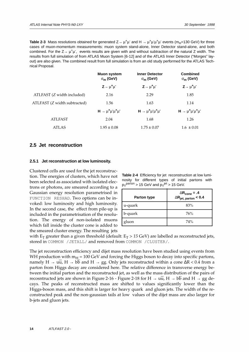
The jet reconstruction efficiency and dijet mass resolution have been studied using events fromWH production with mH = 100 GeV and forcing the Higgs boson to decay into specific partons,namely H → uu, H → bb and H → gg. Only jets reconstructed within a cone ∆R < 0.4 from aparton from Higgs decay are considered here. The relative difference in transverse energy be-tween the initial parton and the reconstructed jet, as well as the mass distribution of the pairs ofrecosntructed jets are shown in Figure 2-16 - Figure 2-18 for H → uu, H → bb and H → gg de-cays. The peaks of reconstructed mass are shifted to values significantly lower than theHiggs-boson mass, and this shift is larger for heavy quark and gluon jets. The width of the re-constructed peak and the non-gaussian tails at low values of the dijet mass are also larger forb-jets and gluon jets.
Table 2-3 Mass resolutions obtained for generated Z→ µ+µ- and H → µ+µ-µ+µ- events (mH=130 GeV) for threecases of muon-momentum measurements: muon system stand-alone, Inner Detector stand-alone, and bothcombined. For the Z→ µ+µ-, events results are given with and without subtraction of the natural Z width. Theresults from full simulation of from ATLAS Muon System [6-12] and of the ATLAS Inner Detector (“Morges” lay-out) are also given. The combined result from full simulation is from an old study performed for the ATLAS Tech-nical Proposal.
Muon systemσm (GeV)
Inner Detectorσm (GeV)
Combinedσm (GeV)
Z→ µ+µ- Z→ µ+µ- Z→ µ+µ-
ATLFAST (Z width included) 2.16 2.29 1.85
ATLFAST (Z width subtracted) 1.56 1.63 1.14
H → µ+µ-µ+µ- H → µ+µ-µ+µ- H → µ+µ-µ+µ-
ATLFAST 2.04 1.68 1.26
ATLAS 1.95 ± 0.08 1.75 ± 0.07 1.6 ± 0.01
Table 2-4 Efficiency for jet reconstruction at low lumi-nosity for different types of initial partons withpT
parton > 15 GeV and pTjet > 15 GeV.
Parton type∆Rcone = .4
∆Rjet, parton < 0.4
u-quark 83%
b-quark 76%
gluon 74%

ATLAS Internal Note PHYS-N0-1XY 30 September 1998
ATLFAST 2.0 - 15
Figure 2-15 Relative difference in pT, ∆pT/pT for initialparton and the reconstructed jet ( ∆Rjet, parton < 0.4)for WH , H→ uu events and for low luminosity(∆Rcone=0.4).
Figure 2-16 Distribution of mjj for reconstructed jetsfrom WH , H→ uu events for low luminosity(∆Rcone = 0.4).
Figure 2-17 Same as Figure 2-15 for WH , H→ bbevents.
Figure 2-18 Same as Figure 2-16 for WH , H→ bbevents.
0
500
1000
1500
2000
-1 -0.5 0 0.5 1
IDMeanRMS
1004 -.1415 .1614
∆pT/pT
0
250
500
750
1000
0 50 100 150 200
15.01 / 3Constant 1062.Mean 90.23Sigma 6.709
mjj (GeV)
0
500
1000
1500
-1 -0.5 0 0.5 1
IDMeanRMS
2004 -.2032 .1862
∆pT/pT
0
200
400
600
0 50 100 150 200
13.17 / 5Constant 685.6Mean 83.99Sigma 8.741
mjj (GeV)

ATLAS Internal Note PHYS-N0-1XY 30 September 1998
16 ATLFAST 2.0 -
2.5.2 Jets labelled as b-jets and c-jets
Of special interest are jets originating from b-quarks (so-called b-jets) which can be identifiedusing b-tagging techniques (vertex or soft-lepton tags). The package labels a jet as a b-jet, if ab-quark of pT > 5 GeV (after FSR) is found in a cone of ∆ R=0.2 around the reconstructed jet forjets with |η| < 2.5. These criteria have been discussed in more detail in [6-9]. These jets are la-belled with KJET(I, 2)=5 . The mass resolution of reconstructed bb pairs is of special inter-est and is shown in Figure 2-21, for events generated through WH production with H → bb andfor mH = 100 GeV. The results are shown in three cases: a) no magnetic field and no smearing, b)magnetic field and no smearing and c) magnetic field and smearing. The dominant mass shiftarises from final state radiation and hadronisation (-12.5 GeV), but a sizeable shift also origi-nates from the magnetic field (-4.9 GeV). As shown by the Gaussian fits in Figures 2-21, the im-pacts of the fragmentation, solenoidal magnetic field and energy smearing are similar andcontribute each ~ 5 GeV to the Gaussian part of the experimental resolution. The fraction ofevents within 82 ± 20 GeV decreases from 86.5% (Figure 2-21 a), to 84% (Figure 2-21 b) and to83% (Figure 2-21 c). After jets energy recalibration (see Chapter 3), the position of the masspeak is shifted to nominal mH mass, and the acceptance in the mass bin mH ± 20 GeV is of 85%.
Jets originating from c-quarks are labelled as c-jets (KJET(I,2)=4 ) if similar criteria are satis-fied.
ATLFAST is not including efficiencies for b-jets tagging. For b-labelled jets efficiencies for tag-ging and inefficiencies for mistagging c-jets and other jets have been parametrised as pT de-pendent functions [6-22] and are available in package ATLFAST-B.
Figure 2-19 The same as Figure 2-15 but for WH ,H→ gg process.
Figure 2-20 The same as Figure 2-16 but for WH ,H→ gg process.
0
500
1000
1500
-1 -0.5 0 0.5 1
IDMeanRMS
3004 -.1379 .1949
∆pT/pT
0
200
400
600
0 50 100 150 200
5.353 / 4Constant 700.9Mean 85.63Sigma 9.271
mjj (GeV)

ATLAS Internal Note PHYS-N0-1XY 30 September 1998
ATLFAST 2.0 - 17
2.5.3 Jets labelled as τ-jets
Of special interest are also jets originating from τ-decay (so called τ-jets), which can be identi-fied in case of hadronic τ−decays. The systematic study of the ATLAS potential for τ-identifica-tion have been documented in ATLAS Technical Proposal [6-13] and was studied afterwardswith new detector layout [6-23]. In case of ATLFAST simulation candidates to be identified as τ-jets are labelled. Required for hadronic τ-decay products is to be relatively hard (default:pT
τ-had > 10 GeV), inside tracking range (|η|<2.5), dominate reconstructed jet (default:pT
τ-had/pTjet > 0.9) and within jet cone (default: ∆Rjet, τ-had < 0.3). The efficiency for τ-labelling
is of 92% for τ-hadronic decays from A→ ττ and for mA = 300 GeV.
ATLFAST is not correcting for efficiencies for τ-jet identification or other jets misidentification.For τ-labelled jets efficiencies for τ-tagging and mistagging have been parametrised [6-23] andare available in package ATLFAST-B.
Figure 2-21 Reconstructed dijet mass mbb distributions for b-labelled jets for no smearing and no B-field, b) nosmearing and with B-field, c) with smearing and with B-field, d) with jet energy recalibration from generated WHevents with H → bb and for mH=100 GeV and for low luminosity performance and default cone algorithm.
0
200
400
600
0 100 200
40.76 / 4Constant 568.5Mean 89.87Sigma 5.704
0
200
400
0 100 200
32.79 / 5Constant 491.4Mean 85.99Sigma 6.778
0
100
200
300
400
0 100 200
11.37 / 6Constant 457.5Mean 84.34Sigma 8.696
0
100
200
300
400
0 100 200
14.35 / 6Constant 446.4Mean 103.8Sigma 11.67
mbb (GeV)
ATLAS Internal Note PHYS-N0-1XY 30 September 1998
18 ATLFAST 2.0 -
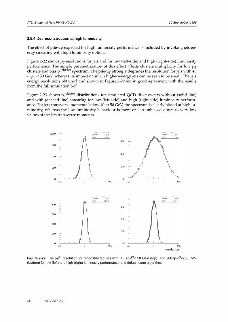
2.5.4 Jet reconstruction at high luminosity
The effect of pile-up expected for high luminosity performance is included by invoking jets en-ergy smearing with high luminosity option.
Figure 2-22 shows pT resolutions for jets and for low (left-side) and high (right-side) luminosityperformance. The simple parametrization of this effect affects clusters multiplicity for low pTclusters and bias pT
cluster spectrum. The pile-up strongly degrades the resolution for jets with 40< pT < 50 GeV, whereas its impact on much higher-energy jets can be seen to be small. The jetsenergy resolutions obtained and shown in Figure 2-22 are in good agreement with the resultsfrom the full simulation[6-5].
Figure 2-23 shows pTcluster distributions for simulated QCD di-jet events without (solid line)
and with (dashed line) smearing for low (left-side) and high (right-side) luminosity perform-ance. For jets transverse momenta below 40 to 50 GeV, the spectrum is clearly biased at high lu-minosity, whereas the low luminosity behaviour is more or less unbiased down to very lowvalues of the jets transverse momenta.
Figure 2-22 The pTjet resolution for reconstructed jets with 40 <pT
jet< 50 GeV (top) and 200<pTjet<250 GeV
(bottom) for low (left) and high (right) luminosity performance and default cone algorithm.
0
500
1000
1500
2000
-0.5 0 0.5
177.1 / 28Constant 1783.Mean -.1249E-02Sigma .6437E-01
0
200
400
600
-0.5 0 0.5
70.21 / 47Constant 654.1Mean .2763E-01Sigma .1874
0
100
200
300
400
-0.5 0 0.5
24.02 / 15Constant 442.8Mean .6128E-02Sigma .4061E-01
0
100
200
300
-0.5 0 0.5
24.20 / 17Constant 351.8Mean .1178E-01Sigma .5171E-01
resolution

ATLAS Internal Note PHYS-N0-1XY 30 September 1998
ATLFAST 2.0 - 19
2.6 Tracks reconstruction
Optionally the tracks reconstruction is provided for charged, stable particles inside Inner Detec-tor coverage (|η|<2.5) and for transverse momenta above threshold( default : pT
particle > 0.5 GeV). Reconstructed tracks parameters (d0, z0, φ, cot(θ), q/pT) aresmeared with parametrization [6-24] as derived from the dedicated studies for Inner DetectorTDR [6-6] and for [6-24] . Smeared and unsmeared tracks parameters are kept in COMMON/TRACKS/ as well as information about the particle code, the position in event common blockand the position and code of up to the 6-the mothers. Available is dedicated parametrizationfor muons, pions (including tails) and electrons (including bremsstrahlung) as well as recon-struction efficiency. All tracks fulfilling kinematical and geometrical criteria are reconstructed,but the corresponding efficiency is also calculated and this information is stored if needed forfurther analysis.
2.7 Missing transverse energy
The missing transverse energy ETmiss is calculated by summing the transverse momenta of
identified isolated photons, electrons and muons, of jets, b-jets and c-jets, of clusters not accept-ed as jets and of non-isolated muons not added to any jet cluster. Finally, the transverse energiesdeposited in cells not used for cluster reconstruction are also included in the total sum. Trans-verse energies deposited in unused cells are smeared with the same energy resolution function
Figure 2-23 The pTjet distribution for reconstructed jets without (solid) and with (dashed) energy smearing
included for low (left-side) and high (right-side) luminosity performance and the default cone algorithm. Respec-tive ratios are shown on bottom plots. Events were filtered on 3 clusters with pT
cluster > 10 GeV (before energysmearing).

ATLAS Internal Note PHYS-N0-1XY 30 September 1998
20 ATLFAST 2.0 -
as for jets, and cells with a deposited transverse energy below a given threshold (default: 0 GeV)are excluded from the sum. In case of high luminosity pile-up is included in cells as its hadronicpart only. From the calculation of this total sum ET
obs the missing transverse energy is obtained,ET
miss = ETobs as well as the missing transverse momentum components, px
miss=-pxobs,
pxmiss=-py
obs. The total calorimeter transverse energy, ∑ ETcalo is calculated as the sum of all the
above transverse energies except that of muons.
Figures 2-24 shows the pTmiss distribution calculated using the above procedure, compared to
the transverse energy distribution of particles escaping detection (muons outside the detectoracceptance and neutrinos) for generated WH events with W → lν and H → bb and for low lumi-nosity performance. Figure 2-25 shows generated (solid) and reconstructed (dashed) W trans-verse mass for W → lν events and simple kinematical selections. The pT
miss resolution,σmiss=σ(px
miss)=σ(pymiss), is given in Table 2-5 as a function of ∑ ET
calo, for three options: withand without magnetic field and energy smearing, and for the case of low luminosity. For low lu-minosity result of σmiss=5.7 GeV is consistent with what is expected from the full simulation ofthe ATLAS detector [6-23]. For high luminosity as ATLFAST is not adding pile-up to cells emptyafter particle energy deposition the result of σmiss=11.3 GeV represents rather the ultimate per-formance of the detector. The (px
miss- pxobs) resolution for di-jet events is shown on Figure 2-26
and Figure 2-27 for low and high luminosity performance. Results are very similar in the A→ττ case, see Figure 2-28 and Figure 2-29.
Figure 2-24 Reconstructed pTmiss -distribution (solid
line) from generated WH events with H → bb and W→ lν . The dashed line shows the transverse energydistribution of particles escaping detection (muonsoutside detector acceptance and neutrinos).
Figure 2-25 The generated (solid) and reconstructed(dashed) W transverse mass from W → lν eventsand after simple kinematical cuts. (CourtesyF. Gianotti )

ATLAS Internal Note PHYS-N0-1XY 30 September 1998
ATLFAST 2.0 - 21
Figure 2-26 The (pxmiss-px
obs) resolution for di-jetevents generated with pT
hard >17 GeV and low lumi-nosity performance.
Figure 2-27 The same as Figure 2-26 but for highluminosity performance.
Figure 2-28 The (pxmiss-px
obs) resolution for A→ ττevents with mA=150 GeV and low luminosity perform-ance.
Figure 2-29 The same as Figure 2-28 but for highluminosity performance.
0
100
200
300
-100 -50 0 50 100
22.59 / 13Constant 270.3Mean .3761E-01Sigma 5.771
resolution
0
50
100
150
-100 -50 0 50 100
21.68 / 19Constant 137.2Mean -.2452Sigma 11.38
resolution
0
1000
2000
-100 -50 0 50 100
147.6 / 14Constant 2621.Mean .1374Sigma 5.999
resolution
0
50
100
150
-100 -50 0 50 100
19.62 / 23Constant 138.6Mean .2938E-01Sigma 11.29
resolution

ATLAS Internal Note PHYS-N0-1XY 30 September 1998
22 ATLFAST 2.0 -
2.8 Trigger selection
A primitive trigger routine to validate selected physics events can be invoked after each eventhas been analysed by the algorithm. This routine is not meant to cover all ATLAS trigger as-pects and levels, but rather to eliminate events which have essentially no chance of passing theATLAS level-1 and level-2 trigger as specified in trigger menu of [6-7]. It is more specificallydedicated to SUSY-particle searches, which will include many complex topologies of type n-jets+ m-leptons + ET
miss. The results from the ATLFAST analysis, i.e. the lists of isolated electrons,photons, isolated and non-isolated muons, and reconstructed jets are used for this trigger selec-tion.
The proposed trigger selection is aimed at:
• compatibility with present LVL1 + LVL2 understanding; complete coverage of possiblesignatures;
• slightly lower thresholds than in the TP for some cases where it might turn out to be jus-tified from the physics and where it is not clearly impossible to implement.
Three classes of trigger particles are used for low and high luminosity performance:
• isolated electrons and photons,
• muons
• jets.
For muons, parametrised trigger efficiency (as studied in [6-12]) is included, see Figure 2-30.Isolated and nonisolated muons are labelled with trigger flag (KEYMUOTRG, KEYMUOXTRG)and only the ones which passed high-pT or low-pT thresholds are considered by the triggermenu given in ATLFAST. For electrons/photons and jets 100% efficiency is assumed for thetime being.
Please note, that for ETmiss calculations all muons, which were classified as isolated or noniso-
lated contribute to visible energy, regardless trigger label.
The details of the default trigger criteria are given in Appendix B.18.
Table 2-5 Reconstructed ETmiss -resolution with and without B-field and/or smearing from generated WH
events with H → bb and W → lν T
WH , H→ bb
Without B-field Without smearing
σm (GeV)
With B-fieldWithout smearing
σm (GeV)
With B-fieldWith smearing
σm (GeV)
25< ∑ ETcalo<50 GeV 2.36 2.57 2.94
50< ∑ ETcalo<100 GeV 2.46 2.68 3.72
100<∑ ETcalo<200 GeV 3.22 3.54 4.89
200<∑ ETcalo<300 GeV 5.41 5.49 6.84
300<∑ ETcalo<400 GeV 6.89 7.52 9.26

ATLAS Internal Note PHYS-N0-1XY 30 September 1998
ATLFAST 2.0 - 23
Figure 2-30 The parametrised efficiency for muon trigger for low, high and low + high pT-thresholds as a func-tion of pT
µ . The barrel and endcap regions are shown separately. Courtesy S. Cetin.
ATLAS Internal Note PHYS-N0-1XY 30 September 1998
24 ATLFAST 2.0 -
2.9 Miscellaneous
2.9.1 Electron/jet and photon/jet separation.
It is not parametrised neither in ATLFAST nor ATLFAST-B. The full simulation results were ob-tained for very particular and in some sense extreme requirements of the detector performance.For jets pΤ of 20 GeV the rejection of 10 000 on the jets reconstructed by ATLFAST can beachieved but at the price of electron efficiency of 70% (estimated from [6-6]). The rejection of5000-7500 could be obtained for jets against photons at the photon identification efficiency of80% (see [6-15]).
For many physics analysis however that high jet rejection is not necessary. As the full simula-tion studies were not performed for such cases it is more informative to rather specify what re-jection is needed to keep the reducible background at the level of 10-20% of signal+bgd forgiven sample than to use some crude number in the fast simulation analysis.
2.9.2 Electron, muon, photon isolation
This issue was not studied with the full simulation. ATLFAST uses a rather crude estimation,asking for Edep < 10 GeV in Rcone = 0.2 and a separation from other jets with Rcone > 0.4.
2.9.3 Electron/photon separation
Not treated by ATLFAST.
For electrons of pT=40 GeV the electron veto efficiency above 99.8% can be achieved while re-taining an efficiency above 96% for photons (not including calorimeter identification criteria)even at high luminosity [6-16].
2.9.4 Charge misidentification
Not treated by ATLFAST.
Electrons are sufficiently delicate that this issue should be studied with full reconstruction . Formuons it is relevant only for very high energies and it is reasonably parametrised by the smear-ing routine for track helix parameters.

ATLAS Internal Note PHYS 10 November 1998
25 ATLFAST 2.0 -
3 More about jets: reconstruction, calibration and tagging
3.1 Comparison to parton-level simulation for b-jets
Parton-level simulation, where selection criteria are applied to quarks and gluons, often leads totoo optimistic results. In [6-9], the parton-level simulation was compared to the particle-levelsimulation (called there jet-level simulation), and large differences were observed for the recon-struction of b-jets and of invariant bb masses and their source was identified. The main points ofthis discussion are recalled below:
• Efficiency for b-jet reconstruction εb-jetrecon.
The probability, that a b-quark produced in the hard scattering process, of pTb-quark >pT
thr leadsto a reconstructed jet with pT
b-jet>pTthr , labelled as a b-jet was studied carefully. This probabili-
ty is close to 100%, if only hard-scattering process (HP) is generated and remains unchanged, ifinitial-state radiation (ISR) is included. However, if final-state radiation (FSR) and hadronisa-tion (HD) are included also, this probability, called subsequently the efficiency for b-jet recon-struction εb-jet
recon, drops 1 to ~ 80% for pTthr>15 GeV and ∆Rcone=0.4 and for the WH , H→ bb
process with mH =100 GeV. This loss in efficiency depends on the b-quark pT- distribution andtherefore depends on the process considered.
• Reconstruction of the invariant mass of two b-jets.
Due to FSR and HD, a large shift in the peak position of the reconstructed mass, mbb, of twob-jets is observed. Additional important effects are the degradation of the mass-resolution andlarge asymmetric tails in the mass distribution (see Figure 2-21). All these effects lead to a signif-icant degradation of the acceptance in a mass window of ± 20 GeV (around the nominal Higgsboson mass), where the size of the mass bin was chosen as that needed in ATLAS. Figure 3-1and Table 3-1, similar to Fig.1 and Table 5 of [6-9], illustrate these effects, as obtained from theATLFAST package, including solenoidal magnetic field. All these effects depend only weaklyon the parameters used for the jet-finding algorithm.
1. The values quoted here are slightly different from these in [6-9], due to the different algorithm used forthe jet reconstruction. More accurate values should always be supplied by the full simulation results.
Table 3-1 Main characteristic of the reconstruction of the H → bb mass peak at particle level, as a function ofthe ingredients used in the event generation, for the WH, H → bb signal at LHC and for mH=100 GeV
Event generation Peak position<m> in GeV
Resolutionσm GeV
Efficiency for m bbwithin < m > ± 20 GeV
HP 99.0 5.0 98.5%
HP + ISR 100.0 6.0 98.5%
HP + ISR + FSR 92.0 9.0 84.0%
HP + ISR + FSR+HD 82.0 9.5 83.0%

ATLAS Internal Note PHYS 10 November 1998
26 ATLFAST 2.0 -
• The effect of the B-field.
Table 3-3 shows the average ratio <pTb-jet/pT
b-quark>, the efficiency for b-jet reconstructionεb-jet
recon and the fitted position of the mass peak <mbb > for WH production with H → bb andmH =100 GeV. Three options with and without B-field and smearing are shown. The magneticfield reduces the efficiency for b-jet reconstruction by 3% and shifts the position of the mbb peakby -5 GeV. The average value <pT
b-jet/pTb-quark> is also reduced by 3% due to the magnetic
field.
Figure 3-1 Reconstruction of the invariant mass distribution of the two b-jets from Higgs boson decay formH = 100 GeV and WH production with H → bb at the LHC, as a function of the ingredients used in the eventgeneration: (a) hard scattering process, (b) initial state radiation, (c) final state radiation and (d) hadronisa-tion/decays.

ATLAS Internal Note PHYS 10 November 1998
ATLFAST 2.0 - 27
3.2 Jet energy calibration (in ATLFAST-B)
The possibility to recalibrate the peak position for the dijet mass has been studied for samples ofu-jets, gluon-jets and b-jets obtained from WH production with respectively H → uu, H → ggand H → bb decays. The jet momenta are recalibrated by a calibration factor Kjet=pT
parton/pTjet
. Here, pTparton denotes the transverse momentum of the parton which initiated the jet (before
FSR). Figure 3-2 shows these calibration factors as a function of pTjet for the three jet flavour ini-
tiators and Figure 3-3 as a function of ∆Rcone. For pTjet >50 GeV, the distributions become as-
ymptotically flat at a value Kjet ~ 1.2 independent of the jet flavour. For pTjet<50 GeV, Kjet is
closer to unity for u-jets than for g-jets and b-jets. The values of Kb-jet and Kg-jet are the samewithin errors over the whole range of pT
cluster.
Table 3-2 Average ratio <pTb-jet/pT
b-quark>, efficiency for b-jet reconstruction εb-jetrecon, and fitted position of the
)mbb peak and acceptance εbin in a mass bin <mbb> ± 20 GeV, for WH production with H → bb and mH=100GeV. The expected results with B-field being on and off are shown without smearing as well as the results withB-field and smearing.
WH , H→ bb Without B-fieldWithout smearing
With B-field Without smearing
With B-field With smearing
<pTb-jet/pT
b-quark> 0.83 0.80 0.80
εb-jetrecon 83% 80% 81%
<mbb> 87.5 GeV 82.6 GeV 82.0 GeV
εbin = 82 ±±± 20 GeV 86.5% 84% 83%
Figure 3-2 Calibration factor, Kjet=pTparton/pT
jet, as afunction of the reconstructed jet transverse momen-tum, pT
jet, for b-jets (solid line), gluon-jets (dashedline) and light-quark jets (dots)
Figure 3-3 Calibration factor, Kb-jet=pTb-quark/pT
b-jet,as a function of the reconstructed jet transversemomentum, pT
b-jet, for jets reconstructed in∆Rcone=0.4 (solid line) and ∆Rcone=0.7.
0
1
2
3
4
0 20 40 60 80 100
pTjet (GeV)
ca
libra
tio
n f
acto
r
0
1
2
3
4
0 20 40 60 80 100
pTjet (GeV)
ca
libra
tio
n f
acto
r

ATLAS Internal Note PHYS 10 November 1998
28 ATLFAST 2.0 -
Figure 3-4 Uncorrected mbb distributions for WH events with H → bb and mH =100 GeV. Shown are the distri-butions for all b-jet pairs (top left), for b-jet pairs not containing any identifiable soft lepton (top right), and for b-jetpairs where both b-jets contain at least one identifiable soft lepton (bottom left). The B-field effects and smearingare included.
Table 3-3 Average ratio <pTb-jet/pT
b-quark>, efficiency for b-jet reconstruction εb-jetrecon, and fitted position of the
mbb peak and acceptance εbin in a mass bin <mbb> ± 20 GeV, for WH production with H → bb and mH=100 GeV.The expected results with B-field being on and off are shown without smearing as well as the results with B-fieldand smearing.
WH , H→ bb Without B-fieldWithout smearing
With B-field Without smearing
With B-field With smearing
<pTb-jet/pT
b-quark> 0.83 0.80 0.80
εb-jetrecon 83% 80% 81%
<mbb> 87.5 GeV 82.6 GeV 82.0 GeV
εbin = 82 ±±± 20 GeV 86.5% 84% 83%
0
500
1000
1500
2000
2500
3000
3500
0 50 100 150 2000
250
500
750
1000
1250
1500
1750
2000
0 50 100 150 200
0
25
50
75
100
125
150
175
200
225
0 50 100 150 200

ATLAS Internal Note PHYS 10 November 1998
ATLFAST 2.0 - 29
In fact, it is well known by now that the prop-erties of b-jets and gluon jets are very similar,whereas they differ noticeably from these ofthe light-quark jets [6-25]. The case of b-jetswas studied further for b-jets containing atleast one identifiable lepton (electron or muonwith pT>1 GeV inside the jet cone), for whichthe calibration factor Kb-jet
lepton was calculatedseparately. Figure 3-5 compares the two cali-bration factors: Kb-jet
aver and Kb-jetlepton. It was
observed that Kb-jetlepton is systematically
higher. This can be qualitatively explained bythe effect of missing neutrino(s) in b-jets withsoft leptons. No strong dependency on the pTof the soft lepton was found for Kb-jet
lepton,however this dependence is visible as a func-tion of the transverse momenta of neutrinos inthe final state. This calibration gives (as shownbellow) proper mass energy scale however isnot giving the proper jet energy scale.Figures 3-4 shows the reconstructed mbb dis-tribution (without calibration) for all b-jetsfor pairs with two non-leptonic b-jets (52% of the sample) and for pairs with two leptonic b-jets(8% of the sample). It can be seen that the pairs of non-leptonic b-jets give a distribution for mbbsimilar to that for pairs of u-jets (compare to Figure 2-15) while the pairs of leptonic b-jets give amuch larger shift in the peak position and width than the average b-jets. Figure 3-6 shows themjj distributions for WH events with H → gg and H → uu. The difference between correctingpT of these jets by using the b-jet calibration factor Kb-jet (left side of Figures 3-6) or by using thecalibration factors, Kg-jet and Ku-jet, determined for each appropriate jet flavour (right side ofFigure 3-6), is noticeably only for H → uu decays. The position of the reconstructed mass peakand the acceptance in the mass window after calibrations using calibration factors Kg-jet andKu-jet or using calibration factor Kb-jet is shown in Table 3-4 .
One should be however aware that the above calibration gives the proper mass energy scale butis not giving proper jet energy scale, as illustrated on Figure 3-7.
The calibration factors can be apply with facilities of the ATLFAST-B package.
Figure 3-5 Calibration factor, Kb-jet=pTb-quark/pT
b-jet,as a function of pT
b-jet, shown separately for b-jetscontaining at least one identifiable soft lepton (solidline) and for all b-jets (dashed line).

ATLAS Internal Note PHYS 10 November 1998
30 ATLFAST 2.0 -
Figure 3-6 Corrected mjj distributions for WH events with mH =100 GeV and H → gg decays (top) and H → uudecays (bottom). The calibration factors applied were those for b-jets (left) and those obtained for gluon jets andu-quark jets respectively (right)
Table 3-4 The fitted peak position <mjj> for generated WH events with H → gg and H → uu decays with andwithout jet calibration by the Kb-jet factor. The acceptance in a given mass window is also shown for the cor-rected sample.
calibration H → gg H → uu
Kb-jet <mbbcalib>
εbin=100 ± 20 GeV 99.2 GeV
78% 99.3 GeV
77%
Ku-jet, Kg-jet <mjjcalib>
εbin=100 ± 20 GeV 101.379%
100.7 GeV86%
Table 3-5 he fitted <mbbcalib > peak position for corrected sample of b-jets and acceptance in the mass window
is given for WH process with H → bb and mH =100 GeV. The option with B-field on/off is shown without smear-ing as well as option with B-field and smearing.
WH , H→ bb no B-field no smearing
with B-field no smearing
with B-fieldwith smearing
<mbbcalib> 102.5 GeV 102.4 GeV 102.4 GeV
εbin= 100 ± 20 GeV 85.6% 85.4% 84.6%

ATLAS Internal Note PHYS 10 November 1998
ATLFAST 2.0 - 31
3.3 Jets reconstruction with Jet Finder library
The Jet Finder library [6-4] which contains different algorithms for clusters reconstruction wasinterfaced to ATLFAST. This provides flexible possibility to combine/cross-check full and fastsimulation analyses. Detailed description on available algorithms and comparison of mass res-olution and calibration coefficients can be found in [6-4]. The JetFinder Library can be activatedwith KEYJF=1 (for KEYJF=0 the default cone algorithm is used). Choice of the required algo-rithm and its parameters have to be specified. For description see [6-4] .
The same version of the jetFinder Library is used also by the full simulation DICE+ATRECONpackage.
Figure 3-7 The pT distribution for hard-process b-quarks (top), reconstructed b-labelled jets (middle) and cali-brated b-labelled jets (bottom) for WH , H→ bb process and low luminosity operation.

ATLAS Internal Note PHYS 10 November 1998
32 ATLFAST 2.0 -
3.4 b-tagging algorithm (in ATLFAST-B)
The fraction of pT of the b-labelled jet carried by the B-hadron is on average ~ 95% for a conesize of ∆ R=0.4. The b-jet itself, however, carries only on average ~80% of the pT of producedb-quark. These numbers illustrate well some of the large differences between parton-level andparticle-level simulations of b-quark reconstruction and of the b-tagging in a real experiment. Inorder to explore the expected Inner Detector environment, when attempting to tag b-jets, the ex-pected numbers of charged particles found within the b-jet cone was studied in [6-9]. It wasshown that a cone size of ∆Rcone=0.4 is sufficient to measure more than 90% of the charged par-ticles from the B-hadron decay. For a realistic threshold of pT
particle > 1 GeV and uncalibratedjets, this cone size includes on average ~ 4.8 charged tracks from B-hadron decay, ~ 2.4 chargedtracks from the b-quark fragmentation and from the underlying event, and a negligible number(<0.2) from minimum bias pile-up at low luminosity. This average (for charged tracks fromB-hadron) increases to ~ 5.2 for b-labelled uncalibrated jets. For calibrated jets it becomes re-spectively ~ 4.5 for any and ~ 5.1 for b-labelled jets.
The much more detailed understanding of the b-tagging performance achieved through thestudies of [6-6] has permitted the implementation of a realistic parametrisation of the b-taggingperformance into the fast simulation used for the study of the signal from WH , H→ bb associ-ated production. This parametrisation has been implemented in the following way [6-22]. Theresults from Section 6.7.6 of [6-6] for mH = 100 GeV have been adapted to account for the differ-ent methods used for labelling jet flavour in the full-simulation studies and in the fast simula-tion program (the latter has to treat many background sources with varying jet multiplicitiesand flavours). ATLFAST is labelling jets as b-jets and c-jets on the criteria that in the distance of∆Rcone=0.2 from the jet axis the heavy flavour quark after FSR with pT > 5 GeV was found. Onthe other hand algorithm which has been used in full simulation for defining the true b-jetbases on the charged track from B-hadron decay of pT> 1GeV found around hard-b quarkwhich initiated a jet [6-6]. In Table 3-7 matching between both algorithms is illustrated.b-quarks from hard process (hard-b), jets and b-labelled jets, without and with energy calibra-tion (cluster were reconstructed down to pT
cluster>10 GeV and after energy smearing accepteddown to pT
jet > 15 GeV) were accepted for pTjet > 15 GeV and B-hadron charged tracks with
pTtrack > 1.0 GeV. Only in 0.3 -0.4 % of cases a jet was labelled as a b-jet in absence of a charged
track from the B-hadron inside the jet cone. However asking for charged track inside the jetcone would give a better acceptance (89.7 % instead of 82.7 %) for the b-labelling of reconstruct-ed jets (80.4 % instead of 75.7 % for non-calibrated jets). The direction of hard-b quark does notalways coincide with the jet direction (as seen already on Figure 2-3 and Figure 2-4) and the effi-ciency for combination jet+track+hard-b to match inside ∆Rcone < 0.4 is of 82.9 % for the conearound jet-axis and of 81.1% for the cone around hard-b. In Table 3-8 these efficiencies are com-pared for calibrated jets and two sizes of ∆Rcone and for b-quark and gluon originated jets.
Table 3-6 The average <ntrack> multiplicity from B-hadrons for different values of ∆Rcone and forpT
track > 1GeV and for WH , H→ bb events.
<ntrack ∆Rcone around hard-b ∆Rcone around jet axis ∆Rcone around b-jet axis
∆Rcone=0.4, uncalibrat. 4.21 4.77 5.18
∆Rcone=0.4, calibrat. 4.21 4.46 5.06
∆Rcone=0.7 calibrat. 4.23 4.45 5.08

ATLAS Internal Note PHYS 10 November 1998
ATLFAST 2.0 - 33
The expected b-tagging performance was parametrised consistently with algorithm for jet-la-belling. Table 3-9 and Table 3-10 shows efficiencies for jets from u, d, s, g (not containingc-quarks nor b-quarks in the final parton shower process) and from charm, respectively and forvertexing alone. The rejections averaged over η and pT are shown in the second column as afunction of the b-tagging efficiency and the other columns show the correction factors appliedto these values to account for the pT-dependence discussed in Section 6.7.6 of [6-6]; These num-
Table 3-7 The matching between hard partons, charged tracks from B-hadrons, jets and b-labelled jets in thecone DR<0.4 for calibrated (uncalibrated ) jets. Normalized to the hard-process b-quark with pT>15 GeV,|h|<2.5. ISR switched off.
generated: WH , H → bb all jets b-labelled jets
∆Rcone around hard-b ∆Rcone around hard-b ∆Rcone around hard-b
1. hard-b 100 %
2. hard-b + track 91.4 %
3. hard-b + jet 83.7 % ( 77.6 % ) 78 % ( 73.4 % )
4. hard-b + jet + track 81.1 % ( 75.7% ) 77.7 % ( 73.0 % )
5. hard-b + jet + no-track 2.4 % ( 1.9 % ) 0.5 % ( 0.4 % )
6. hard-b + no-jet + track 10.3 % ( 15.6 % ) 13.7 % ( 18.3 % )
7. hard-b + no-jet + no-track 6.2 % ( 6.8 % ) 8.1 % ( 8.2 % )
∆Rcone around jet ∆Rcone around jet ∆Rcone around jet
1. jet 99.9 % ( 87.1 % ) 82.7 % ( 76.5 % )
2. jet + track 89.7 % ( 80..0 % ) 82.5 % ( 76.2 % )
3. jet + hard-b 86.2 % ( 79.1 % ) 77.9% ( 73.3 % )
4. jet + hard-b + track 82.9 % ( 76.2 % ) 77.7 % ( 73.0 % )
5. jet + hard-b + no-track 3.8 % ( 2.9 % ) 0.4 % (0.3 %)
6. jet + no hard-b + track 6.0 % ( 3.8 % ) 4.7 % ( 3.2 % )
7. jet + no hard-b + no-track 7.1 % ( 4.2 % ) 0.04% (0.02 %)
Table 3-8 The same as Table 3-7 but for calibrated jets. The matching between calibrated jets, b-labelled jetsand charged tracks from B-hadrons, in cone ∆Rcone<0.4 (in cone ∆Rcone=0.7). Normalized to hard-process par-tons with pT>15 GeV, |η|<2.5. ISR was switched off.
generated: all jets b-labelled jets
WH , H→ bb
1. jet 99.9 % ( 100 % ) 82.7 % ( 84.4 % )
2. jet + track 89.7 % ( 91.4 % ) 82.5 % ( 84.2 % )
WH , H→ gg
1. jet 99.9 % ( 100 % ) 1.4 % ( 1.5 %)
2. jet + track 2.4 % (2.5 %) 1.4 % ( 1.5 %

ATLAS Internal Note PHYS 10 November 1998
34 ATLFAST 2.0 -
bers are implemented in ATLFAST-B package and can be used for randomly tagging on jets la-belled as b-jets, c-jets and other jets.
3.5 τ-tagging algorithm (in ATLFAST-B)
The expected detector performance for identifying hadronic τ−jets was studied extensivelywith full simulation in [6-23]. In ATLFAST the consistent criteria for labelling jets as τ-jets can-didates were incorporated. This parametrization, obtained with the full simulation of A→ ττevents [6-23], specifies pT and |η| dependent jets rejection for required efficiency for τ−jetsidentification and for low luminosity performance. Parametrization is given for three ranges ofpseudorapidity: |η|<0.7, 0.7 < |η| < 1.5 and |η| < 1.5 and for 15 < pT
jet < 150 GeV. OnFigure 3-8 and Figure 3-9 is shown parametrised non-tau jet rejection for fixed tau-tagging effi-ciency.
The tau-veto can be useful for rejection of backgrounds containing taus. A more detailed studyfor tau-veto was done on A to tau-tau events and on the large-jets production events, as pre-sented in [6-23] using cutoffs on electromagnetic radius and number of associated tracks withpT
track>1 GeV. For pTcluster > 60 GeV the εveto,jet=90% with εveto,tau=5% can be achieved. For
pTcluster<60 GeV, with fixed εveto,tau = 5% the εveto,jet < 90% and is decreasing with decreasing
pTcluster. Also for pT
cluster<60 GeV and fixed εveto,jet = 90% the εveto,tau > 5 % and is increasingwith pT
cluster.
The parametrization for τ−tagging efficiency of jets labeled as τ−jets is provided by ATL-FAST-B. This package provides as well parametrisation for the non-tau jet veto.
Table 3-9 For calibrated jets from Higgs-boson decay with mH = 100 GeV not containing any heavy flavourcomponent from charm or bottom, rejections achieved by vertexing alone as a function of the jet pT and of thechosen efficiency for tagging b-jets. Table 6-24 from [6-6].
Jets fromu,d,s,g
Globalrejection
Correction:15< pT<30
Correction:30< pT<45
Correction:45< pT<60
Correction:60< pT<100
Correction:pT > 100
εb = 33% 1400 0.11 0.35 1.80 1.80 1.80
εb = 43% 220 0.28 0.49 2.16 2.16 1.58
εb = 53% 91 0.24 0.51 1.75 2.10 1.95
εb = 64% 32 0.18 0.59 1.50 2.11 1.94
Table 3-10 For calibrated c-jets from Higgs-boson decay with mH = 100 GeV, rejections achieved by vertexingalone as a function of the jet pT and of the chosen efficiency for tagging b-jets. Table 6-25 from [6-6].
Jets fromcharm
Globalrejection
Correction:15< pT<30
Correction:30< pT<45
Correction:45< pT<60
Correction:60< pT<100
Correction:pT > 100
εb = 33% 22.9 0.44 0.68 1.10 1.57 2.17
εb = 43% 10.8 0.58 0.66 1.23 1.59 1.13
εb = 53% 6.7 0.58 0.75 1.40 1.54 1.40
εb = 64% 4.2 0.60 0.82 1.22 1.29 1.28
400±
30±
7±
2±
2.0±
0.6±
0.3±
0.1±

ATLAS Internal Note PHYS 10 November 1998
ATLFAST 2.0 - 35
Figure 3-8 Parametrisation for non-tau jet rejectionfor fixed value of tau-tagging efficiency (from top tobottom) 30%, 50%, 70% and central rapidity range |η|< 0.7.
Figure 3-9 Parametrisation for non-tau jet rejectionfor fixed value of tau-tagging efficiency of 50% and for(from top to bottom) |η|<0.7, 0.7<|η| <1.4 and 1.4 |η| <2.5
1
10
10 2
10 3
10 4
10 5
0 50 100 150
pT (GeV)
1
10
10 2
10 3
10 4
10 5
0 50 100 150
pT (GeV)

ATLAS Internal Note PHYS 10 November 1998
36 ATLFAST 2.0 -

ATLAS Internal Note PHYS 10 November 1998
37 ATLFAST 2.0 -
4 More about tracks helix parameters reconstruction.
Main motivation for including helix parameters reconstruction for charged tracks in the fastsimulation is its possible applicability to the B-physics studies.
For a given set of tracks parameters a smeared set is calculated with a good approximation tothe current best estimate of the Inner Detector performance. Smearing is done according to theparticle type. The three distinguished particle types are: electrons, muons and pions. All othercharged particles are treated as pions.
The detailed description of the parametrisation for tracks resolution and reconstruction efficien-cy can be found in [6-24] . Resolution for muon tracks derived from the full simulation results isconsidered to have no tails within precision aimed for the fast parametrisation. Tracks of elec-trons are smeared initially as for muons but then their tracks parameters are altered by adding aparametrised effect of the bremsstrahlung process. Smearing for pions is described by the sumof two Gaussian contributions representing the core and the tail.
The tracks finding efficiency is also parametrised. All tracks which pass kinematical and geo-metrical selection are reconstructed with 100% efficiency by the ATLFAST but the expected re-construction efficiency is however calculated and stored in the ntuple together with the tracksparameters.

ATLAS Internal Note PHYS 10 November 1998
38 ATLFAST 2.0 -
Figure 4-1 Normalised resolution for helix parameters and reconstruction track efficiency for muons.(WH, H → bb sample was generated).

ATLAS Internal Note PHYS 10 November 1998
ATLFAST 2.0 - 39
Figure 4-2 Normalised resolution for helix parameters and reconstruction track efficiency for elec-trons. (WH, H → bb sample was generated)

ATLAS Internal Note PHYS 10 November 1998
40 ATLFAST 2.0 -
Figure 4-3 Normalised resolution for helix parameters and reconstruction track efficiency for pions.(WH, H → bb sample was generated)

ATLAS Internal Note PHYS 10 November 1998
41 ATLFAST 2.0 -
5 Outlook
This second version of a somewhat elaborate particle-level simulation program, which incorpo-rates most of the ATLAS detector global performance parameters, can be used for many studies,where the details of the ATLAS detector performance (non-Gaussian tails, cracks, etc...) are notof crucial importance. Till now it has been used for many physics studies performed insidePhysics Working Groups of ATLAS Collaboration. Hopefully in the present version this pack-age inadequate for many studies foreseen with the fast simulation for the Overall PerformancePhysics TDR.
The ATLFAST can be used as "stand-alone" but is also implemented into the ATGEN package[6-29] with the aim to have a complete tool for physics studies at the particle level abnd intothe Combined Ntuple framework (CBNT) [6-32]of ATLAS reconstruction packages.
6 Reference
6-1 E. Richter-Was, D. Froidevaux and L. Poggioli, ATLAS Internal Note, PHYS-No-079(1996)
6-2 E. Richter-Was, D. Froidevaux, F. Gianotti, L. Poggioli, D. Cavalli and S. Resconi ,ATLAS Internal Note, PHYS-No-074 (1996).
6-3 ATLAS presentation on LHCC SUSY workshop, CERN, October 1996.
6-4 M. Bosman, I.C. Park , M. Cobal, D. Costanzo, S. Lami, R. Paoletti, G. Azuelos, K. Strahl,ATLAS Internal Note, ATL-SOFT-98-038 (1998) ;
6-5 ATLAS Collaboration, Calorimeter Performance Technical Design Report,CERN/LHCC/97-1, 15 January 1997.
6-6 ATLAS Collaboration, Inner Detector Technical Design Report, CERN/LHCC/97-16,ATLAS TDR 4, 30 April 1997.
6-7 ATLAS Collaboration, ATLAS Trigger Performance Status Report, CERN/LHCC/98-15,30 June 1998.
6-8 A. DellAcqua et al, ATLAS Internal Note PHYS-No-102 (30 July 1997).
6-9 D. Froidevaux, E. Richter-Was, ATLAS Internal Note, PHYS-No-043 (1994);
6-10 D. Cavalli and S. Resconi, ATLAS Internal Note PHYS-No-100 (1996)
6-11 P. Savard and G. Azuelos, ATLAS Internal Note, ATL-PHYS-98-128 (1998).
6-12 ATLAS Collaboration Muon Spectrometer Technical Design Report,CERN/LHCC/97-22, ATLAS TDR 10, 31 May 1997.
6-13 ATLAS Technical Proposal, CERN/LHCC/94-43, 15 December 1994.
6-14 D. Froidevaux and E. Richter-Was, The H → γγ channel in association with high ET/E jets,unpublished;
6-15 E. Richter-Was, D. Froidevaux, F. Gianotti, L. Poggioli, D. Cavalli and S. Resconi ,ATLAS Internal Note, PHYS-No-048 (1995).F. Gianotti and I. Vichou, ATLAS Internal Note PHYS-No-78 (1996).
6-16 D. Rousseau, ATLAS Internal Note , INDET-N0-198, Phys-N0-119 (1998)
6-17 L. Poggioli, ATLAS physics meeting, Trest, 1995.

ATLAS Internal Note PHYS 10 November 1998
42 ATLFAST 2.0 -
6-18 O. Linossier and L. Poggioli, ATLAS Internal Note, PHYS-No-075 (1995) andPHYS-No-101 (1997).
6-19 C. Guyot, private communication, July 1997.
6-20 M.Virchaux and L.Chevalier, private communication, July 1997.
6-21 L. Poggioli, D. Froidevaux and C. Guyot, ATLAS Internal Note, Phys-No-076 (1995).
6-22 E. Ross private commun. and [6-6].
6-23 D. Cavalli and S. Resconi, ATLAS Internal Note , ATLAS Phys-No-118 (1998).
6-24 E.J.Buis, R. Dankers, S. Haywood, A. Reichold. ATLAS Internal Note, INDET-No-195,December 1997; E.J.Buis, R. Dankers, A. Reichold, S. Haywood, F.G. Tartarelli, and N.labanca, ATLAS Internal Note, ATL-INDET-98-215 (1998).
6-25 OPAL Collaboration, CERN preprint CERN-PPE/95-126.
6-26 See transparencies from ATLAS Physics Workshop on SUSY Particles, Stockholm 18-19January 1996 (Sweden).
6-27 T. Sjostrand, “High-Energy-Physics Event Generation with PYTHIA 5.7 and JETSET 7.4”,CERN preprint CERN-TH.7111/93 and CERN-TH.7112/93.
6-28 G. Marchesini et al., Comput. Phys. Commun. 67 (1992) 465.
6-29 A. Amorim, “ATGEN-Monte Carlo interface using GENZ”, ATLAS Internal Note,SOFT-No-010 (1995).
6-30 F. E. Paige and S. D. Protopopescu, Manual ISAJET 7.13.
6-31 The demonstration deck was preapared and tested by S. Klyukhin, email:[email protected]
6-32 D. Rousseau, Combined Ntuple from ATLAS reconstruction packages,http://atlasinfo.cern.ch/Atlas/GROUPS/PHYSICS/physics.html

ATLAS Internal Note PHYS 10 November 1998
ATLFAST 2.0 - 43
A General comments about ATLFAST and ATLFAST-B
The simulation algorithm is run by a call to the routineATLFAST.
The analysed events should be stored in COMMON /ATLFEVENT/. INTEGER N, K Event content
REAL P, V COMMON/ATLFEVENT/N,K(10000,5),P(10000,5),V(10000,5)
The conventions for the particle status, mother-daughter relations, particle codes etc. as in commonblock /LUJETS/ from PYTHIA generator should be assured by the user. Please, follow the manual[6-27]. Vertex position should be given in mm!.
The input/output logical identifiers should be defined in COMMON /ATLNOUT/
INTEGER ATLNINP, ATLNOUT Input/output
COMMON/ATLNOUT/ ATLNINP, ATLNOUT
The package uses one input data file, which contains the parameters for event analysis and trig-gering.
A.1 Subroutine ATLFAST
This is the main routine called by the user to run the ATLFAST package. The following modesare implemented:
• MODE=-1 — initialising, which should be called before the first event is analysed;
• MODE= 0 — simulating, which should be called event by event;
• MODE= 1 — closing, which should be called after the last event has been analysed.
• also it is possible to invoke additional modes for special purposes:
• MODE=2 — simulating event with a second set of values of the jet-cone reconstruction.In this case the algorithm is repeated and ATLFAST common blocks are overwritten;
This routine calls other routines: MAKIOU, MAKFMT, MAKINF, MAKINI , MAKDMP, MAKCLU,MAKELE, MAKMUO, MAKPHO, MAKJET, MAKBJE, MAKCJE, MAKTAU, MAKTRA, MAKMIS,MAKMSC, MAKTRG, MAKUSE.
A.2 Interface to event generators
The information on the simulated event is based on particle COMMON /ATLFEVENT/with theconventions for particle codes and inheritance as in the PYTHIA [6-27] generator. Theexamples of using PYTHIA, HERWIG[6-28], and ISAJET [6-30] as generators for simulatedevents are prepared as well as an example of reading events from GENZ tape [6-26]. ATLFASTis also interfaced to the ATGEN package [6-29] for ATLAS event generation and to the Com-bined Ntuple (CBNT) [6-32] from ATLAS recosntruction packages.

ATLAS Internal Note PHYS 10 November 1998
44 ATLFAST 2.0 -
A.3 Structure of the output from ATLFAST
The output of the algorithm consists of lists arranged in order of decreasing pT, of selected iso-lated electrons COMMON /ISOELE/, isolated muons COMMON /ISOMUO/, non-isolated muonsCOMMON /NOISOMUO/, isolated photons COMMON /ISOPHO/, of reconstructed jets COMMON/JETALL/ , and of the reconstructed pT
miss COMMON /PTMISS/. Each event is passed through aprimitive trigger routine and the logical output from this routine is contained in the COMMON/TRIGER/ . For specific studies one can also use the COMMON /CLUSTER/, where all hadronicclusters are kept, and the COMMON /CELLS/, which contains all cell-energy depositions.
In addition, some standard histograms are also filled, to give more information about the ana-lysed sample. These histograms monitor multiplicity of isolated leptons, photons and jet multi-plicities, the average shifts in E, pT, η and φ due to energy smearing, the mass distributions forlepton and jet pairs, etc. Another set of histograms keeps track of the differences between par-ton-level and particle-level analyses, by monitoring the kinematical variables of the originalpartons. These histograms should however be treated with some caution, since some of themare only correctly filled for certain physics processes, or certain option of the event generation.
SUBROUTINE ATLFNTUP (in file atlfastntup.f) can be used for ntuples storage.
A.4 User analysis with ATLFAST
The algorithm invokes the dummy routine SUBROUTINE MAKUSEwhere the user analysis canbe implemented. This routine is called by the algorithm in the initialization, running and clos-ing mode. In the running mode, it is called after each event is analysed by the algorithm.
A.5 User analysis with ATLFAST-B
This set of routines is meant to facilitate user analysis of events simulated with ATLFAST andalso provides parametrization for jet recalibration and b-tagging and τ-tagging efficiencies.Event stored in CWNtuple (SUBROUTINE ATLFNTUP in atlfastntup.f file) can be processedthrough the chain of routines ATLFEVE, ATLFPHO, ATLFLEP, ATLFBJE, ATLFTAU,ATLFTRG (ATFPHO, ATLFLEP still dummy) in atlfast-b.f file to complete the simulation byATLFAST of randomly applied efficiencies for tagging and identification. The output structure(incorporated in common blocks) is very similar to the ATLFAST one and provides the userwith CRUDE (after ATLFAST) and DETECTED (after ATLFAST + ATLFAST-B) events. In SUB-ROUTINE ATLFASTB, in loops over already existing ntuple, the user should build sequence ofcalls to ATLFXXX routines specific to his analysis (e.g. there is no point to identify τ-jets if theyare of no interest) and supply the ATLFUSEroutine which provides crude and detected events.
A.6 Structure of the distributed version
ATLFAST is written in FORTRAN77, and its source code is splitted into several files andthe input data are in one data file (for ATLFAST steering) and dedicated data files for muonresolution calculations, tracks parameter smearing and jetfider library. The distributed ver-

ATLAS Internal Note PHYS 10 November 1998
ATLFAST 2.0 - 45
sion contains a set of UNIX subdirectories:
• lib - contains main source code of ATLFAST in files:atlfast.f , atlfastmuo.f atl-fastind.f atlfastmsc.f atlfastntup.f and subdirectories: lib/id_atlfast, lib/jet_atlfastand lib/mu_atlfast
• data - contains the input parameters set-up by the user in one single fileatlfast.dat andas well as subdirectories with data files for JetFinder Library and used by smearing pro-cedures:mu_dat, id_dat, jet_dat.
• demo-pythia57, demo-pythia61, demo-pythia6103-isasusy- are a demonstration direc-tories for running with the PYTHIA generator
• demo-isajet - is a demonstration directory for running with the ISAJET generator
• demo-herwig - is a demonstration directory for running with the HERWIG generator
• demo-genz- is a demonstration directory for running with events stored on GENZ formattapes.
• demo-atlfast-b- contains source code ofATLFAST-B in one single fileatlfast-b.f andand example how to use it.
Directory atlfast-rw-r----- 1 erichter zzmn 553287 Aut 7 14:57 NOTE-ATLFAST-2.0.psdrwxr-x--- 2 erichter zzmn 1024 Aut 7 13:40 datadrwxr-x--- 2 erichter zzmn 1024 Aut 7 15:39 demo-atlfast-bdrwxr-x--- 2 erichter zzmn 1024 Aut 7 15:39 demo-genzdrwxr-x--- 3 erichter zzmn 1024 Aut 7 14:57 demo-isajetdrwxr-x--- 3 erichter zzmn 1024 Aut 8 09:11 demo-herwigdrwxr-x--- 3 erichter zzmn 1024 Aut 8 09:11 demo-pythia57drwxr-x--- 3 erichter zzmn 1024 Aut 8 09:11 demo-pythia61drwxr-xr-x 6 erichter zp 2048 Jul 29 16:10 demo-pythia6103-isasusydrwxr-x--- 2 erichter zzmn 1024 Aut 8 08:58 lib-rw-r----- 1 erichter zzmn 192 Aut 6 17:33 makefile
Directory atlfast/lib-rw-r----- 1 erichter zzmn 132569 Aut 8 08:58 atlfast.f-rw-r----- 1 erichter zzmn 132569 Aut 8 08:58 atlfastind.f-rw-r----- 1 erichter zzmn 132569 Aut 8 08:58 atlfastmsc.f-rw-r----- 1 erichter zzmn 132569 Aut 8 08:58 atlfastmuo.f-rw-r----- 1 erichter zzmn 132569 Aut 8 08:58 atlfastntup.fdrwxr-xr-x 6 erichter zp 2048 Jul 31 06:18 id_atlfastdrwxr-xr-x 2 erichter zp 2048 Jul 29 12:36 jet_atlfast-rw-r--r-- 1 erichter zp 573948 Aug 4 15:43 libatlfast.adrwxr-xr-x 2 erichter zp 2048 Jul 29 12:33 mu_atlfast-rw-r----- 1 erichter zzmn 383 Aut 8 09:51 makefile
Directory atlfast/data-rw-r--r-- 1 erichter zp 6395 Mar 1 19:19 atlfast.datlrwxr-xr-x 1 erichter zp 22 Mar 7 14:55 id_datalrwxr-xr-x 1 erichter zp 22 Mar 7 14:55 jetdatalrwxr-xr-x 1 erichter zp 22 Mar 7 14:55 mu_data

ATLAS Internal Note PHYS 10 November 1998
46 ATLFAST 2.0 -
Each subdirectory is equipped with a makefile. The user can thus execute the commands makeand make run issued from the demo-... subdirectories. The first command compiles the pro-gram and the latter executes with an example data file.
A.6.1 demo-pythia57
This directory contains a demonstration program demo.f. This program generates a sample ofevents using the PYTHIA generator and analyses them using ATLFAST. The input data are readfrom the file atlfast.dat in subdirectory data and the outputs of the program are written to thesubdirectory demo-pythia/prod in the file demo.out and the stored histograms and ntuple inthe file demo.hbook and ntuple in the file atlfast.ntup.
In this demonstration program, the generation of the following hard processes can be invokedby changing in the demo.f code the value of the parameter KEYPRO:KEYPRO= 1 — H → γγ, mH =100 GeVKEYPRO= 2 — Z → e+e− ,KEYPRO= 3 — Z→ µ+µ-,KEYPRO= 4 — H → ZZ∗ → 4e , mH=130 GeVKEYPRO= 5 — H → e+e−µ+µ− , mH =130 GeVKEYPRO= 6 — H → µ+µ-µ+µ- , mH =130 GeVKEYPRO= 7 — WH , H→ bb, W → lν, mH =100 GeVKEYPRO= 8 — WH, H → gg, mH =100 GeVKEYPRO= 9 — WH, H → uu, W → lν, mH =100 GeVKEYPRO=10 — bbA, A→ ττ, mA=300 GeV
The user can also easily select various options for the event generation by changing the parame-ter KEYHAD in the code of demo.f:KEYHAD=0 — HP,KEYHAD=1 — HP + ISR,KEYHAD=2 — HP + ISR + FSR,KEYHAD=3 — HP + ISR + FSR + HD (default),KEYHAD=4 — HP + ISR + HD,KEYHAD=5 — HP + FSR + HD,
Directoryatlfast/demo-pythia57
-rw-r----- 1 erichter zzmn 13564 Aut 8 09:11 demo.f-rw-r----- 1 erichter zzmn 746 Aut 1 11:06 makefiledrwxr-x--- 2 erichter zzmn 1024 Aut 8 08:56 prod
Directory atlfast/demo-pythia57/prod-rw-r--r-- 1 erichter zzmn 5143360 Aut 7 15:43 atlfast.ntup-r--r----- 1 erichter zzmn 75 Aut 7 15:43 core-rw-r--r-- 1 erichter zzmn 143360 Aut 7 15:43 data--> ../../data-rw-r--r-- 1 erichter zzmn 143360 Aut 7 15:43 demo.hbook-rw-r--r-- 1 erichter zzmn 221835 Aut 6 17:20 demo.out-rw-r----- 1 erichter zzmn 64 Aut 6 17:20 go

ATLAS Internal Note PHYS 10 November 1998
ATLFAST 2.0 - 47
A.6.2 demo-herwig
This directory contains a demonstration program for generation with HERWIG. The main pro-gram is herwgen.f. There is a makefile for building an executable. First the pointers to exter-nal libraries and datafiles on your favourite computer need to be defined in the makefile. Thedistribution should include:
-rw-r--r-- 1 jesper zp 2173 Nov 19 16:49 README.txt
-rwxr--r-- 1 jesper zp 45 Nov 19 12:19 go
-rw-r--r-- 1 jesper zp 7894 Nov 17 18:42 herwgen.f
-rw-r--r-- 1 jesper zp 127303 Nov 17 16:06 hwudat.f
-rw-r--r-- 1 jesper zp 1954 Nov 19 12:20 makefile
-rw-r--r-- 1 jesper zp 338 Nov 19 11:09 test.datacard
To compile type make and to install type make install. To cleanup and remove all directories domake superclean if you need to reinstall. The directories created and their contents are (afteryou have executed the makefile).
./prod
drwxr-xr-x 2 jesper zp 2048 Nov 21 16:03 data
-rwxr--r-- 1 jesper zp 45 Nov 21 16:03 go
lrwxr-xr-x 1 jesper zp 15 Nov 21 16:03 herw.par -> ./test.datacard
-rwxr-xr-x 1 jesper zp 3121632 Nov 21 16:04 herwgen.x
-rw-r--r-- 1 jesper zp 338 Nov 21 16:03 test.datacard
./prod/data/atlfast.dat -- the ATLFAST data files copied from atlfast/data
Parameters are set in the test.datacard file that either needs to be linked or copied to herw.parwhich is the file that herwgen.x reads. After installation herw.par is linked to test.datacard. Thefollowing HERWIG parameters are read from the datacard file herw.par: IPROC, MAXEV,IPRINT, MAXPR, NRN(1), NRN(2), PTMIN, PTMAX, NSTRU. The colliding beams and theirmomenta are hardwired in herwgen.f. All other HERWIG parameters are set to their defaultvalue. Consult the HERWIG manual. All parameters can in principle be set in the datacard file,but then you need to include those parameters in SUBROUTINE HERWCARD, which is us-ing the FFREAD package. (If you do so note that HERWIG real variables are defined to be dou-ble precision).
HERWIG stores the particles in HEPEVT format. It is converted with calls to the following rou-tines:
HERW2LU -- converts HEPEVT to LUJET format (included in herwgen.f)
ATLPYTHIA57 -- converts LUJET to ATLFEVENT format (part of ATLFAST distribution, butis included in herwgen.f)

ATLAS Internal Note PHYS 10 November 1998
48 ATLFAST 2.0 -
The output files of the sample job are written to the prod directory.
The file fort.88 is the Sudakov table generated by HERWIG (see manual).
To run:
Go to directory prod and:
herwgen.x > test.log& or use script go
--> the normal atlfast output is written to this directory
To remove atlfast output one can use: make cleanprod
A.6.3 demo-isajet
This directory contains a demonstration program for generation with ISAJET. The main pro-gram is isagene.f. There is a makefile for building an executable. First the pointers to externallibraries and datafiles on your favourite computer need to be defined in the makefile. The distri-bution include:
-rw-r----- 1 jesper zp 2127 Nov 19 22:19 README.txt
-rwxr--r-- 1 jesper zp 47 Nov 19 12:23 go
-rw-r--r-- 1 jesper zp 4837 Nov 20 09:20 isagene.f
-rw-r--r-- 1 jesper zp 2194 Nov 19 14:35 makefile
-rw-r--r-- 1 jesper zp 169 Nov 20 08:57 test.datacard
To compile type make and to install type make install.
To cleanup and remove all directories do make superclean if you need
to reinstall. The directories created and their contents are
(after you have executed the make install):
/prod/
drwxr-xr-x 2 jesper zp 2048 Nov 21 16:08 data
-rwxr--r-- 1 jesper zp 47 Nov 21 16:08 go
drwxr-xr-x 2 jesper zp 2048 Nov 21 16:08 isadata
-rwxr-xr-x 1 jesper zp 12007448 Nov 21 16:09 isagene.x
lrwxr-xr-x 1 jesper zp 15 Nov 21 16:08 isajet.par -> ./test.datacard
-rw-r--r-- 1 jesper zp 169 Nov 21 16:08 test.datacard
/prod/data/atlfast.dat -- atlfast settings
You need change the LSP code to be 67
./prod/isadata/isadecay.dat -- the ISAJET decaytable

ATLAS Internal Note PHYS 10 November 1998
ATLFAST 2.0 - 49
All parameters for ISAJET generation are read from the datacard file isajet.par. All parameterscan be set in the datacard file. For the parameter descriptions consult the ISAJET manual. TheLSP particle code need to be set in the atlfast.dat - SPYTHIA uses particle code 66 for the LSPand ISAJET particle code 67. Before generation copy or link your datacard file to isajet.par. Af-ter installation isajet.par is linked to test.datacard
The output files for the sample job will be written to the prod directory.
ISAJET stores the particles in its own event format. It is converted with calls to the followingroutines:
ISAHEP(1) -- converts from ISAJET to HEPEVT format (part of ISAJET distribution)
HEP2LU -- converts HEPEVT to LUJET format (included in isagene.f)
ATLPYTHIA57 -- converts LUJET to ATLFEVENT format (part of ATLFAST distribution, but isincluded in isagene.f)
The output files of the sample job are written to the prod directory.
To run:
Go to directory prod and:
herwgen.x > test.log& or use script go
--> the normal atlfast output is written to this directory
To remove atlfast output one can use: make cleanprod
A.6.4 demo-genz
This directory contains a demonstration program demo.f, which simulates events stored ontothe tape in GENZ format. The event is read form the file ZEBRA.P (the modified version of rou-tines READJOBand GNZOPENby R. DeWolf are used), stored in the COMMON /ATLFEVE/andanalysed by ATLFAST algorithm. The input data are read from the file atlfast.dat in subdirecto-ry data and the outputs of the program are written to the subdirectory demo-genz/prod in a filedemo.out and ntuple in a file atlfast.ntup.
Directory atlfast/demo-genz lrwxr-xr-x 1 erichter zp 39 Aut 4 14:30 ZEBRA.P ->.....
-rw-r--r-- 1 erichter zp 13265 Aut 4 15:49 demo.f -rw-r----- 1 erichter zp 268764 Aut 8 12:11 libgenz.a -rw-r----- 1 erichter zp 831 Aut 4 15:58 makefile drwxr-x--- 2 erichter zp 2048 Aut 4 15:56 prod
The user should however check if the COMMON /ATLFEVENT/is correctly filled (correct statusof particles and particle code) if the event stored on tape were generated by generator otherthen PYTHIA generator.

ATLAS Internal Note PHYS 10 November 1998
50 ATLFAST 2.0 -
A.6.5 demo-atlfast-b
This directory contains the source code of ATLFAST-B in atlfast-b.f file, the histograms used forjets recalibration in atlf_calibration.hbook, and in atlf_analiza.kumac with example of analy-sis done with ATLFAST-B on ntuple atlfast.ntup with simulated WH , H→ bb events . Theatlf_histos.kumac defines histograms and atlf_nice.kumac gives nice graphics. Theatlf_analiza.hbook contains stored histograms of the results of analysis.
The main ingredients of atlfast-b.f are routines: ATLFCAL, ATLFBJE, ATLFTAU for jets ener-gy calibration, b-tagging and τ-tagging simulations.
Directory atlfast/demo-atlfast-b
drwxr-xr-x 2 erichter zp 2048 Aug 1 16:47 .drwxr-x--- 10 erichter zp 2048 Jul 22 14:41 ..-rw-r--r-- 1 erichter zp 16384 Jul 22 11:15 atlf_anal.hbook-rw-r----- 1 erichter zp 14265 Aug 1 16:47 atlf_analiza.f-rw-r----- 1 erichter zp 282 Jul 22 11:01 atlf_analiza.kumac-rw-r--r-- 1 erichter zp 16384 Jul 18 16:41 atlf_calibration.hbook-rw-r----- 1 erichter zp 471 Jul 22 11:14 atlf_histos.kumac-rw-r----- 1 erichter zp 287 Jul 18 18:07 atlf_nice.kumac-rw-r--r-- 1 erichter zp 4411392 Jul 18 16:27 atlfast.ntup

ATLAS Internal Note PHYS 10 November 1998
51 ATLFAST 2.0 -
B Subroutines in the ATLFAST package
B.1 Subroutine MAKUSE
The dummy user routine for the event analysis.
B.2 Subroutine MAKIOU
This routine defines the input/output logical identifies for the ATLFAST package. It transfersthem from COMMON /ATLNOUT/ to COMMON /MAKNOUT/.
B.3 Subroutine MAKFMT
This routine defines nice and flexible formats for printing outputs. These formats are stored inthe COMMON /BX/ and COMMON /DX/.
B.4 Subroutine MAKINF
This routine prints out information about the package version.
B.5 Subroutine MAKDMP
This routine prints out the contents of output commons.
B.6 Subroutine MAKINI
This routine reads from the input data file the values of all parameters which can be set by theuser and which are subsequently used for the event analysis. These parameters are sent to otherroutines via the arrays LPAR (99) , YPAR(999) and TPAR(99,2) . The lists of these parame-ters and of their default values are given in Table B-1 and Table B-2 .
Table B-1 List of parameters read by the SUBROUTINE MAKINI from atlfast.dat. Parameters for the event anal-ysis. The default values are quoted in front of each parameter’s name and definition.
------ Flags and switches ---------------
1 --- LPAR(1) ....Id for histograms
1 --- LPAR(2) ....Luminosity option low=1, high=2
1 --- LPAR(3) ....B-field on=1, off=0

ATLAS Internal Note PHYS 10 November 1998
52 ATLFAST 2.0 -
1 --- LPAR(4) ....Smearing on=1, off=0
3 --- LPAR(5) ....Smear for muons: muon=1, track=2, combin=3
2 --- LPAR(15) ....Smear for muons: exact=1, approxim =2
66 --- LPAR(6) ....Code for SUSY LSP particle
10 --- LPAR(7) ....Number of events to be printed
0 --- LPAR(11) ....track/finding on=1, off=0
011 --- LPAR(12) ....ID config.: 011=B-layer, no vertex constr, uniform B-field
2 --- LPAR(112) ....ID reconstr cuts: 1=btag cuts; 2=btag+TR cuts
0 --- LPAR(13) ....JetFinder switch: 0= cone algorithm; 1=JetFinder algorithms
0 --- LPAR(14) ....muon trigger labelling: off=0, on=1
C------ Parameters for MAKCLU ---------------
10.000 --- YPAR(10) ....Minimum E_T for calo cluster
0.400 --- YPAR(11) ....Cone Delta R for barrel set 1
0.400 --- YPAR(16 ) ....Cone Delta R for forward set 1
0.700 --- YPAR(111) ....Cone Delta R for barrel set 2
0.700 --- YPAR(116) ....Cone Delta R for forward set 2
5.000 --- YPAR(12) ....Rapidity coverage for calorimeter
1.500 --- YPAR(13) ....Min E_T for cluster initiator
0.500 --- YPAR(14) ....Min p_T for B-field
0.000 --- YPAR(15) ....Min E_T for cell
3.000 --- YPAR(17) ....Barrel/fwd transition in eta in CALO
0.100 --- YPAR(18) ....Granularity in eta (barrel), 2x in fwd
0.100 --- YPAR(19) ....Granularity in phi (barrel), 2x in fwd
0 --- LPAR(10) ....Cells energy sharing in clusters on/off
C------ Parameters for MAKMUO ---------------
6.000 --- YPAR(20) ....Minimum muon momentum
2.500 --- YPAR(21) ....Maximum muon eta
0.400 --- YPAR(27) ....Min cone R separation from clusters for muon isol.
0.200 --- YPAR(28) ....Delta R cone for energy deposition
10.000 --- YPAR(29) ....Max energy deposition for isolation
C------ Parameters for MAKPHO ---------------
5.000 --- YPAR(30) ....Minimum photon momentum
2.500 --- YPAR(31) ....Maximum photon eta
Table B-1 List of parameters read by the SUBROUTINE MAKINI from atlfast.dat. Parameters for the event anal-ysis. The default values are quoted in front of each parameter’s name and definition.

ATLAS Internal Note PHYS 10 November 1998
ATLFAST 2.0 - 53
0.100 --- YPAR(35) ....Delta R for photon matching to cluster
0.400 --- YPAR(37) ....Min cone R separation from clusters for photon isolation
0.200 --- YPAR(38) ....R_cone for energy deposition
10.000 --- YPAR(39) ....Max energy deposition for isolation
C------ Parameters for MAKELE ---------------
5.000 --- YPAR(40) ....Minimum electron momenta
2.500 --- YPAR(41) ....Maximum electron eta
0.100 --- YPAR(45) ....Delta R for electron matching to cluster
0.400 --- YPAR(47) ....Min cone R separation from clusters for electron isolation
0.200 --- YPAR(48) ....R_cone for energy deposition
10.000 --- YPAR(49) ....Max energy deposition for isolation
C------ Parameters for MAKJET ---------------
15.000 --- YPAR(51) ....Minimum E_T for jet
5.000 --- YPAR(52) ....Rapidity coverage for jets
C------ Parameters for MAKBJE ---------------
5.000 --- YPAR(60) ....Minimum b-quark p_T(after FSR) for b-jet matching
2.500 --- YPAR(61) ....Maximum b-quark eta for b-jet matching
0.200 --- YPAR(62) ....Delta R for b-jet matching to b-quark
C------ Parameters for MAKCJE ---------------
5.000 --- YPAR(70) ....Minimum c-quark p_T(after FSR) for c-jet matching
2.500 --- YPAR(71) ....Maximum c-quark eta for c-jet matching
0.200 --- YPAR(72) ....Delta R for c-jet matching to c-quark
C------ Parameters for MAKMIS ---------------
0.000 --- YPAR(80) ....Minimum E_T for unused cells
C------ parameters for MAKTAU ---------------
10.000 --- YPAR(90) ....minimum tau-had pt for tau-jet label
2.500 --- YPAR(91) ....maximum tau-eta for tau-jet label
0.300 --- YPAR(92) ....max R_tauj for tau-jet
0.900 --- YPAR(93) ....min ratio for tau-hadron/jet momentum
C------ parameters for MAKTRA ---------------
0.500 --- YPAR(100) ....minimum pt for track
2.500 --- YPAR(101) ....maximum eta for track
Table B-1 List of parameters read by the SUBROUTINE MAKINI from atlfast.dat. Parameters for the event anal-ysis. The default values are quoted in front of each parameter’s name and definition.

ATLAS Internal Note PHYS 10 November 1998
54 ATLFAST 2.0 -
Table B-2 CList of parameters read by SUBROUTINE MAKINI from atlfast.dat. Parameters for the event trigger.The default values are quoted in front of each parameters name and definition.
C------ parameters for MAKTRG ---------------
C ........ isolated electron/photon trigger............
2.5 --- TPAR( 9,1) ... eta-coverage for electrons/photons
20.0 --- TPAR( 1,1) ... Minimum p_T for 1 electron low lumi
30.0 --- TPAR( 1,2) ... high lumi
40.0 --- TPAR( 2,1) ... Minimum p_T for 1 photon low lumi
60.0 --- TPAR( 2,2) ... high lumi
15.0 --- TPAR( 3,1) ... Minimum p_T for 2 ele/phot low lumi
20.0 --- TPAR( 3,2) ... high lumi
C ........ muon trigger............
2.4 --- TPAR(19,1) ... eta-coverage for muons
6.0 --- TPAR(11,1) ... Minimum p_T for 1 iso. muon low lumi
20.0 --- TPAR(11,2) ... high lumi
15.0 --- TPAR(12,1) ... Minimum p_T for 1 muon low lumi
30.0 --- TPAR(12,2) ... high lumi
6.0 --- TPAR(13,1) ... Minimum p_T for 2 muons low lumi
10.0 --- TPAR(13,2) ... high lumi
6.0 --- TPAR(14,1) ... Minimum p_T for 2 iso. muons high lumi
C ........ electron/muon trigger............
2.5 --- TPAR(28,1) ... eta-coverage for electrons
2.4 --- TPAR(29,1) ... eta-coverage for muons
5.0 --- TPAR(21,1) ... Minimum p_T for iso. ele low lumi
15.0 --- TPAR(21,2) ... high lumi
6.0 --- TPAR(22,1) ... Minimum p_T for muon low lumi
6.0 --- TPAR(22,2) ... high lumi
C ........ jet trigger............
3.2 --- TPAR(39,1) ... eta-coverage for jets
300.0 --- TPAR(31,1) ... Minimum p_T for 1 jet low lumi
300.0 --- TPAR(31,2) ... high lumi
80.0 --- TPAR(32,1) ... Minimum p_T for 3 jets low lumi
100.0 --- TPAR(32,2) ... high lumi
30.0 --- TPAR(33,1) ... Minimum p_T for 4 jets low lumi
50.0 --- TPAR(33,2) ... high lumi

ATLAS Internal Note PHYS 10 November 1998
ATLFAST 2.0 - 55
B.7 Subroutine MAKCLU
This routine deposits the transverse energies of undecayed particles (i.e. those with0 < K(I,1) < 10 in COMMON /ATLFEVENT/, (except neutrinos, muons and SUSY LSP) in η× φ cells with default granularity: 0.1 × 0.1 for |η|<3 and 0.2 × 0.2 for |η|>3. This granularitycan be modified, but with the limitation that the granularity of cells beyond the barrel/forwardtransition (|η| = 3) is twice as large as inside. The algorithm then groups these cells into clus-ters of cone ∆R stored in COMMON /CLUSTER/if sum of their transverse energy is above athreshold value. The ∆R is set separately for barrel and forward parts. The same event can bealso analysed with two different sets for the ∆R.
The energies deposited in the cells are stored also in a cell map in COMMON /CELLS/. Cells usedfor cluster reconstruction are flagged (KCELL(I,5)=0 ). The effect of the solenoidal magneticfield is only parametrised as a shift in the φ-position of charged particles, which is calculated bythe FUNCTION FLDPHI. Charged particles with pT below the default threshold of 0.5 GeV arenot stored if the magnetic field is on.
For KEYJF=0 default cone algorithm is executed for clusters recosntruction. There is the possi-bility to activate the energy sharing of cells belonging to overlapping jets (default: no sharing).In that case the corresponding cell energy is shared according to the relative energies of eachoverlapping jet.
For KEYJF=1 the JetFinder library is called and the algorithm requested in jetfinder.dat datac-ard is activated.
The common block filled by this routine is: INTEGER NCLU, KCLU for reconstructed clusters
REAL PCLU COMMON/CLUSTER/NCLU,KCLU(100,5),PCLU(100,5) INTEGER NCMIN, NCMAX, KCELL for energy deposition in cells REAL PCELL COMMON /CELLS/ NCMIN, NCMAX, KCELL(4000,5),PCELL(4000,5),
where the vector PCLU(I,5)=( ηinit, φinit, ηclu, φclu, E Tclu ) contains the coordinates of re-
constructed cluster I . The variables ηinit, φinit denote the position of the cluster initiator cell (ge-ometrical centre of the cluster) and the variables ηclu, φclu denote the position of theET-weighted centre of the cluster (centre-of-gravity of the cluster). The variable ET
clu is thetransverse energy of the cluster. The variable NCLUis the number of reconstructed clusters. Thearray KCLUcontains KCLU(I,1)=I , KCLU(I,2)=98 , KCLU(I,3) the number of cells used forthe reconstruction of cluster I, , KCLU(I,4) the number of particles assigned to cluster I, andKCLU(I,5)=1 . If the cluster is accepted as a jet by routine MAKJET, then KCLU(I,5)=0 . Clus-ters are arranged in order of decreasing ET.
The vector PCELL(I,5)=( ηcell, φcell, ηcell, φcell, E Tcell ) contains the coordinates of all
cells; NCMINand NCMAXare the minimum and maximum indices of the cells and KCELL(I,5)is set to 0 for cells belonging to reconstructed clusters.

ATLAS Internal Note PHYS 10 November 1998
56 ATLFAST 2.0 -
B.8 Subroutine MAKMUO
This routine searches for muons, by scanning through the COMMON /ATLFEVENT/. If a muon isfound, its momentum is smeared using FUNCTION RESMUO. Three options for muon-momen-tum smearing are available: stand-alone Muon System (KEYMUO=1), Inner Detector alone (KEY-MUO=2) and combined (KEYMUO=3). The parametrization for the momentum smearing is codedin FUNCTION RESMUO (exact and approximate parametrization are availablefor resolution from Muon System) . Isolated muons are stored in COMMON /ISOMUO/.Non-isolated muons are stored in COMMON /NOISOMUO/. Muons outside the η-coverage or be-low the pT-threshold are lost.
INTEGER NMUO, KMUO KMUOTRG for isolated muons REAL PMUO COMMON/ISOMUO/NMUO,KMUO(100,5),PMUO(100,5),KMUOTRG(100) INTEGER NMUOX, KMUOX,KMUOXTRG for non-isolated muons REAL PMUOX COMMON/NOISOMUO/NMUOX,KMUOX(100,5),PMUOX(100,5),KMUOXTRG(100)
where the vector PMUO(I,5)=( ηµ, φµ, ηµ, φµ, p Tµ) contains the coordinates of the isolat-
ed muon I . The variable NMUOdenotes the number of isolated muons and the array KMUOcon-tains KMUO(I,1)=I , KMUO(I,2) the muon KF-code, KMUO(I,3) the position of the muon inCOMMON /ATLFEVENT/, KMUO(I,4) the muon-mother KF-code and KMUO(I,5)=1 . COM-MON/NOISOMUO/is analogous (respective variables are called NMUOX, KMUOX) for non-isolatedmuons. If a non-isolated muon is added to a calorimeter cluster in SUBROUTINE MAKJET, it isflagged by setting KMUOX(I,5)=0 .
KMUOTRG and KMUOXTRG gives muon trigger flag which is filled in routine MAKTRG.
B.9 Subroutine MAKELE
This routine searches for isolated electrons, by scanning through the COMMON /ATLFEVENT/. Ifan electron is found, its energy is smeared using FUNCTION RESELE. Different energy-smear-ing for low luminosity (KEYLUM=1) and high luminosity (KEYLUM=2) can be invoked. Isolatedelectrons are stored in COMMON /ISOELE/and the energy clusters associated with them are re-moved from COMMON /CLUSTER/. Non-isolated electrons remains clasified as cluster-type en-ergy deposition.
INTEGER NELE, KELE for isolated electrons REAL PELE COMMON/ISOELE/NELE,KELE(100,5),PELE(100,5),
where the vector PELE(I,5)=( ηe, φe, ηe, φe, p Te) contains the coordinates of isolated
electron I . The variable NELE denotes the number of isolated electrons and the arrayKELE(I,1) contains KELE(I,1)=I , KELE(I,2) the electron KF-code, KELE(I,3) the posi-tion of the electron in COMMON /ATLFEVENT/, KELE(I,4) the electron-mother KF-code andKELE(I,5)=1 .

ATLAS Internal Note PHYS 10 November 1998
ATLFAST 2.0 - 57
B.10 Subroutine MAKPHO
This routine searches for isolated photons, by scanning through the COMMON /ATLFEVENT/. Ifa photon is found, its energy is smeared using FUNCTION RESPHOand its polar angle usingFUNCTION RESTHE. Different energy smearings for low luminosity (KEYLUM=1) and high lu-minosity (KEYLUM=2) can be invoked. Isolated photons are stored in the COMMON /ISOPHO/and the energy clusters associated with them are removed from the COMMON /CLUSTER/.Non-isolated photons are not considered further.
INTEGER NPHO, KPHO for isolated electrons REAL PPHO COMMON/ISOPHO/NPHO,KPHO(100,5),PPHO(100,5),
where the vector PPHO(I,5)=( ηγ, φγ, ηγ, φγ, p Tγ) denotes coordinates of the isolated
photon I . The NPHOdenotes number of isolated photons and the array KPHO containsKPHO(I,1)=I , KPHO(I,2) the photon KF code, KPHO(I,3) the position of the photon inCOMMON /ATLFEVENT/, KPHO(I,4) the photon-mother KF-code and KPHO(I,5)=1 .
B.11 Subroutine MAKJET
This routine scans through the clusters remaining in COMMON /CLUSTER/after the isolated lep-tons and photons have been identified. The cluster energies are smeared using FUNCTION RE-SHAD. The non-isolated muons from the COMMON /NOISOMUO/, if falling into a given clustercone, are included in the cluster energy and such muons are flagged with KMUOX(I,5)=0 . Theclusters passing the acceptance criteria for jets are copied to COMMON /JETALL/and such clus-ters are flagged with KCLU(I,5)=0 .
INTEGER NJET, KJET for jets REAL PJET COMMON/JETALL/NJET,KJET(100,5),PJET(100,5),
where the vector PJET(I,5)=( ηinit, φinit, ηjet, φjet, p Tjet) contains the coordinates of
jet I . The variable NJET denotes the number of the reconstructed jets, and the array KJET con-tains KJET(I,1)=I , KJET(I,2)=98 , KJET(I,3) the number of cells used for reconstruction,KJET(I,4) the number of particles assigned to jet I, and KJET(I,5)=1 .
B.12 Subroutine MAKBJE
This routine selects jets which can be associated to b-quarks, by scanning through COMMON/ATLFEVENT/ . b-quarks (after FSR), which pass the acceptance cuts in pT and η are identified.For each of these b-quarks, a reconstructed jet associated with it is searched for. These jets are la-belled as b-jets if certain acceptance criteria are fulfilled, and KJET(I,2) is the KF-code of theb-quark which is matched to b-jet I.

ATLAS Internal Note PHYS 10 November 1998
58 ATLFAST 2.0 -
B.13 Subroutine MAKCJE
This routine selects jets which can be associated to c-quarks, by scanning through the COMMON/ATLFEVENT/ . c-quarks (after FSR), which pass the acceptance cuts in pT and η are identified.For each of these c-quarks, a reconstructed jet associated with it is searched for. These jets are la-belled as c-jets if certain acceptance criteria are fulfilled, and KJET(I,2) is the KF-code of thec-quark which is matched to c-jet I.
B.14 Subroutine MAKTAU
This routine select jets which can be associated with τ−leptons decaying hadronically. The COM-MON /ATLFEVENT/ is scanned for hadronic decays of τ-leptons and if they pass the accept-ance criteria and associated jet is found, such jet is labelled with KJET(I,2) equal to the KFcode of the τ-leptons.
B.15 Subroutine MAKTRA
This routine reconstructs charged tracks and stores in the COMMON /TRACKS/the information-about particle position in the /ATLFEVENT/ common block, the particle code, the tracks param-eters (a0, z0, φ, cot(θ), q/pT) before and after smearing and calculates 15 correlation coefficients.
COMMON /TRACKS/ NTRA,KPTRA(500),KFTRA(500), + KPM1TRA(500),KFM1TRA(500),KPM2TRA(500),KFM2TRA(500), + KPM3TRA(500),KFM3TRA(500),KPM4TRA(500),KFM4TRA(500), + KPM5TRA(500),KFM5TRA(500), KPM6TRA(500),KFM6TRA(500), + D0TRACRU(500),Z0TRACRU(500), PHITRACRU(500), + COTTRACRU(500),PTINVTRACRU(500), + D0TRA(500), Z0TRA(500),PHITRA(500), COTTRA(500),PTINVTRA(500), + CORR11(500), CORR21(500),CORR31(500), CORR41(500),CORR51(500),CORR22(500), + CORR32(500),CORR42(500),CORR52(500), CORR33(500),CORR43(500),CORR53(500), + CORR44(500),CORR54(500),CORR55(500), EFFTRA(200), ISTATRA(200)
NTRAdenotes number of tracks, KPTRA - particle position in /ATLFEVENT/, KFTRA -particle code,KPM1TRA, KFM1TRA- position and code of the first mother, and respectively up to the 6-th mother,AOTRA, Z0TRA, PHITRA, COTTRA, PTINVTRA- values of tracks parameters (a0, z0, φ, cot(θ),q/pT) after smearing, and with extension CRUbefore smearing. In case smearing is not activated(KEYSME=0) smeared and unsmeared values are identical. CORR11...CORR55 denote correlationscoefficients. EFFTRAdenotes the efficiency for track reconstruction which is calculated but not ap-plied. ISTATRA denotes the status of the track: ISTATRA=0 for correctly reconstructed tracks, IS-TATRA=1 if reconstruction fails. In this case the values for CORRxx and xxTRA are put to zero.
B.16 Subroutine MAKMIS
This routine calculates the total missing transverse energy in the event. The transverse energiesof cells not used for cluster reconstruction are smeared using FUNCTION RESHAD. The totalmeasured transverse momenta px
obs and pyobs are obtained by summing over jets, isolated

ATLAS Internal Note PHYS 10 November 1998
ATLFAST 2.0 - 59
leptons and photons, non-isolated muons which were not added to clusters, unused clusters,unused cells. The total missing transverse momenta px
miss, pymiss are calculated as px
miss = - px-obs and py
miss= - pyobs, and finally . The sum of the momenta of all parti-
cles escaping detection is also calculated in this routine. REAL PXMISS,PYMISS,PXNU, PYNU for missing energy
COMMON /PTMISS/ PXMISS,PYMISS,PXNU,PYNU,
where PXMISS,PYMISS denote the reconstructed missing transverse energy components andPXNU,PYNUdenote the sum of momenta components of particles escaping detection (muonsoutside detector acceptance, neutrinos and SUSY LSP).
B.17 Subroutine MAKMSC
This routine provides miscellaneous information about event itself: circularity, trust and oblate-ness: REAL CIRCJET, CIRCEVE, THRUST, OBL COMMON /MISCELAUS/CIRCEVE, THRUST, OBL
Where CIRCEVE denotes the circularity calculated respectively from jets and from cells.THRUST and OBL represent respectively the thrust axis and the oblateness of the event.
B.18 Subroutine MAKTRG
This routine apply muon trigger efficiency to isolate and nonisolated muons. The flag KTRG-MUO=0(KEYTRGMUOX=0) in common blocks /ISOMUO/ and /NOISOMUO/ is given for not trig-gered muons while this flag is put to 1 for triggered with low pT-threshold and put to 2 fortriggered muons with high pT-threshold (as parametrised in [6-8]). Please note, that firsthigh-pT threshold is checked and only if it is failed the low-pT threshold is checked.
Further the primitive trigger routine provides nine types of trigger selection:
• one isolated electron TRGEM1
• one isolated photon TRGPH1
• two isolated electrons/photons TRGEM2
• one muon TRGMU1
• two muons TRGMU2
• electron-muon pairs TRGMUE
• one jet TRGJT1
• three jets TRGJT3
• four jets TRGJT4
ETmiss
pxmiss⟨ ⟩
2py
miss⟨ ⟩2
+=

ATLAS Internal Note PHYS 10 November 1998
60 ATLFAST 2.0 -
LOGICAL TRGEM1, TRGPH1, TRGPH2 LOGICAL TRGMU1, TRGMU2 LOGICAL TRGEMU for trigger LOGICAL TRGJT1, TRGJT3, TRGJT4 LOGICAL TRGALL COMMON /TRIGER/ TRGALL,TRGEM1,TRGPH1,TRGEM2, TRGMI1, TRGMU1 # TRGMI2,TRGMU2,TRGEMU,TRGJT1,TRGJT3,TRGJT4
where the logical values for TRGEM1, TRGPH1, TRGEM2, TRGMU1, TRGMU2, TRGEMU, TRGJT1,TRGJT3, TRGJT4 can be true/false depending on whether the event passed the trigger se-lection criteria. If any of above listed logical variables is true then TRGALL=true . The defaulttrigger selection criteria are given in Table B-3 and the efficiency for muon trigger (functionTRIGMUO) is included.
Table B-3 Trigger criteria used in SUBROUTINE MAKTRG
Name Type High lumi Low lumi
TRGEM1
TRGPH1
TRGEM2
Isolated electronsand photon|η| < 2.5
One isol. electron with pT > 30 GeV
One isol. photonwith pT > 60 GeV
Two isol. /elec-trons/photons
with pT > 20 GeV
One isol. electron with pT > 20 GeV
One isol. photonwith pT > 40 GeV
Two isol. electrons/pho-tons with pT > 15 GeV
TRGMU1
TRGMU2muons |η| < 2.4
One isolated muon with pT > 20 GeV
Two muonswith pT > 10 GeV
One muonwith pT > 20 GeV
Two muons with pT > 6 GeV
TRGMEU
electron-muon pair|ηe|<2.5 and|ηµ|< 2.4
One isolated electron with pT > 15GeV
andOne isolated muonwith pT > 10 GeV
One isolated electron with pT > 15 GeV
andOne isolated muon
with p > 6 GeV
TRGJT1
TRGJT3
TRGJT4
Jets
|η| < 3.2
One jet with pT > 290 GeV
Three jetswith pT > 130 GeV
Four jetswith pT > 90 GeV
One jet with pT > 180 GeV
Three jetswith pT > 75 GeV
Four jetswith pT > 55 GeV

ATLAS Internal Note PHYS 10 November 1998
ATLFAST 2.0 - 61
B.19 Subroutine ATLFNTUP
ATLFAST package (file atlfastntup.f) provides routine for ntuple storage which can facility us-age of the ATLFAST-B routines. The provided a CWN format takes e.g. ~0.66 MB for 1000events H → µ+µ-µ+µ- (with /PTRACKS/ and /BPHYSICS/ empty, means executed withKEYTRA=0), or almost 1.2 MB for 1000 events WH , H→ bb with stored information from/PTRACKS/ and /BPHYSICS/.
Not full information contained in common blocks /ISOPHO/, /ISOMUO/, /JETALL/ etc. isstored into ntuple and it is up to the user to modify format of CWNtuple if more information isneeded for his analysis.

ATLAS Internal Note PHYS 10 November 1998
62 ATLFAST 2.0 -

ATLAS Internal Note PHYS 10 November 1998
63 ATLFAST 2.0 -
C Parametrization for the energy/momentaresolution, B-field effect andmuon trigger efficiency
When available, the most detailed parametrization of the detector response has been used.Sometimes a cruder parametrization has been adapted to reproduce full simulation results. Theexpressions used here are straightforward to update, and will evolve with the better under-standing and defining of the various parts of the detector.
C.1 Subroutine RESMUO
The parametrization for the muon momentum resolution derived from [6-19]-[6-24] is used.Three options for these parametrization are possible:
• The stand-alone Muon System momentum resolutionσµ is parametrised as a function ofthe pT the azimuthφ and pseudorapidity |η|, taking into account the effect of the toroidalmagnetic field. Two options are available: approximation [6-19] (KEYFUN=1) (default)and [6-20] fast calculation which make use of the field map and the layout data base (KEYFUN =2 ) . Both of them correspond to the spectrometer layout as in the [6-8] and
give similar mass resolutions e.g.. for H→ µ+µ-µ+µ-.
•
• The Inner Detector resolution is parametrised as described in [6-21] .
• The combined measurement of the muon 4-momenta are evaluated combining with theweighted technique the expected resolution from Inner Detector stand-alone andmuon-system stand-alone.
C.2 Function RESPHO
The parametrization of the photon energy resolution is taken from the LARG group. The para-metrization is given for low and high luminosity performance, in the second case the effect frompile-up is included also. These formulae are a good approximation but not fully correct, special-ly when treating independently the electronic noise and pile-up contributions.
psmearedµ pµ
true
1 σ+( )-----------------=
δEγEγ----------
0.10
Eγ----------- 0.245
EγT
------------- 0.007⊕ ⊕=

ATLAS Internal Note PHYS 10 November 1998
64 ATLFAST 2.0 -
The upper formula is for low luminosity and the bottom formula for high luminosity operationof the detector. The pile-up coefficient σpile-up and the coefficient for electronic noise σelectronicare parametrised as in the ATLAS Technical Proposal (TP).
C.3 Function RESTHE
The photon positionΘ is smeared according to the Gaussian resolution function dependingon |η| position:
C.4 Function RESELE
The parametrization of electron energy resolution is taken from LARG group. It is an extrapola-tion of the full simulation results to reproduce properly the mass spectra resolution. The lowand high luminosity cases are treated separately, in the latest case the effect from pile-up is in-cluded also. This formula are a good approximation but not fully correct, specially when treat-
δEγEγ----------
0.10
Eγ-----------
σelectronic
EγT
--------------------------σpile up–
EγT
-------------------------- 0.007⊕ ⊕ ⊕=
σ Θγ( ) 0.065
Eγ-------------= for η 0.8<
σ Θγ( ) 0.050
Eγ-------------= for 0.8 η 1.4< <
σ Θγ( ) 0.40
Eγ-----------= for 1.4 η 2.5< <

ATLAS Internal Note PHYS 10 November 1998
ATLFAST 2.0 - 65
ing independently the electronic noise and pile-up contributions. For the electrons the Θ angleis well measured using the Inner Detector information.
The upper formula is for low lumi and the bottom formula for high lumi operation of the detector.The pile-up coefficient σpile-up and coefficient for electronic noise σelectronic are parametrisedas in the TP.
C.5 Function RESHAD
The formula used for the energy smearing for hadronic jets and cells is given below:
• for |η|<3 and ∆ η × ∆ φ = 0.1 × 0.1 cells
• for |η|>3 and ∆ η × ∆ φ = 0.2 × 0.2 cells
For high luminosity case additional term of is added in quadrature, interpolated according toused core for reconstruction between values of σpile-up= 7.5 GeVET for ∆Rcone = 0.4,σpile-up = 12 GeV ET for ∆Rcone = 0.5 and σpile-up = 18 GeV ET for ∆Rcone = 0.7. For cells whichwere not used for clusters reconstruction but were hit the expected resolution for hadronic cellsof 0.4 GeV ET is used only.
C.6 Function FFLDPHI
The effect of the field parametrised as a shift in theφ position of the particle is calculated ac-
δEe
Ee--------
0.12
Ee
---------- 0.245
EeT
------------- 0.007⊕ ⊕=
δEe
Ee--------
0.12
Ee
----------σlectronic
EγT
---------------------------σpile up–
EeT
-------------------------- 0.007⊕ ⊕ ⊕=
δEE------
0.50
E---------- 0.03⊕=
δEE------
1.0
E------- 0.07⊕=

ATLAS Internal Note PHYS 10 November 1998
66 ATLFAST 2.0 -
cording to the following formula:
The sign of the δ φ is the same as the sign of the particle charge.
C.7 Function TRIGMUO
This function parametrises efficiency for muon triggering for low and high pT thresholds inboth barrel and endcap regions using the data points from [6-8]. Cubic Spline method is usedfor parametrization of the efficiencies between each data point pair (Figure 6-1). The functioninput is the |η| and pT of the muon and output is the trigger value (trigger=1 for low pT trig-ger, 2 for highpT trigger, 0 for no trigger) which is calculated by comparing the correspondingparametrised efficiency with a uniformly generated random number.
Figure 6-1 Parametrised muon trigger efficiency and data points [6-8]. Courtesy S. Cetin.
δφ radians( ) 150–( ) 0.0062pT GeV( )---------------------------= for η 1.4<
δφ radians( ) 350–( ) Θtan0.006
2pT GeV( )---------------------------= for η 1.4>

ATLAS Internal Note PHYS 10 November 1998
ATLFAST 2.0 - 67

ATLAS Internal Note PHYS 10 November 1998
68 ATLFAST 2.0 -

ATLAS Internal Note PHYS 10 November 998
69 ATLFAST 2.0 -
D Subroutines in ATLFAST-B package
The ATLFAST-B package facilitaties the analysis of ntuples produced by ATLFAST. It providesparametrization of efficiencies for b- and τ- tagging of b-, c- and τ- labelled jets.
D.1 Subroutine ATLFEVE
This subroutine read the current event from ntuple and organizes into few common blocks: COMMON/INFO/ISUB COMMON/PTMISS/ PXMISS, PYMISS COMMON/LEPTON/ NLEP, KLEP(12),PLEP(12,4) COMMON/PHOTON/ NPHO, KPHO(12),PPHO(12,4) COMMON/JET/ NJET, KJET(20),PJET(20,4) COMMON/PARTON/ NPAR, KPAR(40),PPAR(40,4)
COMMON/LEPTON_CRU/ NLEPCRU,KLEPCRU(12),PLEPCRU(12,4) COMMON/PHOTON_CRU/ NPHOCRU,KPHOCRU(12),PPHOCRU(12,4) COMMON/JET_CRU/ NJETCRU,KJETCRU(20),PJETCRU(20,4)
Variables with extension CRUwill be kept untouched, while this without extension will be over-written after energy calibration, random b-tagging and τ-tagging is applied.
D.2 Subroutine ATLFCAL
Energy calibration factor is applied to four-momenta of each jet in COMMON /JETS/. The cali-bration factor is read from histogram id=IDHISTJJ, IDHISTBB (arguments of the subroutine)and jets four-momenta are overwritten. b-tagged jets are recalibrated with Kb-jet factor storedin histo IDHISTBB and non tagged jets are recalibrated with Kjet factor stored in histoIDHISTJJ . Prepared parametrisation assumes that above pT
jet=100 GeV the calibration factoris constant and on the level of 1.2 . It may not be applicable to all studies, so one is advised toproduce individual calibration histogram for studied sample.
input: parameter IDHISTJJ, IDHISTBB
D.3 Subroutine ATLFPHO
Still empty, supposed to deal with efficiencies for photon/jet and electron/jet identification andcharge identification.
D.4 Subroutine ATLFLEP
Still empty, supposed to deal with efficiencies for electron/jet identification and charge identifi-cation.

ATLAS Internal Note PHYS 10 November 998
70 ATLFAST 2.0 -
D.5 Subroutine ATLFBJE
This subroutine applies random b-tagging on jets from COMMON /JET/. One can choose oneout of four sets of provided tagging/mistagging parametrisations (NSET=1,..4 ) consistentwith the full simulation results and consistent with algorithm for jet labelling with ATLFAST(see Table 3-9 and Table 3-10). They represent the expected performance for vertexing aloneand low luminosity operation. The b-tagging procedure overwrites KJET flag setting KJET=5for all b-tagged jets and KJET=98 for non-b-tagged. (Note, that there should be no jets withKJET=4 afterwards). The τ−labelled and non-b-tagged jets stay labelled with KJET=15. Theparametrised efficiencies are pT dependent so it is applied for the would-be recalibrated pT of agiven jet.
input: parameter NSET, IDHISTBB
D.6 Subroutine ATLFTAU
This subroutine applies random τ-tagging/mistagging efficiencies. For required efficiency forτ-tagging (EPSITAU) respective mistagging efficiency is calculated. The τ-tagging procedureoverwrites KJET flag setting KJET=15 for τ-tagged jets (τ-labelled but not-tagged jets receiveflag KJET=98), and leaves unchanged KJET flag otherwise.
input: parameter EPSITAU
D.7 Subroutine ATLFVETO
This subroutine apply random τ-veto efficiencies. For IND=1 tau-background fixed to 5%, forIND=2 jet-efficiency fixed at 90%. The τ-veto procedure overwrites KJET flag setting KJET=15for τ-tagged jets (τ-labelled but not-tagged jets receive flag KJET=98), and leaves unchangedKJET flag otherwise.
input: parameter IND
D.8 Subroutine ATLFTRG
Parametrization for muon trigger is randomly applied on isolated and non-isolated muon (infact the same procedure was already performed in MAKTRG, so if you use this information don’tapply it second time). Triggered muons got the flag MUOTRG=2(for high pT threshold),MUOTRG=1 (for low pT threshold) and MUOTRG=0if both triggers have failed.
D.9 Subroutine ATLFUSE
This subroutine provides common blocks with crude and detected photons, leptons, jets andshows example of the mbb mass reconstruction for WH , H→ bb analysis.

ATLAS Internal Note PHYS 10 November 1998
71 ATLFAST 2.0 -
E Output from ATLFAST demontration deck
file demo-pythia/prod/demo.out
*************************************************************************** *************************************************************************** * * * ************************** * * ATLFAST, version:2.20 * * Released at: 10/11/98 * * ************************** * * * * Analyses event on particle level * * * * Simulation package by: * * E. Richter-Was, D. Froidevaux, L. Poggioli * * * * Contributed code: * * # L. Chevalier, M. Virchaux, C. Guyot --> * * muon pT resolution (in ATLFAST) * * # E. Arik, S. Cetin and A. Mailov --> * * muon trigger efficiency (in ATLFAST and ATLFAST-B) * * # G. F. Tartarelli, --> * * helix parameters reconstruction (in ATLFAST) * * # A. Reichold, R. Dankers, E.J.Buis --> * * helix parameters resolution for muons (in ATLFAST) * * # G. F. Tartarelli, N. Labanca --> * * helix parameters resolution for pions (in ATLFAST) * * # D. Cavalli and S. Resconi --> * * tau-tagging efficiency (in ATLFAST-B) * * # E. Ross --> * * b-tagging efficiency (in ATLFAST-B) * * # I.C. Park --> * * JetFinder library (in ATLFAST) * * # S. Klyukhin, J. Soderqvist --> * * interface to HERWIG and ISAJET (in ATLFAST) * * # J. Soderqvist, M. Pearce --> * * trust,oblateness,circularity calc.(in ATLFAST) ** # M. Stravrianakou, I. Efthymiopoulos -->
* ntuples format (in ATLFAST) ** # D. Rousseau for implementation into standarised ntuple ’ *************************************************************************** *************************************************************************** * ********************************* * * * ***************** * * * * *** MAKCLU *** * * * * ***************** * * * ********************************* * * clustering option used .... * * 0 cone algorithm KEYJF X1 * * clusters definition .... * * 10.00000 E_T_min cluster ETCLU X1 * * .00000 E_T_min cell thresh ETTHR X1 * * 1.50000 E_T_min cell initia ETINI X1 * * .40000 R cone RCONE X1 * * 5.00000 eta coverage clust ETACLU X1 * * 3.00000 eta transit in CALO CALOTH X1 * * .10000 gran in eta (barrel) DBETA X1 * * .10000 gran in phi (barrel) DBPHI X1 *

ATLAS Internal Note PHYS 10 November 1998
72 ATLFAST 2.0 -
* B field apply .... * * 1 on/off KEYFLD X1 * * .50000 p_T min for shift PTMIN X1 * * cells energy sharing .... * * 0 on/off KEYSHR X1 * *************************************************************************** *************************************************************************** * ********************************* * * * ***************** * * * * *** MAKMUO *** * * * * ***************** * * * ********************************* * * clusters definition .... * * 10.00000 E_T_clust ETCLU X1 * * .40000 R cone RCONE X1 * * muon isolation .... * * 6.00000 min. muon p_T PTMUMIN X1 * * 2.50000 max. muon eta ETAMAX X1 * * .40000 min R_lj for isolat. RISOLJ X1 * * .20000 R for energy deposit RDEP X1 * * 10.00000 max E_dep for isolat EDMAX X1 * * 1 smearing on/off KEYSME X1 * * 3 option for muon smea KEYMUO X1 * * 2 option for muon smea KEYFUN X1 * * 11 detec. config. KEYIDC X1 * *************************************************************************** *************************************************************************** * ********************************* * * * ***************** * * * * *** MAKELE *** * * * * ***************** * * * ********************************* * * clusters definition .... * * 10.00000 E_T_clust ETCLU X1 * * .40000 R cone RCONE X1 * * electron isolation .... * * 5.00000 min. lepton p_T PTLMIN X1 * * 2.50000 max. lepton eta ETAMAX X1 * * .10000 max R_ej for ele-clu RJE X1 * * .40000 min R_lj for isolat. RISOLJ X1 * * .20000 R for energy deposit RDEP X1 * * 10.00000 max E_dep for isolat EDMAX X1 * * 1 smearing on/off KEYSME X1 * * 1 low/high lumi KEYLUM X1 * *************************************************************************** *************************************************************************** * ********************************* * * * ***************** * * * * *** MAKPHO *** * * * * ***************** * * * ********************************* * * clusters definition .... * * 10.00000 E_T_clu [GeV] ETCLU X1 * * .40000 R cone RCONE X1 * * photon isolation .... * * 5.00000 min. photon p_T PTLMIN X1 * * 2.50000 max. photon eta ETAMAX X1 * * .10000 max R_gam-clust RJE X1 * * .40000 min R_isol RISOLJ X1 * * .20000 R for energy deposit RDEP X1 *

ATLAS Internal Note PHYS 10 November 1998
ATLFAST 2.0 - 73
* 10.00000 max E_dep for isolat EDMAX X1 * * 1 smearing on/off KEYSME X1 * * 1 low/high lumi KEYLUM X1 * *************************************************************************** *************************************************************************** * ********************************* * * * ***************** * * * * *** MAKJET *** * * * * ***************** * * * ********************************* * * clusters definition .... * * .40000 R cone RCONE X1 * * jets definition .... * * 15.00000 E_T_jets [GeV] ETJET X1 * * 5.00000 eta coverage jets ETAJET X1 * *************************************************************************** *************************************************************************** * ********************************* * * * ***************** * * * * *** MAKBJE *** * * * * ***************** * * * ********************************* * * jets definition .... * * 15.00000 E_T_jets [GeV] ETJET X1 * * b-jets............. .... * * 5.00000 min b-quark p_T PTBMIN X1 * * 2.50000 max b-quark eta ETBMAX X1 * * .20000 max R_bj for b-jet RJB X1 * *************************************************************************** *************************************************************************** * ********************************* * * * ***************** * * * * *** MAKCJE *** * * * * ***************** * * * ********************************* * * jets definition .... * * 15.00000 E_T_jets [GeV] ETJET X1 * * c-jets............. .... * * 5.00000 min c-quark p_T PTCMIN X1 * * 2.50000 max c-quark eta ETCMAX X1 * * .20000 max R_cj for c-jet RJC X1 * *************************************************************************** *************************************************************************** * ********************************* * * * ***************** * * * * *** MAKTAU *** * * * * ***************** * * * ********************************* * * jets definition .... * * 15.00000 E_T_jets [GeV] ETJET X1 * * tau-jets............. .... * * 10.00000 min tau-had p_T PTTAU X1 * * 2.50000 max tau-had eta ETATAU X1 * * .30000 max R_tauj for tau-j RJTAU X1 * * .90000 tau-had frac. of jet PTFRAC X1 * ****************************************************************************************************************************************************** * ********************************* * * * ***************** * * * * *** MAKMIS *** * *

ATLAS Internal Note PHYS 10 November 1998
74 ATLFAST 2.0 -
* * ***************** * * * ********************************* * * muon coverage .... * * 6.00000 min. muon p_T PTMUMIN X1 * * 2.50000 max. muon eta ETAMAX X1 * * unused cells .... * * 1 smearing on/off KEYSME X1 * * 0.00000 cells threshold ETCELL X1 * * SUSY particles .... * * 66 KF code for LSP KFLSP X1 **************************************************************************** *************************************************************************** *************************************************************************** * ********************************* * * * ***************** * * * * *** MAKTRA *** * * * * ***************** * * * ********************************* * * 1 track rec. on/off KEYTRA X1 * * 1 smearing on/off KEYSME X1 * * 11 detec. config. KEYIDC X1 * * 2 reconstr. cuts KEYEFF X1 * * tracks definition .... * * .50000 E_T_min track ETTRA X1 * * 2.50000 eta coverage track ETATRA X1 **************************************************************************** *************************************************************************** * ********************************* * * * ***************** * * * * *** MAKMSC *** * * * * ***************** * * * ********************************* * *************************************************************************** *************************************************************************** * ********************************* * * * ***************** * * * * *** MAKTRG *** * * * * ***************** * * * ********************************* * * trigger electrons/photons * * 2.50000 eta coverage ETAELE X1 * * 20.00000 pT for 1 electron PTELE X1 * * 40.00000 pT for 1 photon PTPHO X1 * * 15.00000 pT for 2 ele/pho PTEM2 X1 * * trigger muons * * 2.40000 eta coverage ETAMUO X1 * * 20.00000 pT for 1 muon PTMU1 X1 * * 6.00000 pT for 2 muon PTMU2 X1 * * trigger electron/muons * * 2.50000 eta coverage electro ETAEL1 X1 * * 2.40000 eta coverage muon ETAMU1 X1 * * 15.00000 pT for electron PTEMUE X1 * * 6.00000 pT for muon PTEMUM X1 * * trigger jets * * 3.20000 eta coverage jets ETAJET X1 * * 180.00000 pT for 1 jet PTJET1 X1 * * 75.00000 pT for 3 jets PTJET3 X1 * * 55.00000 pT for 4 jets PTJET4 X1 * *************************************************************************** Event listing (summary)

ATLAS Internal Note PHYS 10 November 1998
ATLFAST 2.0 - 75
I particle/jet KS KF orig p_x p_y p_z E m 1 !p+! 21 2212 0 .000 .000 7000.000 7000.000 .938 2 !p+! 21 2212 0 .000 .000-7000.000 7000.000 .938 ============================================================================== 3 !u~! 21 -2 1 .254 -.028 24.568 24.569 .000 4 !s! 21 3 2 .167 .375 -425.051 425.051 .000 5 !u~! 21 -2 3 .254 -.028 24.568 24.569 .000 6 !s! 21 3 4 .167 .375 -425.051 425.051 .000 7 !H0! 21 25 0 -3.263 -42.532 -275.292 295.982 100.000 8 !W-! 21 -24 0 3.685 42.878 -125.191 153.638 77.974 9 !b! 21 5 7 -35.198 -33.809 -247.947 252.755 5.000 10 !b~! 21 -5 7 31.934 -8.723 -27.345 43.228 5.000 11 !e-! 21 11 8 -2.142 65.568 -94.036 114.658 .001 12 !nu_e~! 21 -12 8 5.827 -22.690 -31.155 38.980 .000 ============================================================================== 13 (H0) 11 25 7 -3.263 -42.532 -275.292 295.982 100.000 14 (W-) 11 -24 8 3.685 42.878 -125.191 153.638 77.974 15 e- 1 11 11 -2.142 65.568 -94.036 114.658 .001 16 nu_e~ 1 -12 12 5.827 -22.690 -31.155 38.980 .000 17 p+ 1 2212 1 -.088 .019 5615.946 5615.946 .938 18 K+ 1 321 2 -.168 -.304 -705.130 705.130 .494 19 (b) A 12 5 9 -33.083 -32.248 -232.046 236.653 5.000 20 (g) I 12 21 9 -1.890 -1.379 -14.542 14.729 .000 21 (g) I 12 21 10 .336 .024 -1.155 1.203 .000 22 (g) I 12 21 10 .793 -1.140 -2.247 2.642 .000 23 (b~) V 11 -5 10 30.580 -7.788 -25.303 40.756 5.000 24 (u) A 12 2 1 -.167 .009 1359.485 1359.485 .006 25 (ud_0) V 11 2101 2 .001 -.070-5869.819 5869.819 .579 ============================================================================== 26 (string) 11 92 19 -3.263 -42.532 -275.292 295.982 100.000 27 (B*~0) 11 -513 26 -30.300 -28.840 -211.914 216.069 5.325 28 (pi0) 11 111 26 -1.346 -1.813 -12.838 13.035 .135 29 pi- 1 -211 26 .042 -.106 -.178 .254 .140 30 (rho+) 11 213 26 -1.382 -1.165 -8.407 8.640 .844 31 pi- 1 -211 26 -.705 -1.697 -7.361 7.588 .140 32 pi+ 1 211 26 -.228 .385 -3.497 3.529 .140 33 (rho0) 11 113 26 -.158 -1.028 -3.224 3.468 .746 34 (rho0) 11 113 26 .559 -.026 -1.908 2.167 .859 35 (rho-) 11 -213 26 2.445 -1.209 -2.715 3.934 .813 36 (B+) 11 521 26 27.809 -7.033 -23.250 37.299 5.279 37 (string) 11 92 24 -.166 -.062-4510.334 7229.305 5649.755 38 (rho+) 11 213 37 -.102 .167 174.607 174.609 .767 39 (Delta-) 11 1114 37 -.683 .115 1018.296 1018.297 1.234 40 (Delta~0) 11 -2114 37 .722 -.222 104.032 104.043 1.330 41 (rho0) 11 113 37 -.616 .225 34.551 34.567 .797 42 (rho+) 11 213 37 .415 -.330 7.614 7.683 .882 43 (Sigma-) 11 3112 37 .368 .104 13.708 13.766 1.197 44 (K*+) 11 323 37 -.570 .063 2.177 2.375 .758 45 p~- 1 -2212 37 .416 -.211 2.369 2.590 .938 46 K+ 1 321 37 -.420 .260 1.383 1.549 .494 47 K- 1 -321 37 .098 -.056 -1.009 1.129 .494 48 pi+ 1 211 37 -.410 -.056 -1.730 1.785 .140 49 (Delta0) 11 2114 37 .180 -.237 -3.372 3.621 1.286 50 (rho-) 11 -213 37 .272 .071 -.994 1.280 .756 51 (Delta~+) 11 -1114 37 -.011 .285 -18.630 18.674 1.259 52 pi- 1 -211 37 .070 .199 -27.740 27.741 .140 53 (rho+) 11 213 37 -.305 -.450-2832.400 2832.400 .799 54 (eta) 11 221 37 .161 .081 -624.194 624.194 .548 55 n0 1 2112 37 .251 -.070-2359.002 2359.002 .940 56 (B~0) 12 -511 27 -30.141 -28.684 -210.555 214.692 5.279

ATLAS Internal Note PHYS 10 November 1998
76 ATLFAST 2.0 -
57 gamma 1 22 27 -.159 -.157 -1.359 1.377 .000 58 gamma 1 22 28 -.797 -.970 -6.978 7.090 .000 59 gamma 1 22 28 -.549 -.843 -5.859 5.945 .000 60 pi+ 1 211 30 -1.410 -1.193 -7.734 7.953 .140 61 (pi0) 11 111 30 .029 .028 -.672 .687 .135 62 pi+ 1 211 33 -.026 -.782 -1.331 1.550 .140 63 pi- 1 -211 33 -.132 -.246 -1.893 1.919 .140 64 pi+ 1 211 34 .614 -.233 -1.728 1.854 .140 65 pi- 1 -211 34 -.055 .207 -.180 .313 .140 66 pi- 1 -211 35 2.219 -1.116 -2.672 3.651 .140 67 (pi0) 11 111 35 .226 -.094 -.043 .283 .135 68 (D*~0) 11 -423 36 10.249 -1.734 -9.030 13.915 2.007 69 (omega) 11 223 36 6.207 -1.326 -4.672 7.920 .784 70 pi+ 1 211 36 1.330 -.553 -1.208 1.885 .140 71 (K0) 11 311 36 1.302 -.747 -1.258 2.021 .498 72 (K~0) 11 -311 36 8.721 -2.673 -7.083 11.559 .498 73 pi+ 1 211 38 .281 -.050 87.841 87.842 .140 74 (pi0) 11 111 38 -.383 .217 86.766 86.767 .135 75 n0 1 2112 39 -.478 -.071 656.664 656.665 .940 76 pi- 1 -211 39 -.204 .186 361.631 361.631 .140 77 n~0 1 -2112 40 .660 -.301 64.676 64.687 .940 78 (pi0) 11 111 40 .062 .079 39.356 39.357 .135 79 pi- 1 -211 41 -.299 .083 29.336 29.337 .140 80 pi+ 1 211 41 -.317 .143 5.216 5.229 .140 81 pi+ 1 211 42 .267 -.390 7.225 7.242 .140 82 (pi0) 11 111 42 .147 .059 .389 .441 .135 83 n0 1 2112 43 .208 .090 12.619 12.656 .940 84 pi- 1 -211 43 .160 .014 1.089 1.110 .140 85 K+ 1 321 44 -.599 -.039 1.829 1.987 .494 86 (pi0) 11 111 44 .029 .102 .348 .388 .135 87 n0 1 2112 49 .305 .009 -2.836 3.003 .940 88 (pi0) 11 111 49 -.125 -.247 -.536 .618 .135 89 pi- 1 -211 50 .130 -.198 -.050 .280 .140 90 (pi0) 11 111 50 .141 .269 -.943 1.000 .135 91 n~0 1 -2112 51 .155 .413 -14.773 14.810 .940 92 pi+ 1 211 51 -.167 -.127 -3.857 3.865 .140 93 pi+ 1 211 53 -.260 -.421-2742.137 2742.137 .140 94 (pi0) 11 111 53 -.045 -.029 -90.262 90.262 .135 95 gamma 1 22 54 -.120 .097 -459.772 459.772 .000 96 gamma 1 22 54 .281 -.015 -164.422 164.422 .000 97 (D*-) 11 -413 56 -6.291 -7.402 -52.951 53.873 2.010 98 pi+ 1 211 56 -1.227 -1.150 -8.292 8.462 .140 99 (omega) 11 223 56 -11.203 -10.016 -74.564 76.067 .781 100 pi- 1 -211 56 -10.094 -8.923 -66.050 67.410 .140 101 pi+ 1 211 56 -1.327 -1.193 -8.699 8.881 .140 102 gamma 1 22 61 .070 -.021 -.427 .433 .000 103 gamma 1 22 61 -.041 .049 -.245 .254 .000 104 gamma 1 22 67 .165 -.003 .001 .165 .000 105 gamma 1 22 67 .062 -.091 -.044 .118 .000 106 (D~0) 11 -421 68 9.426 -1.555 -8.299 12.791 1.865 107 (pi0) 11 111 68 .824 -.179 -.731 1.124 .135 108 gamma 1 22 69 3.266 -.558 -1.996 3.868 .000 109 (pi0) 11 111 69 2.941 -.768 -2.676 4.052 .135 110 K_L0 1 130 71 1.302 -.747 -1.258 2.021 .498 111 K_L0 1 130 72 8.721 -2.673 -7.083 11.559 .498 112 gamma 1 22 74 -.109 .136 34.703 34.703 .000 113 gamma 1 22 74 -.273 .080 52.063 52.064 .000 114 gamma 1 22 78 .072 .045 37.023 37.024 .000 115 gamma 1 22 78 -.010 .034 2.333 2.333 .000 116 gamma 1 22 82 .126 -.013 .294 .320 .000

ATLAS Internal Note PHYS 10 November 1998
ATLFAST 2.0 - 77
117 gamma 1 22 82 .021 .072 .095 .121 .000 118 gamma 1 22 86 .076 .094 .211 .243 .000 119 gamma 1 22 86 -.047 .008 .137 .145 .000 120 gamma 1 22 88 -.018 -.129 -.140 .191 .000 121 gamma 1 22 88 -.107 -.117 -.396 .427 .000 122 gamma 1 22 90 .154 .162 -.598 .639 .000 123 gamma 1 22 90 -.013 .107 -.345 .361 .000 124 gamma 1 22 94 -.090 -.020 -45.071 45.071 .000 125 gamma 1 22 94 .045 -.009 -45.191 45.192 .000 126 (D~0) 11 -421 97 -5.786 -6.758 -48.554 49.397 1.865 127 pi- 1 -211 97 -.505 -.643 -4.398 4.475 .140 128 pi- 1 -211 99 -2.332 -2.343 -16.023 16.361 .140 129 pi+ 1 211 99 -7.171 -6.353 -47.866 48.816 .140 130 (pi0) 11 111 99 -1.701 -1.319 -10.674 10.890 .135 131 K+ 1 321 106 4.600 -1.413 -4.304 6.475 .494 132 (rho-) 11 -213 106 4.825 -.142 -3.995 6.316 .791 133 gamma 1 22 107 .332 -.140 -.313 .477 .000 134 gamma 1 22 107 .492 -.039 -.418 .647 .000 135 gamma 1 22 109 .674 -.149 -.542 .878 .000 136 gamma 1 22 109 2.266 -.619 -2.134 3.174 .000 137 K+ 1 321 126 -1.488 -2.642 -19.440 19.681 .494 138 pi- 1 -211 126 -4.298 -4.116 -29.114 29.716 .140 139 gamma 1 22 130 -1.345 -.972 -8.182 8.349 .000 140 gamma 1 22 130 -.356 -.347 -2.492 2.541 .000 141 pi- 1 -211 132 2.368 -.434 -2.056 3.169 .140 142 (pi0) 11 111 132 2.458 .293 -1.938 3.147 .135 143 gamma 1 22 142 .845 .109 -.749 1.134 .000 144 gamma 1 22 142 1.613 .184 -1.190 2.013 .000 ============================================================================== sum: 2.00 .00 .00 .00 14000.00 14000.00 --------------------------------------------------------------------------- ------------------------------ ATLFAST ------------------------------ --------------------------------------------------------------------------- K(I,1) K(I,2) K(I,3) K(I,4) K(I,5) P(I,3) P(I,4) P(I,5) --------------------------------------------------------------------------- /ISOELE 1 11 15 11 1 -1.16 1.60 63.77 --------------------------------------------------------------------------- --------------------------------------------------------------------------- --------------------------------------------------------------------------- --------------------------------------------------------------------------- /JET/ 1 5 11 14 1 -2.25 -2.34 42.13 /JET/ 2 -5 10 11 1 -.72 -.20 26.44 --------------------------------------------------------------------------- --------------------------------------------------------------------------- --------------------------------------------------------------------------- /PTMISS/ PXMISS PYMISS PXNU PYNU 4.918 -25.089 5.827 -22.690 --------------------------------------------------------------------------- /TRIGER/ TRGALL T TRGEM1 TRGPH1 TRGEM2 TRGMU1 TRGMU2 TRGEMU TRGJT1 TRGJT3 TRGJT4 T F F F F F F F F ---------------------------------------------------------------------------....... other events skipped.......
............ print out of histograms skipped............ ===> Directory : (HBOOK)

ATLAS Internal Note PHYS 10 November 1998
78 ATLFAST 2.0 -
3333 (N) ATLFAST 1101 (1) MAKCLU: clusters multiplicity 1110 (1) MAKCLU: B-field delta_phi vers p_T 1111 (1) MAKCLU: B-field counters vers p_T 1112 (1) MAKCLU: delta_phi jet-sum_particle 1113 (1) MAKCLU: delta_eta jet-sum_particle 1114 (1) MAKCLU: delta_r jet-sum_particle 1210 (1) MAKMUO: muon multiplicity NOISOLATED 1211 (1) MAKMUO: muon multiplicity ISOLATED 1221 (1) MAKMUO: muon multiplicity HARD 1231 (1) MAKMUO: muon multiplicity HARD+isol 1212 (1) MAKMUO: (pT-pTcru) vers pT muon ISOLATED 1213 (1) MAKMUO: (eta-etacru) vers pT muon ISOLATED 1214 (1) MAKMUO: (phi-phicru) vers pT muon ISOLATED 1219 (1) MAKMUO: counter vers pT muon ISOLATED 1215 (1) MAKMUO: mumu mass 1216 (1) MAKMUO: mumu mass width subtract 1217 (1) MAKMUO: 4 mu mass 1311 (1) MAKELE: electron multiplicity ISOLATED 1321 (1) MAKELE: electron multiplicity HARD 1331 (1) MAKELE: electron multiplicity HARD+isol 1312 (1) MAKELE: (pT- pTcru) vers E electron ISOLATED 1313 (1) MAKELE: (eta-etacru) vers E electron ISOLATED 1314 (1) MAKELE: (phi-phicru) vers E electron ISOLATED 1319 (1) MAKELE: counter vers E electron ISOLATED 1315 (1) MAKELE: ee mass 1316 (1) MAKELE: ee mass subtract width 1317 (1) MAKELE: eeee mass 1411 (1) MAKPHO: photon multiplicity ISOLATED 1421 (1) MAKPHO: photon multiplicity HARD 1431 (1) MAKPHO: photon multiplicity HARD+ISO 1412 (1) MAKPHO: (E-Ecru)/Ecru vers E photon ISOLATED 1413 (1) MAKPHO: (theta-thetacru) vers E photon ISOLATED 1416 (1) MAKPHO: counter vers E photon ISOLATED 1415 (1) MAKPHO: pho-pho mass 1501 (1) MAKJET: jets multiplicity 1505 (1) MAKJET: jetjet mass 1502 (1) MAKJET: energy resolution PT=40-50 GeV 1503 (1) MAKJET: energy resolution PT=200-250 GeV 1611 (1) MAKBJE: b-jets multiplicity 1621 (1) MAKBJE: b-quarks HARD multiplicity 1612 (1) MAKBJE: p_T b-jet/b-quark FSR 1622 (1) MAKBJE: p_T b-jet/b-quark HARD 1613 (1) MAKBJE: eta b-jet/b-quark FSR 1623 (1) MAKBJE: eta b-jet/b-quark HARD 1614 (1) MAKBJE: phi b-jet/b-quark FSR 1624 (1) MAKBJE: phi b-jet/b-quark HARD 1616 (1) MAKBJE: b-jets Mjbjb 1617 (1) MAKBJE: b-quark Mbb (after FSR) 1618 (1) MAKBJE: M_bb b-jets/b-quark 1620 (1) MAKBJE: Rmin b-jet, b-quark HARD 1711 (1) MAKCJE: c-jets multiplicity 1721 (1) MAKCJE: c-quarks HARD multiplicity 1712 (1) MAKCJE: p_T c-jet/c-quark FSR 1722 (1) MAKCJE: p_T c-jet/c-quark HARD 1713 (1) MAKCJE: eta c-jet/c-quark FSR 1723 (1) MAKCJE: eta c-jet/c-quark HARD 1714 (1) MAKCJE: phi c-jet/c-quark FSR 1724 (1) MAKCJE: phi c-jet/c-quark HARD 1716 (1) MAKCJE: c-jets Mjcjc

ATLAS Internal Note PHYS 10 November 1998
ATLFAST 2.0 - 79
1717 (1) MAKCJE: c-quark Mcc (after FSR) 1718 (1) MAKCJE: M_cc c-jets/c-quark 1720 (1) MAKCJE: Rmin c-jet, c-quark HARD 1551 (1) MAKTAU: tau-jets multiplicity 1561 (1) MAKTAU: taus multiplicity 1812 (1) MAKMIS: reconstructed p_T 1815 (1) MAKMIS: reconstructed p_T +cells 1822 (1) MAKMIS: p_T nu 1813 (1) MAKMIS: reconstructed pX 1814 (1) MAKMIS: reconstructed pY 1816 (1) MAKMIS: reconstructed pX +cells 1817 (1) MAKMIS: reconstructed pY +cells 1823 (1) MAKMIS: pX nu 1824 (1) MAKMIS: pY nu 1830 (1) MAKMIS: resol missing pX (sumET=0-25) 1831 (1) MAKMIS: resol missing pX (sumET=25-50) 1832 (1) MAKMIS: resol missing pX (sumET=50-100) 1833 (1) MAKMIS: resol missing pX (sumET=100-200) 1834 (1) MAKMIS: resol missing pX (sumET=200-300) 1835 (1) MAKMIS: resol missing pX (sumET=300-400) 1836 (1) MAKMIS: resol missing pX 1842 (1) MAKMIS: PTmiss/PTnu 1843 (1) MAKMIS: PXmiss/PXnu 1844 (1) MAKMIS: PYmiss/PYnu 1901 (1) MAKTRG: trigger content 1902 (1) MAKTRG: muon trig eff. for low and high pT threshold 1903 (1) MAKTRG: muon trig eff. for high pT threshold 2001 (1) MAKTRA: tracks multiplicity 2002 (1) MAKTRA: muon tracks d0 resolution 2003 (1) MAKTRA: muon tracks z0 resolution 2004 (1) MAKTRA: muon tracks phi resolution 2005 (1) MAKTRA: muon tracks cottheta resolution 2006 (1) MAKTRA: muon tracks pTinv resolution 2007 (1) MAKTRA: muon tracks efficency 2012 (1) MAKTRA: electron tracks d0 resolution 2013 (1) MAKTRA: electron tracks z0 resolution 2014 (1) MAKTRA: electron tracks phi resolution 2015 (1) MAKTRA: electron tracks cottheta resolution 2016 (1) MAKTRA: electron tracks pTinv resolution 2017 (1) MAKTRA: electron tracks efficency 2022 (1) MAKTRA: pion tracks d0 resolution 2023 (1) MAKTRA: pion tracks z0 resolution 2024 (1) MAKTRA: pion tracks phi resolution 2025 (1) MAKTRA: pion tracks cottheta resolution 2026 (1) MAKTRA: pion tracks pTinv resolution 2027 (1) MAKTRA: electron tracks efficency 2202 (1) MAKMSC: circularity of event 2203 (1) MAKMSC: thrust of event 2204 (1) MAKMSC: oblatness of event